Product Description
LPG cylinder handle hydraulic roll stamping word machine
The company is the production of series leveling unit, cutting leveling unit, slitting unit production line of professional manufacturers, products popular nationwide major metal material companies, a number of steel mills and many CHINAMFG industrial, mining enterprises, and exported to Europe, Africa, Southeast Asia and other countries and regions, well received by users at home and abroad.
This production line is used for blanking of steel coil and cutting to round steel plate, using computer optimization
design, with high mechanical strength, operating smoothly. Control parts adopt digital circuit, main components and parts:
PLC, touch screen, servo motor etc. selected with international famous brand. Feeding length is controlled by servo motor,
with high accuracy. Blanking die can realize double or 3 blanking. The material of die is Cr12Mov, processed by vacuum
hardening. The whole production line is with high automation, stable operation, low failure rate, convenient maintenance.
| Main technical parameter | ||
| 1.raw material specifications: | ||
| a. | The steel plate thickness | 2~4mm |
| b. | The width of steel plate | ≤1170m(can be designed according to user requirements) |
| c. | The steel coil inner diameter | 450~800mm |
| d. | The steel coil external diameter | ≤1800mm |
| e. | The steel coil weight | ≤25T |
| 2. The blanking specifications: | Φ370~Φ615mm | |
| 3. The blanking cycle: | 12s/once ( Including auxiliary time) | |
It's the first choice of LPG cylinder manufacturing machines.
This machine is used for deep drawing of LPG cylinder round plate into dish end, adopt computer optimization design
of is simple, with high mechanical strength, operating smoothly, sensitive and reliable, affordable.
Mechanical‐electrical‐liquid integration and imported PLC control. Selected with drawing die of nodular cast iron or Cr12.
High dimensional accuracy, long workable longevity ,simple and convenient operation, high production efficiency.
| 1 | The maximum roll stamping word graph width |
120mm |
| 2 | Maximum size of work piece | 500*180mm(length*width) |
| 3 | Word graph mark depth | 0.2~0.8mm |
| 4 | The maximum productivity | 1pcs/10s(including the auxiliary time) |
| 5 | Power | 3KW |
| 6 | Weight | 0.8T |
| Warranty: | 3years |
|---|---|
| Transmission Type: | Flexible |
| Automatic Production Line: | Comprehensive |
| Certification: | ISO, CE, LR, ABS |
| Automation: | Automation |
| Flexible Production: | Intelligent Manufacturing |
| Customization: |
Available
|
|
|---|
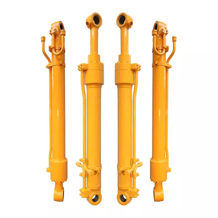
Can hydraulic cylinders be retrofitted onto existing equipment for improved functionality?
Yes, hydraulic cylinders can be retrofitted onto existing equipment to enhance functionality and performance. Retrofitting hydraulic cylinders onto existing machinery or equipment offers several benefits, including increased power, improved control, enhanced precision, and versatility. Here's a detailed explanation of how hydraulic cylinders can be retrofitted onto existing equipment for improved functionality:
1. Increased Power:
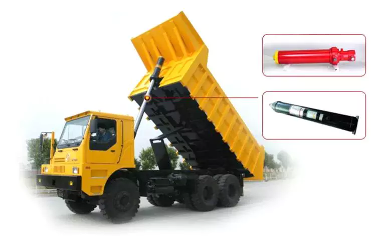
- Retrofitting hydraulic cylinders allows for the addition of hydraulic power to the existing equipment. By integrating hydraulic cylinders, the equipment can generate higher forces and handle heavier loads. This increased power enables the equipment to perform tasks that were previously challenging or impossible. For example, a retrofit hydraulic cylinder on a crane can enhance its lifting capacity and enable it to handle heavier loads more efficiently.
2. Improved Control:
- Hydraulic cylinders provide precise control over the motion and positioning of equipment. By retrofitting hydraulic cylinders, operators gain better control over the speed, force, and direction of movement. The addition of hydraulic control valves and a hydraulic power unit allows for fine-tuning of the equipment's operation. Improved control facilitates safer and more efficient operation, reducing the risk of damage and improving overall productivity.
3. Enhanced Precision:
- Retrofitting hydraulic cylinders onto existing equipment can significantly improve precision and accuracy. Hydraulic systems offer precise control over movement, enabling smooth and controlled motion. This enhanced precision is beneficial in applications where precise positioning or repetitive movements are required. For instance, retrofitting hydraulic cylinders onto a robotic arm can enhance its accuracy and repeatability, making it more suitable for tasks that demand high precision.
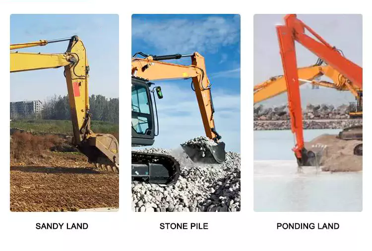
4. Versatility and Adaptability:
- Retrofitting hydraulic cylinders can increase the versatility and adaptability of existing equipment. Hydraulic systems can be easily integrated with various types of machinery, allowing for the utilization of hydraulic power across different applications. The modular nature of hydraulic components facilitates the retrofitting process, enabling the equipment to perform a broader range of tasks. This versatility is particularly advantageous in industries where equipment needs to adapt to changing operational requirements.
5. Retrofit Kits and Customization:
- Manufacturers often provide retrofit kits that include all the necessary components for integrating hydraulic cylinders onto existing equipment. These kits typically consist of hydraulic cylinders, mounting brackets, hoses, fittings, control valves, and other required accessories. Retrofit kits simplify the retrofitting process and ensure compatibility between the hydraulic components and the existing equipment. Additionally, manufacturers can offer customization options to tailor the retrofit solution to specific equipment and application needs.
6. Cost-Effective Solution:
- Retrofitting hydraulic cylinders onto existing equipment can be a cost-effective solution compared to purchasing new machinery. By leveraging the existing equipment's structural framework and mechanical components, the overall cost of upgrading can be reduced. Retrofitting also minimizes downtime since the equipment does not need to be completely replaced. Furthermore, the improved functionality and performance resulting from the retrofit can lead to increased productivity and cost savings in the long run.
7. Professional Installation and Expertise:
- Retrofitting hydraulic cylinders onto existing equipment often requires professional installation and expertise. Working with experienced hydraulic system integrators or manufacturers ensures proper installation, compatibility, and optimal performance of the retrofit solution. These professionals can assess the existing equipment, recommend suitable hydraulic components, and carry out the retrofitting process efficiently. Their knowledge and expertise contribute to the successful integration of hydraulic cylinders and the overall improvement of equipment functionality.
In summary, hydraulic cylinders can indeed be retrofitted onto existing equipment to improve functionality. This retrofitting process offers advantages such as increased power, improved control, enhanced precision, versatility, cost-effectiveness, and access to retrofit kits and customization options. By retrofitting hydraulic cylinders, existing equipment can be upgraded to meet evolving operational needs, extend its lifespan, and enhance overall performance.
Advancements in Hydraulic Cylinder Technology Improving Corrosion Resistance
Advancements in hydraulic cylinder technology have led to significant improvements in corrosion resistance. Corrosion is a major concern in hydraulic systems, especially in environments where cylinders are exposed to moisture, chemicals, or corrosive agents. These advancements aim to enhance the durability and longevity of hydraulic cylinders. Let's explore some of the key advancements in hydraulic cylinder technology that have improved corrosion resistance:
- Corrosion-Resistant Materials: The use of corrosion-resistant materials is a fundamental advancement in hydraulic cylinder technology. Stainless steel, for example, offers excellent resistance to corrosion, making it a popular choice in marine, offshore, and other corrosive environments. Additionally, advancements in metallurgy have led to the development of specialized alloys and coatings that provide enhanced corrosion resistance, extending the lifespan of hydraulic cylinders.
- Surface Treatments and Coatings: Various surface treatments and coatings have been developed to protect hydraulic cylinders from corrosion. These treatments can include electroplating, galvanizing, powder coating, and specialized corrosion-resistant coatings. These coatings create a barrier between the cylinder surface and corrosive elements, preventing direct contact and inhibiting the onset of corrosion. The selection of appropriate coatings depends on the specific application and environmental conditions.
- Sealing Technology: Effective sealing systems are crucial in preventing water, moisture, and contaminants from entering the cylinder and causing corrosion. Advancements in sealing technology have led to the development of high-quality seals and advanced sealing designs that offer superior resistance to corrosion. These seals are typically made from materials specifically engineered to withstand corrosive environments, ensuring long-term sealing performance and minimizing the risk of corrosion-related issues.
- Improved Surface Finishes: The surface finish of hydraulic cylinders plays a role in their resistance to corrosion. Advancements in machining and polishing techniques have allowed for smoother and more uniform surface finishes. Smoother surfaces reduce the likelihood of corrosion initiation and make it easier to clean and maintain hydraulic cylinders. Additionally, specialized finishes, such as passivation or chemical treatments, can be applied to further enhance corrosion resistance.
- Environmental Protection Features: Hydraulic cylinders can be equipped with additional features to protect against corrosion. These features may include protective boots, bellows, or shields that guard vulnerable areas from exposure to corrosive agents. By incorporating these protective elements into the design, hydraulic cylinders can withstand harsh environments and minimize the risk of corrosion-related damage.
In summary, advancements in hydraulic cylinder technology have significantly improved corrosion resistance. The use of corrosion-resistant materials, advanced surface treatments and coatings, innovative sealing technology, improved surface finishes, and the incorporation of environmental protection features have all contributed to enhanced durability and longevity of hydraulic cylinders in corrosive environments. These advancements ensure reliable performance and reduce the maintenance and replacement costs associated with corrosion-related issues.
How do hydraulic cylinders generate force and motion using hydraulic fluid?
Hydraulic cylinders generate force and motion by utilizing the principles of fluid mechanics, specifically Pascal's law, in conjunction with the properties of hydraulic fluid. The process involves the conversion of hydraulic energy into mechanical force and linear motion. Here's a detailed explanation of how hydraulic cylinders achieve this:
1. Pascal's Law:
- Hydraulic cylinders operate based on Pascal's law, which states that when pressure is applied to a fluid in a confined space, it is transmitted equally in all directions. In the context of hydraulic cylinders, this means that when hydraulic fluid is pressurized, the force is evenly distributed throughout the fluid and transmitted to all surfaces in contact with the fluid.
2. Hydraulic Fluid and Pressure:
- Hydraulic systems use a specialized fluid, typically hydraulic oil, as the working medium. This fluid is stored in a reservoir and circulated through the system by a hydraulic pump. The pump pressurizes the fluid, creating hydraulic pressure that can be controlled and directed to various components, including hydraulic cylinders.
3. Cylinder Design and Components:
- Hydraulic cylinders consist of several key components, including a cylindrical barrel, a piston, a piston rod, and various seals. The barrel is a hollow tube that houses the piston and allows for fluid flow. The piston divides the cylinder into two chambers: the rod side and the cap side. The piston rod extends from the piston and provides a connection point for external loads. Seals are used to prevent fluid leakage and maintain hydraulic pressure within the cylinder.
4. Fluid Input and Motion:
- To generate force and motion, hydraulic fluid is directed into one side of the cylinder, creating pressure on the corresponding surface of the piston. This pressure is transmitted through the fluid to the other side of the piston.
5. Force Generation:
- The force generated by a hydraulic cylinder is a result of the pressure applied to a specific surface area of the piston. The force exerted by the hydraulic cylinder can be calculated using the formula: Force = Pressure × Area. The area is determined by the diameter of the piston or the piston rod, depending on which side of the cylinder the fluid is acting upon.
6. Linear Motion:
- As the pressurized hydraulic fluid acts on the piston, it generates a force that moves the piston in a linear direction within the cylinder. This linear motion is transferred to the piston rod, which extends or retracts accordingly. The piston rod can be connected to external components or machinery, allowing the generated force to perform various tasks, such as lifting, pushing, pulling, or controlling mechanisms.
7. Control and Regulation:
- The force and motion generated by hydraulic cylinders can be controlled and regulated by adjusting the flow of hydraulic fluid into the cylinder. By regulating the flow rate, pressure, and direction of the fluid, the speed, force, and direction of the cylinder's movement can be precisely controlled. This control allows for accurate positioning, smooth operation, and synchronization of multiple cylinders in complex machinery.
8. Return and Recirculation of Fluid:
- After the hydraulic cylinder completes its stroke, the hydraulic fluid on the opposite side of the piston needs to be returned to the reservoir. This is typically achieved through hydraulic valves that control the flow direction, allowing the fluid to return and be recirculated in the system for further use.
In summary, hydraulic cylinders generate force and motion by utilizing the principles of Pascal's law. Pressurized hydraulic fluid acts on the piston, creating force that moves the piston in a linear direction. This linear motion is transferred to the piston rod, allowing the generated force to perform various tasks. By controlling the flow of hydraulic fluid, the force and motion of hydraulic cylinders can be precisely regulated, contributing to their versatility and wide range of applications in machinery.


editor by CX 2023-11-03
China manufacturer Roll Forming Machine Worm Reduction Motor Supply Marine Gearbox manufacturer
Product Description
Hot Sales
Product Description
Roll forming machine worm reduction industrial d300 boat comer brushless dc motor supply marine gearbox
| Feature | Oil pump rotating 180 degree can change the input direction | |||
| Housing:SAE 0.1 | Flange::14",16",18" | |||
| L×W×H | N.W. | |||
| 300 | 910×800×1080mm | 700kg | ||
| D300A | 910×855×1225mm | 940kg | ||
| Nominal coefficient | Accurate coefficient |
Ratio (horsepower/r/m)(300) |
Ratio (horsepower/r/m)(J300) |
|
| 300 | 2:01 | 2.04:1 | 0.35 | 0.42 |
| 2.5:1 | 2.54:1 | 0.35 | 0.42 | |
| 3:01 | 3.0:1 | 0.33 | 0.396 | |
| 3.5:1 | 3.53:1 | 0.3 | 0.36 | |
| 4:01 | 4.10:1 | 0.25 | 0.3 | |
| D300A | 4:01 | 4.00:1 | 0.35 | |
| 4.5:1 | 4.48:1 | 0.33 | ||
| 5:01 | 5.05:1 | 0.3 | ||
| 5.5:1 | 5.52:1 | 0.25 | ||
| 6:01 | 5.90:1 | 0.25 | ||
| 6.5:1 | 6.56:1 | 0.2 | ||
| 7:01 | 7.06:1 | 0.2 | ||
| 7.5:1 | 7.63:1 | 0.17 | ||
|
Recommended engine: CUMMINS VTA28-M;CAT 3412TA;GARDNER 6LYT1; DETROIT 12V92TA;BAUDOUIN 12P15.2S DAUHATSU M5S |
||||
Advantage Products
Company Profile
Packaging & Shipping
Contact us
| Product Name: | Small Boat Marine Reverse Gearbox |
|---|---|
| Input Speed: | 750rpm |
| Color: | Blue |
| Output Torque: | 264mm / 355mm |
| Output Speed: | 2500rpm |
| Gearing Arrangement: | Harmonic |
| Customization: |
Available
| Customized Request |
|---|

Calculating Gear Ratio in a Worm Reducer
The gear ratio in a worm reducer is determined by the number of teeth on the worm wheel (also known as the worm gear) and the number of threads on the worm shaft. The gear ratio formula for a worm reducer is:
Gear Ratio = Number of Teeth on Worm Wheel / Number of Threads on Worm Shaft
For example, if the worm wheel has 60 teeth and the worm shaft has a single thread, the gear ratio would be 60:1.
It's important to note that worm reducers have an inherent self-locking property due to the angle of the worm threads. As a result, the gear ratio also affects the mechanical advantage and the system's ability to resist backdriving.
When calculating the gear ratio, ensure that the worm reducer is properly designed and that the gear ratio aligns with the desired mechanical characteristics for your application. Additionally, consider factors such as efficiency, load capacity, and speed limitations when selecting a gear ratio for a worm reducer.

Diagnosing and Fixing Oil Leakage in a Worm Gearbox
Oil leakage in a worm gearbox can lead to reduced lubrication, increased friction, and potential damage to the gearbox components. Here's a step-by-step process to diagnose and fix oil leakage:
- Inspect the Gearbox: Perform a visual inspection of the gearbox to identify the source of the leakage. Check for oil stains, wet spots, or oil pooling around the gearbox.
- Check Seals and Gaskets: Inspect the seals, gaskets, and O-rings for any signs of wear, cracks, or damage. These components are common points of leakage.
- Tighten Bolts and Fasteners: Ensure that all bolts, screws, and fasteners are properly tightened. Loose fasteners can create gaps that allow oil to escape.
- Replace Damaged Seals: If you find damaged seals or gaskets, replace them with new ones. Use seals that are compatible with the operating conditions and lubricant.
- Check Breather Vent: A clogged or malfunctioning breather vent can cause pressure buildup inside the gearbox, leading to leakage. Clean or replace the breather vent if necessary.
- Examine Shaft Seals: Check the shaft seals for wear or damage. If they're worn out, replace them with seals of the appropriate size and material.
- Use Proper Lubricant: Ensure that you're using the correct lubricant recommended for the gearbox. Using the wrong type of lubricant can cause leaks.
- Apply Sealants: In some cases, applying a suitable sealant to the joints and connections can help prevent leaks. Follow the manufacturer's instructions for proper application.
- Monitor Leakage: After addressing the issues, monitor the gearbox for any signs of continued leakage. If leakage persists, further investigation may be required.
- Regular Maintenance: Implement a regular maintenance schedule that includes checking seals, gaskets, and other potential leakage points. Timely maintenance can prevent future leakage issues.
If you're unsure about diagnosing or fixing oil leakage in a worm gearbox, consider consulting with a professional or gearbox manufacturer to ensure proper resolution.

Preventing Backlash in a Worm Gearbox
Backlash in a worm gearbox can lead to reduced accuracy, positioning errors, and decreased overall efficiency. Here are steps to prevent or minimize backlash:
- High-Quality Components: Use high-quality worm gears and worm wheels with tight manufacturing tolerances. Precision components will help reduce backlash.
- Proper Meshing: Ensure the worm gear and worm wheel are properly aligned and meshed. Improper meshing can lead to increased backlash.
- Preload: Applying a small amount of preload to the worm gear can help reduce backlash. However, excessive preload can increase friction and wear.
- Anti-Backlash Mechanisms: Consider using anti-backlash mechanisms, such as spring-loaded systems or adjustable shims, to compensate for any inherent backlash.
- Lubrication: Proper lubrication can reduce friction and play a role in minimizing backlash. Use a lubricant that provides good film strength and reduces wear.
- Maintenance: Regularly inspect and maintain the gearbox to identify and address any changes in backlash over time.
It's important to strike a balance between reducing backlash and maintaining smooth operation. Consulting with gearbox experts and following manufacturer guidelines will help you optimize your worm gearbox's performance while minimizing backlash.


editor by CX 2023-09-18