Product Description
Product Description
CHINAMFG planetary reducer gearbox is designed with large torque, high start and transmission efficiency, low-speed stability,compact radial size, low noise, etc. The main devices we are making are walking reducers, lifting reducers and swing reducers.
They are widely used for vehicle cranes, crawler cranes, truck mounted cranes, marine cranes, aerial work trucks, excavators, etc.
1)Compact size
2)Low noise
3)High transmission efficiency
4)Good working condition under lower speed
5)Customized hydraulic motors
and brakes for different request
6)One Year Warranty from reception 7)Free components for replacement within warranty period
8)Professional and tailored solution for different requirements
9)Free technical support at any time
10)Customer training isavailable.
Product Parameters
|
Slewing Reducer
|
||||
|
Model
|
DH12B20E
|
DH17B32E
|
DH18B39S
|
DH25B32S
|
|
Max. output torque
|
12000 Nm
|
16500 Nm
|
17500 Nm
|
25000 Nm
|
|
Ratio
|
20.9
|
31.36
|
38.82
|
31.36
|
|
Weight (no motor, oil, drum)
|
125 kgs
|
165 kgs
|
225 kgs
|
240 kgs
|
|
Modules of output gear; Modification Coefficient
|
m=8,10,12,14mm; x=0.5
|
m=8,10,12,14mm; x=0.5
|
m=8,10,12,14mm; x=0.5
|
m=12,14,16mm; x=0.5
|
|
Model
|
DH29B40S
|
DH29B60S
|
DH38B100S
|
DH50B120S
|
|
Max. output torque
|
28500 Nm
|
29000 Nm
|
38000 Nm
|
48500 Nm
|
|
Ratio
|
39.43
|
60.13
|
100.75
|
120.83
|
|
Weight (no motor, oil, drum)
|
210-260 kgs
|
250 kgs
|
315 kgs
|
380-425 kgs
|
|
Modules of output gear; Modification Coefficient
|
m=12,14,16mm; x=0.5
|
m=12,14,16mm; x=0.5
|
m=12,14,16mm; x=0.5
|
m=16 or 18mm; x=0.5
|
|
Hydraulic motor
|
Motor interface structure can be designed with customer requirement
|
|||
|
Remark
|
1. The input steering direction is opposite to the output. 2. For more ratio requirements, please consult us.
|
|||
Packaging & Shipping
1. Packed by wooden box, fumigation-free for export and import standard.
2. Shipped by sea or air with customer require
Company Profile
FAQ
/* January 22, 2571 19:08:37 */!function(){function s(e,r){var a,o={};try{e&&e.split(",").forEach(function(e,t){e&&(a=e.match(/(.*?):(.*)$/))&&1
| Application: | Electric Cars, Machinery, Marine, Car, Lift Equipment |
|---|---|
| Hardness: | Hardened Tooth Surface |
| Installation: | Vertical Type |
| Layout: | Coaxial |
| Step: | Four-Step |
| Ratio: | Customized |
| Customization: |
Available
| Customized Request |
|---|

How do manufacturers ensure the precision of gear tooth profiles in gear reducers?
Manufacturers employ several techniques to ensure the precision of gear tooth profiles in gear reducers, which is crucial for optimal performance and efficiency:
1. Precision Machining: Gear teeth are typically machined using advanced CNC (Computer Numerical Control) machines that can achieve high levels of accuracy and repeatability. This ensures consistent gear tooth profiles across multiple components.
2. Quality Control Measures: Rigorous quality control processes, such as dimensional inspections and profile measurements, are performed at various stages of manufacturing to verify that gear tooth profiles meet the required specifications.
3. Tooth Profile Design: Engineers use specialized software and simulation tools to design gear tooth profiles with precise involute shapes and accurate dimensions. These designs are then translated into machine instructions for manufacturing.
4. Material Selection: High-quality materials with excellent wear resistance and dimensional stability are chosen to minimize the potential for deformation or inaccuracies during machining and operation.
5. Heat Treatment: Heat treatment processes, such as carburizing and quenching, are applied to enhance the surface hardness and durability of gear teeth, reducing the risk of wear and deformation over time.
6. Tooth Grinding and Finishing: After initial machining, gear teeth often undergo precision grinding and finishing processes to achieve the desired tooth profile accuracy and surface finish.
7. Post-Processing Inspection: Gear tooth profiles are inspected again after manufacturing processes to verify that the final components meet the specified tolerances and performance criteria.
8. Computer-Aided Manufacturing (CAM): CAM software is used to generate tool paths and machining instructions, enabling precise control over tool movements and material removal during gear manufacturing.
By combining these techniques and leveraging advanced manufacturing technologies, manufacturers can achieve the necessary precision in gear tooth profiles, resulting in reliable and efficient gear reducers for various industrial applications.

What maintenance practices are essential for prolonging the lifespan of gear reducers?
Proper maintenance is crucial for extending the lifespan and ensuring optimal performance of gear reducers. Here are essential maintenance practices:
- 1. Lubrication: Regular lubrication of gear reducers is vital to reduce friction, wear, and heat generation. Use the recommended lubricant and follow the manufacturer's guidelines for lubrication intervals.
- 2. Inspection: Routinely inspect gear reducers for signs of wear, damage, or leaks. Check for unusual noises, vibrations, or temperature increases during operation.
- 3. Alignment: Ensure proper alignment of the input and output shafts. Misalignment can lead to increased wear, noise, and reduced efficiency. Align the components according to the manufacturer's specifications.
- 4. Cooling and Ventilation: Maintain proper cooling and ventilation to prevent overheating. Ensure that cooling fans and vents are clean and unobstructed.
- 5. Seal Maintenance: Inspect and replace seals as needed to prevent contaminants from entering the gear reducer. Contaminants can lead to accelerated wear and reduced performance.
- 6. Bolts and Fasteners: Regularly check and tighten bolts and fasteners to prevent loosening during operation, which can cause misalignment or component damage.
- 7. Replacing Worn Components: Replace worn or damaged components, such as gears, bearings, and seals, with genuine parts from the manufacturer.
- 8. Vibration Analysis: Conduct periodic vibration analysis to identify potential issues early. Excessive vibration can indicate misalignment or component wear.
- 9. Maintenance Records: Keep detailed maintenance records, including lubrication schedules, inspection dates, and component replacements. This helps track the history of the gear reducer and aids in future maintenance planning.
- 10. Training: Provide proper training to maintenance personnel on gear reducer maintenance and troubleshooting techniques.
By adhering to these maintenance practices, you can maximize the lifespan of your gear reducers, minimize downtime, and ensure reliable operation in your industrial processes.

Can you explain the different types of gear reducers available in the market?
There are several types of gear reducers commonly used in industrial applications:
1. Spur Gear Reducers: These reducers have straight teeth and are cost-effective for applications requiring moderate torque and speed reduction. They are efficient but may produce more noise compared to other types.
2. Helical Gear Reducers: Helical gears have angled teeth, which provide smoother and quieter operation compared to spur gears. They offer higher torque capacities and are suitable for heavy-duty applications.
3. Bevel Gear Reducers: Bevel gears have conical shapes and intersect at an angle, allowing them to transmit power between non-parallel shafts. They are commonly used in applications where shafts intersect at 90 degrees.
4. Worm Gear Reducers: Worm gears consist of a worm (screw) and a mating gear (worm wheel). They offer high torque reduction and are used for applications requiring high ratios, although they can be less efficient.
5. Planetary Gear Reducers: These reducers use a system of planetary gears to achieve high torque output in a compact design. They provide excellent torque multiplication and are commonly used in robotics and automation.
6. Cycloidal Gear Reducers: Cycloidal drives use an eccentric cam to achieve speed reduction. They offer high shock load resistance and are suitable for applications with frequent starting and stopping.
7. Harmonic Drive Reducers: Harmonic drives use a flexible spline to achieve high gear reduction ratios. They provide high precision and are commonly used in applications requiring accurate positioning.
8. Hypoid Gear Reducers: Hypoid gears have helical teeth and non-intersecting shafts, making them suitable for applications with space limitations. They offer high torque and efficiency.
Each type of gear reducer has its own advantages and limitations, and the choice depends on factors such as torque requirements, speed ratios, noise levels, space constraints, and application-specific needs.


editor by CX 2024-04-02
China best CZPT Tmg71.2 12 Cub Truck Mixer Planetary Gearbox (with water pump connection) manufacturer
Product Description
Absolute dependability, low maintenance, compactness and cost-effectiveness are the key features of the redesigned CZPT series, the unparalleled line of drives for transit mixers. Ten models available for mixing capacity ranging from 1 to 20 m3.
Features:
Compact structure and space-saving design
Robust main bearing system
High torque capacity
High load capacity
Integrated static multiple disk parking brake
Optional Disconnect device for towing
Optional Quick disconnection device
Simple mounting
Easy oil change
Low-noise running operation
1.Our material warehouse
2. Our machining euqipment
3 Our Inspection equipment
4 Our assembly line
5 Our testing machine
6 Our painting line
7 Finished gearbox warehouse
In conclusion, ELITE Hydraulic offers quality, value, and professional power transmission solutions that cater to a wide variety of industries. With their expertise, experience, and commitment to customer satisfaction, you can be sure that you're in safe hands when working with them. Whether you need travel gearbox, electrical drive, travel drive,slew gearbox,winche gearbox,cutter gearbox,truck mixer gearbox,twin shaft mixer or other hydraulic transmission solutions, you can trust ELITE Hydraulic to provide you with the best possible solutions. Contact them today to learn more about their power transmission products and services.
/* January 22, 2571 19:08:37 */!function(){function s(e,r){var a,o={};try{e&&e.split(",").forEach(function(e,t){e&&(a=e.match(/(.*?):(.*)$/))&&1
| Application: | Motor, Motorcycle, Machinery, Agricultural Machinery |
|---|---|
| Function: | Change Drive Torque, Speed Changing, Speed Reduction |
| Hardness: | Hardened Tooth Surface |
| Step: | Three-Step |
| Type: | Planetary Gear Box |
| Warranty: | 18 Months |
| Customization: |
Available
| Customized Request |
|---|
Choosing the Right Agricultural Gearbox
There are a number of different types of agricultural gearboxes available. Some are Bevel, while others are Shaft-mounted, bearing-mounted, or CZPT gearboxes. To learn more about these different types, read on. We'll explain how each works and what to look for in an agricultural gearbox. Alternatively, you can search for information on each type on the web. Agricultural gearboxes can be a great option for your next project.
Bevel gearboxes
Bevel gearboxes are a type of mechanical transmission system that uses enclosed spiral and straight bevel-gears to transmit rotational power. They are typically mounted on a right-angle shaft and have a wide range of horsepower and ratios. Some bevel gearboxes are designed to be installed at varying angles. For example, CZPT Gearbox provides bevel gear drives for portable grain augers, elevators, and carts.
Bevel gearboxes are the most common type of gearbox. They have a single-stage design and the beveled edges of two gears interlock to transfer torque and rotation. Bevel gearboxes have multiple advantages over other types of gearboxes. They are also more cost-effective, run quietly, and produce less transmittable torque. They are designed to be used in low-torque applications.
A right-angle gearbox is used for a variety of agricultural applications. It is well-suited for use with offset rotary fillers and hollow output shafts. It has a reduction ratio of 2.44:1. The gearbox is built with a cast-iron case and can produce power rates up to 49kW. These bevel gearboxes are used in small agricultural work, including crop treatment, soil preparation, and cement mixers.
Spiral and straight bevel gears have two major benefits. The first is more durable, while the latter is quieter. Both types have their advantages and disadvantages. Bevel gears can be noisy, so they may not be the best choice for your equipment. But the latter has many benefits. The Spiral bevel gear has a high degree of total coverage, but it costs more to produce.
Shaft-mounted
Shaft-mounted agricultural gearboxes are designed for conveyer systems. These devices have interchangeable mounting dimensions with CZPT and CZPT gearboxes. Agricultural gearboxes are critical to the entire food chain. Worn gears can cause significant loss to farmers. As a result, it is essential to purchase high-quality gearboxes for your farm equipment. The following are some tips to choose the right gearbox for your needs.
Agricultural tractors include an internal combustion engine 10 and a speed change gearbox. The engine's cylinder block is mounted on the gearbox casing. The gearbox casing extends under the driver's position and has an elongated shape in the longitudinal direction. The gearbox casing is connected to the rear axle casing 15 by a connecting shaft. The shafts are designed to engage and disengage in opposite directions.
The mounting position of the gearbox is an important consideration. Some applications require no foundation for the gear drive. Generally, a shaft-mounted agricultural gearbox can be attached to the drive equipment via a low-speed shaft. In addition, the shaft is secured around a solid shaft. Rigid flange couplings may be used to connect the gear drive and driven equipment. This type of mounting is preferred for applications where there is no foundation.
Shaft-mounted agricultural gearboxes are designed to optimize machine performance. CZPT Gearbox Company is an innovative company that manufactures top-quality gear drives for a variety of agricultural machinery. They can reverse engineer existing designs or create custom gearboxes for your farm machinery. These agricultural gearboxes are designed to help farmers optimize their machines for maximum efficiency. They transmit power from the input shaft to the output shafts and facilitate change of speed, direction, and rotation.
Shaft-mounted with bearings
If you are looking to buy an agricultural gearbox, it will be beneficial to look at the different types of shaft-mounted gearboxes available. Shaft-mounted gearboxes are often made of steel, and are commonly constructed with AGMA class 12 gearing. They typically utilize tapered roller bearings on all shafts, and have a patented triple seal system that prevents dirt and moisture from getting inside. Additionally, they are easy to install and remove, as they don't require any tools. Finally, they are built to last with minimal maintenance, and will provide maximum uptime.
Shaft-mounted agricultural gearboxes are generally made of steel, and are available in both cylindrical and square shapes. Some types of shafts are able to rotate axially within the bearing while maintaining radial load carrying capabilities. Despite the differences in the shapes of these shafts, they offer high levels of efficiency and performance. For example, the Float-A-Shaft(r) 3 to 2 right-angle gearbox can accommodate both round and square-base mounting, and is capable of generating up to 1100 in-lbs of torque.
Shaft-mounted agricultural gearboxes are constructed from two types of roller bearings: cylindrical roller bearings and tapered roller bearings. A cylindrical roller bearing has one row of balls that are enclosed within a cage, and it has a single axis. The other two rows of bearings have a single or double-row arrangement. Both of them have high axial rigidity and can handle high axial loads.
CZPT gearboxes
The demand for food has skyrocketed since the turn of the century, and the World Bank estimates that the number of people on the planet will grow by 80 million annually by 2025. As the demand for food grows, agricultural machinery manufacturers are coming up with innovative ways to make the most of their land. This results in shorter cropping cycles and greater wear and tear on farm equipment, including CZPT agricultural gearboxes.
Bevel gearboxes are enclosed straight or spiral gears that transmit rotational power to various parts of agricultural machinery. They are available in a variety of right-angle and spiral configurations. The CZPT Gearbox, for example, features a 68-degree bevel gear drive for augers and grain carts. The company also offers a 50-degree bevel gear drive. These gearboxes are made with the latest technology and incorporate horizontally split housing designs.
Agricultural gearboxes from CZPT are available in a variety of designs, including reversing gears. Reversing gears feature ball bearings that reduce friction and increase efficiency. This gearbox can be purchased in a wide range of power ratings and blade counts, allowing the farmer to choose the one that works best for their needs. This will ensure long-term functionality and effectiveness. So whether you're a farmer or a manufacturer of agricultural equipment, a CZPT agricultural gearbox will work for you.
Bevel gearboxes with bearings
The bevel gearing is a popular choice for agricultural gearboxes due to its high load capacity. The bevel gearing is widely used in mechanical transmission systems, including agricultural tractors. For modern harvesters, high-performance gearboxes are necessary for smooth operation. Leading agricultural equipment manufacturers rely on CZPT Gearbox Company to provide these high-quality and durable drive systems. This is why we supply bevel gearboxes for agricultural machinery.
A bevel gearbox can be either straight or helical. The latter option is the simplest type and tends to be cheaper to produce. However, it is difficult to realize small profile coverage with straight gearwheels. Furthermore, it is less efficient in transmitting torque. The bevel gearbox can be used for both clockwise and counterclockwise rotation. It is available with a standard mount and aluminum casing.
Depending on the type of agriculture machinery, bevel gearboxes with bearings are suitable for many tasks. Their versatility allows them to be used in a variety of mechanical applications. The double gear allows the upper bevel gear angular gear 2 to pivot relative to the lower bevel gear angular gear 3.
Besides bearings, other factors influence the performance of agricultural gearboxes. Insufficient data may make it difficult to obtain the exact gear. For this reason, a broken gear requires a detailed manufacturing drawing. This drawing requires expertise in technical gear, as well as specialized engineering manpower. It also increases the cost of production. The gears are subjected to heat treatment before being shipped to the customer.
Bevel gearboxes with CZPT gearboxes
The demand for agricultural products has increased dramatically since 2010. The world population is increasing at a rapid pace (80 million people per year until 2025), but land is not. Farmers are looking for ways to maximize their land's potential to grow more food. This increased demand for agricultural machinery is driving the need for highly efficient gearboxes. With replacement parts easily available, manufacturers can meet the growing demand for agricultural equipment.
editor by CX 2024-04-02
China Professional AC Gear Motor Reducer with Worm Gear 76mm DC 24V for Tour Car gearbox drive shaft
Product Description
Product Description
Product Description:
High Power 63mm DC Worm Gear Motor
Upgrade to the High Power version of the 63mm DC worm gear motor from HangZhou Xihu (West Lake) Dis. Motor Co., Ltd. for optimal performance in high-power applications.
Key Features:
- Designed with a 50A stall current for maximum power
- Available with a 48CPR encoder for precise control
- Option to include a back shaft for added versatility
- Choose between a metal brush or carbon brush for customized performance
For reliable power and precision, the 63mm DC worm gear motor is the perfect choice for your project. Upgrade to the High Power version today!
63mm,76mm turboworm gear box motor, low noise and small load torque selection of plastic gear of POM material, there is no requirement for noise, but the choice of metal gear with large load torque. The motor is used in rolling gates, automatic fence doors, glass doors, wipers, wheelchairs, various lifting equipment, kitchen supplies, and other products.
The encoder can be used as a low-cost servo motor and has the same function. Equipped with left and right gearboxes can be used symmetrically, using rolling shafts and oil-bearing to meet various scenarios. Various parameters can be adjusted according to customer requirements, the maximum torque of 12V/24V is 50N.m, for the speed of 10RPM.
| voltage VDC |
no load speed RPM |
no load current A |
load torque KG.CM |
on load speed RPM |
power W |
ratio |
| 12 | 80 | 1.8 | 60 | 68 | 80 | 60:1 |
| 12 | 130 | 1.2 | 33 | 110 | 30 | 20:1 |
| 12 | 150 | 1.2 | 45 | 130 | 30 | 20:1 |
| 12 | 170 | 1.4 | 35 | 150 | 45 | 24:1 |
| 24 | 30 | 1.4 | 60 | 25 | 30 | 60:1 |
| 24 | 65 | 120 | 50 | 60 | 80 | 20:1 |
| 24 | 210 | 1.0 | 40 | 180 | 45 | 75:1 |
Detailed Photos
Product Parameters
Certifications
Packaging & Shipping
Installation Instructions
Company Profile
FAQ
/* January 22, 2571 19:08:37 */!function(){function s(e,r){var a,o={};try{e&&e.split(",").forEach(function(e,t){e&&(a=e.match(/(.*?):(.*)$/))&&1
| Application: | DC Worm Gear Motor |
|---|---|
| Operating Speed: | Low Speed |
| Excitation Mode: | Excited |
| Function: | Driving |
| Casing Protection: | Open Type |
| Number of Poles: | 2 |
| Customization: |
Available
| Customized Request |
|---|

What are the considerations for choosing the appropriate lubrication for gear reducers?
Choosing the appropriate lubrication for gear reducers is crucial for ensuring optimal performance, longevity, and efficiency. Several considerations should be taken into account when selecting the right lubrication:
1. Load and Torque: The magnitude of the load and torque transmitted by the gear reducer affects the lubrication's viscosity and film strength requirements. Heavier loads may necessitate higher viscosity lubricants.
2. Operating Speed: The speed at which the gear reducer operates impacts the lubrication's ability to maintain a consistent and protective film between gear surfaces.
3. Temperature Range: Consider the temperature range of the operating environment. Lubricants with suitable viscosity indexes are crucial to maintaining performance under varying temperature conditions.
4. Contaminant Exposure: If the gear reducer is exposed to dust, dirt, water, or other contaminants, the lubrication should have proper sealing properties and resistance to contamination.
5. Lubrication Interval: Determine the desired maintenance interval. Some lubricants require more frequent replacement, while others offer extended operational periods.
6. Compatibility with Materials: Ensure that the chosen lubricant is compatible with the materials used in the gear reducer, including gears, bearings, and seals.
7. Noise and Vibration: Some lubricants have properties that can help reduce noise and dampen vibrations, improving the overall user experience.
8. Environmental Impact: Consider environmental regulations and sustainability goals when selecting lubricants.
9. Manufacturer Recommendations: Follow the manufacturer's recommendations and guidelines for lubrication type, viscosity grade, and maintenance intervals.
10. Monitoring and Analysis: Implement a lubrication monitoring and analysis program to assess lubricant condition and performance over time.
By carefully evaluating these considerations and consulting with lubrication experts, industries can choose the most suitable lubrication for their gear reducers, ensuring reliable and efficient operation.

Can gear reducers be used for both speed reduction and speed increase?
Yes, gear reducers can be utilized for both speed reduction and speed increase, depending on their design and arrangement. The functionality to either decrease or increase rotational speed is achieved by altering the arrangement of gears within the gearbox.
1. Speed Reduction: In speed reduction applications, a gear reducer is designed with gears of different sizes. The input shaft connects to a larger gear, while the output shaft is connected to a smaller gear. As the input shaft rotates, the larger gear turns the smaller gear, resulting in a decrease in output speed compared to the input speed. This configuration provides higher torque output at a lower speed, making it suitable for applications that require increased force or torque.
2. Speed Increase: For speed increase, the gear arrangement is reversed. The input shaft connects to a smaller gear, while the output shaft is connected to a larger gear. As the input shaft rotates, the smaller gear drives the larger gear, resulting in an increase in output speed compared to the input speed. However, the torque output is lower than that of speed reduction configurations.
By choosing the appropriate gear ratios and arrangement, gear reducers can be customized to meet specific speed and torque requirements for various industrial applications. It's important to select the right type of gear reducer and configure it correctly to achieve the desired speed reduction or speed increase.

How do gear reducers contribute to speed reduction and torque increase?
Gear reducers play a crucial role in mechanical systems by achieving speed reduction and torque increase through the principle of gear ratios. Here's how they work:
Gear reducers consist of multiple gears with different sizes, known as gear pairs. These gears are meshed together, and their teeth interlock to transmit motion and power. The gear ratio is determined by the ratio of the number of teeth on the input gear (driver) to the number of teeth on the output gear (driven).
Speed Reduction: When a larger gear (output gear) is driven by a smaller gear (input gear), the output gear rotates at a slower speed than the input gear. This reduction in speed is proportional to the gear ratio. As a result, gear reducers are used to slow down the rotational speed of the output shaft compared to the input shaft.
Torque Increase: The interlocking teeth of gears create a mechanical advantage that allows gear reducers to increase torque output. When the input gear applies a force (torque) to the teeth, it is transmitted to the output gear with greater force due to the leverage provided by the larger diameter of the output gear. The torque increase is inversely proportional to the gear ratio and is essential for applications requiring high torque at lower speeds.
By selecting appropriate gear ratios and arranging gear pairs, gear reducers can achieve various speed reduction and torque multiplication factors, making them essential components in machinery and equipment where precise control of speed and torque is necessary.
editor by CX 2024-04-02
China Custom Desboer ND Series 047MMA Double High Precision Zero Backlashes Round Mounting Planetary Gearbox for 400W-Ish Servo Motor gearbox adjustment
Product Description
Product Description
The ND047A series planetary gearboxes are designed and machined as a single unit with special tapered roller bearings to provide high radial load, high torque, ultra-precision, and small size. The ND series uses in highly rigid industries such as fiber optic laser equipment, floor track equipment, robot seventh axis, Parallel robots (spider hand) machine tools, and rotating arms.
Product Name: High Precision Planetary Reducer
Product Series: ND047A Series
Product features: high torque, high load, ultra-precision, small size
Product Description:
Integrated design concept with high-strength bearings ensure the product itself is durable and efficient
A variety of output ideas such as shaft output, flange and gear are available.
1 arc minute ≤ backlash ≤ 3 arc minutes
Reduction ratios ranging from 3 to 100
Frame design: increases torque and optimizes power transmission
Optimised selection of oil seals: reduces friction and laminate transmission efficiency
Protection class IP65
Warranty: 2 years
Our Advantages
High torque
High load
ultra-precision
Small size
Detailed Photos
Product Parameters
| Segment number | Double segment | ||||||||
| Ratio | i | 16 | 20 | 25 | 35 | 40 | 50 | 70 | 100 |
| Rated output torque | Nm | 18 | 18 | 20 | 18 | 18 | 20 | 18 | 13 |
| Emergency stop torque | Nm | Three times of Maximum Output Torque | |||||||
| Rated input speed | Rpm | 5000 | |||||||
| Max input speed | Rpm | 10000 | |||||||
| Ultraprecise backlash | arcmin | / | |||||||
| Precision backlash | arcmin | ≤5 | |||||||
| Standard backlash | arcmin | ≤7 | |||||||
| Torsional rigidity | Nm/arcmin | 7 | |||||||
| Max.bending moment | Nm | 42.5 | |||||||
| Max.axial force | N | 990 | |||||||
| Service life | hr | 20000(10000 under continuous operation) | |||||||
| Efficiency | % | ≥97% | |||||||
| Weight | kg | 1 | |||||||
| Operating Temperature | ºC | -10ºC~+90ºC | |||||||
| Lubrication | Synthetic grease | ||||||||
| Protection class | IP64 | ||||||||
| Mounting Position | All directions | ||||||||
| Noise level(N1=3000rpm,non-loaded) | dB(A) | ≤56 | |||||||
| Rotary inertia | Kg·cm² | 0.03 | |||||||
Applicable Industries
Packaging Machinery Mechanical Hand Textile Machinery
Non Standard automation Machine Tool Printing Equipment /* January 22, 2571 19:08:37 */!function(){function s(e,r){var a,o={};try{e&&e.split(",").forEach(function(e,t){e&&(a=e.match(/(.*?):(.*)$/))&&1
| Application: | Motor, Machinery, Marine, Agricultural Machinery, CNC Machine |
|---|---|
| Function: | Change Drive Torque, Speed Changing, Speed Reduction |
| Layout: | Plantery Type |
| Hardness: | Hardened Tooth Surface |
| Installation: | All Directions |
| Step: | Double-Step |
| Customization: |
Available
| Customized Request |
|---|

The Role of Harmonic Drive Servo Gearboxes in Advanced Motion Control Systems
Harmonic Drive servo gearboxes play a crucial role in advanced motion control systems by offering several unique features:
1. High Precision: Harmonic Drive gearboxes are known for their exceptional precision due to the unique gear mechanism they employ. This precision is essential for achieving accurate and repeatable motion control.
2. Zero Backlash: Harmonic Drive gearboxes are designed with zero backlash, which means there is no lost motion between input and output. This feature ensures that the commanded motion is precisely transferred without any delays or inaccuracies.
3. Compact Design: Harmonic Drive gearboxes have a compact structure, making them suitable for applications with limited space. The compact design allows for easy integration into various systems.
4. High Torque Transmission: Despite their compact size, harmonic drive gearboxes can transmit high torque efficiently. This feature is essential for applications that require both high precision and high torque.
5. Smooth Motion: The unique wave generator mechanism in harmonic drive gearboxes contributes to smooth and continuous motion, which is particularly beneficial in applications involving robotic arms, satellite positioning, and more.
6. Reduction Ratios: Harmonic Drive gearboxes offer high reduction ratios in a single-stage, allowing for precise control of output motion even when input motion is at high speeds.
7. Low Maintenance: The absence of backlash and the use of high-quality materials result in reduced wear and maintenance requirements, enhancing the longevity of the gearbox.
8. Advanced Applications: Harmonic Drive gearboxes are commonly used in robotics, aerospace, medical equipment, automation, and other industries where precision and reliability are paramount.
Overall, harmonic drive servo gearboxes are a critical component in achieving advanced motion control, enabling engineers to design and operate complex systems with unparalleled precision and accuracy.

Considerations for Selecting the Right Servo Gearbox for an Application
Choosing the appropriate servo gearbox for a specific application requires careful evaluation of several key factors:
1. Torque and Speed Requirements: Determine the required torque and speed characteristics of the application, ensuring that the chosen servo gearbox can provide the necessary output.
2. Gear Ratio: Calculate the ideal gear ratio based on the desired motion profile, acceleration, and deceleration requirements.
3. Mounting and Integration: Consider the available space and mechanical layout of the machinery to choose a servo gearbox with the appropriate mounting configuration.
4. Motor Compatibility: Ensure that the servo gearbox is compatible with the specific type and size of motor being used for the application.
5. Precision and Accuracy: Evaluate the level of precision required for the application's motion control. Choose a servo gearbox that can deliver the necessary accuracy and repeatability.
6. Load Distribution: Analyze how the load will be distributed among the gears to prevent excessive wear and ensure optimal performance.
7. Backlash and Compliance: Consider the application's tolerance for backlash and compliance. Choose a servo gearbox with low backlash if precise positioning is essential.
8. Environmental Conditions: Factor in the environmental conditions of the application, such as temperature, humidity, and exposure to contaminants. Choose a servo gearbox with suitable sealing and protection.
9. Lubrication: Determine the lubrication requirements of the gearbox and select a model that aligns with the application's maintenance practices.
10. Overload and Shock: Consider potential overload and shock conditions the gearbox may experience. Choose a servo gearbox that can handle sudden changes in load without compromising performance.
11. Feedback Devices: If precise motion control is required, choose a servo gearbox that is compatible with the desired feedback devices, such as encoders or resolvers.
12. Efficiency: Evaluate the efficiency of the servo gearbox to ensure that it contributes to the overall energy efficiency of the system.
13. Service and Support: Select a reputable manufacturer that offers reliable technical support, documentation, and post-purchase services.
14. Budget: Balance the performance requirements of the application with the available budget to make an informed decision.
By carefully considering these factors, engineers and designers can confidently choose the right servo gearbox that meets the specific needs of their application, optimizing performance and productivity.

Benefits of Using a Servo Gearbox for Precise Motion Control
Servo gearboxes offer several advantages when it comes to achieving precise motion control in various applications:
1. Accuracy: Servo gearboxes provide exceptional accuracy in speed and position control, making them suitable for applications that require tight tolerances and precise movements.
2. Low Backlash: These gearboxes are designed to minimize backlash, which is essential for eliminating lost motion and ensuring accurate positioning.
3. High Torque Density: Servo gearboxes offer a high torque-to-size ratio, allowing them to handle significant loads while maintaining a compact footprint.
4. Dynamic Performance: They excel in dynamic performance, enabling rapid changes in speed and direction with minimal overshoot or settling time.
5. Responsiveness: Servo gearboxes respond quickly to control signals, making them ideal for applications that require rapid adjustments and changes in direction.
6. Smooth Operation: These gearboxes provide smooth and precise movement, critical for applications like robotics, where jerky or uneven motion can lead to inaccuracies or damage.
7. Reduces Maintenance: The accuracy and durability of servo gearboxes can reduce wear and tear on other components, leading to lower maintenance requirements.
8. Improved Efficiency: Servo gearboxes offer high efficiency in power transmission, contributing to energy savings and minimizing heat generation.
9. Customization: They can be tailored to specific application needs, including factors like reduction ratios, mounting options, and feedback compatibility.
10. Versatility: Servo gearboxes find application in various industries, including robotics, CNC machining, medical equipment, and automation.
Overall, the benefits of using a servo gearbox for precise motion control make them an essential component in applications that demand accuracy, responsiveness, and reliable performance.
editor by CX 2024-04-02
China wholesaler China OEM Manufacturer of High Torque Planetary Speed Reducers/Gear Motors/Helical Reducers for Trucks/Agriculture Parts gearbox definition
Product Description
Company Profile
We CHINAMFG is a OEM factory, accpet customerized. Most of our products are customerzation.The product include gear housing/boxes/reducers, Iron casting products, Aluminum products. Such as auto parts, agriculture parts, and other industrial parts.
We have the most advanced testing facilities, such as spectral analyzer for rubber material chemical composition test, tensile strength testing machine, impact value tester and hardness meter, magnetic particle testing machine, sandblasting machine and heat treatment equipment. Besides, there are numerous advanced equipment in the precision machining workshop: have 23 sets CNC lathes, 10sets vertical CNC boring and milling center and 1 horizontal boring and milling center imported from Korea, 2 general milling machine, and 2 general lathes, 1 grinder, 10sets drilling and tap machines, 2 half automatic saw, and 1 Coordinate Measuring Machine (CMM), 1 Projector and 1 machining surface quality testing machine and 1 Mahr altitude instrument. Our product's tolerance can be controlled under 0.01mm. The testing machine's accuracy is within 0.005mm. ISO9000 has been executed.
Product Specification
| Material Available: | Cast Iron G220, Steel,Alloy,Brass,Etc. | Drawing Format: | PDF, STP, X_T, STEP, DWG, CAD, DXF, IGS etc |
| Tolerance: | (±5um) As customer required | Testing Equipments: | Measurement instrument, projector, CMM, Altimeter, Micrometer, Thread Gages, Calipers, Pin guage etc. |
| Processing: | CNC Milling/Turning/Drilling/Auto Lathe/Etc. | Application: | Machinery/Industrial/Construction/Enegy/Cars/Etc. |
| Samples: | 10-20 days | MOQ: | 200 pcs(according to the diferent products) |
| QC System: | 100% Manual Inspection before shipment | Services: | OEM/ODM/Design |
| Lead time: | Usually in 30-40 days | Package: | Usually in Polywood cases/Customized |
| Payment: | T/T 30% in advanced, balance before shipment | Certifications: | ISO9001:2015 |
| Sea Port: | HangZhou/ZheJiang | Waranty: | 1 year |
Detailed Photos
Our Advantages
1. 20 years of experience in manufacturing and exporting
2. OEM and custom-made service
3. All kinds of castings can be manufactured according to the drawings, samples or specific industry standard
4. Strong engineering team makes high quatliy
5. The coordinated service(casting, machining and surface treatment) make lower price if possible
6. Advanced-level equipments
7. Full material testing process and quatliy control system
8. Quality assurance and delivery on time
Cooperation Partner
Factory Showing
/* January 22, 2571 19:08:37 */!function(){function s(e,r){var a,o={};try{e&&e.split(",").forEach(function(e,t){e&&(a=e.match(/(.*?):(.*)$/))&&1
| Application: | Motor, Electric Cars, Motorcycle, Machinery, Marine, Agricultural Machinery, Car |
|---|---|
| Hardness: | Hardened Tooth Surface |
| Installation: | Horizontal Type |
| Samples: |
US$ 1000/Piece
1 Piece(Min.Order) | Order Sample |
|---|
| Customization: |
Available
| Customized Request |
|---|
.shipping-cost-tm .tm-status-off{background: none;padding:0;color: #1470cc}
|
Shipping Cost:
Estimated freight per unit. |
about shipping cost and estimated delivery time. |
|---|
| Payment Method: |
|
|---|---|
|
Initial Payment Full Payment |
| Currency: | US$ |
|---|
| Return&refunds: | You can apply for a refund up to 30 days after receipt of the products. |
|---|

How do gear reducers enhance the efficiency of conveyor systems and robotics?
Gear reducers play a significant role in improving the efficiency of both conveyor systems and robotics by optimizing speed, torque, and control. Here's how they contribute:
Conveyor Systems:
In conveyor systems, gear reducers enhance efficiency in the following ways:
- Speed Control: Gear reducers allow precise control over the rotational speed of conveyor belts, ensuring that materials are transported at the desired speed for efficient production processes.
- Torque Adjustment: By adjusting gear ratios, gear reducers provide the necessary torque to handle varying loads and prevent overloading, minimizing energy wastage.
- Reverse Operation: Gear reducers enable smooth bidirectional movement of conveyor belts, facilitating tasks such as loading, unloading, and distribution without the need for additional components.
- Synchronization: Gear reducers ensure synchronized movement of multiple conveyor belts in complex systems, optimizing material flow and minimizing jams or bottlenecks.
Robotics:
In robotics, gear reducers enhance efficiency through the following means:
- Precision Movement: Gear reducers provide precise control over the movement of robot joints and arms, enabling accurate positioning and manipulation of objects.
- Reduced Inertia: Gear reducers help reduce the inertia experienced by robotic components, allowing for quicker and more responsive movements while conserving energy.
- Compact Design: Gear reducers offer a compact and lightweight solution for achieving various motion profiles in robotic systems, allowing for efficient use of space and resources.
- Torque Amplification: By amplifying torque from the motor, gear reducers enable robots to handle heavier loads and perform tasks that require greater force, enhancing their overall capabilities.
By providing precise speed control, torque adjustment, and reliable motion transmission, gear reducers optimize the performance of conveyor systems and robotics, leading to improved efficiency, reduced energy consumption, and enhanced operational capabilities.

What role do gear ratios play in optimizing the performance of gear reducers?
Gear ratios play a crucial role in optimizing the performance of gear reducers by determining the relationship between input and output speeds and torques. A gear ratio is the ratio of the number of teeth between two meshing gears, and it directly influences the mechanical advantage and efficiency of the gear reducer.
1. Speed and Torque Conversion: Gear ratios allow gear reducers to convert rotational speed and torque according to the needs of a specific application. By selecting appropriate gear ratios, gear reducers can either reduce speed while increasing torque (speed reduction) or increase speed while decreasing torque (speed increase).
2. Mechanical Advantage: Gear reducers leverage gear ratios to provide mechanical advantage. In speed reduction configurations, a higher gear ratio results in a greater mechanical advantage, allowing the output shaft to deliver higher torque at a lower speed. This is beneficial for applications requiring increased force or torque, such as heavy machinery or conveyor systems.
3. Efficiency: Optimal gear ratios contribute to higher efficiency in gear reducers. By distributing the load across multiple gear teeth, gear reducers with suitable gear ratios minimize stress and wear on individual gear teeth, leading to improved overall efficiency and prolonged lifespan.
4. Speed Matching: Gear ratios enable gear reducers to match the rotational speeds of input and output shafts. This is crucial in applications where precise speed synchronization is required, such as in conveyors, robotics, and manufacturing processes.
When selecting gear ratios for a gear reducer, it's important to consider the specific requirements of the application, including desired speed, torque, efficiency, and mechanical advantage. Properly chosen gear ratios enhance the overall performance and reliability of gear reducers in a wide range of industrial and mechanical systems.
What are the benefits of using a gear reducer in industrial applications?
Gear reducers offer several benefits that make them indispensable in various industrial applications:
1. Speed Reduction: Gear reducers allow the reduction of high-speed input from motors or engines to lower, more usable output speeds for specific applications, ensuring proper equipment operation and safety.
2. Torque Increase: By leveraging the mechanical advantage of gear ratios, gear reducers can significantly increase torque output, enabling the handling of heavy loads and providing the necessary power for tasks such as lifting, conveying, and processing.
3. Precise Control: Gear reducers enable fine-tuning of rotational speed and torque, providing precise control over machinery and processes, which is crucial in industries like manufacturing, material handling, and robotics.
4. Shock Load Absorption: Gear reducers can absorb and dampen sudden shocks or changes in load, protecting both the machinery and connected components from abrupt forces that could otherwise lead to damage.
5. Versatility: With various gear types (e.g., spur, helical, worm) and designs, gear reducers can be tailored to different applications, including those requiring specific speed ratios, torque ranges, and environmental conditions.
6. Efficient Power Transmission: Gear reducers offer high mechanical efficiency, minimizing energy loss during power transmission, which is especially valuable in energy-conscious industries.
7. Compact Design: Gear reducers provide a compact solution for transmitting power and adjusting speeds, making them suitable for installations with space constraints.
8. Reliability and Longevity: Well-designed and properly maintained gear reducers can offer extended service life, contributing to reduced downtime and maintenance costs.
Overall, gear reducers enhance the performance, efficiency, and reliability of industrial equipment, making them essential components in a wide range of applications across various industries.
editor by CX 2024-03-29
China Custom Nmrv110 Worm Gearbox Manufacturer Ratio50 agricultural gearbox near me
Product Description
Overview
-----------------------------------------------------------------------------------------------------------------------------------------------------------------------------------------------------------------------------------------------
Quick Details
Gearing Arrangement: Worm Brand Name: CZPT
Input Speed: 1400 rpm Output Speed: 14 rpm to 186 rpm
Rated Power: 0.06 ~ 4KW Output Torque: 2.6-479N.M
Color: Blue/Silver or on request Origin: ZHangZhoug, China (Mainland)
Warranty: 1 Year Application: Industry
-----------------------------------------------------------------------------------------------------------------------------------------------------------------------------------------------------------------------------------------------
Supply Ability
Supply Ability: 20000 Piece/Pieces per Month
Extra Service: OEM is welcome
QC System: ISO9001:2008
-----------------------------------------------------------------------------------------------------------------------------------------------------------------------------------------------------------------------------------------------
Packaging & Delivery
Package: Wooden box/Paper carton
Port: HangZhou/ZheJiang or on request
-----------------------------------------------------------------------------------------------------------------------------------------------------------------------------------------------------------------------------------------------
| TYPE | Worm Gear Speed Reducer/Worm Gearbox |
| MODEL | NMRV series size:571,030,040,050,063,075,090,110,130,150 |
| RATIO | 5,7.5,10,15,20,25,30,40,50,60,80,100 |
| COLOR | Blue(RAL5571)/Silver grey (RAL9571) or on your request |
| MATERIAL | Housing:Aluminum alloy |
| PACKING | Wooden box/Paper carton |
| BEARING | C&U |
| SEAL | SKF |
| WARRANTY | 1 Year |
| INPUT POWER | 0.09KM-15KM |
| USAGES | Foodstuffs, Ceramics, Packing, Chemicals, Pharmacy, Plastics, Paper-making, Machine-tools |
| IEC FLANGE | IEC standard flange or on request |
| LUBRICANT | Shell or Henry |
About CZPT since 1984
HangZhou Melchizedek Import & Export Co., Ltd. is a leader manufactur in mechanism field and punching/stamp ing field since 1984. Our main product, NMRV worm gear speed reducer and series helical gearbox, XDR, XDF, XDK, XDS have reached the advanced technique index of the congeneric European and Janpanese produc ts. We offer standard gears, sprockets, chains, pulleys, couplings, bushes and so on. We also can accept orders of non-standard products, such as gears, shafts, punching parts ect, according to customers' drawings or sam ples.
Our company has complete set of equipment including CNC, lathes, milling machines, gear hobbing machine, g ear grinding machine, gear honing machine, gear shaping machine, worm grinder, grinding machines, drilling m achines, boringmachines, planer, drawing benches, punches, hydraulic presses, plate shearing machines and s o on. We have advanced testing equipments as well.
Our company has established favorable cooperation relationships with sub-suppliers involving casting, raw material, heat treatment, surface finishing and so on.
The most advantage of the speed reducer is the technique of cobber clad, which can enhance the occlusal force between the bronze and core wheel.
/* January 22, 2571 19:08:37 */!function(){function s(e,r){var a,o={};try{e&&e.split(",").forEach(function(e,t){e&&(a=e.match(/(.*?):(.*)$/))&&1
| Application: | Motor, Machinery, Marine, Agricultural Machinery |
|---|---|
| Hardness: | Hardened Tooth Surface |
| Step: | Single-Step |
| Type: | Worm Reducer |
| Transport Package: | Shrink Packing, Carton Packing |
| Trademark: | OEM; EED |
| Customization: |
Available
| Customized Request |
|---|
Choosing the Right Agricultural Gearbox
When buying an agricultural gearbox, there are a few things to consider. The quality of materials, functionality, and mechanism are crucial factors to durability. A durable device will ensure that you won't have to keep replacing it. Here are some tips to help you select the right one. Let's begin. Read on to learn more about the different features available in agricultural gearboxes. Listed below are a few of the most important factors to consider.
Bevel gearboxes
Agricultural gearboxes are essential to the entire food cycle. If your gears are not in good shape, you will be unable to meet the demand and you will suffer from heightened downtime. Fortunately, there are numerous quality bevel gearboxes available on the market today. In fact, the CZPT Gearbox Company supplies bevel gearboxes for agricultural applications. Here are some of the reasons you should choose the right one.
A bevel gearbox is a single-stage unit that interlocks bevelled edges on two gears to transfer torque and rotation. These gears can be either straight or helical. This type of gearbox is inexpensive to produce and operates quietly. It also has lower transmittable torque. Bevel gearboxes are often used as a low-cost alternative to hypoid gearboxes.
Agricultural bevel gearboxes are used in various applications, including hay balers, combine harvesters, seeders, and plows. These gears are well-suited for use with offset rotary fillers. They offer reduction ratios of up to 2.44 and cast iron cases. They are commonly known as "right-angle gearboxes" or "Parallel SHAFT gearboxes."
Agricultural bevel gearboxes come in many sizes and ratios. In general, higher sizes are made of closed-grain cast-iron. Other materials, such as SG 500/7, are used for larger sizes. The main gear and each drive gear are mesh-mounted, and the shafts are designed to rotate in either direction. They have oil seals on the joints. The Spiral Bevel Gearbox is best suited for FG60 or FG75 motors.
The RINV-OP65 right-angle angular gearbox comes with an optional electronic or mechanical position indicator. Its angular design allows for changes in axis rotation, and provides smooth power transmission with minimal backlash. Premium gearmotors include hardened spiral bevel gears and stainless steel shafts for quiet operation. They are available in various ratios and shaft styles. If you want to choose one, make sure it is made to fit the needs of the machine.
Closed-loop seals
There are a number of reasons to install closed-loop seals in an agricultural gearbox. The first is the need to isolate the gearbox from the atmosphere, an important safety concern. Closed-loop seals are CZPT alternatives to desiccant breathers because they prevent the entry of water. While these seals can't keep the gearbox underwater, they isolate the gearbox from the atmosphere and are therefore vital for the safety of your equipment.
The most common material used for these seals is polymer rubber. Most are made from HBR, which stands for High-cis polybutadiene rubber. Other materials include Butadiene and FKM, which are known for their high-temperature performance. However, the disadvantage of these seals is that they are susceptible to shaft damage and degrade quickly in high temperatures. Therefore, you should always consider the type of seal before purchasing one.
If you plan to use agricultural gearboxes on a regular basis, you should consider getting a good quality one. You should look for a closed-loop seal on your gearbox to protect it against dirt and debris. A quality agricultural gearbox also has an easy-access design, which will make it easy to access and maintain. This will ensure its long-lasting performance and low-maintenance costs.
Agricultural equipment is frequently used to perform various tasks, such as sowing seeds, spreading fertilizer, digging holes, and more. This requires durable and effective sealing solutions to keep dirt out of the system and lubricants in. A close-loop seal helps to ensure that all these operations are performed at maximum efficiency. If you're a farmer, closed-loop seals are the ideal solution for you.
Surface finish
The surface finish of an agricultural gearbox should be free from defects in the casting process and mechanical damage. The bearing hole in the shaft must be a minimum of 100 mm long and the distance between the bearing holes should be equal to the shaft length. The shaft should be free of any cracks or burrs. The ellipticity and centerline irregularity of the shaft must be less than 0.015 mm. Likewise, the diameter of the shaft, hole spacing and bearing hole relationship should be at least 20 mm.
In recent studies, researchers have investigated the efficiency of different surfaces on the same materials. They found that surface roughness affects gearbox efficiency. Kahraman et al. reported that superfinishing the gears and reducing surface roughness improved efficiency. In addition, Andersson et al. investigated the impact of different assembly processes on the gearbox' surface roughness. The results of their studies are presented in Table I.
The quality of the surface finish of an agricultural gearbox depends on the materials used. A typical example is wrought steel gear. The die inserts for a forged gear were made of H11 or H13 tool steel. This material softens over time and has a limited life span. An improved alternative was Alloy 718. This alloy has a high temperature range and is suitable for high rotational speeds.
A good surface finish is vital for the health and safety of an agricultural gearbox. It protects the entire food chain and is necessary for agricultural production. The heightened demand for food will cause increased wear and tear on farm machinery. Moreover, a damaged gear will cost the farmer a lot of money. Therefore, it is crucial for farmers to invest in a high-quality agricultural gearbox to avoid such costly downtimes.
Shaft arrangement
An agricultural gearbox has two main stages, the first of which is the reduction stage. The reduction stage contains the pinion, a series of gears, and the first reduction stage. A second stage is connected to the first reduction stage via a mechanical clutch. This gearbox typically consists of three stages. The first reduction stage is also known as the low gear "L". The first reduction stage provides four forward gearing ratios, while the second stage has three forward gearing ratios. A conventional agricultural gearbox also incorporates a mechanical clutch.
The second stage is a speed change gearbox. It has an input and output shaft. The input shaft is rotatably mounted in the casing and extends through the tractor's interior. The shaft extends to the rear of the tractor, where the driven part of the joint 26 is keyed onto. The rear end portion of the shaft projects into the back axle casing 15, where it is connected to the first transmission shaft 34. The gearbox then serves to drive the power take-off shaft 36.
Newer types of tractors have larger shafts to support higher power applications. Type 3 tractors have a larger shaft with 20 splines while Type 2 tractors have a smaller shaft. The Type 2 is often referred to as the small 1000. When viewed from inside the tractor cab, Type 3 and Type 2 are rotated counterclockwise. If you are unfamiliar with agricultural gearboxes, here are some basic terms.
Shaft arrangement is important in choosing the right gearing system for agricultural machinery. There are a few differences between these arrangements. The first type has a higher gear ratio, while the second has lower. In terms of speed, the shaft arrangement of an agricultural gearbox reflects the speed of the machinery. The higher the speed of the gear, the higher the output speed. So, when choosing a gearbox, keep this in mind.
Cost
Purchasing an agricultural gearbox may be a costly process, but the benefits outweigh the price. Agricultural gearboxes are vital to the food cycle. When a gear breaks down, farmers will face significant losses. Additionally, agricultural applications use a high-quality gearbox to minimize equipment wear and tear. Ultimately, a high-quality gearbox will reduce the cost of production while extending the lifespan of the agricultural machinery.
Many countries trade in Agriculture Gearbox with India, and many of these suppliers are located in India. Using a marketplace to buy from Indian suppliers offers several advantages. Among the many factors to consider when choosing an Agriculture Gearbox supplier are quality, price, reliability, and past trade history. Through a marketplace like CZPT, you can obtain 360-degree information on Indian Agriculture Gearbox suppliers. In this way, you can choose a vendor with whom you do business.
CZPT Gearbox Company is a leading manufacturer of high-quality agricultural gearboxes. Their experienced engineers can reverse-engineer an existing design for a custom-made gearbox for your needs. Whether you need a smaller or larger gearbox for an agricultural application, CZPT Gearbox Company is your partner. A line of high-quality agricultural gearboxes from CZPT Gearbox Company will help you maximize the performance of your farm machinery. They will transfer rotational power from the input shaft to the output shafts, allowing for a change in speed, direction, and rotation.
editor by CX 2024-03-29
China factory Zdy/Zly/Zsy/Zfy Hardened Tooth Surface Cylindrical Speed Gearbox agricultural pto gearbox suppliers
Product Description
SC Transmission
ZSY-ZDY-ZFY-ZLY-industrial-gearbox
Product Parameters
|
Applicable Industries |
Manufacturing Plant, Food & Beverage Factory, Farms, Retail, Construction works , Energy & Mining, Advertising Company |
|
Gearing Arrangement |
Helical |
|
Output Torque |
4~17000 |
|
Input Speed |
750~3500rpm |
|
Output Speed |
0.06~310 |
|
Place of CZPT |
China |
|
Brand Name |
CZPT |
|
Product name |
Gearbox |
|
Application |
Machine Tool |
|
Color |
Blue |
|
Ratio |
5-100 |
|
Mounting Position |
Horizontal (foot Mounted) |
|
Material |
Steel |
|
Certificate |
ISO9001 |
|
Warranty |
1 Year |
|
Heat treatment |
Quenching |
|
Keyword |
Gearbox |
Product Description
Characteristics
1.The gear is made of high strength low carbon alloy steel through carburization and quenching. The hardness of tooth surface may
reach to HRC58-62. All gear adapts NC tooth grinding process, high in accuracy and good in contactperformance;
2.High in transmission efficiency: single stage, more than 96.5%; double-stage, more than 93%; three-stage, more than 90%;
3.Smooth and stable in run, low noise;
4.Compact, light, long life, high bearing capacity;
5.Easy to disassemble, inspect and assemble.
Detailed Photos
Components:
1. Housing: Cast Iron or Steel Plate Welding
2. Gear Set: Hardened Helical Gear Pairs, Carburizing, Quenching, Grinding, Gear Hardness HRC54-62
3. Input Configurations:
Single or Double Keyed CZPT Shaft Input
4. Output Configurations:
Single or Double Keyed CZPT Shaft Output
5. Main Options: Backstop
Forced Lubrication Oil Pump
Cooling Fan, Cooling Coils
Features:
1. Optional welding steel plate gear box
2. High quality alloy steel helical gears, carburizing, quenching, grinding, large load capacity
3. Optimized design, interchangeable spare parts
4. High efficiency, high reliability, long service life, low noise
5. Output shaft rotation direction: clockwise, counterclockwise or bidirectional
6. A variety of shaft configurations: single or double input and output shaft in 1 side or 2 sides
7. Optional backstop and lengthening output shafts
Packaging & Shipping
Company Profile
/* January 22, 2571 19:08:37 */!function(){function s(e,r){var a,o={};try{e&&e.split(",").forEach(function(e,t){e&&(a=e.match(/(.*?):(.*)$/))&&1
| Application: | Motor, Electric Cars, Motorcycle, Machinery, Marine, Toy, Agricultural Machinery, Car, Power Transmission |
|---|---|
| Function: | Distribution Power, Clutch, Change Drive Torque, Change Drive Direction, Speed Changing, Speed Reduction, Speed Increase |
| Layout: | Cycloidal |
| Type: | Planetary Gear Box |
| Certificate: | CCC CE |
| Logo: | Support Custom |
| Samples: |
US$ 100/Piece
1 Piece(Min.Order) | |
|---|
Choosing an Agricultural Gearbox
When selecting a new agricultural gearbox, be sure to consider the following factors: Type of motor, Closed-loop seals, Quality of materials, and Durability. A good agricultural gearbox should be durable, long-lasting, and designed to fit the needs of your specific application. If you're interested in a new gearbox, Aline Trading P/L provides a complete line of industrial and agricultural gearboxes. The PTO Speed Reducer/Increaser is a special type of gearbox that is designed to maintain the original rotation of the PTO output.
Bevel gearboxes
Bevel gearing is one of the most commonly used types of transmission systems in tractors. Bevel gearing is highly effective in high-load applications, such as farming machinery. With an increased demand for food, agricultural equipment will experience higher wear and tear. In turn, this can result in costly downtime, which means that the equipment will be unable to produce the necessary amount of food. Therefore, agricultural gearboxes must be high-quality to withstand the rigors of agricultural application.
Agricultural gearboxes can come in a variety of designs and sizes. The primary reason for their popularity is their flexibility. A variety of bevel gearboxes can be used to achieve a wide variety of different applications. Agricultural gearboxes, for example, are often multistage units. These units feature beveled gearing that interlock with each other for optimal torque transfer. This type of gearing is also commonly found in self-propelled sugar beet harvesters and corn choppers.
Bevel gears are available in a variety of materials. In general, bevel gears can be made of steel, zinc, aluminum, or stainless steel. Among them, tungsten steel is the most common material. The metal itself is more durable and is resistant to rust. The material used to manufacture these agricultural gearboxes is corrosion-resistant. And while bevel gears are widely available, they are also highly expensive.
A three-way right angle gearbox is another option. These units have one input shaft and two output shafts. Their design allows for easy changes in axis rotation. These gears are designed to provide a smooth power transfer while maintaining minimum backlash. Premium gearmotors include hardened spiral bevel gears and non-magnetic stainless steel shafts. A wide range of shaft styles and ratios is available to meet a wide range of application requirements.
Bevel gears are highly effective in deflection applications, such as agricultural machinery. A deflection of rotation can take place at angles of ninety-degrees, one-third of a turn, and one-half turn. These types of gears are available in standard and angled mounts, and are made to withstand extreme wear and tear. Agricultural gearboxes come in a wide variety of sizes, and can be used for both farm and industrial applications.
Closed-loop seals
A closed-loop elastomeric seal will keep water out of your agricultural gearbox. These are excellent alternatives to desiccant breathers. While they can't keep water in the gearbox underwater, they can effectively isolate the gearbox from the surrounding atmosphere. This is essential for the safety of your equipment. Read on for more information. Closed-loop seals are available for both left and right-hand oriented shafts.
These closed-loop seals have a high level of wear resistance. In addition to this, they also protect against contamination and lubricant leaking. CZPT and Freudenberg Sealing Technologies developed these advanced seals to increase the performance of their agricultural gearboxes. They are made of a wear-resistant elastomer and ensure no lubricant or contamination is lost. These seals also prevent any product residue from entering the gearbox.
The latest models of agricultural gearboxes feature large PTO shafts for increased power output. PTO shafts vary by major diameter and splines. For example, newer tractors offer 1000/1000E and 540/540E options. Closed-loop seals are a necessary part of agricultural gearboxes, because they keep lubricants in while keeping dust and other external media out.
As the gaskets have a high-load capacity, they must be highly resilient. In the food industry, reliable sealing is critical, as food-grade planetary gearboxes are commonly used. CZPT flange gaskets meet the stringent requirements for dynamic and precision in these applications. A milk carton filling process requires precise motion sequences. Moreover, a gasket that is too thin or too thick can leak and cause damage to the filling process.
Quality of materials
One important factor to consider when selecting an agricultural gearbox is the quality of materials used. Some manufacturers may use cheap materials while others may opt for high quality ones. Quality of materials and craftsmanship are essential for high performance gearboxes. Fortunately, there are several companies that specialize in agricultural gearboxes and can provide quality products at an affordable price. Listed below are some of them. Each one of them has a specific use in the agricultural sector.
Agricultural gearboxes play a vital role in the food production cycle. It is vital to use quality gearboxes to maximize productivity and efficiency. However, a high-quality gearbox will need to withstand harsh operating conditions. Continuous operation, arid and moist environments, and high temperatures all pose challenges. Furthermore, safety regulations must be met. To ensure a high level of productivity, it is important to consider the quality of materials used in an agricultural gearbox.
Agricultural gearboxes are a popular option for agricultural machinery. They can provide a high reduction ratio, up to 2.44:1, and are compatible with offset rotary fillers and hollow output shafts. They are available in a range of horsepower capacities, ratios, and configurations to match a variety of applications. CZPT Gearbox's 50-degree right-angle bevel gear drive is an example of a quality agricultural gearbox.
Durability
Agricultural gearboxes are critical components of agricultural equipment. The gears they drive supply the power to specific machinery, from irrigation pumps to cement mixers. Their functionality, quality, and durability should be high, because they will be in use for decades to come. If you don't want to purchase a new agricultural gearbox every few years, consider these tips for choosing the right one:
Proper lubrication is essential to avoid premature gearbox failure and contamination. Aggregate dirt and dust from the fields can cause excessive friction and premature gearbox failure. Proper lubrication is essential to prevent damage-causing friction. Regular oil changes can also help prevent internal failure. Oil particles and other signs of internal malfunction should be noticed by visual inspections. You should also look for strange noises or vibrations, as they may indicate overheating.
In order to ensure the durability of agricultural transmissions, researchers studied 44 tractors over the course of a year. A failure mode was determined for each transmission component, and load amplitude and frequency of failure were determined. Using statistical analysis, the severity of damage was calculated and an accelerated test schedule was devised. This schedule was designed to maximize torque applied to each component. However, the number of gear wheels in a transmission does not need to be identical, so not all gear wheel ratios can be tested. Instead, the optimisation solvers can design a test schedule that can provide reliable results.
CZPT Gearbox Company is one of the world's leading manufacturers of high-performance agricultural gearboxes. Their engineers can reverse engineer existing designs or create custom gearboxes to meet the specific needs of an agricultural machine. Agricultural gearboxes are an integral part of agricultural machinery, as they transmit power from the input shaft to output shafts and facilitate changes in speed, rotation, and direction. With a CZPT agricultural gearbox, you can be confident that your machine will perform optimally.
editor by CX 2024-03-28
China wholesaler Prf160 Planetary Gear Reducer Ratio 7: 1 Low Backlash Transmission Gearbox agricultural gearbox efficiency
Product Description
PRF160 Planetary Gear Reducer Ratio 7:1 Low Backlash Transmission Gearbox
Planetary gearbox is a kind of reducer with wide versatility. The inner gear adopts low carbon alloy steel carburizing quenching and grinding or nitriding process. Planetary gearbox has the characteristics of small structure size, large output torque, high speed ratio, high efficiency, safe and reliable performance, etc. The inner gear of the planetary gearbox can be divided into spur gear and helical gear. Customers can choose the right precision reducer according to the needs of the application.
Product Description
Characteristic:
1.Single cantilever structure.simple design,economic price;
2.Working steady. Low noise;
3.Backlash 8-16 arcmin. Can suit most occasion;
4.Method blue axis output, standardized size;
5.The input connection specifications are complete and there are many chices;
6.Keyway can be opened in the force shaft;
7.Straight gear transmission,high precision,high torque;
8.Speed ratio range:3-100
9.Precision range:8-16arcmin
10.Size range:40-160mm
Product Parameters
| Specifications | PRF40 | PRF60 | PRF80 | PRF90 | PRF120 | PRF160 | |||
| Technal Parameters | |||||||||
| Max. Torque | Nm | 1.5times rated torque | |||||||
| Emergency Stop Torque | Nm | 2.5times rated torque | |||||||
| Max. Radial Load | N | 185 | 240 | 400 | 450 | 1240 | 2250 | ||
| Max. Axial Load | N | 150 | 220 | 420 | 430 | 1000 | 1500 | ||
| Torsional Rigidity | Nm/arcmin | 0.7 | 1.8 | 4.7 | 4.85 | 11 | 35 | ||
| Max.Input Speed | rpm | 8000 | 8000 | 6000 | 6000 | 6000 | 4000 | ||
| Rated Input Speed | rpm | 4500 | 4000 | 3500 | 3500 | 3500 | 3000 | ||
| Noise | dB | ≤55 | ≤58 | ≤60 | ≤60 | ≤65 | ≤70 | ||
| Average Life Time | h | 20000 | |||||||
| Efficiency Of Full Load | % | L1≥96% L2≥94% | |||||||
| Return Backlash | P1 | L1 | arcmin | ≤8 | ≤8 | ≤8 | ≤8 | ≤8 | ≤8 |
| L2 | arcmin | ≤12 | ≤12 | ≤12 | ≤12 | ≤12 | ≤12 | ||
| P2 | L1 | arcmin | ≤16 | ≤16 | ≤16 | ≤16 | ≤16 | ≤16 | |
| L2 | arcmin | ≤20 | ≤20 | ≤20 | ≤20 | ≤20 | ≤20 | ||
| Moment Of Inertia Table | L1 | 3 | Kg*cm2 | 0.1 | 0.46 | 0.77 | 1.73 | 12.78 | 36.72 |
| 4 | Kg*cm2 | 0.1 | 0.46 | 0.77 | 1.73 | 12.78 | 36.72 | ||
| 5 | Kg*cm2 | 0.1 | 0.46 | 0.77 | 1.73 | 12.78 | 36.72 | ||
| 7 | Kg*cm2 | 0.06 | 0.41 | 0.65 | 1.42 | 11.38 | 34.02 | ||
| 10 | Kg*cm2 | 0.06 | 0.41 | 0.65 | 1.42 | 11.38 | 34.02 | ||
| L2 | 12 | Kg*cm2 | 0.08 | 0.44 | 0.72 | 1.49 | 12.18 | 34.24 | |
| 15 | Kg*cm2 | 0.08 | 0.44 | 0.72 | 1.49 | 12.18 | 34.24 | ||
| 16 | Kg*cm2 | 0.08 | 0.44 | 0.72 | 1.49 | 12.18 | 34.24 | ||
| 20 | Kg*cm2 | 0.08 | 0.44 | 0.72 | 1.49 | 12.18 | 34.24 | ||
| 25 | Kg*cm2 | 0.08 | 0.44 | 0.72 | 1.49 | 12.18 | 34.24 | ||
| 28 | Kg*cm2 | 0.08 | 0.44 | 0.72 | 1.49 | 12.18 | 34.24 | ||
| 30 | Kg*cm2 | 0.08 | 0.44 | 0.72 | 1.49 | 12.18 | 34.24 | ||
| 35 | Kg*cm2 | 0.08 | 0.44 | 0.72 | 1.49 | 12.18 | 34.24 | ||
| 40 | Kg*cm2 | 0.08 | 0.44 | 0.72 | 1.49 | 12.18 | 34.24 | ||
| 50 | Kg*cm2 | 0.05 | 0.34 | 0.58 | 1.25 | 11.48 | 34.02 | ||
| 70 | Kg*cm2 | 0.05 | 0.34 | 0.58 | 1.25 | 11.48 | 34.02 | ||
| 100 | Kg*cm2 | 0.05 | 0.34 | 0.58 | 1.25 | 11.48 | 34.02 | ||
| Technical Parameter | Level | Ratio | PRF40 | PRF60 | PRF80 | PRF90 | PRF120 | PRF160 | |
| Rated Torque | L1 | 3 | Nm | / | 27 | 50 | 96 | 161 | 384 |
| 4 | Nm | 16 | 40 | 90 | 122 | 210 | 423 | ||
| 5 | Nm | 15 | 40 | 90 | 122 | 210 | 423 | ||
| 7 | Nm | 12 | 34 | 48 | 95 | 170 | 358 | ||
| 10 | Nm | 10 | 16 | 22 | 56 | 86 | 210 | ||
| L2 | 12 | Nm | / | 27 | 50 | 95 | 161 | 364 | |
| 15 | Nm | / | 27 | 50 | 96 | 161 | 364 | ||
| 16 | Nm | 16 | 40 | 90 | 122 | 210 | 423 | ||
| 20 | Nm | 15 | 40 | 90 | 122 | 210 | 423 | ||
| 25 | Nm | 16 | 40 | 90 | 122 | 210 | 423 | ||
| 28 | Nm | 16 | 40 | 90 | 122 | 210 | 423 | ||
| 30 | Nm | / | 27 | 50 | 96 | 161 | 364 | ||
| 35 | Nm | 12 | 40 | 90 | 122 | 210 | 423 | ||
| 40 | Nm | 16 | 40 | 90 | 122 | 210 | 423 | ||
| 50 | Nm | 15 | 40 | 90 | 122 | 210 | 423 | ||
| 70 | Nm | 12 | 34 | 48 | 95 | 170 | 358 | ||
| 100 | Nm | 10 | 16 | 22 | 96 | 80 | 210 | ||
| Degree Of Protection | IP65 | ||||||||
| Operation Temprature | ºC | - 10ºC to -90ºC | |||||||
| Weight | L1 | kg | 0.43 | 0.98 | 2.3 | 3.12 | 7.08 | 15.5 | |
| L2 | kg | 0.65 | 1.26 | 2.97 | 3.82 | 8.7 | 17 | ||
Company Profile
Packaging & Shipping
1.Lead time:10-15 days as usual, 30 days in busy seaon, it will be based on the detailed order quantity;
2.Delivery: UPS/ EMS/ FEDEX/ TNT/ DHL
FAQ
| Main markets | North America, South America,Eastern Europe,Weat Europe,North Europe.South Europe,Asia |
| How to order | *You send us drawing or sample |
| *We carry through project assessment | |
| *We give you our design for your confirmation | |
| *We make the sample and send it to you after you confirmed our design | |
| *You confirm the sample then place an order and pay us 30% deposit | |
| *We start producing | |
| *When the goods is done,you pay us the balance after you confirmed pictures or tracking numbers | |
| *Trade is done,thank you! |
/* January 22, 2571 19:08:37 */!function(){function s(e,r){var a,o={};try{e&&e.split(",").forEach(function(e,t){e&&(a=e.match(/(.*?):(.*)$/))&&1
| Application: | Motor, Motorcycle, Machinery, Marine, Agricultural Machinery, Automation Equipment |
|---|---|
| Hardness: | Hardened Tooth Surface |
| Installation: | Vertical Type |
| Layout: | Coaxial |
| Gear Shape: | Bevel Gear |
| Step: | Single-Step |
| Samples: |
US$ 350/Piece
1 Piece(Min.Order) | |
|---|
| Customization: |
Available
| Customized Request |
|---|
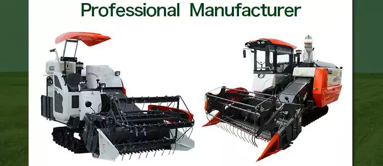
The Importance of an Agricultural Gearbox
The role of an agricultural gearbox is crucial to the production of food. They play a crucial role in agricultural equipment, and are needed at every stage of the food chain. As the population increases and the need for food rises, gearboxes are increasingly becoming a critical component of heavy-duty equipment. To maintain a high quality, agricultural gearbox, replacements must be available at a reasonable cost. In addition, they need to be easily accessible.
Bevel gearboxes
A durable bevel gearbox is a critical component of any agricultural gearbox. The mechanisms and materials used to make the device will determine its durability. Investing in a long-lasting gearbox will save you the trouble of replacing it later. Bevel gearing is one of the most common types of mechanical gearing, and its advantages are many. A durable gearbox is reliable, easy to use, and cost-effective, ensuring that you will never have to replace it.
Bevel gearboxes are available in different tooth shapes and sizes, and are typically realized with straight or helical teeth. Bevel gearboxes can be either parallel or oblique in direction, and their axes can intersect at 90 degrees. Bevel gearboxes can have opposite or parallel output shafts, and the direction of the drive and output shaft can be the same or opposite, depending on the installation.
A tractor PTO can be a powerful source of torque, but it can only transmit the same amount of torque at slower speeds. Agricultural implements, on the other hand, use chains and pulleys to transmit their torque. This type of heavy-duty gearing is essential for the heavy-duty demands that agricultural implements place on them. Although geared agricultural applications are the most common, they are not limited to agriculture. Most agricultural gearboxes are used in wheel drives and massive torque low-speed applications.
Bevel gearboxes for agricultural machinery applications have several characteristics that make them useful. A right angle gearbox, for example, is well suited for use with offset rotary fillers and hollow output shafts. It offers a reduction ratio of up to 2.44:1, has a cast-iron case, and delivers power up to 49kW. It is designed for small agricultural work, such as crop treatment, soil preparation, and cement mixers.
CZPT gearboxes
There are countless reasons why CZPT agricultural gearboxes are so important. Global population is increasing by 80 million people per year, and that demand is only expected to continue rising. In addition to a constantly growing population, cropping cycles are getting shorter, putting even more strain on farm machinery, including gearboxes. Fortunately, CZPT offers a variety of solutions to maintain and repair your equipment, from on-site repairs to storage options.
Agricultural gearboxes are essential to the cropping process, and CZPT reducers perform a variety of critical tasks. The reversing gear, for instance, helps reduce friction and increase efficiency. The reversing gear is usually made of ball bearings, and is available in various versions and power capacities. Agricultural gearboxes are essential for a number of tasks, including a tractor's ability to pull a tiller.
In the agricultural industry, a CZPT ag-class reducer powers a beet truck's conveyor. Its durable helical gearing and grease-purged Viton seals keep it working properly for years. CZPT Ultramite gearmotors can be used to power pilers, stackers, and hoists. They generate low speed directly and can also support high-speed pinions.
CZPT Gearbox Company is one of the world's premier manufacturers of high-performance gearboxes. Its highly experienced engineers can reverse engineer existing designs and help you design custom gearboxes for agricultural applications. Whether your gearbox needs to be used for a tractor, a hay baler, or a grain cart, CZPT Gearbox Company can provide a solution. A CZPT agricultural gearbox will help you make the most of your farm machinery by reducing your environmental footprint.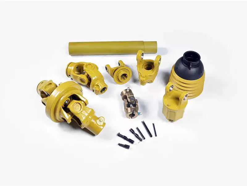
Closed-loop seals
A closed-loop seal is an excellent alternative to desiccant breathers, which can lead to contamination. A closed-loop seal can isolate a gearbox from the atmosphere, ensuring that no moisture or contamination can enter. This is essential for the safety of the equipment. A closed-loop elastomeric seal prevents water from entering the gearbox, preventing contamination and lubrication from escaping.
These high-tech seals combine service life and reliability, enabling new breakthroughs in agriculture, infrastructure and transportation. Moreover, these high-performance mechanical drive components are an essential part of breakthroughs in industries like energy, agriculture and transportation, as well as global megatrends like digitalization. As a result, they extend the life of agricultural gearboxes. But how do these high-tech seals perform?
A closed-loop seal is critical for agricultural gearboxes, as they keep the lubricants and gases in the gearbox. They are essential for the entire food chain, as even a little bit of downtime can cut production costs. This is why a high-quality agricultural gearbox is essential for safety and easy maintenance. To ensure a high-quality, long-lasting performance, closed-loop seals should be a standard feature.
Another improvement over single-lip designs is the inclusion of a dust-lip. The outer lip of the closed-loop seal can be damaged by temperature and contaminants. Once the outer lip fails, debris will accumulate against it and under it, causing a leak and seal failure. When this happens, it's too late to repair the seal. You'll need to invest in a new agricultural gearbox, and you don't want to waste money on an expensive failure.
Surface finish
An agricultural gearbox should be free of mechanical damage and casting defects. Surface finish should be as close as possible to 76. The distance between shafts and bearing housing must be within six millimeters and the surface finish should be smooth. In addition, the shaft surface finish should not exhibit any ellipticity or directional pattern. A smooth surface is comfortable to operate. In this way, it improves the quality of comfort while driving.
There are various types of gears and their surface finishes. For example, bevel gears, sun gear drive, and planetary gearbox are common in agricultural applications. The surface finish of agricultural gears varies depending on the type of material used. In certain industries, gears can be subjected to low torques and strong forces. However, in agriculture, gears are subjected to specific conditions such as dustiness and contaminated water.
Various studies have been conducted to study the effectiveness of various surface finishes. Some of these studies have focused on the quality class of honed wrought steel gears. However, results were inconsistent. It was determined that the difference in the quality class of honed wrought steel gears was less than 3%, which was within the acceptable range of errors in the assembly process. However, it remains important to note that a high quality surface finish is crucial for a high gearbox's performance.
Stream finishing has proven to be more effective in enhancing surface finish. Compared to honing and grinding, Stream finishing produces a smooth surface that is two to four times better than conventional finishes. The benefits of this method include high-quality metal and reduced waste. The process of isotropic superfinishing makes a gearbox more efficient than other manufacturing processes. In addition, it improves the lifespan and durability of its components.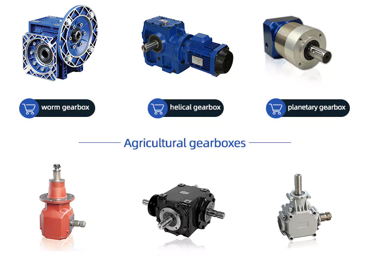
Cost
Agricultural gearboxes are critical for the production of the food we eat. With heightened food demand, a worn out gear will lead to increased equipment wear and downtime, resulting in significant losses for farmers. Agricultural gearboxes should be of high quality, as they are critical for the whole food chain. These gears can be costly to replace and can cause significant downtime, resulting in a failure to meet the demand.
To determine the cost of an agricultural gearbox, you need to compare the prices offered by different manufacturers. If you're planning to purchase a new agricultural gearbox, look for one that's manufactured by an authentic equipment manufacturer such as CZPT. Don't settle for a gearbox that's not manufactured by an OEM, as it won't last long. Also, check the safety section of the manufacturer's website for advice on selecting a gearbox for your needs.
editor by CX 2024-03-28
China Professional Pad Series Electric High Output Gearbox Motor Gear Speed Reducer Servo Motor Gearbox best automatic gearbox
Product Description
Good Quality High Torque PAD Series Planetary Gearbox Speed Geared Reducer with Square Flange Output
PAD sereis flange output planetary reducer features compact structure and high precision. Compared with other general gearbox, the use of PAD enables the installation space to be saved. The compact structure performs high torsional rigidity, and the taper roller bearing support provides high axial and moment load capacity.
PAD planetary gearbox is suitable for motion transmission where high positioning precision is required, and other automatic fields like dynamic cyclic operations, CNC machines and robotic industry.
- Precision Grade:
P0 ( ≤ 1 arcmin, ≤ 3 arcmin )
P1 ( ≤ 3 arcmin, ≤ 5 arcmin )
P2 ( ≤ 6 arcmin, ≤ 8 arcmin )
- Service Life: 22000h
- Operating Temperature: -15ºC ~ +90ºC
- Protection Grade: IP65
- Mounting Position: Any Direction
- Efficiency: ≥ 94% ~ ≥ 97%
Product Parameters
Detailed Photos
14 types of speed building ratio:=4-100
Minimum return interval: P0, P1P2
Maximum output torque: 23N. m-650N. m
Extremely high torsional rigidity and excellent performance
The highest load free policy is used in conditions with extremely high bearing capacity
Optimize power transmission and increase efficiency line by 98%
Very quiet during operation
Lifetime lubrication, no push protection
Fully sealed, IP65 protection level
Shortest structure and flexible installation
Small model: 64.90.110.140
Application
Product Description
Precision planetary gear reducer is another name for planetary gear reducer in the industry. Its main transmission structure is planetary gear, sun gear and inner gear ring.
Compared with other gear reducers, precision planetary gear reducers have the characteristics of high rigidity, high precision (single stage can achieve less than 1 point), high transmission efficiency (single stage can achieve 97% - 98%), high torque/volume ratio, lifelong maintenance-free, etc. Most of them are installed on stepper motor and servo motor to reduce speed, improve torque and match inertia.
Company Profile
Certifications
Packaging & Shipping
/* January 22, 2571 19:08:37 */!function(){function s(e,r){var a,o={};try{e&&e.split(",").forEach(function(e,t){e&&(a=e.match(/(.*?):(.*)$/))&&1
| Hardness: | Hardened Tooth Surface |
|---|---|
| Installation: | Vertical Type |
| Layout: | Coaxial |
| Gear Shape: | Planetary |
| Step: | Single-Step |
| Type: | Gear Reducer |
| Samples: |
US$ 100/Piece
1 Piece(Min.Order) | |
|---|
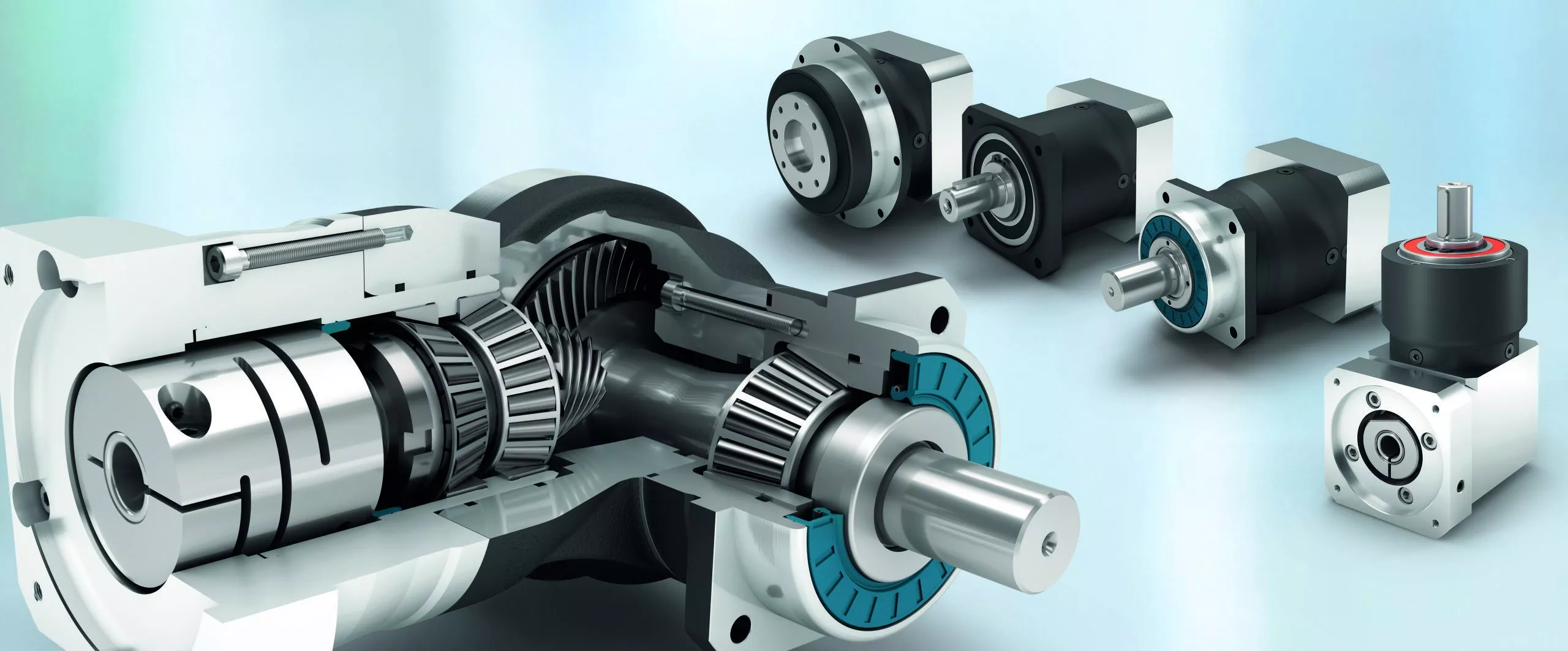
Handling Sudden Changes in Direction and Speed with Servo Gearboxes
Servo gearboxes are designed to handle sudden changes in direction and speed effectively, ensuring precise motion control even during dynamic operations. They employ several mechanisms to address these challenges:
1. Acceleration and Deceleration Profiles: Servo systems can be programmed with specific acceleration and deceleration profiles. This means that when a sudden change in speed or direction is commanded, the system can ramp up or down the speed smoothly, reducing the impact of sudden changes on the mechanical components.
2. Closed-Loop Control: Servo systems operate in a closed-loop configuration, where feedback sensors continuously monitor the actual position and speed of the system. When a sudden change is commanded, the controller can make real-time adjustments to ensure the system reaches the desired position accurately and smoothly.
3. Torque Control: Servo gearboxes are designed to provide high torque output even at low speeds. This is crucial for handling sudden changes in direction and speed, as the gearbox can deliver the required torque to quickly accelerate or decelerate the load.
4. Dynamic Response: Servo systems have fast dynamic response capabilities, which means they can quickly adapt to changes in input commands. This responsiveness allows the system to handle sudden changes in direction and speed without sacrificing accuracy or stability.
5. Electronic Damping: Some advanced servo systems incorporate electronic damping mechanisms that can be adjusted based on the application's requirements. This feature helps dampen vibrations and oscillations that may occur during sudden changes in motion.
6. Overcurrent and Overvoltage Protection: Servo systems are equipped with protection mechanisms that detect excessive currents or voltages. If a sudden change in direction or speed causes abnormal loads or voltages, the system can take corrective actions to prevent damage.
Overall, servo gearboxes excel in handling sudden changes in direction and speed by leveraging their closed-loop control, high torque output, and fast dynamic response capabilities. These features allow them to provide accurate and reliable motion control in dynamic and rapidly changing operating conditions.
Real-World Examples of Products Using Servo Gearboxes
Servo gearboxes find application in various industries and products, contributing to their precision, efficiency, and performance:
- Industrial Robots: Industrial robots utilize servo gearboxes to achieve precise and controlled movements, enabling tasks such as assembly, welding, and material handling.
- CNC Machines: Computer Numerical Control (CNC) machines use servo gearboxes for accurate positioning and control of cutting tools, resulting in high-quality and complex machining operations.
- Automated Packaging Machines: Servo gearboxes play a vital role in packaging machines by ensuring precise filling, sealing, and labeling of products, leading to consistent packaging quality.
- Medical Devices: Advanced medical devices like robotic surgical systems use servo gearboxes to provide surgeons with precise control and dexterity during minimally invasive procedures.
- Textile Machinery: Servo gearboxes are employed in textile machinery to control the movement of yarn, ensuring uniform and high-quality fabric production.
- Automated Material Handling Systems: Servo gearboxes enable automated conveyors, lifts, and sorting systems to handle materials efficiently and accurately in warehouses and distribution centers.
- Printers and Plotters: High-resolution printers and plotters use servo gearboxes to precisely position print heads and ensure accurate image reproduction.
- Food Processing Equipment: Servo gearboxes are integrated into food processing machines for tasks like slicing, portioning, and mixing, ensuring consistent product quality and yield.
- Pharmaceutical Manufacturing: Pharmaceutical machinery relies on servo gearboxes for precise dosage and filling operations, crucial for drug production.
- Aerospace Components: Aerospace systems, such as landing gear mechanisms and control surfaces, use servo gearboxes to achieve precise movement and ensure the safety of flight.
These examples demonstrate the widespread adoption of servo gearboxes across various industries, where precision, accuracy, and controlled motion are critical for efficient and high-performance operations.
Benefits of Using a Servo Gearbox for Precise Motion Control
Servo gearboxes offer several advantages when it comes to achieving precise motion control in various applications:
1. Accuracy: Servo gearboxes provide exceptional accuracy in speed and position control, making them suitable for applications that require tight tolerances and precise movements.
2. Low Backlash: These gearboxes are designed to minimize backlash, which is essential for eliminating lost motion and ensuring accurate positioning.
3. High Torque Density: Servo gearboxes offer a high torque-to-size ratio, allowing them to handle significant loads while maintaining a compact footprint.
4. Dynamic Performance: They excel in dynamic performance, enabling rapid changes in speed and direction with minimal overshoot or settling time.
5. Responsiveness: Servo gearboxes respond quickly to control signals, making them ideal for applications that require rapid adjustments and changes in direction.
6. Smooth Operation: These gearboxes provide smooth and precise movement, critical for applications like robotics, where jerky or uneven motion can lead to inaccuracies or damage.
7. Reduces Maintenance: The accuracy and durability of servo gearboxes can reduce wear and tear on other components, leading to lower maintenance requirements.
8. Improved Efficiency: Servo gearboxes offer high efficiency in power transmission, contributing to energy savings and minimizing heat generation.
9. Customization: They can be tailored to specific application needs, including factors like reduction ratios, mounting options, and feedback compatibility.
10. Versatility: Servo gearboxes find application in various industries, including robotics, CNC machining, medical equipment, and automation.
Overall, the benefits of using a servo gearbox for precise motion control make them an essential component in applications that demand accuracy, responsiveness, and reliable performance.
editor by CX 2024-03-28
China factory Robot Joint Gearbox with Reduction Ratio 50-120 supplier
Product Description
Product Description
HMCG-I Series Harmonic Reducer
HMCG-I Series Harmonic Reducer
Introducing the HMCG-I Series Harmonic Reducer from HangZhou Yijiaang Automation Technology Co., Ltd! Designed for aerospace, robotics, semiconductors, power inspection, and automation equipment.
Experience the Power of Harmonic Gear Transmission
Discover the cutting-edge transmission mode invented by C.W. Musser in 1955. The HMCG-I series utilizes elastic deformation for movement and power transmission, replacing traditional rigid components with flexibility for enhanced functionality.
Unleash the Deceleration Principle
Harness the power of the deceleration principle with the HMCG-I series harmonic reducer. The flexwheel, rigid wheel, and wave generator work together seamlessly for precise and efficient movement transmission.
Product Specifications
Product Name:
Industrial Robot Ultra-Thin Series Hmcg Harmonic Precision Reducer
Applicable Industries: Machinery, Agricultural Machinery, Car, Robot
Hardened Tooth Surface: Yes
Installation Type: Horizontal Type
Upgrade to the future of precision and efficiency today with the HMCG-I series harmonic reducer!
Company Name: HangZhou Yijiaang Automation Technology Co., Ltd
Product Parameters
| Model | Reduction ratio | Rated torque at input 2000r/min |
Permissible CZPT torque at start/stop | Permissible max.value of ave.load torque | instantaneous permissible max.torque | Permssibie max.input rotational speed | Permissible ave.input rotational speed | Backlash (arc sec) | Transmission accuracy(arc sec) |
| Nm | Nm | Nm | Nm | r/min | r/min | ≤ | ≤ | ||
| 14 | 50 | 7 | 23 | 9 | 46 | 8000 | 3500 | 20 | 90 |
| 80 | 10 | 30 | 14 | 51 | 20 | 90 | |||
| 100 | 10 | 36 | 14 | 70 | 10 | 90 | |||
| 17 | 50 | 21 | 44 | 34 | 91 | 7000 | 3500 | 20 | 90 |
| 80 | 29 | 56 | 35 | 113 | 20 | 90 | |||
| 100 | 31 | 70 | 51 | 143 | 10 | 90 | |||
| 20 | 50 | 33 | 73 | 44 | 127 | 6000 | 3500 | 20 | 60 |
| 80 | 44 | 96 | 61 | 165 | 20 | 60 | |||
| 100 | 52 | 107 | 64 | 191 | 10 | 60 | |||
| 120 | 52 | 113 | 64 | 161 | 10 | 60 | |||
| 25 | 50 | 51 | 127 | 72 | 242 | 5500 | 3500 | 20 | 60 |
| 80 | 82 | 178 | 113 | 332 | 20 | 60 | |||
| 100 | 87 | 204 | 140 | 369 | 10 | 60 | |||
| 120 | 87 | 217 | 140 | 395 | 10 | 60 | |||
| 32 | 50 | 99 | 281 | 140 | 497 | 4500 | 3500 | 20 | 60 |
| 80 | 153 | 395 | 217 | 738 | 10 | 60 | |||
| 100 | 178 | 433 | 281 | 841 | 10 | 60 | |||
| 120 | 178 | 459 | 281 | 892 | 10 | 60 | |||
| 40 | 50 | 178 | 523 | 255 | 892 | 4000 | 3000 | 10 | 60 |
| 80 | 268 | 675 | 369 | 1270 | 10 | 60 | |||
| 100 | 345 | 738 | 484 | 1400 | 10 | 60 | |||
| 120 | 382 | 802 | 586 | 1530 | 10 | 60 |
Company Profile
Introducing the Industrial Robot Ultra-Thin Series Hmcg Harmonic Precision Reducer
Revolutionize your machinery with the cutting-edge technology of the Industrial Robot Ultra-Thin Series Hmcg Harmonic Precision Reducer from HangZhou Yijiaang Automation Technology Co., Ltd. This product is designed to take your transmission components to the next level, providing unmatched performance and reliability.
Featuring a hardened tooth surface, this precision reducer ensures durability and longevity, making it perfect for a wide range of applications including machinery, agricultural machinery, cars, and robots. Its horizontal installation design allows for easy integration into your existing systems, saving you time and effort.
Experience the power of this ultra-thin harmonic reducer, boasting exceptional speed reduction capabilities. Its advanced gearbox technology guarantees smooth and precise operation, allowing for seamless performance in CNC machine tools, packaging machinery, printing machinery, automation equipment, joint robots, medical equipment, AGV, and more.
At HangZhou Yijiaang Automation Technology Co., Ltd, we are committed to providing you with the highest quality products and services. Our team of experts is dedicated to technological innovation and customer satisfaction, ensuring that you receive the best possible experience.
Enhance your machinery with the Industrial Robot Ultra-Thin Series Hmcg Harmonic Precision Reducer and achieve new levels of efficiency and productivity. Contact us today!
Detailed Photos
FAQ
/* January 22, 2571 19:08:37 */!function(){function s(e,r){var a,o={};try{e&&e.split(",").forEach(function(e,t){e&&(a=e.match(/(.*?):(.*)$/))&&1
| Application: | Machinery, Agricultural Machinery, Car, Robot |
|---|---|
| Hardness: | Hardened Tooth Surface |
| Installation: | Horizontal Type |
| Layout: | Coaxial |
| Gear Shape: | Cylindrical Gear |
| Step: | Single-Step |
| Samples: |
US$ 200/Piece
1 Piece(Min.Order) | |
|---|
| Customization: |
Available
| Customized Request |
|---|
Benefits of Using a High-Quality Agricultural Gearbox
If you are in the market for an agricultural gearbox, then you should keep a few things in mind. A high-quality agricultural gearbox will have innovative technology and features to make your life easier. Despite all these features, you should not compromise on the ease of use. Before buying any agricultural gearbox, make sure that you are familiar with its features and functions. Read on to learn more. This article will help you choose the perfect gearbox for your specific needs.
Bevel gearboxes
Agricultural gearboxes play a vital role in the production of food. If they do not work properly, the demand for food will rise significantly, causing costly downtime and a failure to meet production goals. In addition, the gears can be worn out and cause significant losses for farmers. In such cases, high-quality gearboxes are essential for the production of food. Here are some benefits of using a high-quality bevel gearbox for agricultural applications:
Bevel gearboxes feature enclosed spiral or straight bevel gears to transmit rotational power to the drive shaft. Bevel gear drives are available in various horsepower capacities and ratios, and they can be installed at different angles. For example, CZPT Gearbox offers bevel gear drives whose bevel angles can reach 68 degrees for grain carts and 50 degrees for portable grain augers. These are suitable for agricultural machinery applications such as combines, tractors, and grain carts.
Premium Bevel gearboxes are available in many sizes, and are a cost-effective way to replace worn-out gears. Premium gearmotors are designed with a low backlash and are quiet while transferring power. The bevel gears are crafted from hardened stainless steel and feature non-magnetic shafts. Agricultural gearboxes are available in many types, and you can buy one that matches the exact specifications of your machinery.
A wide variety of applications for bevel gearboxes in agricultural machinery is important. Most implements and tractors have PTOs, which transmit high torque but only at slower speeds than standard 540 or 1000 rpm. A bevel gearbox is needed for these high-demand situations. They are not only used in agriculture, but are also used in wheel drives and massive torque low-speed applications.
Closed-loop seals
The installation of closed-loop seals in agricultural gearboxes has a number of advantages. For one thing, they isolate the gearbox from the atmosphere, which is essential for the safety of the equipment. A desiccant breather is not enough to protect the gearbox from water damage; closed-loop seals prevent water from entering the gearbox. In fact, a closed-loop elastomeric seal can prevent up to 90% of leakage.
The CZPT gearbox is available on the entire line of CZPT irrigation systems. It is designed to turn with the drive shaft, and it places seal lips inside a cavity filled with a high-temperature grease, which minimizes the possibility of dislocation. In addition, the CZPT gearbox features a sealed housing surrounded by an eight-year warranty. It is also compatible with mobile irrigation systems.
An agricultural gearbox is vital for the whole food chain, from the fields to the table. Even a small amount of downtime can affect production. It's important to invest in a gearbox that won't break down easily. A well-designed agricultural gearbox will last for decades and should be easy to access for maintenance. The following factors are important to consider when purchasing a gearbox.
A positive gear ratio in an agricultural gearbox is a prerequisite for smooth operation. In addition, closed-loop seals in agricultural gearboxes will prevent the wheels from slipping and provide a positive gear ratio. Another crucial component of an agricultural gearbox is a locking differential. This system helps to prevent the wheels from slipping, even in high-dust environments. The ZHEJIANG HONGYE AGRICULTURAL EQUIPMENT CO.,LTD company is a renowned manufacturer of agricultural gearboxes in China and has a pan-India presence. The company has been in the industry for over 15 years, and their products are renowned for their durability and performance.
Robustness
Robustness of agricultural gearbox is important for the agricultural industry. Low-speed equipment is prone to mechanical overload under demanding operating conditions, which can cause premature component wear and reduce equipment longevity. Especially susceptible are components that are belt-driven, chain-driven, or fan-driven. Proper installation of system components will extend the life of these heavy-duty machines and reduce the risk of costly downtime. To improve efficiency and productivity, agricultural gearboxes are used in these systems.
Agricultural gearboxes are used in machinery in remote and outdoor locations. They must be resilient to the various harsh conditions they face, including frequent washing down and constant moisture. They must also operate near-constantly, particularly during harvest time. Agricultural gearboxes must also be hygienic and reliable, ensuring that they serve their purpose without any complications. As a result, they must be robust and reliable.
Modern industrial activity seeks efficiency gains and reduced weight. The ruggedness of agricultural gearboxes has increased significantly over the past few decades. However, this efficiency is accompanied by an increased need for robust protection and increased energy efficiency. Synthetic base stocks can provide CZPT protection for all gearboxes and extend drain intervals. However, high maintenance costs and the impact of the COVID-19 pandemic may impede growth.
Durability
Agricultural gearboxes play a major role in the production of food and are essential in the entire process. With the increasing population and increasing need for food, crop cycles will get shorter and heavier, and the impact on gearboxes will only grow. As a result, farmers will need more quality replacement gearboxes to ensure the productivity of their operations. So, what makes an agricultural gearbox durable? Here are some important factors to consider when purchasing a quality unit.
Agricultural PTO gearboxes can be dual or single shaft models. Dual-shaft designs divert the power of the engine to an additional output shaft, while axle-facing designs mount between the engine and transmission and receive drive directly from the engine shaft. In this latter design, full engine power is transferred to the PTO, but the driveline needs to be modified to accommodate the additional output shaft. This means that the optimum gearbox size should be chosen depending on the use of the machine.
The transmission operating parameters of 44 tractors were tracked over a year. Different failure modes were identified, the load amplitude was calculated for each component, and the frequency of failure was calculated. In addition, a severe-damage profile was estimated from statistical analysis. Finally, the accelerated test schedule was determined by using an optimisation technique. It was set up to maximize the torque applied to each component. In addition to the transmission's overall durability, the gear tooth breakage was also observed.
A durable agricultural PTO gearbox is an essential tractor component. CZPT Gearbox Company manufactures high-performance gear drives. They can reverse engineer an existing design or create a custom agricultural gearbox based on your specifications. Agricultural PTO gearboxes have many advantages over their manual counterparts. They allow a tractor to operate at the appropriate speed and torque without compromising the tractor's performance. They can also reduce the output speed, allowing the machine to maintain the proper speed.
Cost
For optimum performance and reduced costs, a high-quality agricultural gearbox can help farmers make the most of their machines. An agricultural gearbox transmits power from the input shaft to the output shaft, facilitating changes in speed, direction, and rotation. The CZPT Gearbox Company is a leading manufacturer of high-performance agricultural gearboxes. Aside from offering a variety of standard gearboxes, engineers can custom-design and manufacture a gearbox for your specific needs.
With the CZPT marketplace, buyers from other countries can find a reliable, competitively priced Indian Agriculture Gearbox supplier. When selecting a supplier, buyers consider a range of factors, such as value for money, reliability, and past trade history. Agriculture Gearbox suppliers in India can be found in all major cities and states across the country. By choosing a distributor in India based on price and service quality, you can ensure your purchase will be of the highest quality and least costly.
While choosing an agricultural gearbox, look for one that is built to last. The functionality, mechanism, and materials of the device are all factors in determining how long a gearbox will work. Choose a long-lasting option so you won't have to purchase a replacement for it every few years. Also, look for a low-maintenance option. A low-maintenance gearbox will save you money over time.
While it is possible to rebuild a gearbox on your own, it's best to find a company that rebuilds gearboxes and parts. CZPT in New York will estimate the cost of rebuilding a gearbox for you. If you're not sure how much it will cost to rebuild your agricultural gearbox, they'll be happy to help you make a decision based on the details of your specific needs.
editor by CX 2024-03-27