Product Description
Product Description
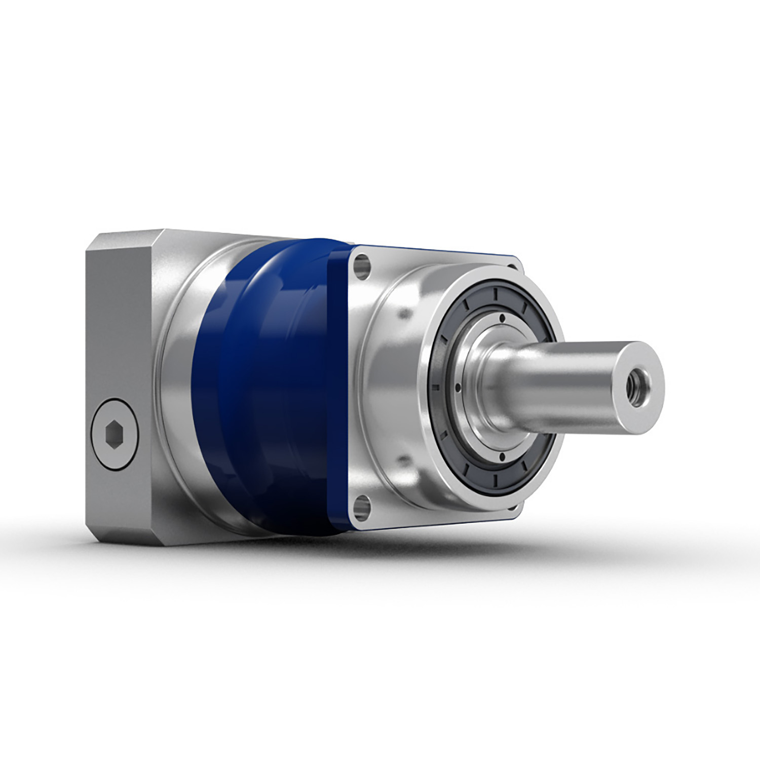
The ND047A series planetary gearboxes are designed and machined as a single unit with special tapered roller bearings to provide high radial load, high torque, ultra-precision, and small size. The ND series uses in highly rigid industries such as fiber optic laser equipment, floor track equipment, robot seventh axis, Parallel robots (spider hand) machine tools, and rotating arms.
Product Name: High Precision Planetary Reducer
Product Series: ND047A Series
Product features: high torque, high load, ultra-precision, small size
Product Description:
Integrated design concept with high-strength bearings ensure the product itself is durable and efficient
A variety of output ideas such as shaft output, flange and gear are available.
1 arc minute ≤ backlash ≤ 3 arc minutes
Reduction ratios ranging from 3 to 100
Frame design: increases torque and optimizes power transmission
Optimised selection of oil seals: reduces friction and laminate transmission efficiency
Protection class IP65
Warranty: 2 years
Our Advantages
High torque
High load
ultra-precision
Small size
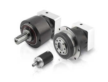
Detailed Photos
Product Parameters
| Segment number | Double segment | ||||||||
| Ratio | i | 16 | 20 | 25 | 35 | 40 | 50 | 70 | 100 |
| Rated output torque | Nm | 18 | 18 | 20 | 18 | 18 | 20 | 18 | 13 |
| Emergency stop torque | Nm | Three times of Maximum Output Torque | |||||||
| Rated input speed | Rpm | 5000 | |||||||
| Max input speed | Rpm | 10000 | |||||||
| Ultraprecise backlash | arcmin | / | |||||||
| Precision backlash | arcmin | ≤5 | |||||||
| Standard backlash | arcmin | ≤7 | |||||||
| Torsional rigidity | Nm/arcmin | 7 | |||||||
| Max.bending moment | Nm | 42.5 | |||||||
| Max.axial force | N | 990 | |||||||
| Service life | hr | 20000(10000 under continuous operation) | |||||||
| Efficiency | % | ≥97% | |||||||
| Weight | kg | 1 | |||||||
| Operating Temperature | ºC | -10ºC~+90ºC | |||||||
| Lubrication | Synthetic grease | ||||||||
| Protection class | IP64 | ||||||||
| Mounting Position | All directions | ||||||||
| Noise level(N1=3000rpm,non-loaded) | dB(A) | ≤56 | |||||||
| Rotary inertia | Kg·cm² | 0.03 | |||||||
Applicable Industries
Packaging Machinery Mechanical Hand Textile Machinery
Non Standard automation Machine Tool Printing Equipment /* January 22, 2571 19:08:37 */!function(){function s(e,r){var a,o={};try{e&&e.split(",").forEach(function(e,t){e&&(a=e.match(/(.*?):(.*)$/))&&1
| Application: | Motor, Machinery, Marine, Agricultural Machinery, CNC Machine |
|---|---|
| Function: | Change Drive Torque, Speed Changing, Speed Reduction |
| Layout: | Plantery Type |
| Hardness: | Hardened Tooth Surface |
| Installation: | All Directions |
| Step: | Double-Step |
| Customization: |
Available
| Customized Request |
|---|

The Role of Harmonic Drive Servo Gearboxes in Advanced Motion Control Systems
Harmonic Drive servo gearboxes play a crucial role in advanced motion control systems by offering several unique features:
1. High Precision: Harmonic Drive gearboxes are known for their exceptional precision due to the unique gear mechanism they employ. This precision is essential for achieving accurate and repeatable motion control.
2. Zero Backlash: Harmonic Drive gearboxes are designed with zero backlash, which means there is no lost motion between input and output. This feature ensures that the commanded motion is precisely transferred without any delays or inaccuracies.
3. Compact Design: Harmonic Drive gearboxes have a compact structure, making them suitable for applications with limited space. The compact design allows for easy integration into various systems.
4. High Torque Transmission: Despite their compact size, harmonic drive gearboxes can transmit high torque efficiently. This feature is essential for applications that require both high precision and high torque.
5. Smooth Motion: The unique wave generator mechanism in harmonic drive gearboxes contributes to smooth and continuous motion, which is particularly beneficial in applications involving robotic arms, satellite positioning, and more.
6. Reduction Ratios: Harmonic Drive gearboxes offer high reduction ratios in a single-stage, allowing for precise control of output motion even when input motion is at high speeds.
7. Low Maintenance: The absence of backlash and the use of high-quality materials result in reduced wear and maintenance requirements, enhancing the longevity of the gearbox.
8. Advanced Applications: Harmonic Drive gearboxes are commonly used in robotics, aerospace, medical equipment, automation, and other industries where precision and reliability are paramount.
Overall, harmonic drive servo gearboxes are a critical component in achieving advanced motion control, enabling engineers to design and operate complex systems with unparalleled precision and accuracy.

Considerations for Selecting the Right Servo Gearbox for an Application
Choosing the appropriate servo gearbox for a specific application requires careful evaluation of several key factors:
1. Torque and Speed Requirements: Determine the required torque and speed characteristics of the application, ensuring that the chosen servo gearbox can provide the necessary output.
2. Gear Ratio: Calculate the ideal gear ratio based on the desired motion profile, acceleration, and deceleration requirements.
3. Mounting and Integration: Consider the available space and mechanical layout of the machinery to choose a servo gearbox with the appropriate mounting configuration.
4. Motor Compatibility: Ensure that the servo gearbox is compatible with the specific type and size of motor being used for the application.
5. Precision and Accuracy: Evaluate the level of precision required for the application's motion control. Choose a servo gearbox that can deliver the necessary accuracy and repeatability.
6. Load Distribution: Analyze how the load will be distributed among the gears to prevent excessive wear and ensure optimal performance.
7. Backlash and Compliance: Consider the application's tolerance for backlash and compliance. Choose a servo gearbox with low backlash if precise positioning is essential.
8. Environmental Conditions: Factor in the environmental conditions of the application, such as temperature, humidity, and exposure to contaminants. Choose a servo gearbox with suitable sealing and protection.
9. Lubrication: Determine the lubrication requirements of the gearbox and select a model that aligns with the application's maintenance practices.
10. Overload and Shock: Consider potential overload and shock conditions the gearbox may experience. Choose a servo gearbox that can handle sudden changes in load without compromising performance.
11. Feedback Devices: If precise motion control is required, choose a servo gearbox that is compatible with the desired feedback devices, such as encoders or resolvers.
12. Efficiency: Evaluate the efficiency of the servo gearbox to ensure that it contributes to the overall energy efficiency of the system.
13. Service and Support: Select a reputable manufacturer that offers reliable technical support, documentation, and post-purchase services.
14. Budget: Balance the performance requirements of the application with the available budget to make an informed decision.
By carefully considering these factors, engineers and designers can confidently choose the right servo gearbox that meets the specific needs of their application, optimizing performance and productivity.

Benefits of Using a Servo Gearbox for Precise Motion Control
Servo gearboxes offer several advantages when it comes to achieving precise motion control in various applications:
1. Accuracy: Servo gearboxes provide exceptional accuracy in speed and position control, making them suitable for applications that require tight tolerances and precise movements.
2. Low Backlash: These gearboxes are designed to minimize backlash, which is essential for eliminating lost motion and ensuring accurate positioning.
3. High Torque Density: Servo gearboxes offer a high torque-to-size ratio, allowing them to handle significant loads while maintaining a compact footprint.
4. Dynamic Performance: They excel in dynamic performance, enabling rapid changes in speed and direction with minimal overshoot or settling time.
5. Responsiveness: Servo gearboxes respond quickly to control signals, making them ideal for applications that require rapid adjustments and changes in direction.
6. Smooth Operation: These gearboxes provide smooth and precise movement, critical for applications like robotics, where jerky or uneven motion can lead to inaccuracies or damage.
7. Reduces Maintenance: The accuracy and durability of servo gearboxes can reduce wear and tear on other components, leading to lower maintenance requirements.
8. Improved Efficiency: Servo gearboxes offer high efficiency in power transmission, contributing to energy savings and minimizing heat generation.
9. Customization: They can be tailored to specific application needs, including factors like reduction ratios, mounting options, and feedback compatibility.
10. Versatility: Servo gearboxes find application in various industries, including robotics, CNC machining, medical equipment, and automation.
Overall, the benefits of using a servo gearbox for precise motion control make them an essential component in applications that demand accuracy, responsiveness, and reliable performance.


editor by CX 2024-04-02
China Custom Ncj Series Helical Gearbox with Dual Voltage Motor gearbox drive shaft
Product Description
Starshine Drive NCJ Series Helical Geared Motor
Features:
- High efficiency and energy saving: low energy, low noise, small vibration, low temperature rise, wide output speed, and high efficiency: 92%-96%.
- With wide variable range of voltage and frequency motor from 20HZ to 60HZ, and voltage from 320V to 420V.
- Modular design with strong interchangeability.
- Iron or aluminum casting house, good rigidity, high strength and excellent heat-loss.
- Advanced design: gear pair processed by carburizing and quenching heat treatment, and unique low noise gear tooth design to ensure the service life.
- Free maintenance: special lubrication to guarantee normal running for 20,000 hours without oil replacement;
- Easy replacement: can replace cycloid gearbox and upgrade product
Technical Parameters
| Type | Old Type | Output Torque | Output Shaft Dia. |
| SNR02 | NCJ02 | 130N.m | φ22 |
| SNR03 | NCJ03 | 250N.m | φ28 |
| SNR04 | NCJ04 | 500N.m | φ32 |
| SNR05 | NCJ05 | 750N.m | φ40 |
| SNRW03Y | NCJT03Y2 | 250N.m | φ35 |
| SNRL04Y | NCJF04Y2 | 450N.m | φ35 |
About Us
ZheJiang CHINAMFG Drive Co.,Ltd(Starshine) have a strong technical force with over 350 employees at present, including over 30 engineering technicians, 30 quality inspectors, covering an area of 80000 square CHINAMFG and kinds of advanced processing machines and testing equipments. We have a good foundation for the industry application development and service of high-end speed reducers & variators owning to the provincial engineering technology research center,the lab of gear speed reducers, and the base of modern R&D.
Our Team
Quality Control
Quality:Insist on Improvement,Strive for CHINAMFG With the development of equipment manufacturing indurstry,customer never satirsfy with the current quality of our products,on the contrary,wcreate the value of quality.
Quality policy:to enhance the overall level in the field of power transmission
Quality View:Continuous Improvement , pursuit of excellence
Quality Philosophy:Quality creates value
3. Incoming Quality Control
To establish the AQL acceptable level of incoming material control, to provide the material for the whole inspection, sampling, immunity. On the acceptance of qualified products to warehousing, substandard goods to take return, check, rework, rework inspection; responsible for tracking bad, to monitor the supplier to take corrective measures to prevent recurrence.
4. Process Quality Control
The manufacturing site of the first examination, inspection and final inspection, sampling according to the requirements of some projects, judging the quality change trend; found abnormal phenomenon of manufacturing, and supervise the production department to improve, eliminate the abnormal phenomenon or state.
5. FQC(Final QC)
After the manufacturing department will complete the product, stand in the customer's position on the finished product quality verification, in order to ensure the quality of customer expectations and needs.
6. OQC(Outgoing QC)
After the product sample inspection to determine the qualified, allowing storage, but when the finished product from the warehouse before the formal delivery of the goods, there is a check, this is called the shipment inspection.Check content:In the warehouse storage and transfer status to confirm, while confirming the delivery of the product is a product inspection to determine the qualified products.
7. Certificate: all of our products pass ISO, CE certificate.
Packing
Delivery
/* January 22, 2571 19:08:37 */!function(){function s(e,r){var a,o={};try{e&&e.split(",").forEach(function(e,t){e&&(a=e.match(/(.*?):(.*)$/))&&1
| Application: | Motor, Machinery, Agricultural Machinery |
|---|---|
| Function: | Speed Changing, Speed Reduction |
| Layout: | Coaxial |
| Hardness: | Hardened Tooth Surface |
| Installation: | Horizontal Type |
| Step: | Single-Step |
| Customization: |
Available
| Customized Request |
|---|
High-Speed Applications and Accuracy in Servo Gearboxes
Servo gearboxes can indeed be used in high-speed applications without compromising accuracy, thanks to their design features:
1. Precision Engineering: Servo gearboxes are engineered with high precision, which allows them to maintain accurate motion control even at high speeds.
2. Reduced Backlash: Many servo gearbox designs incorporate mechanisms to minimize backlash, which is the lost motion between input and output. This feature enhances accuracy even in high-speed scenarios.
3. Advanced Bearings: High-quality bearings used in servo gearboxes reduce friction and contribute to maintaining accuracy and efficiency at high speeds.
4. Rigid Construction: The rigid construction of servo gearboxes minimizes flexing or deformation under high-speed loads, ensuring that the intended motion is accurately transmitted.
5. Dynamic Balancing: Some servo gearboxes are dynamically balanced to minimize vibrations that could affect accuracy during high-speed operation.
6. Lubrication: Proper lubrication practices play a vital role. The right lubricant minimizes friction, heat, and wear, ensuring accuracy even at high speeds.
7. Feedback Systems: High-speed applications often use feedback systems, such as encoders, to constantly monitor and adjust the positioning. This further enhances accuracy.
8. Advanced Control Algorithms: The combination of accurate gearboxes and advanced control algorithms ensures precise motion profiles even at high speeds.
Overall, servo gearboxes are designed to excel in accuracy, precision, and efficiency, making them suitable for high-speed applications where maintaining accuracy is crucial.
Contribution of Servo Gearboxes to Smooth Acceleration and Deceleration
Servo gearboxes play a crucial role in ensuring smooth acceleration and deceleration of machinery in motion control systems:
1. Precise Control: Servo gearboxes provide precise control over the rotational speed and torque of the output shaft. This control allows for gradual and controlled changes in speed, resulting in smooth acceleration and deceleration.
2. Feedback Mechanism: Servo systems typically incorporate feedback devices such as encoders or resolvers. These devices continuously monitor the actual position and speed of the output shaft and provide real-time feedback to the controller. This feedback enables the controller to adjust the input signals to the servo gearbox, ensuring accurate and smooth motion transitions.
3. Dynamic Response: Servo gearboxes are designed for high dynamic response, meaning they can quickly adjust their speed and torque based on the controller's commands. This responsiveness allows for rapid and smooth changes in speed and direction without sudden jerks or jolts.
4. Programmable Profiles: Many servo systems offer the capability to program acceleration and deceleration profiles. Engineers can define specific acceleration and deceleration curves tailored to the application's requirements. These profiles ensure that the machinery achieves the desired speed changes gradually and smoothly.
5. Reduced Wear and Tear: The controlled and gradual acceleration and deceleration provided by servo gearboxes reduce the wear and tear on mechanical components. Sudden changes in speed can lead to shock loads and vibration, potentially damaging the machinery. Servo gearboxes help mitigate these effects, extending the lifespan of components.
6. Increased Productivity: Smooth acceleration and deceleration reduce the chances of product damage, improve product quality, and enhance the overall efficiency of the process. This is particularly important in applications where precise motion control is critical.
Overall, servo gearboxes contribute to the seamless acceleration and deceleration of machinery by providing accurate control, dynamic responsiveness, and programmable motion profiles. These features ensure that machinery can achieve the desired speed changes while maintaining precision, efficiency, and longevity.
Benefits of Using a Servo Gearbox for Precise Motion Control
Servo gearboxes offer several advantages when it comes to achieving precise motion control in various applications:
1. Accuracy: Servo gearboxes provide exceptional accuracy in speed and position control, making them suitable for applications that require tight tolerances and precise movements.
2. Low Backlash: These gearboxes are designed to minimize backlash, which is essential for eliminating lost motion and ensuring accurate positioning.
3. High Torque Density: Servo gearboxes offer a high torque-to-size ratio, allowing them to handle significant loads while maintaining a compact footprint.
4. Dynamic Performance: They excel in dynamic performance, enabling rapid changes in speed and direction with minimal overshoot or settling time.
5. Responsiveness: Servo gearboxes respond quickly to control signals, making them ideal for applications that require rapid adjustments and changes in direction.
6. Smooth Operation: These gearboxes provide smooth and precise movement, critical for applications like robotics, where jerky or uneven motion can lead to inaccuracies or damage.
7. Reduces Maintenance: The accuracy and durability of servo gearboxes can reduce wear and tear on other components, leading to lower maintenance requirements.
8. Improved Efficiency: Servo gearboxes offer high efficiency in power transmission, contributing to energy savings and minimizing heat generation.
9. Customization: They can be tailored to specific application needs, including factors like reduction ratios, mounting options, and feedback compatibility.
10. Versatility: Servo gearboxes find application in various industries, including robotics, CNC machining, medical equipment, and automation.
Overall, the benefits of using a servo gearbox for precise motion control make them an essential component in applications that demand accuracy, responsiveness, and reliable performance.
editor by CX 2024-03-26
China Custom China High Motion Accuracy Motor Reducer Hydraulic Gearbox Cycloidal Gear Reducer cvt gearbox
Product Description
Product Description
China high motion accuracy motor reducer hydraulic gearbox cycloidal gear reducer
motor reducer hydraulic gearbox cycloidal gear reducer
Installed with radial thrust ball bearings, so it can support external load, torque rigidity, large allowable torque, can reduce the number of components required, easy installation. The revolution speed of WRV gears is slower and vibration is reduced, which can reduce the motor structure (input gear) and inertia.
HangZhou Fubao Electromechanical Technology Co., Ltd.motor reducer hydraulic gearbox cycloidal gear reducer High precision, high rigidity, high torque, high load and other characteristics realize hollow design at the same time. After being hollowed out, the ease of use of the product is improved due to the variety of piping and cable layout options.
motor reducer hydraulic gearbox cycloidal gear reducer features:
A. Hollow mechanism
1. Cables can be inserted inside the reducer;
2. The space-saving design of the device is realized.
B. Main bearing built-in mechanism
1. Improved reliability;
2. Total cost reduction;
3. Radial thrust ball bearings are installed, so they can support external loads. High rigidity and large bending moment bearing capacity make it suitable for rotating shafts;
4. It can reduce the number of components required;
5. Easy to install.
C, 2-stage deceleration mechanism
1. Small vibration;
2. Small Gd2;
2. The revolution speed of the gear is slowed down, the vibration is reduced, and the direct connection part of the motor (input gear) can be reduced, and the inertia can be reduced.
D. Double-column support mechanism
1. High torsional rigidity;
2. Small vibration;
3. Strong impact resistance (500% of rated torque);
4. The crank shaft is supported by double columns in the reducer.
E. Rolling contact mechanism
1. Excellent starting power;
2. Small abrasion and long service life;
3. Small backlash (1arc.min);
4. Use rolling bearings.
F. Pin gear mechanism
1. WRV gears and pins have many meshes at the same time.
Product Parameters
| WRV-C(Hollow type) | Specifications | WRV-10C | WRV-27C | WRV-50C | WRV-100C | WRV-200C | WRV-320C | WRV-500C |
| Rated output torque | 686 | 980 | 1764 | 2450 | 8820 | 2 0571 | 34300 | |
| Reduction ratio | 27 | 36.57 | 32.54 | 36.75 | 34.86 | 35.61 | 37.34 | |
| Backlash | <=1 | |||||||
Detailed Photos
Application Case
Company Profile
HangZhou Fubao Electromechanical Technology Co., Ltd. was established in 2008, the company has a complete precision reducer design, production capacity. Set R & D, manufacturing, assembly and sales, more in the field of gear manufacturing has more than 10 years of background, in the manufacturing equipment is equipped with Switzerland Riesenhahl gear grinding machine, domestic Qinchuan gear grinding machine, hamai gear hobbing machine and domestic Xihu (West Lake) Dis. gear hobbing machine, Japan Yasaki TLGmazak CNC lathe, CNC milling machine and other fully CNC equipment, In addition, it is equipped with other advanced measuring equipment such as Japanese TTI gear detector, 3 coordinate measurement, reducer backlash measurement instrument and so on. In a strong manufacturing capacity at the same time, can be stable, continuous manufacturing of high-quality precision reducer products.
The precision reducer produced by our company has the characteristics of high structural rigidity, small back backlash, precise transmission and so on. It is widely used in various industries. Companies adhering to the concept of let customers participate in manufacturing, and strive to provide customers with more personalized services. In the field of precision transmission has a unique achievements. It is our CHINAMFG pursuit to make far-reaching contributions.
Factory Display
FAQ
Q: Speed reducer grease replacement time
A: When sealing appropriate amount of grease and running reducer, the standard replacement time is 20000 hours according to the aging condition of the grease. In addition, when the grease is stained or used in the surrounding temperature condition (above 40ºC), please check the aging and fouling of the grease, and specify the replacement time.
Q: Delivery time
A: Fubao has 2000+ production base, daily output of 1000+ units, standard models within 7 days of delivery.
Q: Reducer selection
A: Fubao provides professional product selection guidance, with higher product matching degree, higher cost performance and higher utilization rate.
Q: Application range of reducer
A: Fubao has a professional research and development team, complete category design, can match any stepping motor, servo motor, more accurate matching. /* March 10, 2571 17:59:20 */!function(){function s(e,r){var a,o={};try{e&&e.split(",").forEach(function(e,t){e&&(a=e.match(/(.*?):(.*)$/))&&1
| Application: | Motor, Machinery, Agricultural Machinery, Robot Arm |
|---|---|
| Function: | Distribution Power, Change Drive Torque, Speed Changing, Speed Reduction, Speed Increase, Lower Rpm and Increase Torque |
| Layout: | Cycloidal |
| Customization: |
Available
| Customized Request |
|---|
.shipping-cost-tm .tm-status-off{background: none;padding:0;color: #1470cc}
|
Shipping Cost:
Estimated freight per unit. |
about shipping cost and estimated delivery time. |
|---|
| Payment Method: |
|
|---|---|
|
Initial Payment Full Payment |
| Currency: | US$ |
|---|
| Return&refunds: | You can apply for a refund up to 30 days after receipt of the products. |
|---|

What are the considerations for choosing the appropriate lubrication for gear reducers?
Choosing the appropriate lubrication for gear reducers is crucial for ensuring optimal performance, longevity, and efficiency. Several considerations should be taken into account when selecting the right lubrication:
1. Load and Torque: The magnitude of the load and torque transmitted by the gear reducer affects the lubrication's viscosity and film strength requirements. Heavier loads may necessitate higher viscosity lubricants.
2. Operating Speed: The speed at which the gear reducer operates impacts the lubrication's ability to maintain a consistent and protective film between gear surfaces.
3. Temperature Range: Consider the temperature range of the operating environment. Lubricants with suitable viscosity indexes are crucial to maintaining performance under varying temperature conditions.
4. Contaminant Exposure: If the gear reducer is exposed to dust, dirt, water, or other contaminants, the lubrication should have proper sealing properties and resistance to contamination.
5. Lubrication Interval: Determine the desired maintenance interval. Some lubricants require more frequent replacement, while others offer extended operational periods.
6. Compatibility with Materials: Ensure that the chosen lubricant is compatible with the materials used in the gear reducer, including gears, bearings, and seals.
7. Noise and Vibration: Some lubricants have properties that can help reduce noise and dampen vibrations, improving the overall user experience.
8. Environmental Impact: Consider environmental regulations and sustainability goals when selecting lubricants.
9. Manufacturer Recommendations: Follow the manufacturer's recommendations and guidelines for lubrication type, viscosity grade, and maintenance intervals.
10. Monitoring and Analysis: Implement a lubrication monitoring and analysis program to assess lubricant condition and performance over time.
By carefully evaluating these considerations and consulting with lubrication experts, industries can choose the most suitable lubrication for their gear reducers, ensuring reliable and efficient operation.

Can gear reducers be used for both speed reduction and speed increase?
Yes, gear reducers can be utilized for both speed reduction and speed increase, depending on their design and arrangement. The functionality to either decrease or increase rotational speed is achieved by altering the arrangement of gears within the gearbox.
1. Speed Reduction: In speed reduction applications, a gear reducer is designed with gears of different sizes. The input shaft connects to a larger gear, while the output shaft is connected to a smaller gear. As the input shaft rotates, the larger gear turns the smaller gear, resulting in a decrease in output speed compared to the input speed. This configuration provides higher torque output at a lower speed, making it suitable for applications that require increased force or torque.
2. Speed Increase: For speed increase, the gear arrangement is reversed. The input shaft connects to a smaller gear, while the output shaft is connected to a larger gear. As the input shaft rotates, the smaller gear drives the larger gear, resulting in an increase in output speed compared to the input speed. However, the torque output is lower than that of speed reduction configurations.
By choosing the appropriate gear ratios and arrangement, gear reducers can be customized to meet specific speed and torque requirements for various industrial applications. It's important to select the right type of gear reducer and configure it correctly to achieve the desired speed reduction or speed increase.

Function of Gear Reducers in Mechanical Systems
A gear reducer, also known as a gear reduction unit or gearbox, is a mechanical device designed to reduce the speed of an input shaft while increasing its torque output. It accomplishes this through the use of a set of interlocking gears with different sizes.
The primary function of a gear reducer in mechanical systems is to:
- Speed Reduction: The gear reducer takes the high-speed rotation of the input shaft and transmits it to the output shaft through a set of gears. The gears are configured in such a way that the output gear has a larger diameter than the input gear. As a result, the output shaft rotates at a lower speed than the input shaft, but with increased torque.
- Torque Increase: Due to the size difference between the input and output gears, the torque applied to the output shaft is greater than that of the input shaft. This torque multiplication allows the system to handle heavier loads and perform tasks requiring higher force.
Gear reducers are widely used in various industries and applications where it's necessary to adapt the speed and torque characteristics of a power source to meet the requirements of the driven equipment. They can be found in machinery such as conveyor systems, industrial machinery, vehicles, and more.
editor by CX 2023-12-22
China Custom 0.12kw-15kw 3 Phase Motor Nmrv Nrv Gearbox Worm Gear Reducer differential gearbox
Product Description
Product Description
NMRV series worm gear reducer
1. Aluminum alloy housing, small size, light weight.
2. High transmission efficiency, low noise.
3.Smooth ruuning, high output torque and long service life.
4. Multiple connection structure and installation.
| TYPE | Worm Gear Speed Reducer / Worm Gearbox |
| NMRV MODEL | NMRV25, NMRV30, NMRV40, NMRV50, NMRV63, NMRV75, NMRV90, NMRV110, NMRV130, NMRV150 |
| NRV MODEL | NRV25, NRV30, NRV40, NRV50, NRV63, NRV75, NRV90, NRV110, NRV130, NRV150 |
| POWER | 0.12kw-15kw |
| RATIO | 1/7.5,1/10,1/15,1/20,1/15,1/30,1/40,1/50,1/60,1/80,1/100 |
| COLOR | Blue(RAL5571), Silver grey (RAL9571), or on request |
| MATERIAL | Housing/Flange:Aluminum Alloy |
| Worm Gear:Copper 9-4&nodular iron | |
| Worm:20CrMn Ti with carburizing and quenching, surface harness is 56-62HRC | |
| Shaft:chromium steel-45# | |
| IEC FLANGE | IEC standard flange 56B14, 63B14, 63B5, 63B5, 71B14,80B14 AND SO ON |
| LUBRICANT | Synthetic & Mineral |
Detailed Photos
|
NMRV Model&marker |
|||
|
NMRV-063-30-VS-F1(FA)-AS-80B5-0.75KW-B3 |
|||
|
NMRV |
Means hole-input with flange |
||
|
NRV |
Means shaft-input without flange |
||
|
63 |
Centre-to-centre spacing of worm-gear speed reducer |
||
|
30 |
Ratio |
||
|
VS |
Double input shaft |
F1 (FA) |
Flange output |
|
AS |
Single output shaft |
AB |
Double output shaft |
|
PAM |
Fitted for motor coupling |
80B5 |
Motor mounting facility |
|
0.75kw |
Electric motor power |
B3 |
Mounting position |
NMRV NMRV+NMRV
NMRV/NRV ASSEMBLE WITH ELECTRIC MOTOR
Workshop
Manufacturing the Aluminum Housing by CNC. Lots of housings in stock.
Lots of worm gears and worm shafts in stock.
Assembling line
Packaging & Shipping
Each reducer in single carton box packed.
FAQ
Q1: Are you trading company or manufacturer ?
A: We are factory.
Q2: How long is your delivery time and shipment?
1.Sample Lead-times: 10-20 days.
2.Production Lead-times: 30-45 days after order confirmed.
Q3: What is your advantages?
1. The most competitive price and good quality.
2. Perfect technical engineers give you the best support.
3. OEM is available.
/* March 10, 2571 17:59:20 */!function(){function s(e,r){var a,o={};try{e&&e.split(",").forEach(function(e,t){e&&(a=e.match(/(.*?):(.*)$/))&&1
| Application: | Motor, Motorcycle, Machinery, Toy, Agricultural Machinery |
|---|---|
| Hardness: | Hardened Tooth Surface |
| Installation: | Vertical Type |
| Layout: | Coaxial |
| Gear Shape: | Worm Gear |
| Type: | Worm Reducer |
| Customization: |
Available
| Customized Request |
|---|

Can gear reducers be customized for specific industrial needs and requirements?
Yes, gear reducers can be customized to meet specific industrial needs and requirements. Manufacturers offer customization options to ensure that gear reducers are tailored to the unique demands of various applications:
1. Gear Ratio Selection: Gear reducers can be designed with specific gear ratios to achieve the desired speed reduction or increase, catering to the specific requirements of the machinery or equipment.
2. Shaft Configurations: Gear reducers can be configured with different shaft sizes, lengths, and orientations to fit seamlessly into existing systems or accommodate specific mounting arrangements.
3. Torque Capacity: Customized gear reducers can be designed to handle higher or lower torque loads based on the application's operational requirements.
4. Environmental Considerations: Gear reducers can be customized with special coatings, materials, or seals to withstand harsh environments, extreme temperatures, or corrosive conditions.
5. Noise and Vibration Reduction: Custom designs can incorporate features to reduce noise and dampen vibrations, enhancing the overall operation and user experience.
6. Mounting and Connection Options: Manufacturers can adapt gear reducer designs to include specific mounting interfaces or connection methods that align with the equipment's design.
7. Lubrication and Maintenance: Customized gear reducers can include features for easy maintenance, such as accessible lubrication points or monitoring systems.
8. Integration with Controls: Gear reducers can be customized to integrate seamlessly with control systems, sensors, or automation processes, enhancing system efficiency and performance.
By collaborating with manufacturers and providing detailed specifications, industries can obtain tailor-made gear reducers that address their specific operational needs and contribute to the success of their applications.
Can gear reducers be used for both speed reduction and speed increase?
Yes, gear reducers can be utilized for both speed reduction and speed increase, depending on their design and arrangement. The functionality to either decrease or increase rotational speed is achieved by altering the arrangement of gears within the gearbox.
1. Speed Reduction: In speed reduction applications, a gear reducer is designed with gears of different sizes. The input shaft connects to a larger gear, while the output shaft is connected to a smaller gear. As the input shaft rotates, the larger gear turns the smaller gear, resulting in a decrease in output speed compared to the input speed. This configuration provides higher torque output at a lower speed, making it suitable for applications that require increased force or torque.
2. Speed Increase: For speed increase, the gear arrangement is reversed. The input shaft connects to a smaller gear, while the output shaft is connected to a larger gear. As the input shaft rotates, the smaller gear drives the larger gear, resulting in an increase in output speed compared to the input speed. However, the torque output is lower than that of speed reduction configurations.
By choosing the appropriate gear ratios and arrangement, gear reducers can be customized to meet specific speed and torque requirements for various industrial applications. It's important to select the right type of gear reducer and configure it correctly to achieve the desired speed reduction or speed increase.
What are the benefits of using a gear reducer in industrial applications?
Gear reducers offer several benefits that make them indispensable in various industrial applications:
1. Speed Reduction: Gear reducers allow the reduction of high-speed input from motors or engines to lower, more usable output speeds for specific applications, ensuring proper equipment operation and safety.
2. Torque Increase: By leveraging the mechanical advantage of gear ratios, gear reducers can significantly increase torque output, enabling the handling of heavy loads and providing the necessary power for tasks such as lifting, conveying, and processing.
3. Precise Control: Gear reducers enable fine-tuning of rotational speed and torque, providing precise control over machinery and processes, which is crucial in industries like manufacturing, material handling, and robotics.
4. Shock Load Absorption: Gear reducers can absorb and dampen sudden shocks or changes in load, protecting both the machinery and connected components from abrupt forces that could otherwise lead to damage.
5. Versatility: With various gear types (e.g., spur, helical, worm) and designs, gear reducers can be tailored to different applications, including those requiring specific speed ratios, torque ranges, and environmental conditions.
6. Efficient Power Transmission: Gear reducers offer high mechanical efficiency, minimizing energy loss during power transmission, which is especially valuable in energy-conscious industries.
7. Compact Design: Gear reducers provide a compact solution for transmitting power and adjusting speeds, making them suitable for installations with space constraints.
8. Reliability and Longevity: Well-designed and properly maintained gear reducers can offer extended service life, contributing to reduced downtime and maintenance costs.
Overall, gear reducers enhance the performance, efficiency, and reliability of industrial equipment, making them essential components in a wide range of applications across various industries.
editor by CX 2023-12-20
China Custom Ratio 25: 1 High Rigidity Servo Motor Helical Planetary Reducer Gearbox with Best Sales
Product Description
Ratio 25:1 High Rigidity Servo Motor Helical Planetary Reducer Gearbox
The high-precision planetary gearbox adopts helical gear design, and is used in various control transmission fields with servo motors, such as precision machine tools, laser cutting equipment, battery processing equipment, etc. It has the advantages of large torsional rigidity and large output torque.
Product Description
Description:
(1).The output shaft is made of large size,large span double bearing design,output shaft and planetary arm bracket as a whole.The input shaft is placed directly on the planet arm bracket to ensure that the reducer has high operating accuracy and maximum torsional rigidity.
(2).Shell and the inner ring gear used integrated design,quenching and tempering after the processing of the teeth so that it can achieve high torque,high precision,high wear resistance.Moreover surface nickel-plated anti-rust treatment,so that its corrosion resistance greatly enhanced.(3).The planetary gear transmission employs full needle roller without retainer to increase the contact surface,which greatly upgrades structural rigidity and service life.
(4).The gear is made of Japanese imported material.After the metal cutting process,the vacuum carburizing heat treatment to 58-62HRC. And then by the hobbing,Get the best tooth shape,tooth direction,to ensure that the gear of high precision and good impact toughness.
(5).Input shaft and sun gear integrated structure,in order to improve the operation accuracy of the reducer.
Product Parameters
1.One-piece construction,High Precision and large output torque.
2.Double bracing cage planetary shelf structure.high reliable. Can suit reversible rotation frequently
3.Helical gear transmission, more reliable. Higher torque.
4.Low return backlash, high precision.
5.Special Rotation frame structure.can carry bigger Radial&Axial load
| Specifications | PX42 | PX60 | PX90 | PX120 | PX140 | PX180 | |||
| Technal Parameters | |||||||||
| Max. Torque | Nm | 1.5times rated torque | |||||||
| Emergency Stop Torque | Nm | 2.5times rated torque | |||||||
| Max. Radial Load | N | 780 | 1530 | 3250 | 6700 | 9400 | 14500 | ||
| Max. Axial Load | N | 390 | 630 | 1300 | 3000 | 4700 | 7250 | ||
| Torsional Rigidity | Nm/arcmin | 2.5 | 6 | 12 | 23 | 47 | 130 | ||
| Max.Input Speed | rpm | 8000 | 8000 | 8000 | 8000 | 6000 | 6000 | ||
| Rated Input Speed | rpm | 4000 | 4000 | 3000 | 3000 | 3000 | 3000 | ||
| Noise | dB | ≤56 | ≤58 | ≤60 | ≤65 | ≤68 | ≤68 | ||
| Average Life Time | h | 20000 | |||||||
| Efficiency Of Full Load | % | L1≥95% L2≥90% | |||||||
| Return Backlash | P1 | L1 | arcmin | / | ≤3 | ≤3 | ≤3 | ≤3 | ≤3 |
| L2 | arcmin | / | ≤5 | ≤5 | ≤5 | ≤5 | ≤5 | ||
| P2 | L1 | arcmin | ≤5 | ≤5 | ≤5 | ≤5 | ≤5 | ≤5 | |
| L2 | arcmin | ≤7 | ≤7 | ≤7 | ≤7 | ≤7 | ≤7 | ||
| Moment Of Inertia Table | L1 | 3 | Kg*cm2 | / | 0.16 | 0.61 | 3.25 | 9.21 | 28.98 |
| 4 | Kg*cm2 | 0.03 | 0.14 | 0.48 | 2.74 | 7.54 | 23.67 | ||
| 5 | Kg*cm2 | 0.03 | 0.13 | 0.47 | 2.71 | 7.42 | 23.29 | ||
| 7 | Kg*cm2 | 0.03 | 0.13 | 0.45 | 2.62 | 7.14 | 22.48 | ||
| 8 | Kg*cm2 | 0.03 | 0.13 | 0.45 | 2.6 | / | / | ||
| 10 | Kg*cm2 | 0.03 | 0.13 | 0.4 | 2.57 | 7.03 | 22.51 | ||
| L2 | 12 | Kg*cm2 | / | 0.13 | 0.45 | 0.45 | 2.63 | 7.3 | |
| 15 | Kg*cm2 | / | 0.13 | 0.45 | 0.45 | 2.63 | 7.3 | ||
| 20 | Kg*cm2 | 0.03 | 0.13 | 0.45 | 0.45 | 2.63 | 7.3 | ||
| 25 | Kg*cm2 | 0.03 | 0.13 | 0.45 | 0.4 | 2.63 | 7.3 | ||
| 28 | Kg*cm2 | 0.03 | 0.13 | 0.45 | 0.45 | 2.43 | 7.1 | ||
| 30 | Kg*cm2 | / | 0.13 | 0.45 | 0.45 | 2.43 | 6.92 | ||
| 35 | Kg*cm2 | 0.03 | 0.13 | 0.4 | 0.4 | 2.43 | 7.1 | ||
| 40 | Kg*cm2 | 0.03 | 0.13 | 0.45 | 0.45 | 2.43 | 6.92 | ||
| 50 | Kg*cm2 | 0.03 | 0.13 | 0.4 | 0.4 | 2.39 | 6.92 | ||
| 70 | Kg*cm2 | 0.03 | 0.13 | 0.4 | 0.4 | 2.39 | 6.72 | ||
| 100 | Kg*cm2 | 0.03 | 0.13 | 0.4 | 0.4 | 2.39 | 6.72 | ||
| Technical Parameter | Level | Ratio | PX42 | PX60 | PX90 | PX120 | PX140 | PX180 | |
| Rated Torque | L1 | 3 | Nm | / | 40 | 105 | 165 | 360 | 880 |
| 4 | Nm | 17 | 45 | 130 | 230 | 480 | 880 | ||
| 5 | Nm | 15 | 45 | 130 | 230 | 480 | 1100 | ||
| 7 | Nm | 12 | 45 | 100 | 220 | 480 | 1100 | ||
| 8 | Nm | / | 40 | 90 | 200 | / | / | ||
| 10 | Nm | 10 | 30 | 75 | 175 | 360 | 770 | ||
| L2 | 12 | Nm | / | 40 | 105 | 165 | 440 | 880 | |
| 15 | Nm | / | 40 | 105 | 165 | 360 | 880 | ||
| 20 | Nm | 17 | 45 | 130 | 230 | 480 | 880 | ||
| 25 | Nm | 15 | 45 | 130 | 230 | 480 | 880 | ||
| 28 | Nm | 17 | 45 | 130 | 230 | 480 | 1100 | ||
| 30 | Nm | / | 40 | 105 | 165 | 480 | 1100 | ||
| 35 | Nm | 10 | 30 | 130 | 230 | 480 | 1100 | ||
| 40 | Nm | 17 | 45 | 130 | 230 | 480 | 1100 | ||
| 50 | Nm | 15 | 45 | 130 | 230 | 480 | 1100 | ||
| 70 | Nm | 12 | 45 | 100 | 220 | 480 | 1100 | ||
| 100 | Nm | 10 | 30 | 75 | 175 | 360 | 770 | ||
| Degree Of Protection | IP65 | ||||||||
| Operation Temprature | ºC | - 10ºC to -90ºC | |||||||
| Weight | L1 | kg | 0.5 | 1.25 | 3.75 | 8.5 | 16 | 28.5 | |
| L2 | kg | 0.8 | 1.75 | 5.1 | 12 | 21.5 | 40 | ||
Company Profile
Packaging & Shipping
1. Lead time: 10-15 days as usual, 30 days in busy season, it will be based on the detailed order quantity;
2. Delivery: DHL/ UPS/ FEDEX/ EMS/ TNT
/* March 10, 2571 17:59:20 */!function(){function s(e,r){var a,o={};try{e&&e.split(",").forEach(function(e,t){e&&(a=e.match(/(.*?):(.*)$/))&&1
| Application: | Universal, Industrial, Household Appliances, Automation Equipment |
|---|---|
| Operating Speed: | Low Speed |
| Excitation Mode: | Excited |
| Function: | Driving |
| Casing Protection: | Closed Type |
| Type: | Planetary Gear Reducer |
| Samples: |
US$ 181/Piece
1 Piece(Min.Order) | |
|---|
| Customization: |
Available
| Customized Request |
|---|
Compatibility of Servo Gearbox with a Specific Motor
The compatibility between a servo gearbox and a specific motor depends on several key factors:
1. Mounting Configuration: The mounting interface of the servo gearbox and motor must be compatible. This includes the type of coupling, flange size, and bolt pattern. Proper alignment ensures efficient power transmission and minimizes mechanical stress.
2. Shaft Diameter and Keyway: The diameter and keyway of the motor shaft must match the input shaft of the servo gearbox. A precise fit prevents slippage and ensures accurate torque transmission.
3. Torque and Speed Ratings: The torque and speed requirements of the application should align with the torque and speed ratings of both the motor and gearbox. Oversizing or undersizing either component can lead to inefficient operation and premature wear.
4. Inertia Matching: Inertia matching between the motor and gearbox helps prevent resonance and oscillations in the system. An appropriate inertia match ensures smooth and precise motion control.
5. Backlash and Stiffness: The gearbox's backlash (play in the gears) and stiffness characteristics should match the application's requirements. Low backlash and high stiffness are crucial for accurate positioning tasks.
6. Efficiency and Heat Dissipation: The combined efficiency of the motor and gearbox affects the overall system efficiency. Inadequate efficiency can lead to energy losses and excessive heat generation.
7. Service Life and Maintenance: Compatibility also involves considering the expected service life and maintenance requirements. A well-matched motor-gearbox combination enhances the durability and reliability of the motion control system.
8. Control and Feedback: The control system's capabilities, such as closed-loop control and feedback devices, play a role in determining compatibility. The motor and gearbox should provide the necessary interfaces for effective integration into the control system.
Manufacturers and engineers often provide guidelines and compatibility charts to assist in selecting the right servo gearbox for a specific motor. Considering these factors ensures optimal performance, efficiency, and longevity of the motion control system.
Disadvantages and Limitations of Using Servo Gear Systems
Servo gear systems offer numerous benefits for precise motion control, but they also come with certain disadvantages and limitations:
1. Cost: Servo gear systems can be more expensive than traditional gearbox solutions. The combination of high-precision components, advanced electronics, and closed-loop control mechanisms can result in higher upfront costs.
2. Complexity: Servo gear systems are complex, requiring expertise in programming, tuning, and integrating the components. Setting up and fine-tuning the system can be time-consuming, especially for applications with intricate motion profiles.
3. Maintenance: The complex nature of servo gear systems can lead to increased maintenance requirements. Regular maintenance, including calibration and monitoring of sensors, is essential to ensure optimal performance and accuracy.
4. Sensitivity to Environmental Factors: Servo systems can be sensitive to environmental conditions such as temperature, humidity, and vibration. Extreme variations in these factors can impact the system's performance and accuracy.
5. Power Consumption: Servo systems can consume more power compared to other motion control solutions. This is due to the continuous monitoring, feedback processing, and control algorithms that are essential for precise motion control.
6. Size and Weight: In some cases, servo gear systems can be larger and heavier than traditional gearbox setups, which can impact the overall design and space requirements of the machinery or equipment.
7. Overkill for Some Applications: Not all applications require the high precision and capabilities offered by servo gear systems. In simpler applications, the added complexity and cost may not be justified.
8. Compatibility Challenges: Integrating servo gear systems with existing equipment or machinery can be challenging, especially if the components are not designed to work together seamlessly.
While servo gear systems provide exceptional precision and control, it's important to carefully evaluate the specific requirements of the application and consider the associated disadvantages and limitations before choosing this solution.
Servo Gearboxes vs. Standard Gearboxes in Industrial Applications
Servo gearboxes and standard gearboxes serve distinct roles in industrial applications. Here's how they differ:
Precision Control: Servo gearboxes are specifically designed for precise motion control in applications that require accurate speed and position control. Standard gearboxes, while also providing speed reduction or torque multiplication, may not offer the same level of precision.
Backlash: Servo gearboxes are designed to minimize backlash, which is crucial for applications where even slight lost motion is unacceptable. Standard gearboxes may have higher levels of backlash due to their broader design scope.
Dynamic Response: Servo gearboxes excel in dynamic response, enabling quick changes in speed and direction with minimal overshoot. Standard gearboxes may not offer the same level of responsiveness.
High Efficiency: Servo gearboxes are optimized for efficiency to ensure precise power transmission. Standard gearboxes may prioritize other factors like cost or load capacity.
Positioning Accuracy: Servo gearboxes are essential for achieving high positioning accuracy in applications such as robotics and CNC machines. Standard gearboxes might not meet the same accuracy requirements.
Load Distribution: Servo gearboxes distribute loads evenly across gear teeth to enhance durability and minimize wear. Standard gearboxes might not have the same load distribution capabilities.
Compact Design: Servo gearboxes are often designed with a compact form factor to fit within tight spaces. Standard gearboxes might be larger and less optimized for space constraints.
Customization: Servo gearboxes can be highly customizable in terms of size, reduction ratio, and mounting options. Standard gearboxes may offer fewer customization choices.
Application Focus: Servo gearboxes are intended for applications that demand precision and responsiveness, such as robotics, automation, and CNC machining. Standard gearboxes are used in a broader range of applications where precision might not be as critical.
In summary, servo gearboxes are specialized components tailored for high-precision motion control applications, while standard gearboxes serve a wider variety of industrial needs with a focus on durability, load handling, and basic speed reduction.
editor by CX 2023-12-19
China Custom CZPT Epb Series Size140 High Precision CZPT Planetary Gearbox Speed Reduce for Servo Motor sequential gearbox
Product Description
Precision planetary gear reducer is a new-generation of product developed by our company, with a compromise of advanced technology both at home and abroad, its main features are as follows:
1. Low noise: under 65db.
2. Low backlash: within 3 arcmin.
3. High efficiency: 97% for 1 stage, 94% for 2 stages.
4. High input speed: Rated input speed 3000rpm, max input speed 6000 rpm.
5. High output torque: higher torque output than that of conventional planetary gear reducer.
6. High stability hardening,which extends gear service life and maintain high accuracy as new after a long period of operation.
Precicion planetary gear reducer is widely used in the following fields:
1. Aerospace industries.
2. Medical health, electronic information industries.
3. Industrial robots, productin automation, CNC machine tool manufacturing industries.
4. Motor,textile,printing,food,metallurgical,envrironment protection engineering, warehouse logistics industries.
About Xingda since 1984
HangZhou Melchizedek Import & Export Co., Ltd. is a leader manufactur in mechanism field and punching/stamp
ing field since 1984. Our main product, NMRV worm gear speed reducer and series helical gearbox, XDR,
XDF, XDK, XDShave reached the advanced technique index of the congeneric European and Janpanese produc
ts, We offer standard gears, sprockets, chains, pulleys, couplings, bushes and so on. We also can accept orders
of non-standard products, such as gears, shafts, punching parts ect, according to customers' Drawings or sam-
ples.
Our company has complete set of equipment including CNC, lathes, milling machines, gear hobbing machine, g-
ear grinding machine, gear honing machine, gear shaping machine, worm grinder, grinding machines, drilling m-
achines, boringmachines, planer, drawing benches, punches, hydraulic presses, plate shearing machines and s-
o on. We have advanced testing equipments also.
Our company has established favorable cooperation relationships with sub-suppliers involving casting, raw mat-
erial, heat treatment, surface finishing and so on.
| Application: | Motor, Machinery |
|---|---|
| Hardness: | Hardened Tooth Surface |
| Installation: | Vertical Type |
| Gear Shape: | Helical Gear |
| Step: | Single-Step |
| Type: | Planetary Gear Reducer |
| Samples: |
US$ 230/Piece
1 Piece(Min.Order) | |
|---|
| Customization: |
Available
| Customized Request |
|---|
Compatibility of Servo Gearbox with a Specific Motor
The compatibility between a servo gearbox and a specific motor depends on several key factors:
1. Mounting Configuration: The mounting interface of the servo gearbox and motor must be compatible. This includes the type of coupling, flange size, and bolt pattern. Proper alignment ensures efficient power transmission and minimizes mechanical stress.
2. Shaft Diameter and Keyway: The diameter and keyway of the motor shaft must match the input shaft of the servo gearbox. A precise fit prevents slippage and ensures accurate torque transmission.
3. Torque and Speed Ratings: The torque and speed requirements of the application should align with the torque and speed ratings of both the motor and gearbox. Oversizing or undersizing either component can lead to inefficient operation and premature wear.
4. Inertia Matching: Inertia matching between the motor and gearbox helps prevent resonance and oscillations in the system. An appropriate inertia match ensures smooth and precise motion control.
5. Backlash and Stiffness: The gearbox's backlash (play in the gears) and stiffness characteristics should match the application's requirements. Low backlash and high stiffness are crucial for accurate positioning tasks.
6. Efficiency and Heat Dissipation: The combined efficiency of the motor and gearbox affects the overall system efficiency. Inadequate efficiency can lead to energy losses and excessive heat generation.
7. Service Life and Maintenance: Compatibility also involves considering the expected service life and maintenance requirements. A well-matched motor-gearbox combination enhances the durability and reliability of the motion control system.
8. Control and Feedback: The control system's capabilities, such as closed-loop control and feedback devices, play a role in determining compatibility. The motor and gearbox should provide the necessary interfaces for effective integration into the control system.
Manufacturers and engineers often provide guidelines and compatibility charts to assist in selecting the right servo gearbox for a specific motor. Considering these factors ensures optimal performance, efficiency, and longevity of the motion control system.
Contribution of Servo Gearboxes to Energy Efficiency in Automated Systems
Servo gearboxes play a crucial role in enhancing energy efficiency in various automated systems by addressing several key aspects:
1. Precise Control: Servo gearboxes enable precise and accurate control over motion, allowing automated systems to perform tasks with minimal wastage of energy. Precise positioning reduces the need for unnecessary movements and adjustments.
2. Variable Speed Operation: Servo gearboxes offer the flexibility to operate at different speeds based on the application's requirements. This capability ensures that the system uses only the necessary amount of energy for a given task, avoiding excessive power consumption.
3. Reduced Inertia: Servo gearboxes are designed to minimize inertia, which is the resistance to changes in motion. Lower inertia results in quicker response times and less energy required to accelerate or decelerate moving parts.
4. Regenerative Braking: Some servo systems are equipped with regenerative braking mechanisms. During deceleration or braking, energy generated is fed back into the system or stored for later use, reducing energy wastage.
5. Dynamic Load Management: Servo gearboxes can adapt to varying load conditions in real-time. They adjust torque and speed based on the load, optimizing energy usage and preventing overconsumption of power.
6. Reduced Heat Generation: Efficient servo gearboxes produce less heat during operation, leading to lower energy losses. This reduction in heat generation contributes to overall energy efficiency and extends the lifespan of components.
7. Smart Control Algorithms: Modern servo systems incorporate intelligent control algorithms that optimize the use of energy. These algorithms manage power distribution, minimize idle time, and synchronize movements for optimal efficiency.
8. Energy Recovery: In certain applications, servo gearboxes can capture and reuse energy that would otherwise be dissipated as heat. This energy recovery further contributes to the overall energy efficiency of the system.
9. Low Friction Designs: Servo gearboxes often incorporate low-friction components and efficient lubrication systems to minimize energy losses due to friction.
10. Matched Components: Properly matched servo gearbox and motor combinations ensure that the system operates at its peak efficiency point, minimizing energy consumption.
By incorporating these energy-saving features and capabilities, servo gearboxes enhance the energy efficiency of automated systems, making them more environmentally friendly and cost-effective over the long term.
Role of Servo Gearbox in Robotics and Automation
Servo gearboxes play a crucial role in enhancing the performance and precision of robotics and automation systems:
1. Precision Motion Control: In robotics and automation, precise control of movement is essential. Servo gearboxes provide accurate speed and position control, allowing robots to perform intricate tasks with high accuracy.
2. Efficient Power Transmission: Servo gearboxes efficiently transmit power from the motor to the robotic components, ensuring minimal energy loss and optimizing the overall system efficiency.
3. Dynamic Performance: Robots often require quick changes in direction, speed, and acceleration. Servo gearboxes excel in dynamic performance, enabling rapid adjustments and smooth motion changes.
4. Reducing Backlash: Backlash in gear systems can lead to imprecise movements. Servo gearboxes are designed to minimize backlash, resulting in accurate positioning and reduced lost motion.
5. Compact Design: Many robotic applications require compact and lightweight components. Servo gearboxes offer a high torque-to-size ratio, allowing robots to generate significant power while maintaining a small footprint.
6. Smooth and Silent Operation: The low backlash and precise gearing of servo gearboxes contribute to smooth and quiet operation, which is crucial in environments where noise and vibration can affect performance.
7. Feedback Integration: Servo gearboxes can integrate with various feedback devices, such as encoders, resolvers, and sensors, to provide accurate position and speed information to the control system.
8. Reliable and Repeatable Performance: The consistent and repeatable performance of servo gearboxes ensures that robots can execute tasks accurately and reliably over time.
9. Customization: Servo gearboxes can be customized to meet the specific requirements of different robotic applications, including factors like gear ratios, mounting options, and feedback compatibility.
10. Versatility: From industrial assembly lines to medical robotics, servo gearboxes find applications in a wide range of industries, contributing to improved automation and efficiency.
In summary, the role of a servo gearbox in robotics and automation is to provide the precise and efficient motion control necessary for robots to perform tasks with accuracy, speed, and reliability.
editor by CX 2023-10-27
China Custom Speed Reducer Ab90 Series Nb 90 High Precision Servo Motor Planetary Gearbox Low Backlash planetary gearbox
Product Description
Planetary Gearbox AB Series Square Flange Helical Bevel Planetary Transmission Gearboxes Servo Motor
PLF series, PLE series, ZPLF series, ZPLE series, AB series, ABR series and many other models are available.
Product Description
Planetary Gearbox AB Series Square Flange Helical Bevel Planetary Transmission Gearboxes Servo Motor
Advantages of the planetary gearbox:
Low backlash
High Efficiency
High Torque
High Input Speed
High Stability
High Reduction Ratio
Detailed Photos
Product Parameters
|
Name |
High Precision Planetary Gearbox |
|
Model |
AB042, AB060, AB060A, AB090A, AB115, AB142, AB180, AB220 |
|
Gearing Arrangement |
Planetary |
|
Effeiency withfull load |
≥97 |
|
Backlash |
≤5 |
|
Weight |
0.5~48kg |
|
Gear Type |
Helical Gear |
|
Gear stages |
1 stage, 2 stage |
|
Rated Torque |
14N.m-2000N.m |
|
Gear Ratio One-stage |
3, 4, 5, 6, 7, 8, 9, 10 |
|
Gear Ratio Two-stage |
15, 20, 25, 30, 35, 40, 45, 50, 60, 70, 80, 90, 100 |
|
Mounting Position |
Horizontal (foot mounted) or Vertical (flange mounted) |
|
Usage |
stepper motor, servo motor, AC motor, DC motor, etc |
External Mounting Dimensions
1 stage reduction ratio 3~10
2 stage reduction ratio 15~100
Applications
Product Overview:
Precision planetary gear reducer is another name for planetary gear reducer in the industry. Its main transmission structure is planetary gear, sun gear and inner gear ring.
Compared with other gear reducers, precision planetary gear reducers have the characteristics of high rigidity, high precision (single stage can achieve less than 1 point), high transmission efficiency (single stage can achieve 97% - 98%), high torque/volume ratio, lifelong maintenance-free, etc. Most of them are installed on stepper motor and servo motor to reduce speed, improve torque and match inertia.
| Hardness: | Hardened Tooth Surface |
|---|---|
| Installation: | Vertical Type |
| Layout: | Coaxial |
| Gear Shape: | Planetary |
| Step: | Single-Step |
| Type: | Ab Series Gearbox, Gear Reducer |
| Samples: |
US$ 100/Piece
1 Piece(Min.Order) | |
|---|
Handling Sudden Changes in Direction and Speed with Servo Gearboxes
Servo gearboxes are designed to handle sudden changes in direction and speed effectively, ensuring precise motion control even during dynamic operations. They employ several mechanisms to address these challenges:
1. Acceleration and Deceleration Profiles: Servo systems can be programmed with specific acceleration and deceleration profiles. This means that when a sudden change in speed or direction is commanded, the system can ramp up or down the speed smoothly, reducing the impact of sudden changes on the mechanical components.
2. Closed-Loop Control: Servo systems operate in a closed-loop configuration, where feedback sensors continuously monitor the actual position and speed of the system. When a sudden change is commanded, the controller can make real-time adjustments to ensure the system reaches the desired position accurately and smoothly.
3. Torque Control: Servo gearboxes are designed to provide high torque output even at low speeds. This is crucial for handling sudden changes in direction and speed, as the gearbox can deliver the required torque to quickly accelerate or decelerate the load.
4. Dynamic Response: Servo systems have fast dynamic response capabilities, which means they can quickly adapt to changes in input commands. This responsiveness allows the system to handle sudden changes in direction and speed without sacrificing accuracy or stability.
5. Electronic Damping: Some advanced servo systems incorporate electronic damping mechanisms that can be adjusted based on the application's requirements. This feature helps dampen vibrations and oscillations that may occur during sudden changes in motion.
6. Overcurrent and Overvoltage Protection: Servo systems are equipped with protection mechanisms that detect excessive currents or voltages. If a sudden change in direction or speed causes abnormal loads or voltages, the system can take corrective actions to prevent damage.
Overall, servo gearboxes excel in handling sudden changes in direction and speed by leveraging their closed-loop control, high torque output, and fast dynamic response capabilities. These features allow them to provide accurate and reliable motion control in dynamic and rapidly changing operating conditions.
Disadvantages and Limitations of Using Servo Gear Systems
Servo gear systems offer numerous benefits for precise motion control, but they also come with certain disadvantages and limitations:
1. Cost: Servo gear systems can be more expensive than traditional gearbox solutions. The combination of high-precision components, advanced electronics, and closed-loop control mechanisms can result in higher upfront costs.
2. Complexity: Servo gear systems are complex, requiring expertise in programming, tuning, and integrating the components. Setting up and fine-tuning the system can be time-consuming, especially for applications with intricate motion profiles.
3. Maintenance: The complex nature of servo gear systems can lead to increased maintenance requirements. Regular maintenance, including calibration and monitoring of sensors, is essential to ensure optimal performance and accuracy.
4. Sensitivity to Environmental Factors: Servo systems can be sensitive to environmental conditions such as temperature, humidity, and vibration. Extreme variations in these factors can impact the system's performance and accuracy.
5. Power Consumption: Servo systems can consume more power compared to other motion control solutions. This is due to the continuous monitoring, feedback processing, and control algorithms that are essential for precise motion control.
6. Size and Weight: In some cases, servo gear systems can be larger and heavier than traditional gearbox setups, which can impact the overall design and space requirements of the machinery or equipment.
7. Overkill for Some Applications: Not all applications require the high precision and capabilities offered by servo gear systems. In simpler applications, the added complexity and cost may not be justified.
8. Compatibility Challenges: Integrating servo gear systems with existing equipment or machinery can be challenging, especially if the components are not designed to work together seamlessly.
While servo gear systems provide exceptional precision and control, it's important to carefully evaluate the specific requirements of the application and consider the associated disadvantages and limitations before choosing this solution.
Benefits of Using a Servo Gearbox for Precise Motion Control
Servo gearboxes offer several advantages when it comes to achieving precise motion control in various applications:
1. Accuracy: Servo gearboxes provide exceptional accuracy in speed and position control, making them suitable for applications that require tight tolerances and precise movements.
2. Low Backlash: These gearboxes are designed to minimize backlash, which is essential for eliminating lost motion and ensuring accurate positioning.
3. High Torque Density: Servo gearboxes offer a high torque-to-size ratio, allowing them to handle significant loads while maintaining a compact footprint.
4. Dynamic Performance: They excel in dynamic performance, enabling rapid changes in speed and direction with minimal overshoot or settling time.
5. Responsiveness: Servo gearboxes respond quickly to control signals, making them ideal for applications that require rapid adjustments and changes in direction.
6. Smooth Operation: These gearboxes provide smooth and precise movement, critical for applications like robotics, where jerky or uneven motion can lead to inaccuracies or damage.
7. Reduces Maintenance: The accuracy and durability of servo gearboxes can reduce wear and tear on other components, leading to lower maintenance requirements.
8. Improved Efficiency: Servo gearboxes offer high efficiency in power transmission, contributing to energy savings and minimizing heat generation.
9. Customization: They can be tailored to specific application needs, including factors like reduction ratios, mounting options, and feedback compatibility.
10. Versatility: Servo gearboxes find application in various industries, including robotics, CNC machining, medical equipment, and automation.
Overall, the benefits of using a servo gearbox for precise motion control make them an essential component in applications that demand accuracy, responsiveness, and reliable performance.
editor by CX 2023-10-27
China Custom 1.5kw Servo Motor Planetary Gearboxes Wabseries Fubao synchromesh gearbox
Product Description
Product Description
1.5kw Servo Motor Planetary Gearboxes WABseries FuBao
HangZhou Fubao Electromechanical Technology Co., Ltd. servo motor planetary gearboxes
is a new generation of practical products independently developed by our company
Low noise: less than 65db.
Low back clearance: up to 3 arc minutes in a CHINAMFG and 5 arc minutes in a double stage.
High torque: higher than the standard planetary reducer torque.
High stability: high strength alloy steel, the whole gear after hardening treatment, not only the surface hard substitution.
High deceleration ratio: Modular design, planetary gearbox can be interlinked.
servo motor planetary gearboxes characteristic:
1.Planetary reducer manufacturer-Fubao Electromechanical Technology adopts an integrated planetary carrier and output shaft, which can provide better torsional rigidity. After precision machining, the gear set is not easy to eccentric, which can reduce interference, reduce wear and noise, and at the same time use a large The bearings are arranged with a wide span to distribute the load of the bearings, and once again strengthen the torque rigidity and radial load capacity of the servo motor planetary gearboxes . The output cover is made of aluminum alloy, which provides better heat dissipation capability for the product, so that the reducer produced by Fubao Electromechanical Technology can play an excellent role in the field of mechanical tools.
2.The planetary gear set is specially made of alloy steel. First, it undergoes quenching and tempering heat treatment to make the material hardness reach HRC30 degrees, and then undergoes nitriding surface treatment to HV860, so that the product has the characteristics of high surface hardness and high toughness in the center, and achieves the best product strength and service life. optimization.
3.The input shaft and the motor output shaft are connected by a bolted structure, with a round shaft seal design, and through dynamic balance analysis, it can ensure that there is no eccentric load at high speeds. After reducing unnecessary radial force, it can effectively Reduce the load on the motor side.
4.The material of the input cover/motor connection seat is made of aluminum alloy, which can provide better heat dissipation effect, and then provide good concentricity and verticality through professional lathe processing, so that the product can be stably combined with various motors, reducing the damage caused by insufficient precision. Unnecessary axial radial force makes the product have a longer life cycle.
| WAB series parameters | Model number | WAB042 | WAB60 | WAB090 | WAB115 | WAB140 | WAB180 | WAB220 |
| Rated output torque | 14-22 | 23-60 | 48-160 | 140-330 | 342-650 | 520-1200 | 1140-2000 | |
| Reduction ratio | L1: 3, 4, 5, 6, 7, 8, 9, 10 L2: 15, 20, 25, 30, 35, 40, 50, 70, 80, 100 | |||||||
| Planetary gear backlash | L1: P0≤1 P1≤3 P2≤5 L2: P0≤3 P1≤5 P2≤7 | |||||||
Detailed Photos
Product Details
Other products
Product Advantages
Compared with other reduction machines, servo motor planetary gearboxes machines have high rigidity, high precision (single stage can be achieved within 1 point), high transmission efficiency (single stage in 97-98%), high torque/volume ratio, lifetime maintenance free and other characteristics.
Because of these characteristics, servo motor planetary gearboxes is mostly installed on the stepper motor and servo motor, used to reduce speed, increase torque, matching inertia.
Company Profile
HangZhou Fubao Electromechanical Technology Co., Ltd. was established in 2008, the company has a complete precision reducer design, production capacity. Set R & D, manufacturing, assembly and sales, more in the field of gear manufacturing has more than 10 years of background, in the manufacturing equipment is equipped with Switzerland Riesenhahl gear grinding machine, domestic Qinchuan gear grinding machine, hamai gear hobbing machine and domestic Xihu (West Lake) Dis. gear hobbing machine, Japan Yasaki TLGmazak CNC lathe, CNC milling machine and other fully CNC equipment, In addition, it is equipped with other advanced measuring equipment such as Japanese TTI gear detector, 3 coordinate measurement, reducer backlash measurement instrument and so on. In a strong manufacturing capacity at the same time, can be stable, continuous manufacturing of high-quality precision reducer products.
The precision reducer produced by our company has the characteristics of high structural rigidity, small back backlash, precise transmission and so on. It is widely used in various industries. Companies adhering to the concept of let customers participate in manufacturing, and strive to provide customers with more personalized services. In the field of precision transmission has a unique achievements. It is our CHINAMFG pursuit to make far-reaching contributions.
Factory Display
Q: Speed reducer grease replacement time
A: When sealing appropriate amount of grease and running reducer, the standard replacement time is 20000 hours according to the aging condition of the grease. In addition, when the grease is stained or used in the surrounding temperature condition (above 40ºC), please check the aging and fouling of the grease, and specify the replacement time.
Q: Delivery time
A: Fubao has 2000+ production base, daily output of 1000+ units, standard models within 7 days of delivery.
Q: Reducer selection
A: Fubao provides professional product selection guidance, with higher product matching degree, higher cost performance and higher utilization rate.
Q: Application range of reducer
A: Fubao has a professional research and development team, complete category design, can match any stepping motor, servo motor, more accurate matching.
|
Shipping Cost:
Estimated freight per unit. |
To be negotiated |
|---|
| Application: | Motor, Machinery, Agricultural Machinery, Medical Robot |
|---|---|
| Hardness: | Hardened Tooth Surface |
| Installation: | Vertical Type |
| Customization: |
Available
| Customized Request |
|---|
Compatibility of Servo Gearbox with a Specific Motor
The compatibility between a servo gearbox and a specific motor depends on several key factors:
1. Mounting Configuration: The mounting interface of the servo gearbox and motor must be compatible. This includes the type of coupling, flange size, and bolt pattern. Proper alignment ensures efficient power transmission and minimizes mechanical stress.
2. Shaft Diameter and Keyway: The diameter and keyway of the motor shaft must match the input shaft of the servo gearbox. A precise fit prevents slippage and ensures accurate torque transmission.
3. Torque and Speed Ratings: The torque and speed requirements of the application should align with the torque and speed ratings of both the motor and gearbox. Oversizing or undersizing either component can lead to inefficient operation and premature wear.
4. Inertia Matching: Inertia matching between the motor and gearbox helps prevent resonance and oscillations in the system. An appropriate inertia match ensures smooth and precise motion control.
5. Backlash and Stiffness: The gearbox's backlash (play in the gears) and stiffness characteristics should match the application's requirements. Low backlash and high stiffness are crucial for accurate positioning tasks.
6. Efficiency and Heat Dissipation: The combined efficiency of the motor and gearbox affects the overall system efficiency. Inadequate efficiency can lead to energy losses and excessive heat generation.
7. Service Life and Maintenance: Compatibility also involves considering the expected service life and maintenance requirements. A well-matched motor-gearbox combination enhances the durability and reliability of the motion control system.
8. Control and Feedback: The control system's capabilities, such as closed-loop control and feedback devices, play a role in determining compatibility. The motor and gearbox should provide the necessary interfaces for effective integration into the control system.
Manufacturers and engineers often provide guidelines and compatibility charts to assist in selecting the right servo gearbox for a specific motor. Considering these factors ensures optimal performance, efficiency, and longevity of the motion control system.
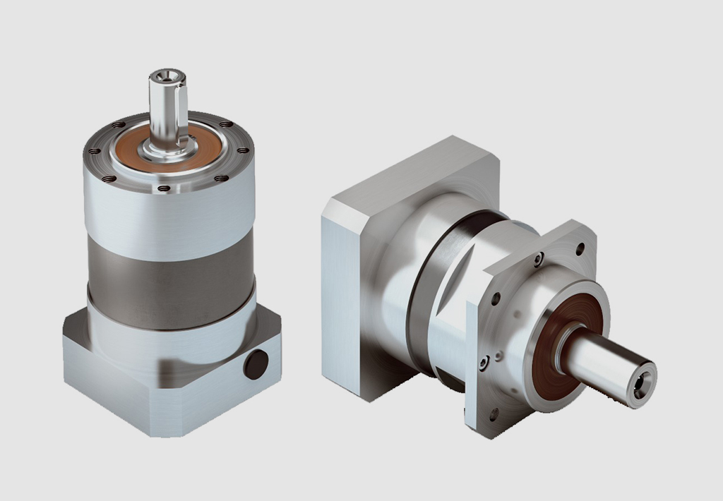
Precision of Gear Tooth Profiles in Servo Gearboxes
Manufacturers take several measures to ensure the precision of gear tooth profiles in servo gearboxes:
1. Advanced Manufacturing Processes: Manufacturers use advanced machining techniques such as CNC (Computer Numerical Control) machining and grinding to achieve high precision in gear tooth profiles. These processes allow for accurate shaping and finishing of the gear teeth.
2. Quality Materials: High-quality materials with consistent properties are selected for manufacturing gear components. This ensures uniformity in the gear teeth and minimizes variations that could affect precision.
3. Tight Tolerances: Manufacturers set tight tolerances for gear tooth dimensions, including pitch, profile, and helix angle. This helps to maintain precise engagement between gear teeth, reducing backlash and ensuring accurate motion control.
4. Quality Control: Rigorous quality control measures are implemented at various stages of the manufacturing process. This includes inspections, measurements, and tests to verify that gear tooth profiles meet the required specifications.
5. CNC Gear Inspection: Manufacturers use CNC gear inspection machines that can measure and analyze gear tooth profiles with high accuracy. These machines generate detailed reports about tooth geometry, ensuring compliance with design specifications.
6. Computer-Aided Design (CAD) and Simulation: Manufacturers use CAD software to design gear tooth profiles with precision. Simulation tools analyze how different factors, such as material properties and manufacturing processes, affect the final gear tooth shape.
7. Profile Corrections: In some cases, manufacturers apply profile corrections to optimize gear tooth profiles. These corrections compensate for any deviations that may occur during the manufacturing process.
8. Feedback from Application: Manufacturers often collaborate closely with end-users to gather feedback on the performance of gearboxes in real-world applications. This feedback helps refine the manufacturing process and improve the precision of gear tooth profiles.
The combination of advanced manufacturing techniques, strict quality control, and continuous improvement processes ensures that servo gearboxes maintain the precision required for accurate motion control in various applications.
Benefits of Using a Servo Gearbox for Precise Motion Control
Servo gearboxes offer several advantages when it comes to achieving precise motion control in various applications:
1. Accuracy: Servo gearboxes provide exceptional accuracy in speed and position control, making them suitable for applications that require tight tolerances and precise movements.
2. Low Backlash: These gearboxes are designed to minimize backlash, which is essential for eliminating lost motion and ensuring accurate positioning.
3. High Torque Density: Servo gearboxes offer a high torque-to-size ratio, allowing them to handle significant loads while maintaining a compact footprint.
4. Dynamic Performance: They excel in dynamic performance, enabling rapid changes in speed and direction with minimal overshoot or settling time.
5. Responsiveness: Servo gearboxes respond quickly to control signals, making them ideal for applications that require rapid adjustments and changes in direction.
6. Smooth Operation: These gearboxes provide smooth and precise movement, critical for applications like robotics, where jerky or uneven motion can lead to inaccuracies or damage.
7. Reduces Maintenance: The accuracy and durability of servo gearboxes can reduce wear and tear on other components, leading to lower maintenance requirements.
8. Improved Efficiency: Servo gearboxes offer high efficiency in power transmission, contributing to energy savings and minimizing heat generation.
9. Customization: They can be tailored to specific application needs, including factors like reduction ratios, mounting options, and feedback compatibility.
10. Versatility: Servo gearboxes find application in various industries, including robotics, CNC machining, medical equipment, and automation.
Overall, the benefits of using a servo gearbox for precise motion control make them an essential component in applications that demand accuracy, responsiveness, and reliable performance.
editor by CX 2023-09-23
China Custom Helical Worm Gear Motor 3 Phase Worm Gear Speed Reducer Gear Box for Cement Mixer planetary gearbox
Product Description
Detailed Photos
Features of S series reducer
The same model can be equipped with motors of various powers. It is easy to realize the combination and connection between various models.
The transmission efficiency is high, and the single reducer efficiency is up to 96%. three
The transmission ratio is subdivided and the range is wide. The combined model can form a large transmission ratio and low output speed.
The installation forms are various, and can be installed with any foot, B5 flange or B4 flange. The foot mounting reducer has 2 machined foot mounting planes.
Helical gear and worm gear combination, compact structure, large reduction ratio.
Installation mode: foot installation, hollow shaft installation, flange installation, torque arm installation, small flange installation.
Input mode: motor direct connection, motor belt connection or input shaft, connection flange input.
Average efficiency: reduction ratio 7.5-69.39 is 77%; 70.43-288 is 62%; The S/R combination is 57%.
S57 SF57 SA57 SAF57 S series helical worm gear box speed reducer 0.18kw 0.25kw 0.37kw 0.55kw 0.75kw 1.1kw 1.5kw 2.2kw 3kw, max. permissible torque up to 300Nm, transmission ratios from 10.78 to 196.21. Mounting mode: foot mounted, flange mounted, short flange mounted, torque arm mounted. Output shaft: CHINAMFG shaft, hollow shaft (with key, with shrink disc and with involute spline).
Product Parameters
Company Profile
Certifications
Packaging & Shipping
FAQ
| Hardness: | Hardened Tooth Surface |
|---|---|
| Installation: | 90 Degree |
| Layout: | Expansion |
| Gear Shape: | Bevel Gear |
| Step: | Single-Step |
| Type: | Gear Reducer |
| Samples: |
US$ 100/Piece
1 Piece(Min.Order) | |
|---|

How to Install and Align a Worm Reducer Properly
Proper installation and alignment of a worm reducer are crucial for ensuring optimal performance and longevity. Follow these steps to install and align a worm reducer:
- Preparation: Gather all the necessary tools, equipment, and safety gear before starting the installation process.
- Positioning: Place the worm reducer in the desired location, ensuring that it is securely mounted to a stable surface. Use appropriate fasteners and mounting brackets as needed.
- Shaft Alignment: Check the alignment of the input and output shafts. Use precision measurement tools to ensure that the shafts are parallel and in line with each other.
- Base Plate Alignment: Align the base plate of the reducer with the foundation or mounting surface. Ensure that the base plate is level and properly aligned before securing it in place.
- Bolt Tightening: Gradually and evenly tighten the mounting bolts to the manufacturer's specifications. This helps ensure proper contact between the reducer and the mounting surface.
- Check for Clearance: Verify that there is enough clearance for any rotating components or parts that may move during operation. Avoid any interference that could cause damage or performance issues.
- Lubrication: Apply the recommended lubricant to the worm reducer according to the manufacturer's guidelines. Proper lubrication is essential for smooth operation and reducing friction.
- Alignment Testing: After installation, run the worm reducer briefly without a load to check for any unusual noises, vibrations, or misalignment issues.
- Load Testing: Gradually introduce the intended load to the worm reducer and monitor its performance. Ensure that the reducer operates smoothly and efficiently under the load conditions.
It's important to refer to the manufacturer's installation guidelines and specifications for your specific worm reducer model. Proper installation and alignment will contribute to the gearbox's reliability, efficiency, and overall functionality.

Worm Gearbox vs. Helical Gearbox: A Comparison
Worm gearboxes and helical gearboxes are two popular types of gear systems, each with its own set of advantages and disadvantages. Let's compare them:
| Aspect | Worm Gearbox | Helical Gearbox |
| Efficiency | Lower efficiency due to sliding friction between the worm and worm wheel. | Higher efficiency due to rolling contact between helical gear teeth. |
| Torque Transmission | Excellent torque transmission and high reduction ratios achievable in a single stage. | Good torque transmission, but may require multiple stages for high reduction ratios. |
| Noise and Vibration | Generally higher noise and vibration levels due to sliding action. | Lower noise and vibration levels due to smoother rolling contact. |
| Backlash | Higher inherent backlash due to the design. | Lower backlash due to meshing of helical teeth. |
| Efficiency at Higher Speeds | Less suitable for high-speed applications due to efficiency loss. | More suitable for high-speed applications due to higher efficiency. |
| Overload Protection | Natural self-locking feature provides some overload protection. | May not have the same level of inherent overload protection. |
| Applications | Commonly used for applications requiring high reduction ratios, such as conveyor systems and heavy-duty machinery. | Widely used in various applications including automotive transmissions, industrial machinery, and more. |
Both worm and helical gearboxes have their place in engineering, and the choice between them depends on the specific requirements of the application. Worm gearboxes are preferred for applications with high reduction ratios, while helical gearboxes are chosen for their higher efficiency and smoother operation.

What is a Worm Gearbox and How Does It Work?
A worm gearbox, also known as a worm gear reducer, is a mechanical device used to transmit rotational motion and torque between non-parallel shafts. It consists of a worm screw and a worm wheel, both of which have helical teeth. The worm screw resembles a threaded cylinder, while the worm wheel is a gear with teeth that mesh with the worm screw.
The working principle of a worm gearbox involves the interaction between the worm screw and the worm wheel. When the worm screw is rotated, its helical teeth engage with the teeth of the worm wheel. As the worm screw rotates, it translates the rotational motion into a perpendicular motion, causing the worm wheel to rotate. This perpendicular motion allows the worm gearbox to achieve a high gear reduction ratio, making it suitable for applications that require significant speed reduction.
One of the key features of a worm gearbox is its ability to provide a high gear reduction ratio in a compact design. However, due to the sliding nature of the meshing teeth, worm gearboxes may exhibit higher friction and lower efficiency compared to other types of gearboxes. Therefore, they are often used in applications where efficiency is not the primary concern but where high torque and speed reduction are essential, such as conveyor systems, elevators, automotive steering systems, and certain industrial machinery.
editor by CX 2023-09-15
China OEM Custom CNC Shaft 304 CNC Machined Long Shaft Motor Drive Shaft
Product Description
Product Description
|
Company Profile
HangZhou Xihu (West Lake) Dis. Machinery Manufacture Co., Ltd., located in HangZhou, "China's ancient copper capital", is a "national high-tech enterprise". At the beginning of its establishment, the company adhering to the "to provide clients with high quality products, to provide timely service" concept, adhere to the "everything for the customer, make customer excellent supplier" for the mission.
Certifications
Q: Where is your company located ?
A: HangZhou ZheJiang .
Q: How could l get a sample?
A: Before we received the first order, please afford the sample cost and express fee. we will return the sample cost back
to you within your first order.
Q: Sample time?
A: Existing items: within 20-60 days.
Q: Whether you could make our brand on your products?
A: Yes. We can print your Logo on both the products and the packages if you can meet our MOQ.
Q: How to guarantee the quality of your products?
A: 1) stict detection during production. 2) Strict completely inspecion on products before shipment and intact product
packaging ensured.
Q: lf my drawings are safe?
A: Yes ,we can CZPT NDA.
| Material: | Carbon Steel |
|---|---|
| Load: | Drive Shaft |
| Stiffness & Flexibility: | Stiffness / Rigid Axle |
| Journal Diameter Dimensional Accuracy: | OEM/ODM/Customized |
| Axis Shape: | Straight Shaft |
| Shaft Shape: | OEM/ODM/Customized |
| Customization: |
Available
| Customized Request |
|---|

What maintenance practices are crucial for prolonging the lifespan of drive shafts?
To prolong the lifespan of drive shafts and ensure their optimal performance, several maintenance practices are crucial. Regular maintenance helps identify and address potential issues before they escalate, reduces wear and tear, and ensures the drive shaft operates smoothly and efficiently. Here are some essential maintenance practices for prolonging the lifespan of drive shafts:
1. Regular Inspection:
Performing regular inspections is vital for detecting any signs of wear, damage, or misalignment. Inspect the drive shaft visually, looking for cracks, dents, or any signs of excessive wear on the shaft itself and its associated components such as joints, yokes, and splines. Check for any signs of lubrication leaks or contamination. Additionally, inspect the fasteners and mounting points to ensure they are secure. Early detection of any issues allows for timely repairs or replacements, preventing further damage to the drive shaft.
2. Lubrication:
Proper lubrication is essential for the smooth operation and longevity of drive shafts. Lubricate the joints, such as universal joints or constant velocity joints, as recommended by the manufacturer. Lubrication reduces friction, minimizes wear, and helps dissipate heat generated during operation. Use the appropriate lubricant specified for the specific drive shaft and application, considering factors such as temperature, load, and operating conditions. Regularly check the lubrication levels and replenish as necessary to ensure optimal performance and prevent premature failure.
3. Balancing and Alignment:
Maintaining proper balancing and alignment is crucial for the lifespan of drive shafts. Imbalances or misalignments can lead to vibrations, accelerated wear, and potential failure. If vibrations or unusual noises are detected during operation, it is important to address them promptly. Perform balancing procedures as necessary, including dynamic balancing, to ensure even weight distribution along the drive shaft. Additionally, verify that the drive shaft is correctly aligned with the engine or power source and the driven components. Misalignment can cause excessive stress on the drive shaft, leading to premature failure.
4. Protective Coatings:
Applying protective coatings can help prolong the lifespan of drive shafts, particularly in applications exposed to harsh environments or corrosive substances. Consider using coatings such as zinc plating, powder coating, or specialized corrosion-resistant coatings to enhance the drive shaft's resistance to corrosion, rust, and chemical damage. Regularly inspect the coating for any signs of degradation or damage, and reapply or repair as necessary to maintain the protective barrier.
5. Torque and Fastener Checks:
Ensure that the drive shaft's fasteners, such as bolts, nuts, or clamps, are properly torqued and secured according to the manufacturer's specifications. Loose or improperly tightened fasteners can lead to excessive vibrations, misalignment, or even detachment of the drive shaft. Periodically check and retighten the fasteners as recommended or after any maintenance or repair procedures. Additionally, monitor the torque levels during operation to ensure they remain within the specified range, as excessive torque can strain the drive shaft and lead to premature failure.
6. Environmental Protection:
Protecting the drive shaft from environmental factors can significantly extend its lifespan. In applications exposed to extreme temperatures, moisture, chemicals, or abrasive substances, take appropriate measures to shield the drive shaft. This may include using protective covers, seals, or guards to prevent contaminants from entering and causing damage. Regular cleaning of the drive shaft, especially in dirty or corrosive environments, can also help remove debris and prevent buildup that could compromise its performance and longevity.
7. Manufacturer Guidelines:
Follow the manufacturer's guidelines and recommendations for maintenance practices specific to the drive shaft model and application. The manufacturer's instructions may include specific intervals for inspections, lubrication, balancing, or other maintenance tasks. Adhering to these guidelines ensures that the drive shaft is properly maintained and serviced, maximizing its lifespan and minimizing the risk of unexpected failures.
By implementing these maintenance practices, drive shafts can operate reliably, maintain efficient power transmission, and have an extended service life, ultimately reducing downtime and ensuring optimal performance in various applications.

What safety precautions should be followed when working with drive shafts?
Working with drive shafts requires adherence to specific safety precautions to prevent accidents, injuries, and damage to equipment. Drive shafts are critical components of a vehicle or machinery's driveline system and can pose hazards if not handled properly. Here's a detailed explanation of the safety precautions that should be followed when working with drive shafts:
1. Personal Protective Equipment (PPE):
Always wear appropriate personal protective equipment when working with drive shafts. This may include safety goggles, gloves, steel-toed boots, and protective clothing. PPE helps protect against potential injuries from flying debris, sharp edges, or accidental contact with moving parts.
2. Lockout/Tagout Procedures:
Before working on a drive shaft, ensure that the power source is properly locked out and tagged out. This involves isolating the power supply, such as shutting off the engine or disconnecting the electrical power, and securing it with a lockout/tagout device. This prevents accidental engagement of the drive shaft while maintenance or repair work is being performed.
3. Vehicle or Equipment Support:
When working with drive shafts in vehicles or equipment, use proper support mechanisms to prevent unexpected movement. Securely block the vehicle's wheels or utilize support stands to prevent the vehicle from rolling or shifting during drive shaft removal or installation. This helps maintain stability and reduces the risk of accidents.
4. Proper Lifting Techniques:
When handling heavy drive shafts, use proper lifting techniques to prevent strain or injuries. Lift with the help of a suitable lifting device, such as a hoist or jack, and ensure that the load is evenly distributed and securely attached. Avoid lifting heavy drive shafts manually or with improper lifting equipment, as this can lead to accidents and injuries.
5. Inspection and Maintenance:
Prior to working on a drive shaft, thoroughly inspect it for any signs of damage, wear, or misalignment. If any abnormalities are detected, consult a qualified technician or engineer before proceeding. Regular maintenance is also essential to ensure the drive shaft is in good working condition. Follow the manufacturer's recommended maintenance schedule and procedures to minimize the risk of failures or malfunctions.
6. Proper Tools and Equipment:
Use appropriate tools and equipment specifically designed for working with drive shafts. Improper tools or makeshift solutions can lead to accidents or damage to the drive shaft. Ensure that tools are in good condition, properly sized, and suitable for the task at hand. Follow the manufacturer's instructions and guidelines when using specialized tools or equipment.
7. Controlled Release of Stored Energy:
Some drive shafts, particularly those with torsional dampers or other energy-storing components, can store energy even when the power source is disconnected. Exercise caution when working on such drive shafts and ensure that the stored energy is safely released before disassembly or removal.
8. Training and Expertise:
Work on drive shafts should only be performed by individuals with the necessary training, knowledge, and expertise. If you are not familiar with drive shafts or lack the required skills, seek assistance from qualified technicians or professionals. Improper handling or installation of drive shafts can lead to accidents, damage, or compromised performance.
9. Follow Manufacturer's Guidelines:
Always follow the manufacturer's guidelines, instructions, and warnings specific to the drive shaft you are working with. These guidelines provide important information regarding installation, maintenance, and safety considerations. Deviating from the manufacturer's recommendations may result in unsafe conditions or void warranty coverage.
10. Disposal of Old or Damaged Drive Shafts:
Dispose of old or damaged drive shafts in accordance with local regulations and environmental guidelines. Improper disposal can have negative environmental impacts and may violate legal requirements. Consult with local waste management authorities or recycling centers to ensure appropriate disposal methods are followed.
By following these safety precautions, individuals can minimize the risks associated with working with drive shafts and promote a safe working environment. It is crucial to prioritize personal safety, use proper equipment and techniques, and seek professional help when needed to ensure the proper handling and maintenance of drive shafts.
What is a drive shaft and how does it function in vehicles and machinery?
A drive shaft, also known as a propeller shaft or prop shaft, is a mechanical component that plays a critical role in transmitting rotational power from the engine to the wheels or other driven components in vehicles and machinery. It is commonly used in various types of vehicles, including cars, trucks, motorcycles, and agricultural or industrial machinery. Here's a detailed explanation of what a drive shaft is and how it functions:
1. Definition and Construction: A drive shaft is a cylindrical metal tube that connects the engine or power source to the wheels or driven components. It is typically made of steel or aluminum and consists of one or more tubular sections with universal joints (U-joints) at each end. These U-joints allow for angular movement and compensation of misalignment between the engine/transmission and the driven wheels or components.
2. Power Transmission: The primary function of a drive shaft is to transmit rotational power from the engine or power source to the wheels or driven components. In vehicles, the drive shaft connects the transmission or gearbox output shaft to the differential, which then transfers power to the wheels. In machinery, the drive shaft transfers power from the engine or motor to various driven components such as pumps, generators, or other mechanical systems.
3. Torque and Speed: The drive shaft is responsible for transmitting both torque and rotational speed. Torque is the rotational force generated by the engine or power source, while rotational speed is the number of revolutions per minute (RPM). The drive shaft must be capable of transmitting the required torque without excessive twisting or bending and maintaining the desired rotational speed for efficient operation of the driven components.
4. Flexible Coupling: The U-joints on the drive shaft provide a flexible coupling that allows for angular movement and compensation of misalignment between the engine/transmission and the driven wheels or components. As the suspension system of a vehicle moves or the machinery operates on uneven terrain, the drive shaft can adjust its length and angle to accommodate these movements, ensuring smooth power transmission and preventing damage to the drivetrain components.
5. Length and Balance: The length of the drive shaft is determined by the distance between the engine or power source and the driven wheels or components. It should be appropriately sized to ensure proper power transmission and avoid excessive vibrations or bending. Additionally, the drive shaft is carefully balanced to minimize vibrations and rotational imbalances, which can cause discomfort, reduce efficiency, and lead to premature wear of drivetrain components.
6. Safety Considerations: Drive shafts in vehicles and machinery require proper safety measures. In vehicles, drive shafts are often enclosed within a protective tube or housing to prevent contact with moving parts and reduce the risk of injury in the event of a malfunction or failure. Additionally, safety shields or guards are commonly installed around exposed drive shafts in machinery to protect operators from potential hazards associated with rotating components.
7. Maintenance and Inspection: Regular maintenance and inspection of drive shafts are essential to ensure their proper functioning and longevity. This includes checking for signs of wear, damage, or excessive play in the U-joints, inspecting the drive shaft for any cracks or deformations, and lubricating the U-joints as recommended by the manufacturer. Proper maintenance helps prevent failures, ensures optimal performance, and prolongs the service life of the drive shaft.
In summary, a drive shaft is a mechanical component that transmits rotational power from the engine or power source to the wheels or driven components in vehicles and machinery. It functions by providing a rigid connection between the engine/transmission and the driven wheels or components, while also allowing for angular movement and compensation of misalignment through the use of U-joints. The drive shaft plays a crucial role in power transmission, torque and speed delivery, flexible coupling, length and balance considerations, safety, and maintenance requirements. Its proper functioning is essential for the smooth and efficient operation of vehicles and machinery.


editor by CX 2023-09-15