Product Description
| Product name | Precision Planetary Reducer |
| Model No. | AB42-AB220 |
| Layout form | Planetary structure |
| Speed ratio | 3-512 |
| Output torque | 20-1500N.M |
| Power | 50W~30KW |
| Input speed | 0~4000RPM |
| Output speed | 0~1300RPM |
| Output type | Shaft type |
| Installation | Flange mounting |
Product Description
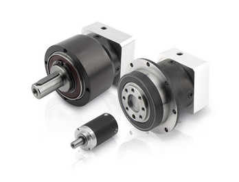
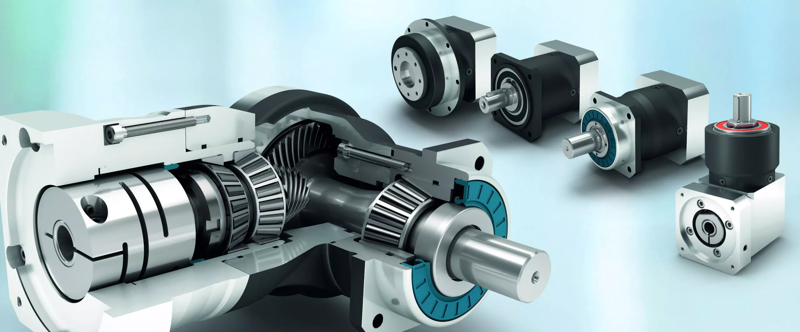
Precision planetary gear reducer is another name for planetary gear reducer in the industry. Its main transmission structure is planetary gear, sun gear and inner gear ring.
Compared with other gear reducers, precision planetary gear reducers have the characteristics of high rigidity, high precision (single stage can achieve less than 1 point), high transmission efficiency (single stage can achieve 97% - 98%), high torque/volume ratio, lifelong maintenance-free, etc. Most of them are installed on stepper motor and servo motor to reduce speed, improve torque and match inertia.
Company Profile
/* March 10, 2571 17:59:20 */!function(){function s(e,r){var a,o={};try{e&&e.split(",").forEach(function(e,t){e&&(a=e.match(/(.*?):(.*)$/))&&1
| Hardness: | Hardened Tooth Surface |
|---|---|
| Installation: | Vertical Type |
| Layout: | Coaxial |
| Gear Shape: | Planetary |
| Step: | Single-Step |
| Type: | Gear Reducer |
| Samples: |
US$ 100/Piece
1 Piece(Min.Order) | |
|---|

High-Speed Applications and Accuracy in Servo Gearboxes
Servo gearboxes can indeed be used in high-speed applications without compromising accuracy, thanks to their design features:
1. Precision Engineering: Servo gearboxes are engineered with high precision, which allows them to maintain accurate motion control even at high speeds.
2. Reduced Backlash: Many servo gearbox designs incorporate mechanisms to minimize backlash, which is the lost motion between input and output. This feature enhances accuracy even in high-speed scenarios.
3. Advanced Bearings: High-quality bearings used in servo gearboxes reduce friction and contribute to maintaining accuracy and efficiency at high speeds.
4. Rigid Construction: The rigid construction of servo gearboxes minimizes flexing or deformation under high-speed loads, ensuring that the intended motion is accurately transmitted.
5. Dynamic Balancing: Some servo gearboxes are dynamically balanced to minimize vibrations that could affect accuracy during high-speed operation.
6. Lubrication: Proper lubrication practices play a vital role. The right lubricant minimizes friction, heat, and wear, ensuring accuracy even at high speeds.
7. Feedback Systems: High-speed applications often use feedback systems, such as encoders, to constantly monitor and adjust the positioning. This further enhances accuracy.
8. Advanced Control Algorithms: The combination of accurate gearboxes and advanced control algorithms ensures precise motion profiles even at high speeds.
Overall, servo gearboxes are designed to excel in accuracy, precision, and efficiency, making them suitable for high-speed applications where maintaining accuracy is crucial.
Disadvantages and Limitations of Using Servo Gear Systems
Servo gear systems offer numerous benefits for precise motion control, but they also come with certain disadvantages and limitations:
1. Cost: Servo gear systems can be more expensive than traditional gearbox solutions. The combination of high-precision components, advanced electronics, and closed-loop control mechanisms can result in higher upfront costs.
2. Complexity: Servo gear systems are complex, requiring expertise in programming, tuning, and integrating the components. Setting up and fine-tuning the system can be time-consuming, especially for applications with intricate motion profiles.
3. Maintenance: The complex nature of servo gear systems can lead to increased maintenance requirements. Regular maintenance, including calibration and monitoring of sensors, is essential to ensure optimal performance and accuracy.
4. Sensitivity to Environmental Factors: Servo systems can be sensitive to environmental conditions such as temperature, humidity, and vibration. Extreme variations in these factors can impact the system's performance and accuracy.
5. Power Consumption: Servo systems can consume more power compared to other motion control solutions. This is due to the continuous monitoring, feedback processing, and control algorithms that are essential for precise motion control.
6. Size and Weight: In some cases, servo gear systems can be larger and heavier than traditional gearbox setups, which can impact the overall design and space requirements of the machinery or equipment.
7. Overkill for Some Applications: Not all applications require the high precision and capabilities offered by servo gear systems. In simpler applications, the added complexity and cost may not be justified.
8. Compatibility Challenges: Integrating servo gear systems with existing equipment or machinery can be challenging, especially if the components are not designed to work together seamlessly.
While servo gear systems provide exceptional precision and control, it's important to carefully evaluate the specific requirements of the application and consider the associated disadvantages and limitations before choosing this solution.
Industries Utilizing Servo Gearboxes
Servo gearboxes find applications in various industries where precise motion control is essential:
1. Robotics and Automation: Servo gearboxes are widely used in robotics and automation systems for accurate and dynamic movement control, enhancing the performance of industrial robots, collaborative robots (cobots), and other automated machinery.
2. Aerospace and Aviation: The aerospace industry utilizes servo gearboxes in aircraft control systems, including ailerons, elevators, and rudders, to ensure precise and responsive flight control.
3. Medical Equipment: Medical devices and equipment, such as surgical robots, diagnostic instruments, and imaging systems, rely on servo gearboxes to achieve precise and controlled movements for medical procedures and patient care.
4. Manufacturing and Assembly: Servo gearboxes are essential in manufacturing and assembly lines for tasks such as pick-and-place operations, conveyor systems, packaging machinery, and precision machining.
5. Automotive Industry: Automotive manufacturing and testing processes benefit from servo gearboxes for tasks such as vehicle assembly, quality control, and testing systems.
6. Semiconductor Manufacturing: High-precision processes in semiconductor manufacturing, including wafer handling and positioning, utilize servo gearboxes to maintain accuracy in microchip fabrication.
7. Material Handling: Servo gearboxes play a role in material handling systems, such as automated guided vehicles (AGVs), palletizers, and cranes, ensuring smooth and controlled movement of goods.
8. Entertainment and Theme Parks: Roller coasters, animatronics, and other entertainment attractions utilize servo gearboxes to create dynamic and engaging experiences for visitors.
9. Textile Industry: Servo gearboxes are used in textile machinery for processes like spinning, weaving, and knitting, enabling precise control of thread tension and fabric movement.
10. Research and Development: In research settings, servo gearboxes are employed for experimentation, testing, and prototyping of mechanical systems and prototypes.
Servo gearboxes provide the necessary precision, flexibility, and reliability required in these industries, enabling advanced motion control and enhancing the efficiency and performance of various applications.


editor by CX 2023-12-27
China OEM Aluminum Helical Gear Box best automatic gearbox
Product Description
Starshine Drive NCJ Series Helical Geared Motor
Features:
- High efficiency and energy saving: low energy, low noise, small vibration, low temperature rise, wide output speed, and high efficiency: 92%-96%.
- With wide variable range of voltage and frequency motor from 20HZ to 60HZ, and voltage from 320V to 420V.
- Modular design with strong interchangeability.
- Iron or aluminum casting house, good rigidity, high strength and excellent heat-loss.
- Advanced design: gear pair processed by carburizing and quenching heat treatment, and unique low noise gear tooth design to ensure the service life.
- Free maintenance: special lubrication to guarantee normal running for 20,000 hours without oil replacement;
- Easy replacement: can replace cycloid gearbox and upgrade product
Technical Parameters
| Type | Old Type | Output Torque | Output Shaft Dia. |
| SNR02 | NCJ02 | 130N.m | φ22 |
| SNR03 | NCJ03 | 250N.m | φ28 |
| SNR04 | NCJ04 | 500N.m | φ32 |
| SNR05 | NCJ05 | 750N.m | φ40 |
| SNRW03Y | NCJT03Y2 | 250N.m | φ35 |
| SNRL04Y | NCJF04Y2 | 450N.m | φ35 |
About Us
ZheJiang CHINAMFG Drive Co.,Ltd(Starshine) have a strong technical force with over 350 employees at present, including over 30 engineering technicians, 30 quality inspectors, covering an area of 80000 square CHINAMFG and kinds of advanced processing machines and testing equipments. We have a good foundation for the industry application development and service of high-end speed reducers & variators owning to the provincial engineering technology research center,the lab of gear speed reducers, and the base of modern R&D.
Our Team
Quality Control
Quality:Insist on Improvement,Strive for CHINAMFG With the development of equipment manufacturing indurstry,customer never satirsfy with the current quality of our products,on the contrary,wcreate the value of quality.
Quality policy:to enhance the overall level in the field of power transmission
Quality View:Continuous Improvement , pursuit of excellence
Quality Philosophy:Quality creates value
3. Incoming Quality Control
To establish the AQL acceptable level of incoming material control, to provide the material for the whole inspection, sampling, immunity. On the acceptance of qualified products to warehousing, substandard goods to take return, check, rework, rework inspection; responsible for tracking bad, to monitor the supplier to take corrective measures to prevent recurrence.
4. Process Quality Control
The manufacturing site of the first examination, inspection and final inspection, sampling according to the requirements of some projects, judging the quality change trend; found abnormal phenomenon of manufacturing, and supervise the production department to improve, eliminate the abnormal phenomenon or state.
5. FQC(Final QC)
After the manufacturing department will complete the product, stand in the customer's position on the finished product quality verification, in order to ensure the quality of customer expectations and needs.
6. OQC(Outgoing QC)
After the product sample inspection to determine the qualified, allowing storage, but when the finished product from the warehouse before the formal delivery of the goods, there is a check, this is called the shipment inspection.Check content:In the warehouse storage and transfer status to confirm, while confirming the delivery of the product is a product inspection to determine the qualified products.
7. Certificate: all of our products pass ISO, CE certificate.
Packing
Delivery
| Application: | Motor, Machinery, Agricultural Machinery |
|---|---|
| Function: | Speed Changing, Speed Reduction |
| Layout: | Coaxial |
| Hardness: | Hardened Tooth Surface |
| Installation: | Horizontal Type |
| Step: | Double-Step |
| Customization: |
Available
| Customized Request |
|---|
Lubrication Practices for Maintaining Servo Gearbox Performance
Proper lubrication is essential for maintaining the performance and longevity of servo gearboxes:
1. High-Quality Lubricants: Selecting the right lubricant is crucial. High-quality lubricants with the appropriate viscosity and additives are chosen based on factors like load, speed, and operating conditions.
2. Lubricant Compatibility: Ensure that the chosen lubricant is compatible with the materials used in the gearbox construction, including seals, bearings, and gears.
3. Regular Lubrication Checks: Regularly inspect the lubricant level and condition. Monitor for signs of contamination, degradation, or overheating.
4. Proper Lubricant Amount: Avoid overfilling or underfilling the gearbox. Follow manufacturer guidelines for the correct lubricant amount to ensure optimal performance.
5. Scheduled Lubrication Intervals: Establish a maintenance schedule for lubricant replacement based on operating hours, usage intensity, and environmental conditions.
6. Lubricant Contamination Prevention: Keep the gearbox environment clean and free from contaminants like dust, dirt, and moisture to prevent lubricant contamination.
7. Lubricant Temperature: Monitor and control the operating temperature of the gearbox to prevent lubricant breakdown and ensure proper viscosity.
8. Re-Greasing: In some cases, re-greasing may be necessary due to lubricant aging or displacement. Follow manufacturer recommendations for re-greasing intervals.
9. Seal Inspection: Check the seals regularly for wear and damage. Damaged seals can lead to lubricant leakage and contamination.
10. Expert Consultation: If unsure about lubricant selection or maintenance procedures, consult with experts or follow manufacturer recommendations.
Proper lubrication practices play a critical role in minimizing friction, reducing wear, and ensuring the efficient operation of servo gearboxes in motion control systems.

Considerations for Selecting the Right Servo Gearbox for an Application
Choosing the appropriate servo gearbox for a specific application requires careful evaluation of several key factors:
1. Torque and Speed Requirements: Determine the required torque and speed characteristics of the application, ensuring that the chosen servo gearbox can provide the necessary output.
2. Gear Ratio: Calculate the ideal gear ratio based on the desired motion profile, acceleration, and deceleration requirements.
3. Mounting and Integration: Consider the available space and mechanical layout of the machinery to choose a servo gearbox with the appropriate mounting configuration.
4. Motor Compatibility: Ensure that the servo gearbox is compatible with the specific type and size of motor being used for the application.
5. Precision and Accuracy: Evaluate the level of precision required for the application's motion control. Choose a servo gearbox that can deliver the necessary accuracy and repeatability.
6. Load Distribution: Analyze how the load will be distributed among the gears to prevent excessive wear and ensure optimal performance.
7. Backlash and Compliance: Consider the application's tolerance for backlash and compliance. Choose a servo gearbox with low backlash if precise positioning is essential.
8. Environmental Conditions: Factor in the environmental conditions of the application, such as temperature, humidity, and exposure to contaminants. Choose a servo gearbox with suitable sealing and protection.
9. Lubrication: Determine the lubrication requirements of the gearbox and select a model that aligns with the application's maintenance practices.
10. Overload and Shock: Consider potential overload and shock conditions the gearbox may experience. Choose a servo gearbox that can handle sudden changes in load without compromising performance.
11. Feedback Devices: If precise motion control is required, choose a servo gearbox that is compatible with the desired feedback devices, such as encoders or resolvers.
12. Efficiency: Evaluate the efficiency of the servo gearbox to ensure that it contributes to the overall energy efficiency of the system.
13. Service and Support: Select a reputable manufacturer that offers reliable technical support, documentation, and post-purchase services.
14. Budget: Balance the performance requirements of the application with the available budget to make an informed decision.
By carefully considering these factors, engineers and designers can confidently choose the right servo gearbox that meets the specific needs of their application, optimizing performance and productivity.
Industries Utilizing Servo Gearboxes
Servo gearboxes find applications in various industries where precise motion control is essential:
1. Robotics and Automation: Servo gearboxes are widely used in robotics and automation systems for accurate and dynamic movement control, enhancing the performance of industrial robots, collaborative robots (cobots), and other automated machinery.
2. Aerospace and Aviation: The aerospace industry utilizes servo gearboxes in aircraft control systems, including ailerons, elevators, and rudders, to ensure precise and responsive flight control.
3. Medical Equipment: Medical devices and equipment, such as surgical robots, diagnostic instruments, and imaging systems, rely on servo gearboxes to achieve precise and controlled movements for medical procedures and patient care.
4. Manufacturing and Assembly: Servo gearboxes are essential in manufacturing and assembly lines for tasks such as pick-and-place operations, conveyor systems, packaging machinery, and precision machining.
5. Automotive Industry: Automotive manufacturing and testing processes benefit from servo gearboxes for tasks such as vehicle assembly, quality control, and testing systems.
6. Semiconductor Manufacturing: High-precision processes in semiconductor manufacturing, including wafer handling and positioning, utilize servo gearboxes to maintain accuracy in microchip fabrication.
7. Material Handling: Servo gearboxes play a role in material handling systems, such as automated guided vehicles (AGVs), palletizers, and cranes, ensuring smooth and controlled movement of goods.
8. Entertainment and Theme Parks: Roller coasters, animatronics, and other entertainment attractions utilize servo gearboxes to create dynamic and engaging experiences for visitors.
9. Textile Industry: Servo gearboxes are used in textile machinery for processes like spinning, weaving, and knitting, enabling precise control of thread tension and fabric movement.
10. Research and Development: In research settings, servo gearboxes are employed for experimentation, testing, and prototyping of mechanical systems and prototypes.
Servo gearboxes provide the necessary precision, flexibility, and reliability required in these industries, enabling advanced motion control and enhancing the efficiency and performance of various applications.
editor by CX 2023-11-18
China manufacturer Factory price Helical spiral conical worm gear worm Gear R K S F four series hard tooth surface speed reducer gear box manufacturer
Product Description
| Model Number | S series Worm gear reducer | Structure Type | S SA SAF SAT SAZ |
| Assembly Method | 1-6 | Input power | 0.18-22W |
| Enamelled Wire: | 100% Copper Wire | Reducer body | Steel |
| Ratio | 10.27-230.48 | Brand | FOX MOTOR |
| Application: | Motor, Machinery, Agricultural Machinery, paper machine |
|---|---|
| Hardness: | Hardened Tooth Surface |
| Installation: | Horizontal or Vertical |
| Layout: | Helical gear reducer |
| Gear Shape: | Bevel Gear |
| Step: | one stage -three stage |
| Samples: |
US$ 99/Piece
1 Piece(Min.Order) | |
|---|
| Customization: |
Available
| Customized Request |
|---|

Can a Worm Gearbox Be Used in Heavy-Duty Machinery?
Yes, a worm gearbox can be used in heavy-duty machinery and is often chosen for such applications due to its inherent characteristics and advantages:
- High Torque Transmission: Worm gearboxes are known for their ability to transmit high torque loads, making them suitable for heavy-duty machinery that requires significant power transmission.
- Load Distribution: The design of worm gears provides robust load distribution and excellent contact between the worm and worm wheel teeth. This enhances their load-carrying capacity, making them capable of handling heavy loads without premature wear or failure.
- Compact Design: Worm gearboxes are compact and offer high reduction ratios in a single stage. This allows for the reduction of high input speeds to lower output speeds, often required in heavy-duty machinery.
- Overload Protection: Worm gears have a natural self-locking feature, which means the gear cannot be easily back-driven by external forces. This feature provides inherent overload protection, preventing damage to the gearbox and machinery in cases of sudden load spikes.
- Smooth Operation: Worm gearboxes offer smooth and steady operation, which is crucial for heavy-duty machinery where precision and controlled movement are essential.
However, when considering the use of a worm gearbox in heavy-duty applications, it's important to ensure proper engineering and sizing. The design should account for factors such as load, speed, duty cycle, lubrication, and temperature to ensure optimal performance and longevity.
Overall, worm gearboxes are well-suited for heavy-duty machinery across various industries, including mining, construction, manufacturing, and more.

Worm Gearbox vs. Helical Gearbox: A Comparison
Worm gearboxes and helical gearboxes are two popular types of gear systems, each with its own set of advantages and disadvantages. Let's compare them:
| Aspect | Worm Gearbox | Helical Gearbox |
| Efficiency | Lower efficiency due to sliding friction between the worm and worm wheel. | Higher efficiency due to rolling contact between helical gear teeth. |
| Torque Transmission | Excellent torque transmission and high reduction ratios achievable in a single stage. | Good torque transmission, but may require multiple stages for high reduction ratios. |
| Noise and Vibration | Generally higher noise and vibration levels due to sliding action. | Lower noise and vibration levels due to smoother rolling contact. |
| Backlash | Higher inherent backlash due to the design. | Lower backlash due to meshing of helical teeth. |
| Efficiency at Higher Speeds | Less suitable for high-speed applications due to efficiency loss. | More suitable for high-speed applications due to higher efficiency. |
| Overload Protection | Natural self-locking feature provides some overload protection. | May not have the same level of inherent overload protection. |
| Applications | Commonly used for applications requiring high reduction ratios, such as conveyor systems and heavy-duty machinery. | Widely used in various applications including automotive transmissions, industrial machinery, and more. |
Both worm and helical gearboxes have their place in engineering, and the choice between them depends on the specific requirements of the application. Worm gearboxes are preferred for applications with high reduction ratios, while helical gearboxes are chosen for their higher efficiency and smoother operation.

What Industries Commonly Use Worm Reducers?
Worm reducers are versatile mechanical components that find applications in various industries due to their unique advantages and capabilities. Some of the industries that commonly use worm reducers include:
- Material Handling: Worm reducers are widely used in material handling equipment such as conveyors, bucket elevators, and cranes to control movement and manage heavy loads.
- Automotive: They are utilized in automotive manufacturing processes, assembly lines, and vehicle positioning systems.
- Food and Beverage: Worm reducers are used in food processing and packaging machinery where hygiene and cleanliness are crucial.
- Agriculture: Agricultural equipment like irrigation systems and tractors use worm reducers for controlling rotational motion.
- Mining and Construction: Heavy-duty applications in mining equipment, excavators, and construction machinery benefit from the torque multiplication provided by worm reducers.
- Energy: Wind turbines and solar tracking systems use worm reducers to convert low-speed, high-torque motion into rotational energy.
- Textile: Textile machinery employs worm reducers for controlling speed and tension in weaving and spinning operations.
- Packaging: Packaging equipment relies on worm reducers for precise movement and positioning of packaging materials.
- Medical: Medical devices and equipment often utilize worm reducers for their accuracy and controlled motion.
- Printing: Printing machines use worm reducers to regulate paper feed and ensure consistent printing quality.
Worm reducers' ability to provide high torque output, compact design, and self-locking characteristics makes them suitable for applications requiring reliable and controlled motion across various industries.
editor by CX 2023-09-15
China Custom Helical Worm Gear Motor 3 Phase Worm Gear Speed Reducer Gear Box for Cement Mixer planetary gearbox
Product Description
Detailed Photos
Features of S series reducer
The same model can be equipped with motors of various powers. It is easy to realize the combination and connection between various models.
The transmission efficiency is high, and the single reducer efficiency is up to 96%. three
The transmission ratio is subdivided and the range is wide. The combined model can form a large transmission ratio and low output speed.
The installation forms are various, and can be installed with any foot, B5 flange or B4 flange. The foot mounting reducer has 2 machined foot mounting planes.
Helical gear and worm gear combination, compact structure, large reduction ratio.
Installation mode: foot installation, hollow shaft installation, flange installation, torque arm installation, small flange installation.
Input mode: motor direct connection, motor belt connection or input shaft, connection flange input.
Average efficiency: reduction ratio 7.5-69.39 is 77%; 70.43-288 is 62%; The S/R combination is 57%.
S57 SF57 SA57 SAF57 S series helical worm gear box speed reducer 0.18kw 0.25kw 0.37kw 0.55kw 0.75kw 1.1kw 1.5kw 2.2kw 3kw, max. permissible torque up to 300Nm, transmission ratios from 10.78 to 196.21. Mounting mode: foot mounted, flange mounted, short flange mounted, torque arm mounted. Output shaft: CHINAMFG shaft, hollow shaft (with key, with shrink disc and with involute spline).
Product Parameters
Company Profile
Certifications
Packaging & Shipping
FAQ
| Hardness: | Hardened Tooth Surface |
|---|---|
| Installation: | 90 Degree |
| Layout: | Expansion |
| Gear Shape: | Bevel Gear |
| Step: | Single-Step |
| Type: | Gear Reducer |
| Samples: |
US$ 100/Piece
1 Piece(Min.Order) | |
|---|

How to Install and Align a Worm Reducer Properly
Proper installation and alignment of a worm reducer are crucial for ensuring optimal performance and longevity. Follow these steps to install and align a worm reducer:
- Preparation: Gather all the necessary tools, equipment, and safety gear before starting the installation process.
- Positioning: Place the worm reducer in the desired location, ensuring that it is securely mounted to a stable surface. Use appropriate fasteners and mounting brackets as needed.
- Shaft Alignment: Check the alignment of the input and output shafts. Use precision measurement tools to ensure that the shafts are parallel and in line with each other.
- Base Plate Alignment: Align the base plate of the reducer with the foundation or mounting surface. Ensure that the base plate is level and properly aligned before securing it in place.
- Bolt Tightening: Gradually and evenly tighten the mounting bolts to the manufacturer's specifications. This helps ensure proper contact between the reducer and the mounting surface.
- Check for Clearance: Verify that there is enough clearance for any rotating components or parts that may move during operation. Avoid any interference that could cause damage or performance issues.
- Lubrication: Apply the recommended lubricant to the worm reducer according to the manufacturer's guidelines. Proper lubrication is essential for smooth operation and reducing friction.
- Alignment Testing: After installation, run the worm reducer briefly without a load to check for any unusual noises, vibrations, or misalignment issues.
- Load Testing: Gradually introduce the intended load to the worm reducer and monitor its performance. Ensure that the reducer operates smoothly and efficiently under the load conditions.
It's important to refer to the manufacturer's installation guidelines and specifications for your specific worm reducer model. Proper installation and alignment will contribute to the gearbox's reliability, efficiency, and overall functionality.
Worm Gearbox vs. Helical Gearbox: A Comparison
Worm gearboxes and helical gearboxes are two popular types of gear systems, each with its own set of advantages and disadvantages. Let's compare them:
| Aspect | Worm Gearbox | Helical Gearbox |
| Efficiency | Lower efficiency due to sliding friction between the worm and worm wheel. | Higher efficiency due to rolling contact between helical gear teeth. |
| Torque Transmission | Excellent torque transmission and high reduction ratios achievable in a single stage. | Good torque transmission, but may require multiple stages for high reduction ratios. |
| Noise and Vibration | Generally higher noise and vibration levels due to sliding action. | Lower noise and vibration levels due to smoother rolling contact. |
| Backlash | Higher inherent backlash due to the design. | Lower backlash due to meshing of helical teeth. |
| Efficiency at Higher Speeds | Less suitable for high-speed applications due to efficiency loss. | More suitable for high-speed applications due to higher efficiency. |
| Overload Protection | Natural self-locking feature provides some overload protection. | May not have the same level of inherent overload protection. |
| Applications | Commonly used for applications requiring high reduction ratios, such as conveyor systems and heavy-duty machinery. | Widely used in various applications including automotive transmissions, industrial machinery, and more. |
Both worm and helical gearboxes have their place in engineering, and the choice between them depends on the specific requirements of the application. Worm gearboxes are preferred for applications with high reduction ratios, while helical gearboxes are chosen for their higher efficiency and smoother operation.

What is a Worm Gearbox and How Does It Work?
A worm gearbox, also known as a worm gear reducer, is a mechanical device used to transmit rotational motion and torque between non-parallel shafts. It consists of a worm screw and a worm wheel, both of which have helical teeth. The worm screw resembles a threaded cylinder, while the worm wheel is a gear with teeth that mesh with the worm screw.
The working principle of a worm gearbox involves the interaction between the worm screw and the worm wheel. When the worm screw is rotated, its helical teeth engage with the teeth of the worm wheel. As the worm screw rotates, it translates the rotational motion into a perpendicular motion, causing the worm wheel to rotate. This perpendicular motion allows the worm gearbox to achieve a high gear reduction ratio, making it suitable for applications that require significant speed reduction.
One of the key features of a worm gearbox is its ability to provide a high gear reduction ratio in a compact design. However, due to the sliding nature of the meshing teeth, worm gearboxes may exhibit higher friction and lower efficiency compared to other types of gearboxes. Therefore, they are often used in applications where efficiency is not the primary concern but where high torque and speed reduction are essential, such as conveyor systems, elevators, automotive steering systems, and certain industrial machinery.
editor by CX 2023-09-15
China Best Sales S Series Helical Worm Variable Speed Gear Box with Motor cycloidal gearbox
Product Description
S Series Helical Worm Variable Speed Gear Box with Motor
1. Product Characteristics
S series helical worm gearbox adopts the helical worm gears to make its structure more reasonable. S series not only has higher transmission efficency and loading capability than those single-stage worm wheel transmission, but also smaller volume and appearance. Moreover, S series worm gearbox has higher transmission ratio, and can be combined with various gearboxes and speed variators to meet the different requirements.
2. Technical Data
| Rated Power | 0.18~22KW |
| Output Speed | 0.16~147r/min |
| Output Torque | 90~4000N.m |
| Mounted Form | Foot-mounted, flange mounted, shaft-mounted, torque arm mounted |
| Housing | Aluminum and Casting Iron |
3. Structure
S series gearbox are available in the following designs:
(1) SY Foot mounted helical worm gearbox with CHINAMFG shaft
(2) SAY Helical worm gearbox with hollow shaft
(3) SAZY Small flange mounted helical worm gearbox with hollow shaft
(4) SA (S,SF,SAF,SAZ)Y Assemble users' motor or special motor, flange is required
(5) SFY Flange mounted helical worm gearbox with CHINAMFG shaft
(6) SAFY Flange mounted helical worm gearbox with hollow shaft
(7) SATY Torque arm mounted helical worm gearbox with hollow shaft
(8) S (SF,SA,SAF,SAZ) S Shaft input helical worm gearbox
(9) SA (S,SF,SAF,SAZ)RY Combined helical worm gearbox
(10) SA (S,SF,SAF,SAZ)SR Shaft input combined helical worm gearbox
4. Detailed parameters
| Size | 38 | 48 | 58 | 68 | 78 | 88 | 98 |
| Structure | S SA SF SAF SAT SAZ | ||||||
| Input Power(KW) | 0.18-0.75 | 0.18-1.5 | 0.18-3 | 0.25-5.5 | 0.55-7.5 | 0.75-15 | 1.5-22 |
| Ratio | 10.27-152 | 11.46-244.74 | 10.78-196.21 | 11.55-227.20 | 9.96-241.09 | 11.83-222 | 12.75-230.48 |
| Maximum torque(N.m) | 90 | 170 | 295 | 520 | 1270 | 2280 | 4000 |
5.Product Pictures:
6.Our company :
AOKMAN was founded in 1982, which has more than 36 years in R & D and manufacturing of gearboxes, gears, shaft, motor and spare parts.
We can offer the proper solution for uncountable applications. Our products are widely used in the ranges of metallurgical, steel, mining, pulp and paper, sugar and alcohol market and various other types of machines with a strong presence in the international market.
AOKMAN has become a reliable supplier, able to supply high quality gearboxes.With 36 years experience, we assure you the utmost reliability and security for both product and services.
7.Customer visiting:
8.Our Services:
| Pre-sale services | 1. Select equipment model. |
| 2.Design and manufacture products according to clients' special requirement. | |
| 3.Train technical personal for clients | |
| Services during selling | 1.Pre-check and accept products ahead of delivery. |
| 2. Help clients to draft solving plans. | |
| After-sale services | 1.Assist clients to prepare for the first construction scheme. |
| 2. Train the first-line operators. | |
| 3.Take initiative to eliminate the trouble rapidly. | |
| 4. Provide technical exchanging. |
9.FAQ:
1.Q:What kinds of gearbox can you produce for us?
A:Main products of our company: UDL series speed variator,RV series worm gear reducer, ATA series shaft mounted gearbox, X,B series gear reducer,
P series planetary gearbox and R, S, K, and F series helical-tooth reducer, more
than 1 hundred models and thousands of specifications
2.Q:Can you make as per custom drawing?
A: Yes, we offer customized service for customers.
3.Q:What is your terms of payment ?
A: 30% Advance payment by T/T after signing the contract.70% before delivery
4.Q:What is your MOQ?
A: 1 Set
If you have any demand for our products please feel free to contact me.
| Application: | Machinery, Reducer |
|---|---|
| Function: | Change Drive Torque, Speed Changing, Speed Reduction |
| Layout: | Right Angle |
| Hardness: | Hardened |
| Type: | Worm and Wormwheel |
| Material: | Cast Iron |
| Customization: |
Available
| Customized Request |
|---|
How to Install and Align a Worm Reducer Properly
Proper installation and alignment of a worm reducer are crucial for ensuring optimal performance and longevity. Follow these steps to install and align a worm reducer:
- Preparation: Gather all the necessary tools, equipment, and safety gear before starting the installation process.
- Positioning: Place the worm reducer in the desired location, ensuring that it is securely mounted to a stable surface. Use appropriate fasteners and mounting brackets as needed.
- Shaft Alignment: Check the alignment of the input and output shafts. Use precision measurement tools to ensure that the shafts are parallel and in line with each other.
- Base Plate Alignment: Align the base plate of the reducer with the foundation or mounting surface. Ensure that the base plate is level and properly aligned before securing it in place.
- Bolt Tightening: Gradually and evenly tighten the mounting bolts to the manufacturer's specifications. This helps ensure proper contact between the reducer and the mounting surface.
- Check for Clearance: Verify that there is enough clearance for any rotating components or parts that may move during operation. Avoid any interference that could cause damage or performance issues.
- Lubrication: Apply the recommended lubricant to the worm reducer according to the manufacturer's guidelines. Proper lubrication is essential for smooth operation and reducing friction.
- Alignment Testing: After installation, run the worm reducer briefly without a load to check for any unusual noises, vibrations, or misalignment issues.
- Load Testing: Gradually introduce the intended load to the worm reducer and monitor its performance. Ensure that the reducer operates smoothly and efficiently under the load conditions.
It's important to refer to the manufacturer's installation guidelines and specifications for your specific worm reducer model. Proper installation and alignment will contribute to the gearbox's reliability, efficiency, and overall functionality.

Worm Gearboxes in Conveyor Systems: Benefits and Considerations
Worm gearboxes play a crucial role in conveyor systems, offering several benefits and considerations for their effective integration:
- Space Efficiency: Worm gearboxes have a compact design, making them suitable for applications with limited space, such as conveyor systems.
- High Reduction Ratios: Worm gearboxes can achieve high reduction ratios in a single stage, allowing for slower conveyor speeds without sacrificing torque.
- Self-Locking: Worm gearboxes have inherent self-locking properties, preventing the conveyor from moving when the motor is not actively driving it.
- Directional Control: Worm gearboxes facilitate directional control, enabling the conveyor to move forward or reverse as needed.
- Low Noise: Worm gearboxes often produce lower noise levels compared to other gearbox types, contributing to quieter conveyor operation.
However, there are also considerations to keep in mind when using worm gearboxes in conveyor systems:
- Efficiency: Worm gearboxes may have lower mechanical efficiency compared to some other gearbox types, leading to energy losses.
- Heat Generation: Worm gearboxes can generate more heat due to sliding contact between the worm and gear, necessitating proper cooling mechanisms.
- Lubrication: Proper lubrication is critical to prevent wear and ensure efficient operation. Regular maintenance is required to monitor lubrication levels.
- Load and Speed: Worm gearboxes are well-suited for applications with high torque and low to moderate speed requirements. They may not be optimal for high-speed conveyors.
Before integrating a worm gearbox into a conveyor system, it's important to carefully consider the specific requirements of the application, including load, speed, space constraints, and efficiency needs. Consulting with gearbox experts and manufacturers can help ensure the right choice for the conveyor's performance and longevity.
Advantages of Using a Worm Reducer in Mechanical Systems
Worm reducers offer several advantages that make them suitable for various mechanical systems:
- High Gear Reduction Ratio: Worm gearboxes provide significant speed reduction, making them ideal for applications that require a high gear reduction ratio without the need for multiple gears.
- Compact Design: Worm reducers have a compact and space-saving design, allowing them to be used in applications with limited space.
- Self-Locking: Worm gearboxes exhibit self-locking properties, which means that the worm screw can prevent the worm wheel from reversing its motion. This is beneficial for applications where the gearbox needs to hold a load in place without external braking mechanisms.
- Smooth and Quiet Operation: Worm gearboxes operate with a sliding motion between the teeth, resulting in smoother and quieter operation compared to some other types of gearboxes.
- High Torque Transmission: Worm gearboxes can transmit high torque levels, making them suitable for applications that require powerful torque output.
- Heat Dissipation: The sliding action between the worm screw and the worm wheel contributes to heat dissipation, which can be advantageous in applications that generate heat during operation.
- Stable Performance: Worm reducers offer stable and reliable performance, making them suitable for continuous operation in various industrial and mechanical systems.
Despite these advantages, it's important to note that worm gearboxes also have limitations, such as lower efficiency compared to other gear types due to the sliding motion and potential for higher heat generation. Therefore, selecting the appropriate type of gearbox depends on the specific requirements and constraints of the application.
editor by CX 2023-09-15
China high quality R F K S Series Parallel Shaft Inline Gear Box Speed Reducer Reducer Worm Bevel Helical Geared Motor Gearbox gearbox definition
Product Description
Product Advantages
| Size | R37 | R57 | R77 | R87 | R107 |
| Ratio | 3.41-134.82 | 4.39-782 | 5.31-1430 | 5.3-2873 | 6.66-7583 |
| Power | 0.12KW-3KW | 0.12KW-7.5KW | 0.12KW-11KW | 0.12KW-18.5KW | 0.12KW-18.5KW |
| Output torque | 30-205N.M | 40-400N.M | 50-795N.M | 50-1610N.M | 80-4870N.M |
| Output speed(RPM) | 0.1-821RPM | 0.1-660RPM | 0.1-795RPM | 0.1-276RPM | 0.1-220RPM |
R series reducer has the characteristics of small volume and large torque transmission. It is designed and manufactured on the basis of modular combination system. There are many motor combinations,installation forms and structural schemes. R series reducer adopts the modular design principle of unit structure, with high transmission efficiency, low energy consumption and superior performance.
Product Description
Detailed Photos
Our Advantages
| Application: | Motor, Motorcycle, Machinery, Agricultural Machine, Lift |
|---|---|
| Hardness: | Hardened Tooth Surface |
| Installation: | Horizontal Type |
| Layout: | Expansion, Parallel |
| Gear Shape: | Bevel Gear |
| Step: | Single-Step |
| Samples: |
US$ 500/Piece
1 Piece(Min.Order) | |
|---|
What are the Noise Levels Associated with Worm Gearboxes?
The noise levels associated with worm gearboxes can vary depending on several factors, including the design, quality, operating conditions, and maintenance of the gearbox. Here are some key points to consider:
- Design and Quality: Well-designed and high-quality worm gearboxes tend to produce lower noise levels. Factors such as gear tooth profile, precision manufacturing, and proper alignment can contribute to reduced noise.
- Gear Engagement: The way the worm and worm wheel engage and mesh with each other can impact noise levels. Proper tooth contact and alignment can help minimize noise during operation.
- Lubrication: Inadequate or improper lubrication can lead to increased friction and wear, resulting in higher noise levels. Using the recommended lubricant and maintaining proper lubrication levels are important for noise reduction.
- Operating Conditions: Operating the gearbox within its specified load and speed limits can help prevent excessive noise generation. Overloading or operating at high speeds beyond the gearbox's capabilities can lead to increased noise.
- Backlash: Excessive backlash or play between the gear teeth can lead to impact noise as the teeth engage. Proper backlash adjustment can help mitigate this issue.
- Maintenance: Regular maintenance, including gear inspection, lubrication checks, and addressing any wear or damage, can help keep noise levels in check.
It's important to note that while worm gearboxes can produce some noise due to the nature of gear meshing, proper design, maintenance, and operation can significantly reduce noise levels. If noise is a concern for your application, consulting with gearbox manufacturers and experts can provide insights into selecting the right gearbox type and implementing measures to minimize noise.

Energy Efficiency of a Worm Gearbox: What to Expect
The energy efficiency of a worm gearbox is an important factor to consider when evaluating its performance. Here's what you can expect in terms of energy efficiency:
- Typical Efficiency Range: Worm gearboxes are known for their compact size and high gear reduction capabilities, but they can exhibit lower energy efficiency compared to other types of gearboxes. The efficiency of a worm gearbox typically falls in the range of 50% to 90%, depending on various factors such as design, manufacturing quality, lubrication, and load conditions.
- Inherent Losses: Worm gearboxes inherently involve sliding contact between the worm and worm wheel. This sliding contact generates friction, leading to energy losses in the form of heat. The sliding action also contributes to lower efficiency when compared to gearboxes with rolling contact.
- Helical-Worm Design: Some manufacturers offer helical-worm gearbox designs that combine elements of helical and worm gearing. These designs aim to improve efficiency by incorporating helical gears in the reduction stage, which can lead to higher efficiency compared to traditional worm gearboxes.
- Lubrication: Proper lubrication plays a significant role in minimizing friction and improving energy efficiency. Using high-quality lubricants and ensuring the gearbox is adequately lubricated can help reduce losses due to friction.
- Application Considerations: While worm gearboxes might have lower energy efficiency compared to other types of gearboxes, they still offer advantages in terms of compactness, high torque transmission, and simplicity. Therefore, the decision to use a worm gearbox should consider the specific requirements of the application, including the trade-off between energy efficiency and other performance factors.
When selecting a worm gearbox, it's essential to consider the trade-offs between energy efficiency, torque transmission, gearbox size, and the specific needs of the application. Regular maintenance, proper lubrication, and selecting a well-designed gearbox can contribute to achieving the best possible energy efficiency within the limitations of worm gearbox technology.

Lubrication Requirements for a Worm Gearbox
Lubrication is crucial for maintaining the performance and longevity of a worm gearbox. Here are the key considerations for lubricating a worm gearbox:
- Type of Lubricant: Use a high-quality, high-viscosity lubricant specifically designed for worm gearboxes. Worm gearboxes require lubricants with additives that provide proper lubrication and prevent wear.
- Lubrication Interval: Follow the manufacturer's recommendations for lubrication intervals. Regularly check the gearbox's temperature and oil condition to determine the optimal frequency of lubrication.
- Oil Level: Maintain the proper oil level to ensure effective lubrication. Too little oil can lead to insufficient lubrication, while too much oil can cause overheating and foaming.
- Lubrication Points: Identify all the lubrication points on the gearbox, including the worm and wheel gear surfaces. Apply the lubricant evenly to ensure complete coverage.
- Temperature: Consider the operating temperature of the gearbox. Some lubricants have temperature limits, and extreme temperatures can affect lubricant viscosity and performance.
- Cleanliness: Keep the gearbox and the surrounding area clean to prevent contaminants from entering the lubricant. Use proper filtration and seals to maintain a clean environment.
- Monitoring: Regularly monitor the gearbox's temperature, noise level, and vibration to detect any signs of inadequate lubrication or other issues.
Proper lubrication will reduce friction, wear, and heat generation, ensuring smooth and efficient operation of the worm gearbox. Always refer to the manufacturer's guidelines for lubrication specifications and intervals.
editor by CX 2023-09-15
China Professional Mechanical Self Locked SA Series Saf57 Helical Worm Gear Box for Elevator with high quality
Product Description
Detailed Photos
Features of S series reducer
The same model can be equipped with motors of various powers. It is easy to realize the combination and connection between various models.
The transmission efficiency is high, and the single reducer efficiency is up to 96%. three
The transmission ratio is subdivided and the range is wide. The combined model can form a large transmission ratio and low output speed.
The installation forms are various, and can be installed with any foot, B5 flange or B4 flange. The foot mounting reducer has 2 machined foot mounting planes.
Helical gear and worm gear combination, compact structure, large reduction ratio.
Installation mode: foot installation, hollow shaft installation, flange installation, torque arm installation, small flange installation.
Input mode: motor direct connection, motor belt connection or input shaft, connection flange input.
Average efficiency: reduction ratio 7.5-69.39 is 77%; 70.43-288 is 62%; The S/R combination is 57%.
S57 SF57 SA57 SAF57 S series helical worm gear box speed reducer 0.18kw 0.25kw 0.37kw 0.55kw 0.75kw 1.1kw 1.5kw 2.2kw 3kw, max. permissible torque up to 300Nm, transmission ratios from 10.78 to 196.21. Mounting mode: foot mounted, flange mounted, short flange mounted, torque arm mounted. Output shaft: CHINAMFG shaft, hollow shaft (with key, with shrink disc and with involute spline).
Product Parameters
Company Profile
Certifications
Packaging & Shipping
FAQ
| Hardness: | Hardened Tooth Surface |
|---|---|
| Installation: | 90 Degree |
| Layout: | Expansion |
| Gear Shape: | Bevel Gear |
| Step: | Single-Step |
| Type: | Gear Reducer |
| Samples: |
US$ 100/Piece
1 Piece(Min.Order) | |
|---|

Is it Possible to Reverse the Direction of a Worm Gearbox?
Yes, it is possible to reverse the direction of a worm gearbox by changing the orientation of either the input or output shaft. However, reversing the direction of a worm gearbox can have some implications that need to be considered:
- Efficiency: Reversing the direction of a worm gearbox can potentially affect its efficiency. Worm gearboxes are typically more efficient in one direction of rotation due to the design of the worm and worm wheel.
- Backlash: Reversing the direction of rotation might lead to increased backlash or play in the gearbox, which can impact precision and smooth operation.
- Lubrication: Depending on the gearbox's design, reversing the direction could affect lubrication distribution and lead to uneven wear on the gear teeth.
- Load: Reversing the direction might also impact the gearbox's load-carrying capacity, especially if it's designed for predominantly one-way operation.
- Noise and Vibration: Direction reversal can sometimes result in increased noise and vibration due to changes in gear engagement and meshing behavior.
If you need to reverse the direction of a worm gearbox, it's advisable to consult the gearbox manufacturer's guidelines and recommendations. They can provide insights into whether the specific gearbox model is suitable for reversible operation and any precautions or adjustments needed to ensure proper functioning.

How to Calculate the Efficiency of a Worm Gearbox
Calculating the efficiency of a worm gearbox involves determining the ratio of output power to input power. Efficiency is a measure of how well the gearbox converts input power into useful output power without losses. Here's how to calculate it:
- Step 1: Measure Input Power: Measure the input power (Pin) using a power meter or other suitable measuring equipment.
- Step 2: Measure Output Power: Measure the output power (Pout) that the gearbox is delivering to the load.
- Step 3: Calculate Efficiency: Calculate the efficiency (η) using the formula: Efficiency (η) = (Output Power / Input Power) * 100%
For example, if the input power is 1000 watts and the output power is 850 watts, the efficiency would be (850 / 1000) * 100% = 85%.
It's important to note that efficiencies can vary based on factors such as gear design, lubrication, wear, and load conditions. The calculated efficiency provides insight into how effectively the gearbox is converting power, but it's always a good practice to refer to manufacturer specifications for gearbox efficiency ratings.
Types of Worm Gear Configurations and Their Uses
Worm gear configurations vary based on the arrangement of the worm and the gear it engages with. Here are common types and their applications:
- Single Enveloping Worm Gear: This configuration offers high torque transmission and efficiency. It's used in heavy-duty applications like mining equipment and industrial machinery.
- Double Enveloping Worm Gear: With increased contact area, this type provides higher load capacity and improved efficiency. It's used in aerospace applications, robotics, and precision machinery.
- Non-Throated Worm Gear: This type has a cylindrical worm without a throat. It's suitable for applications requiring precise motion control, such as CNC machines and robotics.
- Throated Worm Gear: Featuring a throat in the worm, this configuration offers smooth engagement and higher load capacity. It's used in conveyors, elevators, and automotive applications.
- Non-Modular Worm Gear: In this design, the worm and gear are a matched set, resulting in better meshing and efficiency. It's utilized in various industries where customization is essential.
- Modular Worm Gear: This type allows interchangeability of worm and gear components, providing flexibility in design and maintenance. It's commonly used in conveyors, mixers, and material handling systems.
Selecting the appropriate worm gear configuration depends on factors such as load capacity, efficiency, precision, and application requirements. Consulting gearbox experts can help determine the best configuration for your specific needs.
editor by CX 2023-09-14
China high quality CZPT Drive Cast Iron ZY Series Helical Gear Box Speed Parallel Shaft Reduction Gearbox for Mine Winch with high quality
Warranty: 1 a long time, 1 Year
Applicable Industries: Creating Materials Stores, Foodstuff & Beverage Manufacturing unit, Development works , Strength & Mining
Gearing Arrangement: Helical
Output Torque: Seek advice from
Enter Pace: 1500,one thousand,750r/min
Output Speed: Dependent on Ratio
Ratio: 1.25~500
Colour: Customer’s Quest
Housing substance: Forged Iron
Gear content: 20CrMnTi Alloy Steel
Mount Situation: Horizontal Mounted
Enter Type: Solitary or Double Keyed Solid Shaft Input
Output Form: One or Double Keyed Sound Shaft Output
Certification: ISO9001
Software: CNC Tools
Packaging Particulars: Wooden Instances
Port: ZheJiang /HangZhou
Gearbox Description AOKMAN Drive Cast Iron ZY Series Helical Equipment Box Pace Parallel Shaft Reduction Gearbox for Mine Winch Components:1. Housing: Solid Iron or Steel Plate Welding2. Gear Established: Hardened Helical Gear Pairs, Carburizing, Quenching, Grinding, Gear Hardness HRC54-623. Enter Configurations:One or Double Keyed Strong Shaft Enter
four. Output Configurations:
Single or Double Keyed Sound Shaft Output
five. Main Options: BackstopForced Lubrication Oil PumpCooling Enthusiast, Cooling Coils
Designs:ZDY Collection, ZLY Sequence, ZSY Collection, ZFY Sequence
Functions:1. Optional welding metal plate equipment box2. Large high quality alloy metal helical gears, carburizing, quenching, grinding, big load capacity3. Optimized layout, interchangeable spare parts4. Substantial performance, high dependability, lengthy support lifestyle, reduced noise5. Output shaft rotation route: clockwise, counterclockwise or bidirectional6. A variety of shaft configurations: single or double enter and output shaft in 1 aspect or 2 sides7. Optional backstop and lengthening output shafts
Gearbox Parameters
ZY Sequence
Models
Ratio
ZDY (1 Phase)
ZDY80, guide transmission gearbox housing for CZPT PS125 ZDY100, ZDY125, ZDY160, ZDY200, ZDY250, ZDY280, ZDY315, ZDY355, ZDY400, ZDY450, ZDY500, ZDY560
1.25~6.3
ZLY (2 Stage)
ZLY112, ZLY125, ZLY140, ZLY160, ZLY180, ZLY200, ZLY224, ZLY250, ZLY280, ZLY315, ZLY355, ZLY400, ZLY450, V-Belt Pulley SPZ SPA SPB SPC V Groove Pulley Forged Iron Taper lock Bore V Belt Pulleys ZLY500, ZLY560, ZLY630, ZLY710
6.3~20
ZSY (3 Stage)
ZSY160, ZSY180, ZSY200, ZSY224, ZSY250, ZSY280, ZSY315, ZSY355, ZSY400, ZSY450, ZSY500, ZSY560, ZSY630, ZSY710
22.4~a hundred
ZFY (4 Phase)
ZFY180, ZFY200, ZFY225, ZFY250, ZFY280, ZFY320, ZFY360, ZFY400, China rapidly supply time 60mm Gap output planetary reducer gearbox for nema24 stepper motor HLTNC ZFY450, ZFY500, ZFY560, ZFY630, ZFY710
100~500
Gearbox Software Buyer Browsing Packing & Shipping and delivery Our Business 1. Much more than 35 several years experience in R&D and manufacturing, export gear motors & industrial gearboxes.2. Standardization of the gearbox series3. Sturdy design and style ability for big power & customized gearboxes.4. Large high quality gearboxes and verified solutions company.5. Rigorous quality handle method, stable top quality.6. Significantly less than 2% of the high quality problems.7. Modular design, brief supply time.8. Rapid response & skilled services
AOKMAN was founded in 1982, which has far more than 36 many years in R & D and production of gearboxes, gears, shaft, motor and spare areas.We can supply the correct remedy for uncountable apps. Our items are extensively utilized in the ranges of metallurgical, metal, mining, pulp and paper, sugar and alcohol market and a variety of other sorts of machines with a powerful presence in the worldwide market place.AOKMAN has grow to be a reputable supplier, Equipment Box Aluminium RV Series Pace Reducer,YNMRV Collection Worm Gearbox CZPT to source high high quality gearboxes.With 36 a long time expertise, we assure you the utmost dependability and security for the two item and services.
Associated Gearboxes Make contact with
Driveshaft framework and vibrations associated with it
The structure of the drive shaft is crucial to its effectiveness and trustworthiness. Travel shafts normally have claw couplings, rag joints and common joints. Other drive shafts have prismatic or splined joints. Discover about the distinct sorts of travel shafts and how they function. If you want to know the vibrations linked with them, read through on. But 1st, let us determine what a driveshaft is.
transmission shaft
As the demand on our vehicles proceeds to boost, so does the demand from customers on our travel techniques. Higher CO2 emission specifications and stricter emission specifications boost the stress on the generate method whilst enhancing comfort and shortening the turning radius. These and other damaging effects can area substantial tension and put on on factors, which can lead to driveshaft failure and increase car basic safety dangers. Consequently, the travel shaft should be inspected and replaced regularly.
Dependent on your model, you may possibly only want to change one driveshaft. Nonetheless, the price to substitute the two driveshafts ranges from $650 to $1850. Additionally, you might incur labor costs ranging from $one hundred forty to $250. The labor value will depend on your automobile product and its drivetrain sort. In common, nonetheless, the expense of replacing a driveshaft ranges from $470 to $1850.
Regionally, the automotive driveshaft market can be divided into four major marketplaces: North The united states, Europe, Asia Pacific, and Rest of the Entire world. North America is anticipated to dominate the market place, even though Europe and Asia Pacific are expected to develop the fastest. Moreover, the marketplace is predicted to expand at the maximum fee in the foreseeable future, driven by economic expansion in the Asia Pacific location. Furthermore, most of the autos sold globally are developed in these locations.
The most crucial function of the driveshaft is to transfer the electrical power of the motor to helpful function. Travel shafts are also acknowledged as propeller shafts and cardan shafts. In a motor vehicle, a propshaft transfers torque from the engine, transmission, and differential to the entrance or rear wheels, or equally. Thanks to the complexity of driveshaft assemblies, they are vital to motor vehicle basic safety. In addition to transmitting torque from the motor, they need to also compensate for deflection, angular modifications and size adjustments.
kind
Distinct kinds of generate shafts contain helical shafts, equipment shafts, worm shafts, planetary shafts and synchronous shafts. Radial protruding pins on the head offer a rotationally safe connection. At the very least one particular bearing has a groove extending alongside its circumferential size that permits the pin to move by way of the bearing. There can also be two flanges on each and every finish of the shaft. Dependent on the application, the shaft can be mounted in the most practical location to purpose.
Propeller shafts are usually made of higher-top quality steel with high distinct strength and modulus. Nevertheless, they can also be produced from innovative composite materials this sort of as carbon fiber, Kevlar and fiberglass. An additional kind of propeller shaft is produced of thermoplastic polyamide, which is rigid and has a substantial strength-to-fat ratio. The two push shafts and screw shafts are used to travel cars, ships and motorcycles.
Sliding and tubular yokes are frequent elements of travel shafts. By design and style, their angles need to be equal or intersect to supply the right angle of procedure. Except if the doing work angles are equal, the shaft vibrates 2 times for every revolution, triggering torsional vibrations. The greatest way to avoid this is to make confident the two yokes are correctly aligned. Crucially, these factors have the very same working angle to guarantee easy power circulation.
The kind of travel shaft may differ according to the variety of motor. Some are geared, whilst other individuals are non-geared. In some circumstances, the drive shaft is fixed and the motor can rotate and steer. Alternatively, a adaptable shaft can be utilized to manage the pace and course of the travel. In some apps the place linear electricity transmission is not attainable, adaptable shafts are a valuable choice. For instance, flexible shafts can be utilized in transportable gadgets.
place up
The building of the push shaft has several advantages in excess of bare metal. A shaft that is adaptable in a number of instructions is less difficult to sustain than a shaft that is rigid in other instructions. The shaft body and coupling flange can be manufactured of different resources, and the flange can be produced of a different substance than the principal shaft entire body. For example, the coupling flange can be created of metal. The primary shaft body is if possible flared on at minimum one particular stop, and the at least 1 coupling flange consists of a initial usually frustoconical projection extending into the flared conclude of the primary shaft entire body.
The standard stiffness of fiber-based shafts is accomplished by the orientation of parallel fibers together the length of the shaft. Nonetheless, the bending stiffness of this shaft is reduced due to the alter in fiber orientation. Given that the fibers proceed to travel in the exact same course from the very first finish to the 2nd stop, the reinforcement that boosts the torsional stiffness of the shaft is not impacted. In distinction, a fiber-primarily based shaft is also versatile due to the fact it makes use of ribs that are approximately 90 levels from the centerline of the shaft.
In addition to the helical ribs, the travel shaft one hundred could also have reinforcing elements. These reinforcing components sustain the structural integrity of the shaft. These reinforcing factors are called helical ribs. They have ribs on the two the outer and interior surfaces. This is to stop shaft breakage. These aspects can also be formed to be versatile sufficient to accommodate some of the forces created by the drive. Shafts can be made utilizing these methods and manufactured into worm-like travel shafts.
vibration
The most frequent trigger of generate shaft vibration is incorrect set up. There are 5 common kinds of driveshaft vibration, each and every related to installation parameters. To avoid this from occurring, you ought to understand what leads to these vibrations and how to fix them. The most common varieties of vibration are listed under. This write-up describes some widespread travel shaft vibration options. It might also be advantageous to take into account the tips of a skilled vibration technician for push shaft vibration management.
If you happen to be not certain if the difficulty is the driveshaft or the engine, try out turning on the stereo. Thicker carpet kits can also mask vibrations. Nevertheless, you need to contact an professional as shortly as feasible. If vibration persists following vibration-associated repairs, the driveshaft requirements to be replaced. If the driveshaft is still under guarantee, you can restore it yourself.
CV joints are the most typical lead to of 3rd-buy driveshaft vibration. If they are binding or fall short, they need to be changed. Alternatively, your CV joints might just be misaligned. If it is free, you can check the CV connector. One more widespread result in of drive shaft vibration is incorrect assembly. Improper alignment of the yokes on each finishes of the shaft can result in them to vibrate.
Incorrect trim height can also lead to driveshaft vibration. Right trim height is needed to prevent travel shaft wobble. No matter whether your motor vehicle is new or outdated, you can perform some simple fixes to decrease problems. A single of these solutions includes balancing the travel shaft. Initial, use the hose clamps to attach the weights to it. Up coming, connect an ounce of excess weight to it and spin it. By carrying out this, you decrease the frequency of vibration.
cost
The global driveshaft market is predicted to exceed (xxx) million USD by 2028, increasing at a compound annual progress price (CAGR) of XX%. Its soaring development can be attributed to many elements, including growing urbanization and R&D investments by major market place gamers. The report also contains an in-depth analysis of key market place developments and their influence on the industry. Moreover, the report gives a complete regional investigation of the Driveshaft Market place.
The value of replacing the push shaft depends on the sort of fix essential and the lead to of the failure. Standard restore fees assortment from $300 to $750. Rear-wheel generate vehicles usually cost far more. But entrance-wheel drive automobiles value considerably less than four-wheel drive vehicles. You could also select to try out fixing the driveshaft your self. Nonetheless, it is important to do your study and make positive you have the necessary tools and tools to complete the work appropriately.
The report also addresses the competitive landscape of the Push Shafts marketplace. It involves graphical representations, thorough data, administration policies, and governance parts. Additionally, it consists of a thorough price investigation. Moreover, the report offers sights on the COVID-19 industry and foreseeable future trends. The report also offers worthwhile data to support you decide how to compete in your business. When you acquire a report like this, you are including believability to your operate.
A quality driveshaft can boost your recreation by ensuring distance from the tee and enhancing responsiveness. The new materials in the shaft construction is lighter, stronger and much more responsive than at any time before, so it is getting to be a crucial component of the driver. And there are a assortment of alternatives to match any spending budget. The major issue to think about when purchasing a shaft is its quality. Even so, it is critical to notice that quality doesn't appear cheap and you ought to usually select an axle based on what your budget can deal with.

