Product Description
Product Description
NMRV series worm gear reducer
1. Aluminum alloy housing, small size, light weight.
2. High transmission efficiency, low noise.
3.Smooth ruuning, high output torque and long service life.
4. Multiple connection structure and installation.
| TYPE | Worm Gear Speed Reducer / Worm Gearbox |
| NMRV MODEL | NMRV25, NMRV30, NMRV40, NMRV50, NMRV63, NMRV75, NMRV90, NMRV110, NMRV130, NMRV150 |
| NRV MODEL | NRV25, NRV30, NRV40, NRV50, NRV63, NRV75, NRV90, NRV110, NRV130, NRV150 |
| POWER | 0.12kw-15kw |
| RATIO | 1/7.5,1/10,1/15,1/20,1/15,1/30,1/40,1/50,1/60,1/80,1/100 |
| COLOR | Blue(RAL5571), Silver grey (RAL9571), or on request |
| MATERIAL | Housing/Flange:Aluminum Alloy |
| Worm Gear:Copper 9-4&nodular iron | |
| Worm:20CrMn Ti with carburizing and quenching, surface harness is 56-62HRC | |
| Shaft:chromium steel-45# | |
| IEC FLANGE | IEC standard flange 56B14, 63B14, 63B5, 63B5, 71B14,80B14 AND SO ON |
| LUBRICANT | Synthetic & Mineral |
Detailed Photos
|
NMRV Model&marker |
|||
|
NMRV-063-30-VS-F1(FA)-AS-80B5-0.75KW-B3 |
|||
|
NMRV |
Means hole-input with flange |
||
|
NRV |
Means shaft-input without flange |
||
|
63 |
Centre-to-centre spacing of worm-gear speed reducer |
||
|
30 |
Ratio |
||
|
VS |
Double input shaft |
F1 (FA) |
Flange output |
|
AS |
Single output shaft |
AB |
Double output shaft |
|
PAM |
Fitted for motor coupling |
80B5 |
Motor mounting facility |
|
0.75kw |
Electric motor power |
B3 |
Mounting position |
NMRV NMRV+NMRV
NMRV/NRV ASSEMBLE WITH ELECTRIC MOTOR
Workshop
Manufacturing the Aluminum Housing by CNC. Lots of housings in stock.
Lots of worm gears and worm shafts in stock.
Assembling line
Packaging & Shipping
Each reducer in single carton box packed.
FAQ
Q1: Are you trading company or manufacturer ?
A: We are factory.
Q2: How long is your delivery time and shipment?
1.Sample Lead-times: 10-20 days.
2.Production Lead-times: 30-45 days after order confirmed.
Q3: What is your advantages?
1. The most competitive price and good quality.
2. Perfect technical engineers give you the best support.
3. OEM is available.
/* March 10, 2571 17:59:20 */!function(){function s(e,r){var a,o={};try{e&&e.split(",").forEach(function(e,t){e&&(a=e.match(/(.*?):(.*)$/))&&1
| Application: | Motor, Motorcycle, Machinery, Toy, Agricultural Machinery |
|---|---|
| Hardness: | Hardened Tooth Surface |
| Installation: | Vertical Type |
| Layout: | Coaxial |
| Gear Shape: | Worm Gear |
| Type: | Worm Reducer |
| Customization: |
Available
| Customized Request |
|---|
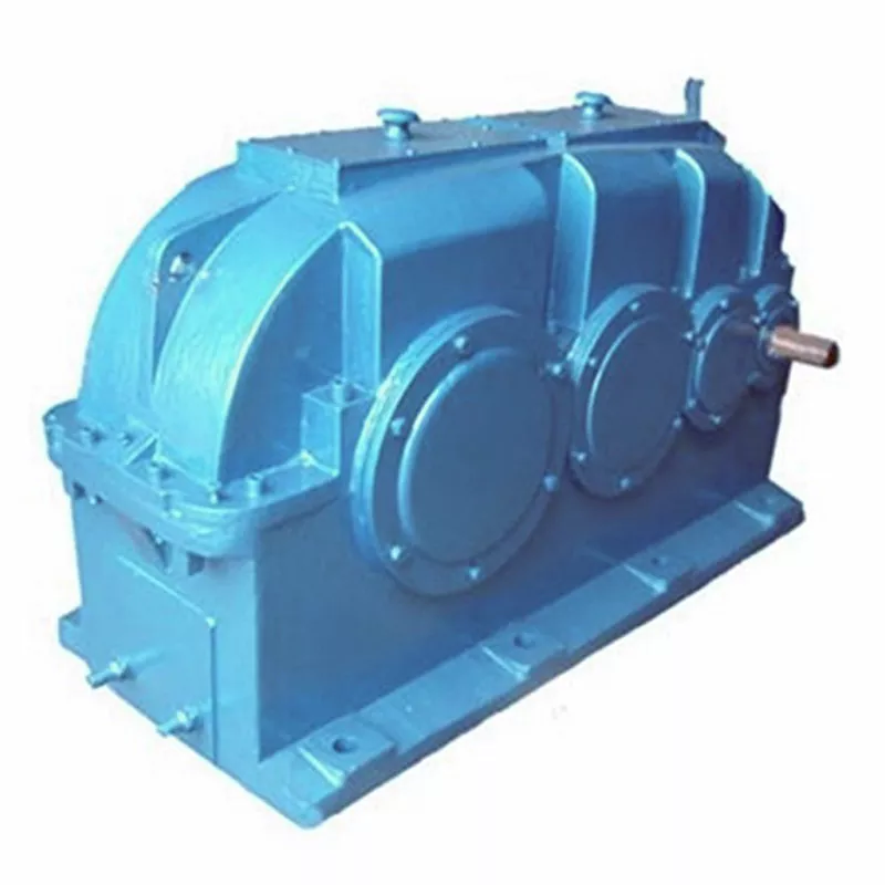
Can gear reducers be customized for specific industrial needs and requirements?
Yes, gear reducers can be customized to meet specific industrial needs and requirements. Manufacturers offer customization options to ensure that gear reducers are tailored to the unique demands of various applications:
1. Gear Ratio Selection: Gear reducers can be designed with specific gear ratios to achieve the desired speed reduction or increase, catering to the specific requirements of the machinery or equipment.
2. Shaft Configurations: Gear reducers can be configured with different shaft sizes, lengths, and orientations to fit seamlessly into existing systems or accommodate specific mounting arrangements.
3. Torque Capacity: Customized gear reducers can be designed to handle higher or lower torque loads based on the application's operational requirements.
4. Environmental Considerations: Gear reducers can be customized with special coatings, materials, or seals to withstand harsh environments, extreme temperatures, or corrosive conditions.
5. Noise and Vibration Reduction: Custom designs can incorporate features to reduce noise and dampen vibrations, enhancing the overall operation and user experience.
6. Mounting and Connection Options: Manufacturers can adapt gear reducer designs to include specific mounting interfaces or connection methods that align with the equipment's design.
7. Lubrication and Maintenance: Customized gear reducers can include features for easy maintenance, such as accessible lubrication points or monitoring systems.
8. Integration with Controls: Gear reducers can be customized to integrate seamlessly with control systems, sensors, or automation processes, enhancing system efficiency and performance.
By collaborating with manufacturers and providing detailed specifications, industries can obtain tailor-made gear reducers that address their specific operational needs and contribute to the success of their applications.
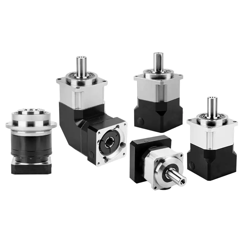
Can gear reducers be used for both speed reduction and speed increase?
Yes, gear reducers can be utilized for both speed reduction and speed increase, depending on their design and arrangement. The functionality to either decrease or increase rotational speed is achieved by altering the arrangement of gears within the gearbox.
1. Speed Reduction: In speed reduction applications, a gear reducer is designed with gears of different sizes. The input shaft connects to a larger gear, while the output shaft is connected to a smaller gear. As the input shaft rotates, the larger gear turns the smaller gear, resulting in a decrease in output speed compared to the input speed. This configuration provides higher torque output at a lower speed, making it suitable for applications that require increased force or torque.
2. Speed Increase: For speed increase, the gear arrangement is reversed. The input shaft connects to a smaller gear, while the output shaft is connected to a larger gear. As the input shaft rotates, the smaller gear drives the larger gear, resulting in an increase in output speed compared to the input speed. However, the torque output is lower than that of speed reduction configurations.
By choosing the appropriate gear ratios and arrangement, gear reducers can be customized to meet specific speed and torque requirements for various industrial applications. It's important to select the right type of gear reducer and configure it correctly to achieve the desired speed reduction or speed increase.
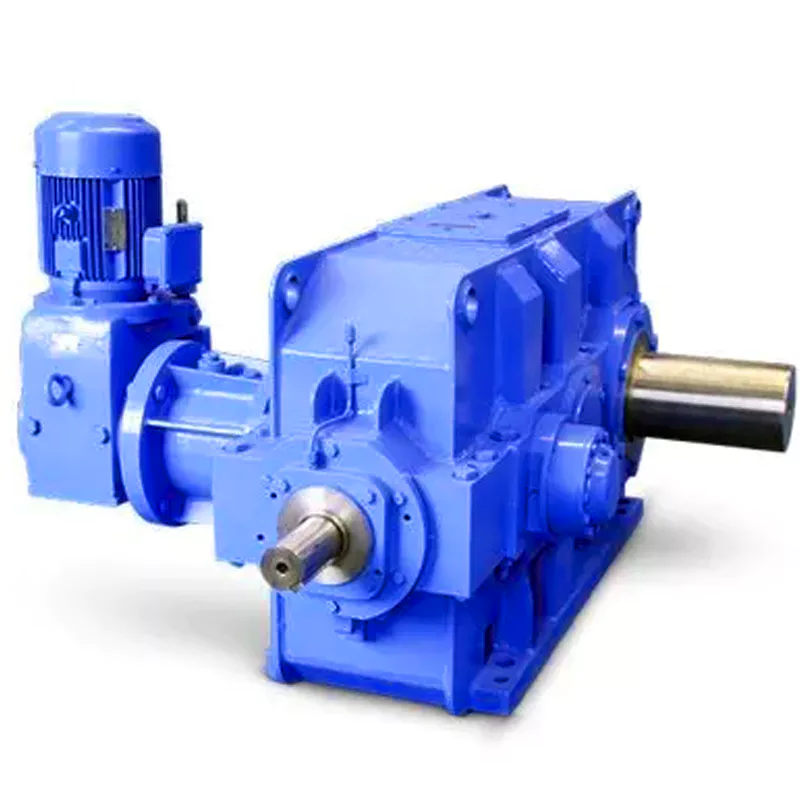
What are the benefits of using a gear reducer in industrial applications?
Gear reducers offer several benefits that make them indispensable in various industrial applications:
1. Speed Reduction: Gear reducers allow the reduction of high-speed input from motors or engines to lower, more usable output speeds for specific applications, ensuring proper equipment operation and safety.
2. Torque Increase: By leveraging the mechanical advantage of gear ratios, gear reducers can significantly increase torque output, enabling the handling of heavy loads and providing the necessary power for tasks such as lifting, conveying, and processing.
3. Precise Control: Gear reducers enable fine-tuning of rotational speed and torque, providing precise control over machinery and processes, which is crucial in industries like manufacturing, material handling, and robotics.
4. Shock Load Absorption: Gear reducers can absorb and dampen sudden shocks or changes in load, protecting both the machinery and connected components from abrupt forces that could otherwise lead to damage.
5. Versatility: With various gear types (e.g., spur, helical, worm) and designs, gear reducers can be tailored to different applications, including those requiring specific speed ratios, torque ranges, and environmental conditions.
6. Efficient Power Transmission: Gear reducers offer high mechanical efficiency, minimizing energy loss during power transmission, which is especially valuable in energy-conscious industries.
7. Compact Design: Gear reducers provide a compact solution for transmitting power and adjusting speeds, making them suitable for installations with space constraints.
8. Reliability and Longevity: Well-designed and properly maintained gear reducers can offer extended service life, contributing to reduced downtime and maintenance costs.
Overall, gear reducers enhance the performance, efficiency, and reliability of industrial equipment, making them essential components in a wide range of applications across various industries.


editor by CX 2023-12-20
China Custom Helical Worm Gear Motor 3 Phase Worm Gear Speed Reducer Gear Box for Cement Mixer planetary gearbox
Product Description
Detailed Photos
Features of S series reducer
The same model can be equipped with motors of various powers. It is easy to realize the combination and connection between various models.
The transmission efficiency is high, and the single reducer efficiency is up to 96%. three
The transmission ratio is subdivided and the range is wide. The combined model can form a large transmission ratio and low output speed.
The installation forms are various, and can be installed with any foot, B5 flange or B4 flange. The foot mounting reducer has 2 machined foot mounting planes.
Helical gear and worm gear combination, compact structure, large reduction ratio.
Installation mode: foot installation, hollow shaft installation, flange installation, torque arm installation, small flange installation.
Input mode: motor direct connection, motor belt connection or input shaft, connection flange input.
Average efficiency: reduction ratio 7.5-69.39 is 77%; 70.43-288 is 62%; The S/R combination is 57%.
S57 SF57 SA57 SAF57 S series helical worm gear box speed reducer 0.18kw 0.25kw 0.37kw 0.55kw 0.75kw 1.1kw 1.5kw 2.2kw 3kw, max. permissible torque up to 300Nm, transmission ratios from 10.78 to 196.21. Mounting mode: foot mounted, flange mounted, short flange mounted, torque arm mounted. Output shaft: CHINAMFG shaft, hollow shaft (with key, with shrink disc and with involute spline).
Product Parameters
Company Profile
Certifications
Packaging & Shipping
FAQ
| Hardness: | Hardened Tooth Surface |
|---|---|
| Installation: | 90 Degree |
| Layout: | Expansion |
| Gear Shape: | Bevel Gear |
| Step: | Single-Step |
| Type: | Gear Reducer |
| Samples: |
US$ 100/Piece
1 Piece(Min.Order) | |
|---|
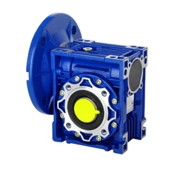
How to Install and Align a Worm Reducer Properly
Proper installation and alignment of a worm reducer are crucial for ensuring optimal performance and longevity. Follow these steps to install and align a worm reducer:
- Preparation: Gather all the necessary tools, equipment, and safety gear before starting the installation process.
- Positioning: Place the worm reducer in the desired location, ensuring that it is securely mounted to a stable surface. Use appropriate fasteners and mounting brackets as needed.
- Shaft Alignment: Check the alignment of the input and output shafts. Use precision measurement tools to ensure that the shafts are parallel and in line with each other.
- Base Plate Alignment: Align the base plate of the reducer with the foundation or mounting surface. Ensure that the base plate is level and properly aligned before securing it in place.
- Bolt Tightening: Gradually and evenly tighten the mounting bolts to the manufacturer's specifications. This helps ensure proper contact between the reducer and the mounting surface.
- Check for Clearance: Verify that there is enough clearance for any rotating components or parts that may move during operation. Avoid any interference that could cause damage or performance issues.
- Lubrication: Apply the recommended lubricant to the worm reducer according to the manufacturer's guidelines. Proper lubrication is essential for smooth operation and reducing friction.
- Alignment Testing: After installation, run the worm reducer briefly without a load to check for any unusual noises, vibrations, or misalignment issues.
- Load Testing: Gradually introduce the intended load to the worm reducer and monitor its performance. Ensure that the reducer operates smoothly and efficiently under the load conditions.
It's important to refer to the manufacturer's installation guidelines and specifications for your specific worm reducer model. Proper installation and alignment will contribute to the gearbox's reliability, efficiency, and overall functionality.
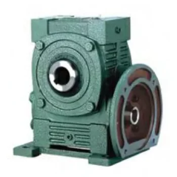
Worm Gearbox vs. Helical Gearbox: A Comparison
Worm gearboxes and helical gearboxes are two popular types of gear systems, each with its own set of advantages and disadvantages. Let's compare them:
| Aspect | Worm Gearbox | Helical Gearbox |
| Efficiency | Lower efficiency due to sliding friction between the worm and worm wheel. | Higher efficiency due to rolling contact between helical gear teeth. |
| Torque Transmission | Excellent torque transmission and high reduction ratios achievable in a single stage. | Good torque transmission, but may require multiple stages for high reduction ratios. |
| Noise and Vibration | Generally higher noise and vibration levels due to sliding action. | Lower noise and vibration levels due to smoother rolling contact. |
| Backlash | Higher inherent backlash due to the design. | Lower backlash due to meshing of helical teeth. |
| Efficiency at Higher Speeds | Less suitable for high-speed applications due to efficiency loss. | More suitable for high-speed applications due to higher efficiency. |
| Overload Protection | Natural self-locking feature provides some overload protection. | May not have the same level of inherent overload protection. |
| Applications | Commonly used for applications requiring high reduction ratios, such as conveyor systems and heavy-duty machinery. | Widely used in various applications including automotive transmissions, industrial machinery, and more. |
Both worm and helical gearboxes have their place in engineering, and the choice between them depends on the specific requirements of the application. Worm gearboxes are preferred for applications with high reduction ratios, while helical gearboxes are chosen for their higher efficiency and smoother operation.
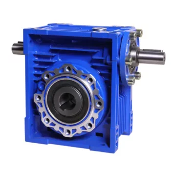
What is a Worm Gearbox and How Does It Work?
A worm gearbox, also known as a worm gear reducer, is a mechanical device used to transmit rotational motion and torque between non-parallel shafts. It consists of a worm screw and a worm wheel, both of which have helical teeth. The worm screw resembles a threaded cylinder, while the worm wheel is a gear with teeth that mesh with the worm screw.
The working principle of a worm gearbox involves the interaction between the worm screw and the worm wheel. When the worm screw is rotated, its helical teeth engage with the teeth of the worm wheel. As the worm screw rotates, it translates the rotational motion into a perpendicular motion, causing the worm wheel to rotate. This perpendicular motion allows the worm gearbox to achieve a high gear reduction ratio, making it suitable for applications that require significant speed reduction.
One of the key features of a worm gearbox is its ability to provide a high gear reduction ratio in a compact design. However, due to the sliding nature of the meshing teeth, worm gearboxes may exhibit higher friction and lower efficiency compared to other types of gearboxes. Therefore, they are often used in applications where efficiency is not the primary concern but where high torque and speed reduction are essential, such as conveyor systems, elevators, automotive steering systems, and certain industrial machinery.


editor by CX 2023-09-15