Product Description
Product Description
suspended cranes inline helical gearbox
SGR helical geared motor body use the high degree of modularity cast iron, the gear and the axis use the high quality alloy steel in order to the precision forging, the helical gearbox though the strict heat treament procedure, guarantees helical gearbox's intensity and the rigidity. inline helical gearbox configure motor with flange or foot ,
helical gearbox design use modular compose with other reducers and variator, get a large reduce ratio drive and variation. Therefore inline helical gearbox manufacturer SGR 's helical gear motor applied to many industrial area, such as Metallurgical, mines, lifting, transportation, petrochemical, construction, textile, pharmaceutical, food, environmental, light electric, plastic machine, paper, parking equipment etc.
You can download inline helical gearbox catalogue from right button
Technical data:
| Model | Shaft Dia. | Center Height | Output Flange Dia. | Power | Ratio | Permitted Torque | Weight |
| Solid (mm) | (mm) | (mm) | (kw) | (Nm) | (KGS) | ||
| R37 | 25k6 | 90h13 | 120/160 | 0.12~0.75 | 5~136 | 150 | 10 |
| R47 | 30k6 | 115h13 | 160/200 | 0.25~2.2 | 5~173 | 300 | 15 |
| R57 | 35k6 | 115h13 | 200/250 | 1.18~5.5 | 5~173 | 400 | 21 |
| R67 | 35k6 | 130h13 | 200/250 | 0.37~7.5 | 5~170 | 500 | 27 |
| R77 | 40k6 | 140h13 | 250/300 | 0.55~11 | 5~192 | 750 | 35 |
| R87 | 50k6 | 180h13 | 300/350 | 0.75~18.5 | 5~192 | 1250 | 65 |
| R97 | 60m6 | 225h13 | 350/450 | 1.5~30 | 5~197 | 2400 | 120 |
| R107 | 70m6 | 250h13 | 350/450 | 2.2~45 | 5~197 | 3600 | 165 |
| R137 | 90m6 | 315h13 | 450/550 | 4~55 | 5~197 | 6600 | 255 |
| R147 | 110m6 | 355h13 | 450/550 | 7.5~90 | 5~195 | 10700 | 370 |
| R167 | 120m6 | 425h13 | 550/660 | 11~132 | 8~186 | 14800 | 700 |
| R187 | 160m6 | 510h13 | 660/770 | 15~160 | 8~186 | 28000 | 1500 |
| Remark: the weight without oil and motor, shaft and flange input add 10%. | |||||||
Characteristic:
| Key Features: (5 points)*1* |
|
Production pictures:
Packing Pictures :
Factory
---------------------------------------------------------------------------------------------------------------------------------------------
FAQ:
1.Are you a factory or trader ?
We are a professional factory which has 20 years history specialized in gear transmission .
2.MOQ:
Our MOQ is 1pcs. However there is 1 handling cost $150 for the single order which less than $3000.00
3. Warranty
Our warranty is 12months
4. Payment term
100% T/T in advance and LC at sight .
5. Do you accept customization ?
YES.SGR have strong R&D team, we can provide customizable service according to requirements.
6. Packing
Generally we use standard export plywood case to arrange the shipment .
7. Delivery time
In normal ,time of delivery is 30days after receiving the prepayment .
8. What kinds of certification do you use ?
DNV-ISO9001:2008, SGS,CE etc, And new products patent.
9. What kinds of inspection you do before shipment ?
We do temperature test, noise, and oil leak inspection and commissioning before shipment.
10.How do you solve if the production have problem ?
Mostly, we don't need customer send the goods back to us. Because the cost is very high, if there meets a problem,we firstly ask for the pictures for damaged parts. And base on the pictures, we can have a basic idea for the defect reason. Our guarantee is 12 months, if during the guarantee, we can supply repair .
/* January 22, 2571 19:08:37 */!function(){function s(e,r){var a,o={};try{e&&e.split(",").forEach(function(e,t){e&&(a=e.match(/(.*?):(.*)$/))&&1
| Application: | Motor, Machinery |
|---|---|
| Function: | Distribution Power, Change Drive Torque, Speed Reduction |
| Layout: | Coaxial |
| Hardness: | Hardened Tooth Surface |
| Installation: | Horizontal Type |
| Step: | Single-Step |
| Samples: |
US$ 200/Piece
1 Piece(Min.Order) | |
|---|
| Customization: |
Available
| Customized Request |
|---|

How do manufacturers ensure the precision of gear tooth profiles in gear reducers?
Manufacturers employ several techniques to ensure the precision of gear tooth profiles in gear reducers, which is crucial for optimal performance and efficiency:
1. Precision Machining: Gear teeth are typically machined using advanced CNC (Computer Numerical Control) machines that can achieve high levels of accuracy and repeatability. This ensures consistent gear tooth profiles across multiple components.
2. Quality Control Measures: Rigorous quality control processes, such as dimensional inspections and profile measurements, are performed at various stages of manufacturing to verify that gear tooth profiles meet the required specifications.
3. Tooth Profile Design: Engineers use specialized software and simulation tools to design gear tooth profiles with precise involute shapes and accurate dimensions. These designs are then translated into machine instructions for manufacturing.
4. Material Selection: High-quality materials with excellent wear resistance and dimensional stability are chosen to minimize the potential for deformation or inaccuracies during machining and operation.
5. Heat Treatment: Heat treatment processes, such as carburizing and quenching, are applied to enhance the surface hardness and durability of gear teeth, reducing the risk of wear and deformation over time.
6. Tooth Grinding and Finishing: After initial machining, gear teeth often undergo precision grinding and finishing processes to achieve the desired tooth profile accuracy and surface finish.
7. Post-Processing Inspection: Gear tooth profiles are inspected again after manufacturing processes to verify that the final components meet the specified tolerances and performance criteria.
8. Computer-Aided Manufacturing (CAM): CAM software is used to generate tool paths and machining instructions, enabling precise control over tool movements and material removal during gear manufacturing.
By combining these techniques and leveraging advanced manufacturing technologies, manufacturers can achieve the necessary precision in gear tooth profiles, resulting in reliable and efficient gear reducers for various industrial applications.

What role do gear ratios play in optimizing the performance of gear reducers?
Gear ratios play a crucial role in optimizing the performance of gear reducers by determining the relationship between input and output speeds and torques. A gear ratio is the ratio of the number of teeth between two meshing gears, and it directly influences the mechanical advantage and efficiency of the gear reducer.
1. Speed and Torque Conversion: Gear ratios allow gear reducers to convert rotational speed and torque according to the needs of a specific application. By selecting appropriate gear ratios, gear reducers can either reduce speed while increasing torque (speed reduction) or increase speed while decreasing torque (speed increase).
2. Mechanical Advantage: Gear reducers leverage gear ratios to provide mechanical advantage. In speed reduction configurations, a higher gear ratio results in a greater mechanical advantage, allowing the output shaft to deliver higher torque at a lower speed. This is beneficial for applications requiring increased force or torque, such as heavy machinery or conveyor systems.
3. Efficiency: Optimal gear ratios contribute to higher efficiency in gear reducers. By distributing the load across multiple gear teeth, gear reducers with suitable gear ratios minimize stress and wear on individual gear teeth, leading to improved overall efficiency and prolonged lifespan.
4. Speed Matching: Gear ratios enable gear reducers to match the rotational speeds of input and output shafts. This is crucial in applications where precise speed synchronization is required, such as in conveyors, robotics, and manufacturing processes.
When selecting gear ratios for a gear reducer, it's important to consider the specific requirements of the application, including desired speed, torque, efficiency, and mechanical advantage. Properly chosen gear ratios enhance the overall performance and reliability of gear reducers in a wide range of industrial and mechanical systems.

What industries and machinery commonly utilize gear reducers?
Gear reducers are widely used across various industries and types of machinery for torque reduction and speed control. Some common industries and applications include:
- 1. Manufacturing: Gear reducers are used in manufacturing equipment such as conveyors, mixers, and packaging machines to control speed and transmit power efficiently.
- 2. Automotive: They are utilized in vehicles for applications like power transmission in transmissions and differentials.
- 3. Aerospace: Gear reducers are used in aircraft systems, including landing gear mechanisms and engine accessories.
- 4. Robotics and Automation: They play a crucial role in robotic arms, CNC machines, and automated production lines.
- 5. Mining and Construction: Gear reducers are used in heavy machinery like excavators, bulldozers, and crushers for power transmission and torque multiplication.
- 6. Energy and Power Generation: Wind turbines, hydroelectric generators, and other power generation equipment use gear reducers to convert rotational speed and transmit power.
- 7. Marine and Shipbuilding: They are used in ship propulsion systems, steering mechanisms, and anchor handling equipment.
- 8. Material Handling: Gear reducers are essential in conveyor systems, elevators, and hoists for controlled movement of materials.
- 9. Food and Beverage: They find applications in food processing equipment like mixers, grinders, and packaging machines.
- 10. Paper and Pulp: Gear reducers are used in machinery for pulp processing, paper production, and printing.
These examples represent just a fraction of the industries and machinery that benefit from the use of gear reducers to optimize power transmission and achieve the desired motion characteristics.


editor by CX 2024-03-27
China Custom Ncj Series Helical Gearbox with Dual Voltage Motor gearbox drive shaft
Product Description
Starshine Drive NCJ Series Helical Geared Motor
Features:
- High efficiency and energy saving: low energy, low noise, small vibration, low temperature rise, wide output speed, and high efficiency: 92%-96%.
- With wide variable range of voltage and frequency motor from 20HZ to 60HZ, and voltage from 320V to 420V.
- Modular design with strong interchangeability.
- Iron or aluminum casting house, good rigidity, high strength and excellent heat-loss.
- Advanced design: gear pair processed by carburizing and quenching heat treatment, and unique low noise gear tooth design to ensure the service life.
- Free maintenance: special lubrication to guarantee normal running for 20,000 hours without oil replacement;
- Easy replacement: can replace cycloid gearbox and upgrade product
Technical Parameters
| Type | Old Type | Output Torque | Output Shaft Dia. |
| SNR02 | NCJ02 | 130N.m | φ22 |
| SNR03 | NCJ03 | 250N.m | φ28 |
| SNR04 | NCJ04 | 500N.m | φ32 |
| SNR05 | NCJ05 | 750N.m | φ40 |
| SNRW03Y | NCJT03Y2 | 250N.m | φ35 |
| SNRL04Y | NCJF04Y2 | 450N.m | φ35 |
About Us
ZheJiang CHINAMFG Drive Co.,Ltd(Starshine) have a strong technical force with over 350 employees at present, including over 30 engineering technicians, 30 quality inspectors, covering an area of 80000 square CHINAMFG and kinds of advanced processing machines and testing equipments. We have a good foundation for the industry application development and service of high-end speed reducers & variators owning to the provincial engineering technology research center,the lab of gear speed reducers, and the base of modern R&D.
Our Team
Quality Control
Quality:Insist on Improvement,Strive for CHINAMFG With the development of equipment manufacturing indurstry,customer never satirsfy with the current quality of our products,on the contrary,wcreate the value of quality.
Quality policy:to enhance the overall level in the field of power transmission
Quality View:Continuous Improvement , pursuit of excellence
Quality Philosophy:Quality creates value
3. Incoming Quality Control
To establish the AQL acceptable level of incoming material control, to provide the material for the whole inspection, sampling, immunity. On the acceptance of qualified products to warehousing, substandard goods to take return, check, rework, rework inspection; responsible for tracking bad, to monitor the supplier to take corrective measures to prevent recurrence.
4. Process Quality Control
The manufacturing site of the first examination, inspection and final inspection, sampling according to the requirements of some projects, judging the quality change trend; found abnormal phenomenon of manufacturing, and supervise the production department to improve, eliminate the abnormal phenomenon or state.
5. FQC(Final QC)
After the manufacturing department will complete the product, stand in the customer's position on the finished product quality verification, in order to ensure the quality of customer expectations and needs.
6. OQC(Outgoing QC)
After the product sample inspection to determine the qualified, allowing storage, but when the finished product from the warehouse before the formal delivery of the goods, there is a check, this is called the shipment inspection.Check content:In the warehouse storage and transfer status to confirm, while confirming the delivery of the product is a product inspection to determine the qualified products.
7. Certificate: all of our products pass ISO, CE certificate.
Packing
Delivery
/* January 22, 2571 19:08:37 */!function(){function s(e,r){var a,o={};try{e&&e.split(",").forEach(function(e,t){e&&(a=e.match(/(.*?):(.*)$/))&&1
| Application: | Motor, Machinery, Agricultural Machinery |
|---|---|
| Function: | Speed Changing, Speed Reduction |
| Layout: | Coaxial |
| Hardness: | Hardened Tooth Surface |
| Installation: | Horizontal Type |
| Step: | Single-Step |
| Customization: |
Available
| Customized Request |
|---|

High-Speed Applications and Accuracy in Servo Gearboxes
Servo gearboxes can indeed be used in high-speed applications without compromising accuracy, thanks to their design features:
1. Precision Engineering: Servo gearboxes are engineered with high precision, which allows them to maintain accurate motion control even at high speeds.
2. Reduced Backlash: Many servo gearbox designs incorporate mechanisms to minimize backlash, which is the lost motion between input and output. This feature enhances accuracy even in high-speed scenarios.
3. Advanced Bearings: High-quality bearings used in servo gearboxes reduce friction and contribute to maintaining accuracy and efficiency at high speeds.
4. Rigid Construction: The rigid construction of servo gearboxes minimizes flexing or deformation under high-speed loads, ensuring that the intended motion is accurately transmitted.
5. Dynamic Balancing: Some servo gearboxes are dynamically balanced to minimize vibrations that could affect accuracy during high-speed operation.
6. Lubrication: Proper lubrication practices play a vital role. The right lubricant minimizes friction, heat, and wear, ensuring accuracy even at high speeds.
7. Feedback Systems: High-speed applications often use feedback systems, such as encoders, to constantly monitor and adjust the positioning. This further enhances accuracy.
8. Advanced Control Algorithms: The combination of accurate gearboxes and advanced control algorithms ensures precise motion profiles even at high speeds.
Overall, servo gearboxes are designed to excel in accuracy, precision, and efficiency, making them suitable for high-speed applications where maintaining accuracy is crucial.

Contribution of Servo Gearboxes to Smooth Acceleration and Deceleration
Servo gearboxes play a crucial role in ensuring smooth acceleration and deceleration of machinery in motion control systems:
1. Precise Control: Servo gearboxes provide precise control over the rotational speed and torque of the output shaft. This control allows for gradual and controlled changes in speed, resulting in smooth acceleration and deceleration.
2. Feedback Mechanism: Servo systems typically incorporate feedback devices such as encoders or resolvers. These devices continuously monitor the actual position and speed of the output shaft and provide real-time feedback to the controller. This feedback enables the controller to adjust the input signals to the servo gearbox, ensuring accurate and smooth motion transitions.
3. Dynamic Response: Servo gearboxes are designed for high dynamic response, meaning they can quickly adjust their speed and torque based on the controller's commands. This responsiveness allows for rapid and smooth changes in speed and direction without sudden jerks or jolts.
4. Programmable Profiles: Many servo systems offer the capability to program acceleration and deceleration profiles. Engineers can define specific acceleration and deceleration curves tailored to the application's requirements. These profiles ensure that the machinery achieves the desired speed changes gradually and smoothly.
5. Reduced Wear and Tear: The controlled and gradual acceleration and deceleration provided by servo gearboxes reduce the wear and tear on mechanical components. Sudden changes in speed can lead to shock loads and vibration, potentially damaging the machinery. Servo gearboxes help mitigate these effects, extending the lifespan of components.
6. Increased Productivity: Smooth acceleration and deceleration reduce the chances of product damage, improve product quality, and enhance the overall efficiency of the process. This is particularly important in applications where precise motion control is critical.
Overall, servo gearboxes contribute to the seamless acceleration and deceleration of machinery by providing accurate control, dynamic responsiveness, and programmable motion profiles. These features ensure that machinery can achieve the desired speed changes while maintaining precision, efficiency, and longevity.
Benefits of Using a Servo Gearbox for Precise Motion Control
Servo gearboxes offer several advantages when it comes to achieving precise motion control in various applications:
1. Accuracy: Servo gearboxes provide exceptional accuracy in speed and position control, making them suitable for applications that require tight tolerances and precise movements.
2. Low Backlash: These gearboxes are designed to minimize backlash, which is essential for eliminating lost motion and ensuring accurate positioning.
3. High Torque Density: Servo gearboxes offer a high torque-to-size ratio, allowing them to handle significant loads while maintaining a compact footprint.
4. Dynamic Performance: They excel in dynamic performance, enabling rapid changes in speed and direction with minimal overshoot or settling time.
5. Responsiveness: Servo gearboxes respond quickly to control signals, making them ideal for applications that require rapid adjustments and changes in direction.
6. Smooth Operation: These gearboxes provide smooth and precise movement, critical for applications like robotics, where jerky or uneven motion can lead to inaccuracies or damage.
7. Reduces Maintenance: The accuracy and durability of servo gearboxes can reduce wear and tear on other components, leading to lower maintenance requirements.
8. Improved Efficiency: Servo gearboxes offer high efficiency in power transmission, contributing to energy savings and minimizing heat generation.
9. Customization: They can be tailored to specific application needs, including factors like reduction ratios, mounting options, and feedback compatibility.
10. Versatility: Servo gearboxes find application in various industries, including robotics, CNC machining, medical equipment, and automation.
Overall, the benefits of using a servo gearbox for precise motion control make them an essential component in applications that demand accuracy, responsiveness, and reliable performance.
editor by CX 2024-03-26
China Professional R Helical Bevel Gear Motor Shaft Mounted Gear Speed Reducer Marine Transmission Gearbox Harmonic Drive Reducer gearbox definition
Product Description
Features of products
1. The S series helical gear worm gear motor has a high technological content. It has a helical gear and a worm gear combined with an integrated transmission to improve the torque and efficiency of the machine. This series of products have complete specifications, wide speed range, good versatility, adapt to various installation methods, safe and reliable performance and long life, and have implemented international standards.
2. The uneven surface of the body has the effect of heat dissipation, strong vibration absorption, low temperature rise and low noise.
3. The machine has good sealing performance and strong adaptability to the working environment.
4. The machine has high transmission accuracy, and is especially suitable for working in occasions with frequent starting. It can be connected to various types of reducers and equipped with various types of motor drives, and can be installed in the 90-degree transmission operating position.
5. The key components of the motor are made of highly wear-resistant materials and undergo special heat treatment. They have the characteristics of high machining accuracy, stable transmission, small size, large carrying capacity, and long life.
6. The reducer can be equipped with various types of motors, forming a mechatronics, which fully guarantees the quality characteristics of the product.
|
Gearing Arrangement |
Helical-worm |
|
Output Torque |
10-4484 Nm |
|
Input Speed |
Reference details page |
|
Output Speed |
0.21-12 r/min |
|
Color |
Customizable |
|
Certificate |
ISO9001 |
|
Structure |
SF |
|
Input power rating |
0.55-7.5 |
|
Ratio |
9.96-241.09 |
|
Maximum torque |
1270 |
|
Input Configurations |
Equipped with Electric Motors |
|
Applicable Motors |
Single Phase AC Motor, Three Phase AC Motor |
|
Output Configurations |
CHINAMFG Shaft Output |
|
nstallation |
Foot-mounted |
|
Lubrication |
Oil-bath and Splash Lubrication |
Related Products
Company Information
/* March 10, 2571 17:59:20 */!function(){function s(e,r){var a,o={};try{e&&e.split(",").forEach(function(e,t){e&&(a=e.match(/(.*?):(.*)$/))&&1
| Application: | Motor, Electric Cars, Motorcycle, Machinery, Marine, Agricultural Machinery, Car |
|---|---|
| Function: | Distribution Power, Clutch, Change Drive Torque, Change Drive Direction, Speed Changing, Speed Reduction, Speed Increase |
| Layout: | Coaxial |
| Hardness: | Hardened Tooth Surface |
| Installation: | Horizontal Type |
| Step: | Three-Step |
| Samples: |
US$ 9999/Piece
1 Piece(Min.Order) | |
|---|

Can gear reducers be customized for specific industrial needs and requirements?
Yes, gear reducers can be customized to meet specific industrial needs and requirements. Manufacturers offer customization options to ensure that gear reducers are tailored to the unique demands of various applications:
1. Gear Ratio Selection: Gear reducers can be designed with specific gear ratios to achieve the desired speed reduction or increase, catering to the specific requirements of the machinery or equipment.
2. Shaft Configurations: Gear reducers can be configured with different shaft sizes, lengths, and orientations to fit seamlessly into existing systems or accommodate specific mounting arrangements.
3. Torque Capacity: Customized gear reducers can be designed to handle higher or lower torque loads based on the application's operational requirements.
4. Environmental Considerations: Gear reducers can be customized with special coatings, materials, or seals to withstand harsh environments, extreme temperatures, or corrosive conditions.
5. Noise and Vibration Reduction: Custom designs can incorporate features to reduce noise and dampen vibrations, enhancing the overall operation and user experience.
6. Mounting and Connection Options: Manufacturers can adapt gear reducer designs to include specific mounting interfaces or connection methods that align with the equipment's design.
7. Lubrication and Maintenance: Customized gear reducers can include features for easy maintenance, such as accessible lubrication points or monitoring systems.
8. Integration with Controls: Gear reducers can be customized to integrate seamlessly with control systems, sensors, or automation processes, enhancing system efficiency and performance.
By collaborating with manufacturers and providing detailed specifications, industries can obtain tailor-made gear reducers that address their specific operational needs and contribute to the success of their applications.

What factors should be considered when selecting the right gear reducer?
Choosing the appropriate gear reducer involves considering several crucial factors to ensure optimal performance and efficiency for your specific application:
- 1. Torque and Power Requirements: Determine the amount of torque and power your machinery needs for its operation.
- 2. Speed Ratio: Calculate the required speed reduction or increase to match the input and output speeds.
- 3. Gear Type: Select the appropriate gear type (helical, bevel, worm, planetary, etc.) based on your application's torque, precision, and efficiency requirements.
- 4. Mounting Options: Consider the available space and the mounting configuration that suits your machinery.
- 5. Environmental Conditions: Evaluate factors such as temperature, humidity, dust, and corrosive elements that may impact the gear reducer's performance.
- 6. Efficiency: Assess the gear reducer's efficiency to minimize power losses and improve overall system performance.
- 7. Backlash: Consider the acceptable level of backlash or play between gear teeth, which can affect precision.
- 8. Maintenance Requirements: Determine the maintenance intervals and procedures necessary for reliable operation.
- 9. Noise and Vibration: Evaluate noise and vibration levels to ensure they meet your machinery's requirements.
- 10. Cost: Compare the initial cost and long-term value of different gear reducer options.
By carefully assessing these factors and consulting with gear reducer manufacturers, engineers and industry professionals can make informed decisions to select the right gear reducer for their specific application, optimizing performance, longevity, and cost-effectiveness.

Are there variations in gear reducer designs for specific tasks and applications?
Yes, gear reducer designs vary widely to suit specific tasks and applications across various industries. Manufacturers offer a range of gear reducer types and configurations to accommodate different requirements, including:
- Helical Gear Reducers: These are versatile and provide smooth and efficient torque transmission. They are commonly used in applications requiring high precision and moderate speed reduction, such as conveyors, mixers, and agitators.
- Bevel Gear Reducers: These are ideal for transmitting power between intersecting shafts. They are often used in heavy machinery, printing presses, and automotive applications.
- Worm Gear Reducers: These provide compact solutions and are suitable for applications with higher speed reduction requirements, such as conveyor systems, winches, and elevators.
- Planetary Gear Reducers: These offer high torque density and are used in applications demanding precise control, such as robotics, aerospace, and heavy-duty machinery.
- Parallel Shaft Gear Reducers: Commonly used in industrial machinery, these reducers are designed for high torque and reliability.
- Right-Angle Gear Reducers: These are used when space limitations require a change in shaft direction, commonly found in packaging equipment and conveyors.
Each type of gear reducer has unique features and benefits that make it suitable for specific tasks. Manufacturers often provide customization options to tailor gear reducers to the precise requirements of an application, including gear ratios, mounting options, and input/output configurations.
Therefore, the variation in gear reducer designs allows industries to select the most appropriate type based on factors such as torque, speed, space constraints, precision, and environmental conditions.
editor by CX 2024-02-16
China Professional CZPT S Series Helical Worm Hollow Shaft Gear Speed Reducer with Motor cvt gearbox
Product Description
S helical worm gearbox motor/ reducer motor
S series is 1 kind of Helical worm gearbox ,designed as Modularization and high-stainless cast iron case . It is combination of helical gear and worm gear ,which with higher efficiency and strength than simple aluminum worm gearbox . Due to their outstanding efficiency, these drives can be used in every industrial sector and tailored to individual torque and speed requirements. The gear ratios afforded by the helical-worm gear stage and the low noise levels during operation make these gear motor ideal low-cost solutions for simple applications
GPHQ S worm reducer motor materials
| housing material: | HT2OO high-strength cast iron |
| Gear material: | 20CrMnTi |
| Surface hardness of gear | HRC58°-62° |
| Gear core hardness | HRC33°-40° |
| Input/Output shaft material | 40Cr |
| Input/Output shaft hardness | HBS241°-286° |
| Shaft at oil seal position hardness | HRC48 ° -55 ° |
| Machining precision of gears material | Accurate grinding 6-5 grade |
| Efficiency | up to 98% |
| Noise(Max) | 60-68dB |
| Temp.rise: | 40°C |
| Vibration | ≤20um |
| Motor | IP54, F class ,B5 FLANGE |
| color : | blue (if you need big quantity ,we can done as your wanted color ) |
Our reduction geared motor Advantage
1,reasonable price with excellent quality
2,delivery in time
3,safe ,reliable ,economical and durable
4,stable transmission ,quiet operation
5,smooth running and low noise
6,nice appearance ,durable service life
7,high heat-radiating efficiency ,high carrying ability
8,each gearbox must be tested before packing
9.reply in high efficiency during 1 working day
10. professional to produce gearbox and electric motor .
If there is any question, please don't hesitate to contact with me (EVA), U can send us your inquiry. And you will get response in 1 working day.
GEARBOX CATALOGUE :
CERTIFICATION :
PRODUCING PROCESS:
PACKAGE :
for 1 container, directly loading ,for less, all goods with pallet.
FAQ
1, Q:what\'s your MOQ for ac gearbox motor ?
A: 1pc is ok for each type electric gear box motor
2, Q: What about your warranty for your induction speed reducer motor ?
A: 1 year ,but except man-made destroyed
3, Q: which payment way you can accept ?
A: TT, western union .
4, Q: how about your payment way ?
A: 100%payment in advanced less $5000 ,30% payment in advanced payment , 70% payment before sending over $5000.
5, Q: how about your packing of speed reduction motor ?
A: plywood case ,if size is small ,we will pack with pallet for less 1 container
6, Q: What information should be given, if I buy electric helical geared motor from you ?
A: rated power, ratio or output speed,type ,voltage , mounting way , quantity , if more is better .
/* March 10, 2571 17:59:20 */!function(){function s(e,r){var a,o={};try{e&&e.split(",").forEach(function(e,t){e&&(a=e.match(/(.*?):(.*)$/))&&1
| Application: | Motor, Machinery, Agricultural Machinery |
|---|---|
| Layout: | Bevel |
| Hardness: | Hardened Tooth Surface |
| Installation: | Horizontal Type |
| Step: | Double-Step |
| Motor Power: | 0.18kw-22kw |
| Customization: |
Available
| Customized Request |
|---|

How do gear reducers contribute to energy efficiency in machinery and equipment?
Gear reducers play a significant role in enhancing energy efficiency in various machinery and equipment. Here's how they contribute:
1. Speed Reduction: Gear reducers are commonly used to reduce the speed of the input shaft, allowing the motor to operate at a higher speed where it's most efficient. This speed reduction helps match the motor's optimal operating range, reducing energy consumption.
2. Torque Increase: Gear reducers can increase torque output while decreasing speed, enabling machinery to handle higher loads without the need for a larger, more energy-intensive motor.
3. Matching Load Requirements: By adjusting gear ratios, gear reducers ensure that the machinery's output speed and torque match the load requirements. This prevents the motor from operating at unnecessary high speeds, saving energy.
4. Variable Speed Applications: In applications requiring variable speeds, gear reducers allow for efficient speed control without the need for continuous motor adjustments, improving energy usage.
5. Efficient Power Transmission: Gear reducers efficiently transmit power from the motor to the load, minimizing energy losses due to friction and inefficiencies.
6. Motor Downsizing: Gear reducers enable the use of smaller, more energy-efficient motors by converting their higher speed, lower torque output into the lower speed, higher torque needed for the application.
7. Decoupling Motor and Load Speeds: In cases where the motor and load speeds are inherently different, gear reducers ensure the motor operates at its most efficient speed while still delivering the required output to the load.
8. Overcoming Inertia: Gear reducers help overcome the inertia of heavy loads, making it easier for motors to start and stop, reducing energy consumption during frequent operation.
9. Precise Control: Gear reducers provide precise control over speed and torque, optimizing the energy consumption of machinery in processes that require accurate adjustments.
10. Regenerative Braking: In some applications, gear reducers can be used to capture and convert kinetic energy back into electrical energy during braking or deceleration, improving overall energy efficiency.
By efficiently managing speed, torque, and power transmission, gear reducers contribute to energy-efficient operation, reducing energy consumption, and minimizing the environmental impact of machinery and equipment.

How do gear reducers ensure efficient power transmission and motion control?
Gear reducers play a vital role in ensuring efficient power transmission and precise motion control in various industrial applications. They achieve this through the following mechanisms:
- 1. Speed Reduction/Increase: Gear reducers allow you to adjust the speed between the input and output shafts. Speed reduction is essential when the output speed needs to be lower than the input speed, while speed increase is used when the opposite is required.
- 2. Torque Amplification: By altering the gear ratio, gear reducers can amplify torque from the input to the output shaft. This enables machinery to handle higher loads and provide the necessary force for various tasks.
- 3. Gear Train Efficiency: Well-designed gear trains within reducers minimize power losses during transmission. Helical and spur gears, for example, offer high efficiency by distributing load and reducing friction.
- 4. Precision Motion Control: Gear reducers provide precise control over rotational motion. This is crucial in applications where accurate positioning, synchronization, or timing is required, such as in robotics, CNC machines, and conveyor systems.
- 5. Backlash Reduction: Some gear reducers are designed to minimize backlash, which is the play between gear teeth. This reduction in play ensures smoother operation, improved accuracy, and better control.
- 6. Load Distribution: Gear reducers distribute the load evenly among multiple gear teeth, reducing wear and extending the lifespan of the components.
- 7. Shock Absorption: In applications where sudden starts, stops, or changes in direction occur, gear reducers help absorb and dampen shocks, protecting the machinery and ensuring reliable operation.
- 8. Compact Design: Gear reducers provide a compact solution for achieving specific speed and torque requirements, allowing for space-saving integration into machinery.
By combining these principles, gear reducers facilitate the efficient and controlled transfer of power, enabling machinery to perform tasks accurately, reliably, and with the required force, making them essential components in a wide range of industries.

How do gear reducers handle variations in input and output speeds?
Gear reducers are designed to handle variations in input and output speeds through the use of different gear ratios and configurations. They achieve this by utilizing intermeshing gears of varying sizes to transmit torque and control rotational speed.
The basic principle involves connecting two or more gears with different numbers of teeth. When a larger gear (driving gear) engages with a smaller gear (driven gear), the rotational speed of the driven gear decreases while the torque increases. This reduction in speed and increase in torque enable gear reducers to efficiently adapt to variations in input and output speeds.
The gear ratio is a critical factor in determining how much the speed and torque change. It is calculated by dividing the number of teeth on the driven gear by the number of teeth on the driving gear. A higher gear ratio results in a greater reduction in speed and a proportionate increase in torque.
Planetary gear reducers, a common type, use a combination of gears including sun gears, planet gears, and ring gears to achieve different speed reductions and torque enhancements. This design provides versatility in handling variations in speed and torque requirements.
In summary, gear reducers handle variations in input and output speeds by using specific gear ratios and gear arrangements that enable them to efficiently transmit power and control motion characteristics according to the application's needs.
editor by CX 2024-02-07
China Professional Trc01 Flange Mounted Helical Gear Motor Reducer with Great quality
Product Description
Features for SRC helical gearboxes reducers,
1.Larger output torque,stable transmission with lower noise,
2.Ommibearing installation available,
3.Aluminium alloy diecast,
4.Customising available for flange or shaft
Important information for SRC helical gear speed reducers,
| Input coupling | Flange and shaft |
| Output coupling | Flange and shaft |
| Foot mounted | Available for Motovario and CHINAMFG foot mounted specs. The letter,B in the data sheet of foot code is for CHINAMFG and M for Motovario |
| Range of reduction ratios | 3.74---51.30 |
| Motor power coupled | 0.12---4KW |
| Version | 1.Flange coupled,shaft output,with foot mounted,marked as SRC...P
4.Shaft coupled and output,no foot mounted,marked as SRCZ...HS 5.Flange coupled and output,no foot mounted,marked as SRCF...P 6.Shaft coupled,flange output,no foot mounted,marked as SRCF...HS |
/* March 10, 2571 17:59:20 */!function(){function s(e,r){var a,o={};try{e&&e.split(",").forEach(function(e,t){e&&(a=e.match(/(.*?):(.*)$/))&&1
| Input Speed: | 1400rpm |
|---|---|
| Power: | 0.12kw-4kw |
| Output Torque: | 3-601 N.M |
| Customization: |
Available
| Customized Request |
|---|
.shipping-cost-tm .tm-status-off{background: none;padding:0;color: #1470cc}
| Shipping Cost:
Estimated freight per unit. |
about shipping cost and estimated delivery time. |
|---|
| Payment Method: |
|
|---|---|
|
Initial Payment Full Payment |
| Currency: | US$ |
|---|
| Return&refunds: | You can apply for a refund up to 30 days after receipt of the products. |
|---|
How do gear reducers enhance the efficiency of conveyor systems and robotics?
Gear reducers play a significant role in improving the efficiency of both conveyor systems and robotics by optimizing speed, torque, and control. Here's how they contribute:
Conveyor Systems:
In conveyor systems, gear reducers enhance efficiency in the following ways:
- Speed Control: Gear reducers allow precise control over the rotational speed of conveyor belts, ensuring that materials are transported at the desired speed for efficient production processes.
- Torque Adjustment: By adjusting gear ratios, gear reducers provide the necessary torque to handle varying loads and prevent overloading, minimizing energy wastage.
- Reverse Operation: Gear reducers enable smooth bidirectional movement of conveyor belts, facilitating tasks such as loading, unloading, and distribution without the need for additional components.
- Synchronization: Gear reducers ensure synchronized movement of multiple conveyor belts in complex systems, optimizing material flow and minimizing jams or bottlenecks.
Robotics:
In robotics, gear reducers enhance efficiency through the following means:
- Precision Movement: Gear reducers provide precise control over the movement of robot joints and arms, enabling accurate positioning and manipulation of objects.
- Reduced Inertia: Gear reducers help reduce the inertia experienced by robotic components, allowing for quicker and more responsive movements while conserving energy.
- Compact Design: Gear reducers offer a compact and lightweight solution for achieving various motion profiles in robotic systems, allowing for efficient use of space and resources.
- Torque Amplification: By amplifying torque from the motor, gear reducers enable robots to handle heavier loads and perform tasks that require greater force, enhancing their overall capabilities.
By providing precise speed control, torque adjustment, and reliable motion transmission, gear reducers optimize the performance of conveyor systems and robotics, leading to improved efficiency, reduced energy consumption, and enhanced operational capabilities.
What factors should be considered when selecting the right gear reducer?
Choosing the appropriate gear reducer involves considering several crucial factors to ensure optimal performance and efficiency for your specific application:
- 1. Torque and Power Requirements: Determine the amount of torque and power your machinery needs for its operation.
- 2. Speed Ratio: Calculate the required speed reduction or increase to match the input and output speeds.
- 3. Gear Type: Select the appropriate gear type (helical, bevel, worm, planetary, etc.) based on your application's torque, precision, and efficiency requirements.
- 4. Mounting Options: Consider the available space and the mounting configuration that suits your machinery.
- 5. Environmental Conditions: Evaluate factors such as temperature, humidity, dust, and corrosive elements that may impact the gear reducer's performance.
- 6. Efficiency: Assess the gear reducer's efficiency to minimize power losses and improve overall system performance.
- 7. Backlash: Consider the acceptable level of backlash or play between gear teeth, which can affect precision.
- 8. Maintenance Requirements: Determine the maintenance intervals and procedures necessary for reliable operation.
- 9. Noise and Vibration: Evaluate noise and vibration levels to ensure they meet your machinery's requirements.
- 10. Cost: Compare the initial cost and long-term value of different gear reducer options.
By carefully assessing these factors and consulting with gear reducer manufacturers, engineers and industry professionals can make informed decisions to select the right gear reducer for their specific application, optimizing performance, longevity, and cost-effectiveness.
Can you explain the different types of gear reducers available in the market?
There are several types of gear reducers commonly used in industrial applications:
1. Spur Gear Reducers: These reducers have straight teeth and are cost-effective for applications requiring moderate torque and speed reduction. They are efficient but may produce more noise compared to other types.
2. Helical Gear Reducers: Helical gears have angled teeth, which provide smoother and quieter operation compared to spur gears. They offer higher torque capacities and are suitable for heavy-duty applications.
3. Bevel Gear Reducers: Bevel gears have conical shapes and intersect at an angle, allowing them to transmit power between non-parallel shafts. They are commonly used in applications where shafts intersect at 90 degrees.
4. Worm Gear Reducers: Worm gears consist of a worm (screw) and a mating gear (worm wheel). They offer high torque reduction and are used for applications requiring high ratios, although they can be less efficient.
5. Planetary Gear Reducers: These reducers use a system of planetary gears to achieve high torque output in a compact design. They provide excellent torque multiplication and are commonly used in robotics and automation.
6. Cycloidal Gear Reducers: Cycloidal drives use an eccentric cam to achieve speed reduction. They offer high shock load resistance and are suitable for applications with frequent starting and stopping.
7. Harmonic Drive Reducers: Harmonic drives use a flexible spline to achieve high gear reduction ratios. They provide high precision and are commonly used in applications requiring accurate positioning.
8. Hypoid Gear Reducers: Hypoid gears have helical teeth and non-intersecting shafts, making them suitable for applications with space limitations. They offer high torque and efficiency.
Each type of gear reducer has its own advantages and limitations, and the choice depends on factors such as torque requirements, speed ratios, noise levels, space constraints, and application-specific needs.
editor by CX 2024-02-06
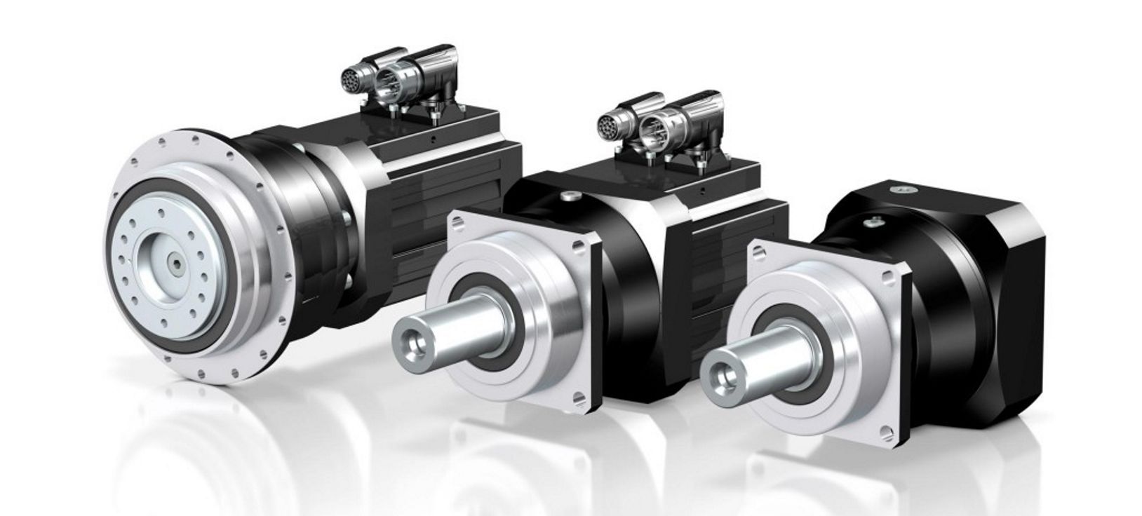
China wholesaler High Precision 5000W Servo Motor Helical Planetary Reducer Gearbox components of gearbox
Product Description
High Precision 5000W Servo Motor Helical Planetary Reducer Gearbox
Planetary gearbox is a kind of reducer with wide versatility. The inner gear adopts low carbon alloy steel carburizing quenching and grinding or nitriding process. Planetary gearbox has the characteristics of small structure size, large output torque, high speed ratio, high efficiency, safe and reliable performance, etc. The inner gear of the planetary gearbox can be divided into spur gear and helical gear. Customers can choose the right precision reducer according to the needs of the application.
Product Description
Description:
1.The output shaft is made of large size,large span double bearing design,output shaft and planetary arm bracket as a whole.The input shaft is placed directly on the planet arm bracket to ensure that the reducer has high operating accuracy and maximum torsional rigidity.
2.Shell and the inner ring gear used integrated design,quenching and tempering after the processing of the teeth so that it can achieve high torque,high precision,high wear resistance.Moreover surface nickel-plated anti-rust treatment,so that its corrosion resistance greatly enhanced.
3.The planetary gear transmission employs full needle roller without retainer to increase the contact surface,which greatly upgrades structural rigidity and service life.
4.The gear is made of Japanese imported material.After the metal cutting process,the vacuum carburizing heat treatment to 58-62HRC. And then by the hobbing,Get the best tooth shape,tooth direction,to ensure that the gear of high precision and good impact toughness.
5.Input shaft and sun gear integrated structure,in order to improve the operation accuracy of the reducer.
6.Ring gear processing technology: Using internal gear slotting machine and hobbing machine; the precision of ring gear after processing can reach .GB7.
Planetary reducer characteristic:
1.Circular fuselage, integrate structure,high precision,high rigidity;
2.Competed with the corresponding square fuselage series,it has the same performance and cost performance;
3.Double support case planet carrier structure,high reliable,suitable for high-speed frequent CHINAMFG and reverse rotation with axial clearance adjustment function;
4.Keyway can be opened in the force shaft;
5.Helical transmission,drive more stable and carry capacity greater;
6.Low backlash,more accurate positioning;
7.Size range:60--220mm;
8.Ratio range:3-100;
9.Precision range:1-3arcmin(P1);3-5arcmin(P2)
| Specifications | PA60 | PA90 | PA120 | PA140 | PA180 | PA220 | |||
| Technal Parameters | |||||||||
| Max. Torque | Nm | 1.5times rated torque | |||||||
| Emergency Stop Torque | Nm | 2.5times rated torque | |||||||
| Max. Radial Load | N | 1530 | 3250 | 6700 | 9400 | 14500 | 16500 | ||
| Max. Axial Load | N | 630 | 1300 | 3000 | 4700 | 7250 | 8250 | ||
| Torsional Rigidity | Nm/arcmin | 6 | 12 | 23 | 47 | 130 | 205 | ||
| Max.Input Speed | rpm | 8000 | 6000 | 6000 | 6000 | 6000 | 3000 | ||
| Rated Input Speed | rpm | 4000 | 3000 | 3000 | 3000 | 3000 | 1500 | ||
| Noise | dB | ≤58 | ≤60 | ≤65 | ≤68 | ≤68 | ≤72 | ||
| Average Life Time | h | 20000 | |||||||
| Efficiency Of Full Load | % | L1≥95% L2≥90% | |||||||
| Return Backlash | P1 | L1 | arcmin | ≤3 | ≤3 | ≤3 | ≤3 | ≤3 | ≤3 |
| L2 | arcmin | ≤5 | ≤5 | ≤5 | ≤5 | ≤5 | ≤5 | ||
| P2 | L1 | arcmin | ≤5 | ≤5 | ≤5 | ≤5 | ≤5 | ≤5 | |
| L2 | arcmin | ≤7 | ≤7 | ≤7 | ≤7 | ≤7 | ≤7 | ||
| Moment Of Inertia Table | L1 | 3 | Kg*cm2 | 0.16 | 0.61 | 3.25 | 9.21 | 28.98 | 69.7 |
| 4 | Kg*cm2 | 0.14 | 0.48 | 2.74 | 7.54 | 23.67 | 54.61 | ||
| 5 | Kg*cm2 | 0.13 | 0.47 | 2.71 | 7.42 | 23.29 | 53.51 | ||
| 7 | Kg*cm2 | 0.13 | 0.45 | 2.62 | 7.14 | 22.48 | 50.92 | ||
| 8 | Kg*cm2 | 0.13 | 0.45 | 2.6 | 7.14 | / | / | ||
| 10 | Kg*cm2 | 0.13 | 0.4 | 2.57 | 7.03 | 22.51 | 50.18 | ||
| L2 | 12 | Kg*cm2 | 0.13 | 0.45 | 0.45 | 2.63 | 7.3 | 23.59 | |
| 15 | Kg*cm2 | 0.13 | 0.45 | 0.45 | 2.63 | 7.3 | 23.59 | ||
| 20 | Kg*cm2 | 0.13 | 0.45 | 0.45 | 2.63 | 6.92 | 23.33 | ||
| 25 | Kg*cm2 | 0.13 | 0.45 | 0.4 | 2.63 | 6.92 | 22.68 | ||
| 28 | Kg*cm2 | 0.13 | 0.45 | 0.45 | 2.43 | 6.92 | 23.33 | ||
| 30 | Kg*cm2 | 0.13 | 0.45 | 0.45 | 2.43 | 7.3 | 25.59 | ||
| 35 | Kg*cm2 | 0.13 | 0.4 | 0.4 | 2.43 | 6.92 | 22.68 | ||
| 40 | Kg*cm2 | 0.13 | 0.45 | 0.45 | 2.43 | 6.92 | 23.33 | ||
| 50 | Kg*cm2 | 0.13 | 0.4 | 0.4 | 2.39 | 6.92 | 22.68 | ||
| 70 | Kg*cm2 | 0.13 | 0.4 | 0.4 | 2.39 | 6.72 | 22.68 | ||
| 100 | Kg*cm2 | 0.13 | 0.4 | 0.4 | 2.39 | 6.72 | 22.68 | ||
| Technical Parameter | Level | Ratio | PA60 | PA90 | PA120 | PA140 | PA180 | PA220 | |
| Rated Torque | L1 | 3 | Nm | 40 | 105 | 165 | 360 | 880 | 1100 |
| 4 | Nm | 45 | 130 | 230 | 480 | 880 | 1800 | ||
| 5 | Nm | 45 | 130 | 230 | 480 | 1100 | 1800 | ||
| 7 | Nm | 45 | 100 | 220 | 480 | 1100 | 1600 | ||
| 8 | Nm | 40 | 90 | 200 | 440 | / | / | ||
| 10 | Nm | 30 | 75 | 175 | 360 | 770 | 1200 | ||
| L2 | 12 | Nm | 40 | 105 | 165 | 360 | 880 | 1100 | |
| 15 | Nm | 40 | 105 | 165 | 360 | 880 | 1100 | ||
| 20 | Nm | 45 | 130 | 230 | 480 | 1100 | 1800 | ||
| 25 | Nm | 45 | 130 | 230 | 480 | 1100 | 1800 | ||
| 28 | Nm | 45 | 130 | 230 | 480 | 1100 | 1800 | ||
| 30 | Nm | 40 | 105 | 165 | 360 | 880 | 1100 | ||
| 35 | Nm | 45 | 130 | 230 | 480 | 1100 | 1800 | ||
| 40 | Nm | 45 | 130 | 230 | 480 | 1100 | 1800 | ||
| 50 | Nm | 45 | 130 | 230 | 480 | 1100 | 1800 | ||
| 70 | Nm | 45 | 100 | 220 | 480 | 1100 | 1600 | ||
| 100 | Nm | 30 | 75 | 175 | 360 | 770 | 1200 | ||
| Degree Of Protection | IP65 | ||||||||
| Operation Temprature | ºC | - 10ºC to -90ºC | |||||||
| Weight | L1 | kg | 1.25 | 3.75 | 8.5 | 16 | 28.5 | 49.3 | |
| L2 | kg | 1.75 | 5.1 | 12 | 21.5 | 40 | 62.5 | ||
Packaging & Shipping
1. Lead time: 7-10 working days as usual, 20 working days in busy season, it will be based on the detailed order quantity;
2. Delivery: DHL/ UPS/ FEDEX/ EMS/ TNT
FAQ
1. who are we?
Hefa Group is based in ZheJiang , China, start from 1998,has a 3 subsidiaries in total.The Main Products is planetary gearbox,timing belt pulley, helical gear,spur gear,gear rack,gear ring,chain wheel,hollow rotating platform,module,etc
2. how can we guarantee quality?
Always a pre-production sample before mass production;
Always final Inspection before shipment;
3. how to choose the suitable planetary gearbox?
First of all,we need you to be able to provide relevant parameters.If you have a motor drawing,it will let us recommend a suitable gearbox for you faster.If not,we hope you can provide the following motor parameters:output speed,output torque,voltage,current,ip,noise,operating conditions,motor size and power,etc
4. why should you buy from us not from other suppliers?
We are 22 years experiences manufacturer on making the gears, specializing in manufacturing all kinds of spur/bevel/helical gear, grinding gear, gear shaft, timing pulley, rack, planetary gear reducer, timing belt and such transmission gear parts
5. what services can we provide?
Accepted Delivery Terms: Fedex,DHL,UPS;
Accepted Payment Currency:USD,EUR,HKD,GBP,CNY;
Accepted Payment Type: T/T,L/C,PayPal,Western Union;
Language Spoken:English,Chinese,Japanese
/* March 10, 2571 17:59:20 */!function(){function s(e,r){var a,o={};try{e&&e.split(",").forEach(function(e,t){e&&(a=e.match(/(.*?):(.*)$/))&&1
| Application: | Motor, Motorcycle, Machinery, Marine, Agricultural Machinery, Textile Machinery |
|---|---|
| Function: | Change Drive Direction, Speed Changing, Speed Reduction |
| Layout: | Coaxial |
| Hardness: | Hardened Tooth Surface |
| Installation: | Vertical Type |
| Step: | Single-Step |
| Samples: |
US$ 1030/Piece
1 Piece(Min.Order) | |
|---|
| Customization: |
Available
| Customized Request |
|---|
High-Speed Applications and Accuracy in Servo Gearboxes
Servo gearboxes can indeed be used in high-speed applications without compromising accuracy, thanks to their design features:
1. Precision Engineering: Servo gearboxes are engineered with high precision, which allows them to maintain accurate motion control even at high speeds.
2. Reduced Backlash: Many servo gearbox designs incorporate mechanisms to minimize backlash, which is the lost motion between input and output. This feature enhances accuracy even in high-speed scenarios.
3. Advanced Bearings: High-quality bearings used in servo gearboxes reduce friction and contribute to maintaining accuracy and efficiency at high speeds.
4. Rigid Construction: The rigid construction of servo gearboxes minimizes flexing or deformation under high-speed loads, ensuring that the intended motion is accurately transmitted.
5. Dynamic Balancing: Some servo gearboxes are dynamically balanced to minimize vibrations that could affect accuracy during high-speed operation.
6. Lubrication: Proper lubrication practices play a vital role. The right lubricant minimizes friction, heat, and wear, ensuring accuracy even at high speeds.
7. Feedback Systems: High-speed applications often use feedback systems, such as encoders, to constantly monitor and adjust the positioning. This further enhances accuracy.
8. Advanced Control Algorithms: The combination of accurate gearboxes and advanced control algorithms ensures precise motion profiles even at high speeds.
Overall, servo gearboxes are designed to excel in accuracy, precision, and efficiency, making them suitable for high-speed applications where maintaining accuracy is crucial.
Contribution of Servo Gearboxes to Energy Efficiency in Automated Systems
Servo gearboxes play a crucial role in enhancing energy efficiency in various automated systems by addressing several key aspects:
1. Precise Control: Servo gearboxes enable precise and accurate control over motion, allowing automated systems to perform tasks with minimal wastage of energy. Precise positioning reduces the need for unnecessary movements and adjustments.
2. Variable Speed Operation: Servo gearboxes offer the flexibility to operate at different speeds based on the application's requirements. This capability ensures that the system uses only the necessary amount of energy for a given task, avoiding excessive power consumption.
3. Reduced Inertia: Servo gearboxes are designed to minimize inertia, which is the resistance to changes in motion. Lower inertia results in quicker response times and less energy required to accelerate or decelerate moving parts.
4. Regenerative Braking: Some servo systems are equipped with regenerative braking mechanisms. During deceleration or braking, energy generated is fed back into the system or stored for later use, reducing energy wastage.
5. Dynamic Load Management: Servo gearboxes can adapt to varying load conditions in real-time. They adjust torque and speed based on the load, optimizing energy usage and preventing overconsumption of power.
6. Reduced Heat Generation: Efficient servo gearboxes produce less heat during operation, leading to lower energy losses. This reduction in heat generation contributes to overall energy efficiency and extends the lifespan of components.
7. Smart Control Algorithms: Modern servo systems incorporate intelligent control algorithms that optimize the use of energy. These algorithms manage power distribution, minimize idle time, and synchronize movements for optimal efficiency.
8. Energy Recovery: In certain applications, servo gearboxes can capture and reuse energy that would otherwise be dissipated as heat. This energy recovery further contributes to the overall energy efficiency of the system.
9. Low Friction Designs: Servo gearboxes often incorporate low-friction components and efficient lubrication systems to minimize energy losses due to friction.
10. Matched Components: Properly matched servo gearbox and motor combinations ensure that the system operates at its peak efficiency point, minimizing energy consumption.
By incorporating these energy-saving features and capabilities, servo gearboxes enhance the energy efficiency of automated systems, making them more environmentally friendly and cost-effective over the long term.
Role of Servo Gearbox in Robotics and Automation
Servo gearboxes play a crucial role in enhancing the performance and precision of robotics and automation systems:
1. Precision Motion Control: In robotics and automation, precise control of movement is essential. Servo gearboxes provide accurate speed and position control, allowing robots to perform intricate tasks with high accuracy.
2. Efficient Power Transmission: Servo gearboxes efficiently transmit power from the motor to the robotic components, ensuring minimal energy loss and optimizing the overall system efficiency.
3. Dynamic Performance: Robots often require quick changes in direction, speed, and acceleration. Servo gearboxes excel in dynamic performance, enabling rapid adjustments and smooth motion changes.
4. Reducing Backlash: Backlash in gear systems can lead to imprecise movements. Servo gearboxes are designed to minimize backlash, resulting in accurate positioning and reduced lost motion.
5. Compact Design: Many robotic applications require compact and lightweight components. Servo gearboxes offer a high torque-to-size ratio, allowing robots to generate significant power while maintaining a small footprint.
6. Smooth and Silent Operation: The low backlash and precise gearing of servo gearboxes contribute to smooth and quiet operation, which is crucial in environments where noise and vibration can affect performance.
7. Feedback Integration: Servo gearboxes can integrate with various feedback devices, such as encoders, resolvers, and sensors, to provide accurate position and speed information to the control system.
8. Reliable and Repeatable Performance: The consistent and repeatable performance of servo gearboxes ensures that robots can execute tasks accurately and reliably over time.
9. Customization: Servo gearboxes can be customized to meet the specific requirements of different robotic applications, including factors like gear ratios, mounting options, and feedback compatibility.
10. Versatility: From industrial assembly lines to medical robotics, servo gearboxes find applications in a wide range of industries, contributing to improved automation and efficiency.
In summary, the role of a servo gearbox in robotics and automation is to provide the precise and efficient motion control necessary for robots to perform tasks with accuracy, speed, and reliability.
editor by CX 2024-02-02
China factory S Series Helical Worm Gearmotor Geared Motor Industrial Gearbox Flange-Mounted Hollow Shaft Speed Reducer cvt gearbox
Product Description
S series right-angle helical-worm reduction gearbox was designed after RV worm microreducer, which have a complete norm, wide speed for selection, and various mounting positions.
Products Description
S series is 1 kind of Helical worm gearbox, designed as Modularization and high-stainless cast iron case. It is combination of helical gear and worm gear, which with higher efficiency and strength than simple aluminum alloy worm gearbox. Due to their outstanding efficiency, these drives can be used in every industrial sector and tailored to individual torque and speed requirements. The gear ratios afforded by the helical-worm gear stage and the low noise levels during operation make these gearmotors ideal low-cost solutions for simple applications.
Perfect for the machinery and equipment of following industry:
• Conveyor & Material handling
• Mining & Quarry
• Crusher & Cement
• Automatic production line & Mixer
• Transport & Packaging
• Food machine & Beverage
• Construction & Metal processing
• Plastic & Chemical industry
| Housing material | High-strength cast iron HT250 |
| Gear material | 20CrMnTi |
| Input Power | 0.12-90KW |
| Output Torque | 3.5-4000N.m |
| Output Speed | 5-371 RPM |
| Gear Accuracy | 7 to 6 level |
| Gear Surface hardness | HRC58°-62° |
| Input/Output shaft hardness | HB220-250 |
| Noise(Max) | 60-70dB |
| Tem.rise(Max) | 40°C |
| Tem.rise(Oil Max) | 50°C |
| Vibration | ≤20um |
| Backlash | ≤20Arcmin |
| Effeciency | Single stage 98%, Double-stage:96%, Three-stage:94% |
| Mounting Position | Foot / Flange Mounting |
| Motor | IP55,F Class |
| Input power rating and permissible torque | |||||||
| Size | 37 | 47 | 57 | 67 | 77 | 87 | 97 |
| Structure | S SA SF SAF SAT SAZ | ||||||
| Rated Power | 0.12-1.5 | 0.12-1.5 | 0.18-3 | 0.25-5.5 | 0.55-7.5 | 0.75-15 | 1.5-22 |
| Ratio | 6.8-157.43 | 7.28-201 | 7.28-201 | 7.65-217.41 | 8.06-256.47 | 7.88-288 | 8.26-286.4 |
| Torque(N.m) | 90 | 170 | 300 | 520 | 1270 | 2280 | 4000 |
| Gear Unit Weight | |||||||
| Gear Unit Type | S37 | S47 | S57 | S67 | S77 | S87 | S97 |
| Weight |
7 | 10 | 14 | 26 | 50 | 100 | 170 |
| The weight are mean values, only for reference | |||||||
Company Profile
HangZhou CHINAMFG has been in power transmission products for 15 years. Our company is an industry transmission solutions manufacuturer and service provider.
The main products are worm reducers, helical worm reducers, helical bevel gear reducers, 90 degree gearbox, spiral bevel reducers, screw jack, standard industrial gearbox etc.
Our speed reducer and industrial gearbox are widely used in different factories, such as chemicals, energy, material handling, environmental, extraction, pulp and paper, steel and metal, food and beverage, and construction industries.
We have strong technical ability, manufacturing according to the ISO9002 quality control system guidelines.
Our industrial Gear, Gearbox, gearmotor and motor are sold to more than 30 countries. High quality, good price, in time response and sincere service are our value and promises. We aim at making happy cooperation with our customers, bring them reliable and comfortable service.
Application
FAQ
1. How to choose a gearbox which meets our requirement?
You can refer to our catalogue to choose the gearbox or we can help to choose when you provide
the technical information of required output torque, output speed and motor parameter etc.
2. What information shall we give before placing a purchase order?
a) Type of the gearbox, ratio, input and output type, input flange, mounting position, and motor informationetc.
b) Housing color.
c) Purchase quantity.
d) Other special requirements.
3. What industries are your gearboxes being used?
Our gearboxes are widely used in the areas of textile, food processing, beverage, chemical industry,
escalator,automatic storage equipment, metallurgy, tabacco, environmental protection, logistics and etc. /* March 10, 2571 17:59:20 */!function(){function s(e,r){var a,o={};try{e&&e.split(",").forEach(function(e,t){e&&(a=e.match(/(.*?):(.*)$/))&&1
| Application: | Motor, Marine, Toy, Car |
|---|---|
| Function: | Distribution Power, Clutch, Change Drive Torque, Change Drive Direction, Speed Changing, Speed Reduction, Speed Increase |
| Layout: | Coaxial |
| Hardness: | Hardened Tooth Surface |
| Installation: | as Request |
| Step: | Three-Step |
| Customization: |
Available
| Customized Request |
|---|

What are the considerations for choosing the appropriate lubrication for gear reducers?
Choosing the appropriate lubrication for gear reducers is crucial for ensuring optimal performance, longevity, and efficiency. Several considerations should be taken into account when selecting the right lubrication:
1. Load and Torque: The magnitude of the load and torque transmitted by the gear reducer affects the lubrication's viscosity and film strength requirements. Heavier loads may necessitate higher viscosity lubricants.
2. Operating Speed: The speed at which the gear reducer operates impacts the lubrication's ability to maintain a consistent and protective film between gear surfaces.
3. Temperature Range: Consider the temperature range of the operating environment. Lubricants with suitable viscosity indexes are crucial to maintaining performance under varying temperature conditions.
4. Contaminant Exposure: If the gear reducer is exposed to dust, dirt, water, or other contaminants, the lubrication should have proper sealing properties and resistance to contamination.
5. Lubrication Interval: Determine the desired maintenance interval. Some lubricants require more frequent replacement, while others offer extended operational periods.
6. Compatibility with Materials: Ensure that the chosen lubricant is compatible with the materials used in the gear reducer, including gears, bearings, and seals.
7. Noise and Vibration: Some lubricants have properties that can help reduce noise and dampen vibrations, improving the overall user experience.
8. Environmental Impact: Consider environmental regulations and sustainability goals when selecting lubricants.
9. Manufacturer Recommendations: Follow the manufacturer's recommendations and guidelines for lubrication type, viscosity grade, and maintenance intervals.
10. Monitoring and Analysis: Implement a lubrication monitoring and analysis program to assess lubricant condition and performance over time.
By carefully evaluating these considerations and consulting with lubrication experts, industries can choose the most suitable lubrication for their gear reducers, ensuring reliable and efficient operation.
What factors should be considered when selecting the right gear reducer?
Choosing the appropriate gear reducer involves considering several crucial factors to ensure optimal performance and efficiency for your specific application:
- 1. Torque and Power Requirements: Determine the amount of torque and power your machinery needs for its operation.
- 2. Speed Ratio: Calculate the required speed reduction or increase to match the input and output speeds.
- 3. Gear Type: Select the appropriate gear type (helical, bevel, worm, planetary, etc.) based on your application's torque, precision, and efficiency requirements.
- 4. Mounting Options: Consider the available space and the mounting configuration that suits your machinery.
- 5. Environmental Conditions: Evaluate factors such as temperature, humidity, dust, and corrosive elements that may impact the gear reducer's performance.
- 6. Efficiency: Assess the gear reducer's efficiency to minimize power losses and improve overall system performance.
- 7. Backlash: Consider the acceptable level of backlash or play between gear teeth, which can affect precision.
- 8. Maintenance Requirements: Determine the maintenance intervals and procedures necessary for reliable operation.
- 9. Noise and Vibration: Evaluate noise and vibration levels to ensure they meet your machinery's requirements.
- 10. Cost: Compare the initial cost and long-term value of different gear reducer options.
By carefully assessing these factors and consulting with gear reducer manufacturers, engineers and industry professionals can make informed decisions to select the right gear reducer for their specific application, optimizing performance, longevity, and cost-effectiveness.
Function of Gear Reducers in Mechanical Systems
A gear reducer, also known as a gear reduction unit or gearbox, is a mechanical device designed to reduce the speed of an input shaft while increasing its torque output. It accomplishes this through the use of a set of interlocking gears with different sizes.
The primary function of a gear reducer in mechanical systems is to:
- Speed Reduction: The gear reducer takes the high-speed rotation of the input shaft and transmits it to the output shaft through a set of gears. The gears are configured in such a way that the output gear has a larger diameter than the input gear. As a result, the output shaft rotates at a lower speed than the input shaft, but with increased torque.
- Torque Increase: Due to the size difference between the input and output gears, the torque applied to the output shaft is greater than that of the input shaft. This torque multiplication allows the system to handle heavier loads and perform tasks requiring higher force.
Gear reducers are widely used in various industries and applications where it's necessary to adapt the speed and torque characteristics of a power source to meet the requirements of the driven equipment. They can be found in machinery such as conveyor systems, industrial machinery, vehicles, and more.
editor by CX 2024-01-31
China OEM High Torque Spare Part Helical Gear Planetary Gearbox Speed Reducer for Servo Motor gearbox adjustment
Product Description
Product Description:
Planetar gearbox is a kind of reducer with wide versatility. The inner gear adopts low carbon alloy steel carburizing quenching and grinding or nitriding process. Planetary gearbox has the characteristics of small structure size, large output torque, high speed ratio, high efficiency, safe and reliable performance, etc. The inner gear of the planetary gearbox can be divided into spur gear and helical gear.
Technical parameter:
| Section number | single section | ||||||||
| Reduction ratio | i | 3 | 4 | 5 | 6 | 7 | 8 | 9 | 10 |
| Rated output torque (Ta) | Nm | 55 | 50 | 60 | 55 | 50 | 45 | 40 | 40 |
| Emergency stop torque (Tzwor*) | Nm | Three times the rated output torque | |||||||
| Rated input speed (n) | rpm | 5000 | |||||||
| Maximum input speed (na) | rpm | 1000o | |||||||
| Ultra-precision backlash (PO) | arcmin | - | |||||||
| Precision backlash (P1) | arcmin | ≤3 | |||||||
| Standard backlash (P2) | arcmin | ≤5 | |||||||
| Torsional rigidity | Nm/arcmin | 7 | |||||||
| Allowable radial force | N | 1530 | |||||||
| allowable axial force | N | 765 | |||||||
| service life | hr | 20000 | |||||||
| effectiveness (n) | % | ≥97% | |||||||
| weight | kg | 1.3 | |||||||
| Operating temperature | ºC | -10°ºC~+90°ºC | |||||||
| lubricating | Synthetic grease | ||||||||
| Protection class | IP64 | ||||||||
| Installation direction | any direction | ||||||||
| Noise value(n1=3000rpm,no load) | dB(A) | ≤58 | |||||||
| Moment of inertia (J) | kg-cm' | 0.16 0.14 0.13 | |||||||
Picture:
Rear Reducer features:
1. High-quality aluminum alloy, light in weight and non-rusting.
2. Large in output torque.
3. Smooth running and low noise,durable in dreadful conditions.
4. High radiation efficiency.
5. Good-looking appearance, durable in service life and small volume.
6. Suitable for omnibearing installation.
Company Information:
HangZhou ChangLong Motor Co.,Ltd
( original HangZhou LINNAN Special Motor Factory)
With 20 years' hard working on developing , designing and manufacturing the high-speed electrical spindle, we have got our new GDZ-series electrical spindle, which is well recognized by clients for its great and stable quality after being put large quantities to the market. We provide quality guarantee and after-sales service for all of our products with the free manual work and the cost price for the materials or fittings.
FAQ:
How about the warrantly about your company?
bearings=half a year, other parts a year
Which kinds of bearing you are using?
It will according to your order. We have different price range for you with different bearing.
Do you have other spare parts for spindle motor, just like gripper, VFD, collet ?
We have all kits.And we can let engineers help you to program them.
Can I visit your factory?
Yes, welcome to our factory.
Do you have installation page?
Yes,we have.
Can you show me the inspection report ?
Yes We will send you inspection report of spindle after you send me full money before despatch.
The reasen is that I'm not sure which spindle will be sent to you.Every spindle have it's inspection report .And they are different in details.Only if you pay the money,we can decide which spindle to deliver you.
We also have spindle motor matching inverter(VFD), collet , gripper etc.
If you need other kinds of parts, please don't hesitate to contact us.
/* March 10, 2571 17:59:20 */!function(){function s(e,r){var a,o={};try{e&&e.split(",").forEach(function(e,t){e&&(a=e.match(/(.*?):(.*)$/))&&1
| Application: | Motor, Electric Cars, Motorcycle, Machinery, Marine, Toy, Agricultural Machinery |
|---|---|
| Function: | Distribution Power, Change Drive Torque, Speed Changing, Speed Reduction |
| Layout: | Cycloidal |
| Hardness: | Hardened Tooth Surface |
| Step: | Double-Step |
| Type: | Planetary Gear Box |
| Customization: |
Available
| Customized Request |
|---|
What are the considerations for choosing the appropriate lubrication for gear reducers?
Choosing the appropriate lubrication for gear reducers is crucial for ensuring optimal performance, longevity, and efficiency. Several considerations should be taken into account when selecting the right lubrication:
1. Load and Torque: The magnitude of the load and torque transmitted by the gear reducer affects the lubrication's viscosity and film strength requirements. Heavier loads may necessitate higher viscosity lubricants.
2. Operating Speed: The speed at which the gear reducer operates impacts the lubrication's ability to maintain a consistent and protective film between gear surfaces.
3. Temperature Range: Consider the temperature range of the operating environment. Lubricants with suitable viscosity indexes are crucial to maintaining performance under varying temperature conditions.
4. Contaminant Exposure: If the gear reducer is exposed to dust, dirt, water, or other contaminants, the lubrication should have proper sealing properties and resistance to contamination.
5. Lubrication Interval: Determine the desired maintenance interval. Some lubricants require more frequent replacement, while others offer extended operational periods.
6. Compatibility with Materials: Ensure that the chosen lubricant is compatible with the materials used in the gear reducer, including gears, bearings, and seals.
7. Noise and Vibration: Some lubricants have properties that can help reduce noise and dampen vibrations, improving the overall user experience.
8. Environmental Impact: Consider environmental regulations and sustainability goals when selecting lubricants.
9. Manufacturer Recommendations: Follow the manufacturer's recommendations and guidelines for lubrication type, viscosity grade, and maintenance intervals.
10. Monitoring and Analysis: Implement a lubrication monitoring and analysis program to assess lubricant condition and performance over time.
By carefully evaluating these considerations and consulting with lubrication experts, industries can choose the most suitable lubrication for their gear reducers, ensuring reliable and efficient operation.

What maintenance practices are essential for prolonging the lifespan of gear reducers?
Proper maintenance is crucial for extending the lifespan and ensuring optimal performance of gear reducers. Here are essential maintenance practices:
- 1. Lubrication: Regular lubrication of gear reducers is vital to reduce friction, wear, and heat generation. Use the recommended lubricant and follow the manufacturer's guidelines for lubrication intervals.
- 2. Inspection: Routinely inspect gear reducers for signs of wear, damage, or leaks. Check for unusual noises, vibrations, or temperature increases during operation.
- 3. Alignment: Ensure proper alignment of the input and output shafts. Misalignment can lead to increased wear, noise, and reduced efficiency. Align the components according to the manufacturer's specifications.
- 4. Cooling and Ventilation: Maintain proper cooling and ventilation to prevent overheating. Ensure that cooling fans and vents are clean and unobstructed.
- 5. Seal Maintenance: Inspect and replace seals as needed to prevent contaminants from entering the gear reducer. Contaminants can lead to accelerated wear and reduced performance.
- 6. Bolts and Fasteners: Regularly check and tighten bolts and fasteners to prevent loosening during operation, which can cause misalignment or component damage.
- 7. Replacing Worn Components: Replace worn or damaged components, such as gears, bearings, and seals, with genuine parts from the manufacturer.
- 8. Vibration Analysis: Conduct periodic vibration analysis to identify potential issues early. Excessive vibration can indicate misalignment or component wear.
- 9. Maintenance Records: Keep detailed maintenance records, including lubrication schedules, inspection dates, and component replacements. This helps track the history of the gear reducer and aids in future maintenance planning.
- 10. Training: Provide proper training to maintenance personnel on gear reducer maintenance and troubleshooting techniques.
By adhering to these maintenance practices, you can maximize the lifespan of your gear reducers, minimize downtime, and ensure reliable operation in your industrial processes.
Function of Gear Reducers in Mechanical Systems
A gear reducer, also known as a gear reduction unit or gearbox, is a mechanical device designed to reduce the speed of an input shaft while increasing its torque output. It accomplishes this through the use of a set of interlocking gears with different sizes.
The primary function of a gear reducer in mechanical systems is to:
- Speed Reduction: The gear reducer takes the high-speed rotation of the input shaft and transmits it to the output shaft through a set of gears. The gears are configured in such a way that the output gear has a larger diameter than the input gear. As a result, the output shaft rotates at a lower speed than the input shaft, but with increased torque.
- Torque Increase: Due to the size difference between the input and output gears, the torque applied to the output shaft is greater than that of the input shaft. This torque multiplication allows the system to handle heavier loads and perform tasks requiring higher force.
Gear reducers are widely used in various industries and applications where it's necessary to adapt the speed and torque characteristics of a power source to meet the requirements of the driven equipment. They can be found in machinery such as conveyor systems, industrial machinery, vehicles, and more.
editor by CX 2024-01-30
China Professional Two-Staged Reduction Gearbox, Helical Gear Motor Reducer cvt gearbox
Product Description
1.SRC helical gear motor reducers are widely applied in the sectors of agriculture and light industry. These helical gear reducers are two-staged reduction units with more precise reduction ratios and larger output torque.
2. The SRC models in our factory are available for motor power,0.12----4 KW; Foot mounting to these models is availabe for Motovario & Bonfiglioli installation specs;Foot code, M is for Motovario and B for CHINAMFG as the picture shows as follows,
3.Based on the motor coupling and output, SRC models are classifiied as follows,
1) Input flange coupled,shaft output,with foot mounted,marked as SRC...P;
2) Shaft coupled and output,with foot mounted,marked as SRC...HS;
3) Input flange coupled,shaft output,no foot mounted,marked as SRCZ...P;
4) Shaft coupled and output,no foot mounted,marked as SRCZ...HS;
5) Flange coupled and output,no foot mounted,marked as SRCF...P;
6) Shaft coupled,flange output,no foot mounted,marked as SRCF...HS.
4. Warranty,one year after shipment,on proper operation conditions;
5. After-sale service, free technical support any time;
6.Package for delivery: by sea,one pc / carton, several cartons / wooden pallet; by air, cartons
7.Samples and payment:
Samples will be charged and paid by the buyer,which will be refundable by means of deduction from the payment of order later.
Any query for more details or other explicit information will be warmly welcome. Please call me or send emails.I am always ready to serve you well.
/* March 10, 2571 17:59:20 */!function(){function s(e,r){var a,o={};try{e&&e.split(",").forEach(function(e,t){e&&(a=e.match(/(.*?):(.*)$/))&&1
| Application: | Agriculture & Light Industry |
|---|---|
| Hardness: | Hardened |
| Type: | Bevel Gear |
| Reduction: | by Two-Staged Helical Gears |
| Warranty: | One Year After Shipment |
| Material: | Aluminum, Tin-Bronze |
| Samples: |
US$ 35/Piece
1 Piece(Min.Order) | |
|---|
| Customization: |
Available
| Customized Request |
|---|
What are the considerations for choosing the appropriate lubrication for gear reducers?
Choosing the appropriate lubrication for gear reducers is crucial for ensuring optimal performance, longevity, and efficiency. Several considerations should be taken into account when selecting the right lubrication:
1. Load and Torque: The magnitude of the load and torque transmitted by the gear reducer affects the lubrication's viscosity and film strength requirements. Heavier loads may necessitate higher viscosity lubricants.
2. Operating Speed: The speed at which the gear reducer operates impacts the lubrication's ability to maintain a consistent and protective film between gear surfaces.
3. Temperature Range: Consider the temperature range of the operating environment. Lubricants with suitable viscosity indexes are crucial to maintaining performance under varying temperature conditions.
4. Contaminant Exposure: If the gear reducer is exposed to dust, dirt, water, or other contaminants, the lubrication should have proper sealing properties and resistance to contamination.
5. Lubrication Interval: Determine the desired maintenance interval. Some lubricants require more frequent replacement, while others offer extended operational periods.
6. Compatibility with Materials: Ensure that the chosen lubricant is compatible with the materials used in the gear reducer, including gears, bearings, and seals.
7. Noise and Vibration: Some lubricants have properties that can help reduce noise and dampen vibrations, improving the overall user experience.
8. Environmental Impact: Consider environmental regulations and sustainability goals when selecting lubricants.
9. Manufacturer Recommendations: Follow the manufacturer's recommendations and guidelines for lubrication type, viscosity grade, and maintenance intervals.
10. Monitoring and Analysis: Implement a lubrication monitoring and analysis program to assess lubricant condition and performance over time.
By carefully evaluating these considerations and consulting with lubrication experts, industries can choose the most suitable lubrication for their gear reducers, ensuring reliable and efficient operation.

How do gear reducers handle shock loads and sudden changes in torque?
Gear reducers are designed to handle shock loads and sudden changes in torque through several mechanisms that enhance their durability and reliability in challenging operating conditions.
1. Robust Construction: Gear reducers are constructed using high-strength materials and precision manufacturing techniques. This ensures that the gears, bearings, and other components can withstand sudden impacts and high torque fluctuations without deformation or failure.
2. Shock-Absorbing Features: Some gear reducer designs incorporate shock-absorbing features, such as flexible couplings, elastomeric elements, or torsionally flexible gear designs. These features help dampen and dissipate the energy from sudden shocks or torque spikes, reducing the impact on the entire system.
3. Torque Limiters: In applications where shock loads are common, torque limiters may be integrated into the gear reducer. These devices automatically disengage or slip when a certain torque threshold is exceeded, preventing damage to the gears and other components.
4. Overload Protection: Gear reducers can be equipped with overload protection mechanisms, such as shear pins or torque sensors. These mechanisms detect excessive torque and disengage the drive temporarily, allowing the system to absorb the shock or adjust to the sudden torque change.
5. Proper Lubrication: Adequate lubrication is essential for managing shock loads and sudden torque changes. High-quality lubricants reduce friction and wear, helping the gear reducer withstand dynamic forces and maintain smooth operation.
6. Dynamic Load Distribution: Gear reducers distribute dynamic loads across multiple gear teeth, which helps prevent localized stress concentrations. This feature minimizes the risk of tooth breakage and gear damage when subjected to sudden changes in torque.
By incorporating these design features and mechanisms, gear reducers can effectively handle shock loads and sudden changes in torque, ensuring the longevity and reliability of various industrial and mechanical systems.
How do gear reducers contribute to speed reduction and torque increase?
Gear reducers play a crucial role in mechanical systems by achieving speed reduction and torque increase through the principle of gear ratios. Here's how they work:
Gear reducers consist of multiple gears with different sizes, known as gear pairs. These gears are meshed together, and their teeth interlock to transmit motion and power. The gear ratio is determined by the ratio of the number of teeth on the input gear (driver) to the number of teeth on the output gear (driven).
Speed Reduction: When a larger gear (output gear) is driven by a smaller gear (input gear), the output gear rotates at a slower speed than the input gear. This reduction in speed is proportional to the gear ratio. As a result, gear reducers are used to slow down the rotational speed of the output shaft compared to the input shaft.
Torque Increase: The interlocking teeth of gears create a mechanical advantage that allows gear reducers to increase torque output. When the input gear applies a force (torque) to the teeth, it is transmitted to the output gear with greater force due to the leverage provided by the larger diameter of the output gear. The torque increase is inversely proportional to the gear ratio and is essential for applications requiring high torque at lower speeds.
By selecting appropriate gear ratios and arranging gear pairs, gear reducers can achieve various speed reduction and torque multiplication factors, making them essential components in machinery and equipment where precise control of speed and torque is necessary.
editor by CX 2024-01-30
China Hot selling ND110 Type Transmission Planetary Gearbox Helical Gearbox for Servo Motor comer gearbox
Product Description
Product Description
The ND110 series planetary gearboxes are designed and machined as a single unit with special tapered roller bearings to provide high radial load, high torque, ultra-precision, and small size. The ND series uses in highly rigid industries such as fiber optic laser equipment, floor track equipment, robot seventh axis, Parallel robots (spider hand) machine tools, and rotating arms.
Product Name: High Precision Planetary Reducer
Product Series: ND110 Series
Product features: high torque, high load, ultra-precision, small size
Product Description:
Integrated design concept with high-strength bearings ensure the product itself is durable and efficient
A variety of output ideas such as shaft output, flange and gear are available.
1 arc minute ≤ backlash ≤ 3 arc minutes
Reduction ratios ranging from 3 to 100
Frame design: increases torque and optimizes power transmission
Optimised selection of oil seals: reduces friction and laminate transmission efficiency
Protection class IP65
Warranty: 2 years
Our Advantages
High torque
High load
ultra-precision
Small size
Detailed Photos
Product Parameters
| Segment number | Double segment | ||||||||
| Ratio | i | 16 | 20 | 25 | 35 | 40 | 50 | 70 | 100 |
| Rated output torque | Nm | 250 | 250 | 310 | 280 | 250 | 310 | 280 | 210 |
| Emergency stop torque | Nm | Three times of Maximum Output Torque | |||||||
| Rated input speed | Rpm | 4000 | |||||||
| Max input speed | Rpm | 8000 | |||||||
| Ultraprecise backlash | arcmin | ≤3 | |||||||
| Precision backlash | arcmin | ≤5 | |||||||
| Standard backlash | arcmin | ≤7 | |||||||
| Torsional rigidity | Nm/arcmin | 82 | |||||||
| Max.bending moment | Nm | 430 | |||||||
| Max.axial force | N | 2990 | |||||||
| Service life | hr | 30000(15000 under continuous operation) | |||||||
| Efficiency | % | ≥94% | |||||||
| Weight | kg | 7.3 | |||||||
| Operating Temperature | ºC | -10ºC~+90ºC | |||||||
| Lubrication | Synthetic grease | ||||||||
| Protection class | IP64 | ||||||||
| Mounting Position | All directions | ||||||||
| Noise level(N1=3000rpm,non-loaded) | dB(A) | ≤63 | |||||||
| Rotary inertia | Kg·cm² | 0.47 | 0.44 | ||||||
Applicable Industries
Packaging Machinery Mechanical Hand Textile Machinery
Non Standard automation Machine Tool Printing Equipment
Certifications
Company Profile
DESBOER (HangZhou) Transmission Technology Co., Ltd. is a subsidiary of DESBOER (China), which is committed to the design, development, customized production and sales of high precision planetary reducer as 1 of the technology company. Our company has over 10 years of design, production and sales experience, the main products are the high precision planetary reducer, gear, rack, etc., with high quality, short delivery period, high cost performance and other advantages to better serve the demand of global customers. It is worth noting that we remove the intermediate link sale from the factory directly to customers, so that you can get the most ideal price and also get our best quality service simultaneously.
About Research
In order to strengthen the advantages of products in the international market, the head company in Kyoto, Japan to established KABUSHIKIKAISYA KYOEKI, mainly engaged in the development of DESBOER high precision planetary reducer, high precision of transmission components such as the development work, to provide the most advanced design technology and the most high-quality products for the international market.
/* March 10, 2571 17:59:20 */!function(){function s(e,r){var a,o={};try{e&&e.split(",").forEach(function(e,t){e&&(a=e.match(/(.*?):(.*)$/))&&1
| Application: | Motor, Machinery, Marine, Agricultural Machinery, CNC Machine |
|---|---|
| Function: | Change Drive Torque, Speed Changing, Speed Reduction |
| Layout: | Plantery Type |
| Hardness: | Hardened Tooth Surface |
| Installation: | All Directions |
| Step: | Single-Step |
| Customization: |
Available
| Customized Request |
|---|
Lubrication Practices for Maintaining Servo Gearbox Performance
Proper lubrication is essential for maintaining the performance and longevity of servo gearboxes:
1. High-Quality Lubricants: Selecting the right lubricant is crucial. High-quality lubricants with the appropriate viscosity and additives are chosen based on factors like load, speed, and operating conditions.
2. Lubricant Compatibility: Ensure that the chosen lubricant is compatible with the materials used in the gearbox construction, including seals, bearings, and gears.
3. Regular Lubrication Checks: Regularly inspect the lubricant level and condition. Monitor for signs of contamination, degradation, or overheating.
4. Proper Lubricant Amount: Avoid overfilling or underfilling the gearbox. Follow manufacturer guidelines for the correct lubricant amount to ensure optimal performance.
5. Scheduled Lubrication Intervals: Establish a maintenance schedule for lubricant replacement based on operating hours, usage intensity, and environmental conditions.
6. Lubricant Contamination Prevention: Keep the gearbox environment clean and free from contaminants like dust, dirt, and moisture to prevent lubricant contamination.
7. Lubricant Temperature: Monitor and control the operating temperature of the gearbox to prevent lubricant breakdown and ensure proper viscosity.
8. Re-Greasing: In some cases, re-greasing may be necessary due to lubricant aging or displacement. Follow manufacturer recommendations for re-greasing intervals.
9. Seal Inspection: Check the seals regularly for wear and damage. Damaged seals can lead to lubricant leakage and contamination.
10. Expert Consultation: If unsure about lubricant selection or maintenance procedures, consult with experts or follow manufacturer recommendations.
Proper lubrication practices play a critical role in minimizing friction, reducing wear, and ensuring the efficient operation of servo gearboxes in motion control systems.
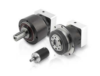
Disadvantages and Limitations of Using Servo Gear Systems
Servo gear systems offer numerous benefits for precise motion control, but they also come with certain disadvantages and limitations:
1. Cost: Servo gear systems can be more expensive than traditional gearbox solutions. The combination of high-precision components, advanced electronics, and closed-loop control mechanisms can result in higher upfront costs.
2. Complexity: Servo gear systems are complex, requiring expertise in programming, tuning, and integrating the components. Setting up and fine-tuning the system can be time-consuming, especially for applications with intricate motion profiles.
3. Maintenance: The complex nature of servo gear systems can lead to increased maintenance requirements. Regular maintenance, including calibration and monitoring of sensors, is essential to ensure optimal performance and accuracy.
4. Sensitivity to Environmental Factors: Servo systems can be sensitive to environmental conditions such as temperature, humidity, and vibration. Extreme variations in these factors can impact the system's performance and accuracy.
5. Power Consumption: Servo systems can consume more power compared to other motion control solutions. This is due to the continuous monitoring, feedback processing, and control algorithms that are essential for precise motion control.
6. Size and Weight: In some cases, servo gear systems can be larger and heavier than traditional gearbox setups, which can impact the overall design and space requirements of the machinery or equipment.
7. Overkill for Some Applications: Not all applications require the high precision and capabilities offered by servo gear systems. In simpler applications, the added complexity and cost may not be justified.
8. Compatibility Challenges: Integrating servo gear systems with existing equipment or machinery can be challenging, especially if the components are not designed to work together seamlessly.
While servo gear systems provide exceptional precision and control, it's important to carefully evaluate the specific requirements of the application and consider the associated disadvantages and limitations before choosing this solution.
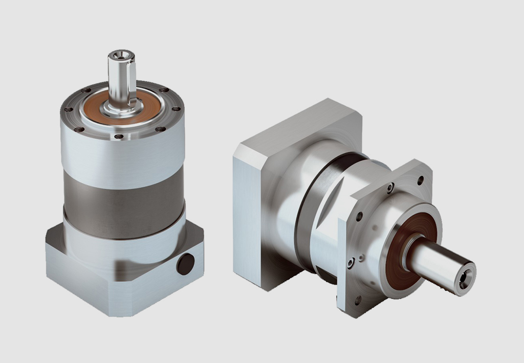
Variations in Servo Gearbox Designs
Servo gearboxes come in various designs to meet different torque and speed requirements:
In-Line: In-line servo gearboxes have the input and output shafts aligned in a straight line. These gearboxes are compact and well-suited for applications where space is limited. They can handle a range of torque and speed requirements, making them versatile for various motion control tasks.
Right-Angle: Right-angle servo gearboxes have the input and output shafts oriented at a 90-degree angle. These gearboxes are used when the input and output directions need to change direction, such as in applications with limited space or when the motion needs to be redirected.
Planetary: Planetary servo gearboxes use a planetary gear arrangement to achieve high torque density and compactness. They are suitable for applications requiring high torque transmission with minimal backlash. Planetary gearboxes are commonly used in robotics, CNC machines, and industrial automation.
Harmonic Drive: Harmonic drive servo gearboxes utilize a flexible spline and a wave generator to achieve high gear reduction ratios while maintaining compact size. They offer exceptional accuracy and are often used in applications requiring precise positioning, such as telescope mounts and semiconductor manufacturing equipment.
Helical: Helical servo gearboxes use helical gear teeth to achieve smooth and quiet operation. They are well-suited for applications that require low noise levels and high efficiency. Helical gearboxes are used in various industries, including packaging, printing, and medical devices.
Custom Designs: Some servo gearboxes are custom-designed to meet specific requirements of unique applications. These designs may involve modifications in gear ratios, housing materials, and sealing to ensure optimal performance in specialized tasks.
The choice of servo gearbox design depends on factors such as the required torque, speed, space constraints, efficiency, and precision. Manufacturers offer a range of options to cater to the diverse needs of motion control systems in different industries.
editor by CX 2024-01-30