Product Description
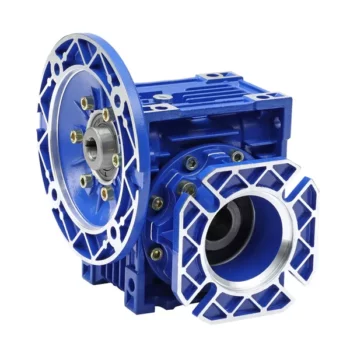
S series right-angle helical-worm reduction gearbox was designed after RV worm microreducer, which have a complete norm, wide speed for selection, and various mounting positions.
Products Description
S series is 1 kind of Helical worm gearbox, designed as Modularization and high-stainless cast iron case. It is combination of helical gear and worm gear, which with higher efficiency and strength than simple aluminum alloy worm gearbox. Due to their outstanding efficiency, these drives can be used in every industrial sector and tailored to individual torque and speed requirements. The gear ratios afforded by the helical-worm gear stage and the low noise levels during operation make these gearmotors ideal low-cost solutions for simple applications.
Perfect for the machinery and equipment of following industry:
• Conveyor & Material handling
• Mining & Quarry
• Crusher & Cement
• Automatic production line & Mixer
• Transport & Packaging
• Food machine & Beverage
• Construction & Metal processing
• Plastic & Chemical industry
| Housing material | High-strength cast iron HT250 |
| Gear material | 20CrMnTi |
| Input Power | 0.12-90KW |
| Output Torque | 3.5-4000N.m |
| Output Speed | 5-371 RPM |
| Gear Accuracy | 7 to 6 level |
| Gear Surface hardness | HRC58°-62° |
| Input/Output shaft hardness | HB220-250 |
| Noise(Max) | 60-70dB |
| Tem.rise(Max) | 40°C |
| Tem.rise(Oil Max) | 50°C |
| Vibration | ≤20um |
| Backlash | ≤20Arcmin |
| Effeciency | Single stage 98%, Double-stage:96%, Three-stage:94% |
| Mounting Position | Foot / Flange Mounting |
| Motor | IP55,F Class |
| Input power rating and permissible torque | |||||||
| Size | 37 | 47 | 57 | 67 | 77 | 87 | 97 |
| Structure | S SA SF SAF SAT SAZ | ||||||
| Rated Power | 0.12-1.5 | 0.12-1.5 | 0.18-3 | 0.25-5.5 | 0.55-7.5 | 0.75-15 | 1.5-22 |
| Ratio | 6.8-157.43 | 7.28-201 | 7.28-201 | 7.65-217.41 | 8.06-256.47 | 7.88-288 | 8.26-286.4 |
| Torque(N.m) | 90 | 170 | 300 | 520 | 1270 | 2280 | 4000 |
| Gear Unit Weight | |||||||
| Gear Unit Type | S37 | S47 | S57 | S67 | S77 | S87 | S97 |
| Weight |
7 | 10 | 14 | 26 | 50 | 100 | 170 |
| The weight are mean values, only for reference | |||||||
Company Profile
HangZhou CHINAMFG has been in power transmission products for 15 years. Our company is an industry transmission solutions manufacuturer and service provider.
The main products are worm reducers, helical worm reducers, helical bevel gear reducers, 90 degree gearbox, spiral bevel reducers, screw jack, standard industrial gearbox etc.
Our speed reducer and industrial gearbox are widely used in different factories, such as chemicals, energy, material handling, environmental, extraction, pulp and paper, steel and metal, food and beverage, and construction industries.
We have strong technical ability, manufacturing according to the ISO9002 quality control system guidelines.
Our industrial Gear, Gearbox, gearmotor and motor are sold to more than 30 countries. High quality, good price, in time response and sincere service are our value and promises. We aim at making happy cooperation with our customers, bring them reliable and comfortable service.
Application
FAQ
1. How to choose a gearbox which meets our requirement?
You can refer to our catalogue to choose the gearbox or we can help to choose when you provide
the technical information of required output torque, output speed and motor parameter etc.
2. What information shall we give before placing a purchase order?
a) Type of the gearbox, ratio, input and output type, input flange, mounting position, and motor informationetc.
b) Housing color.
c) Purchase quantity.
d) Other special requirements.
3. What industries are your gearboxes being used?
Our gearboxes are widely used in the areas of textile, food processing, beverage, chemical industry,
escalator,automatic storage equipment, metallurgy, tabacco, environmental protection, logistics and etc. /* March 10, 2571 17:59:20 */!function(){function s(e,r){var a,o={};try{e&&e.split(",").forEach(function(e,t){e&&(a=e.match(/(.*?):(.*)$/))&&1
| Application: | Motor, Marine, Toy, Car |
|---|---|
| Function: | Distribution Power, Clutch, Change Drive Torque, Change Drive Direction, Speed Changing, Speed Reduction, Speed Increase |
| Layout: | Coaxial |
| Hardness: | Hardened Tooth Surface |
| Installation: | as Request |
| Step: | Three-Step |
| Customization: |
Available
| Customized Request |
|---|
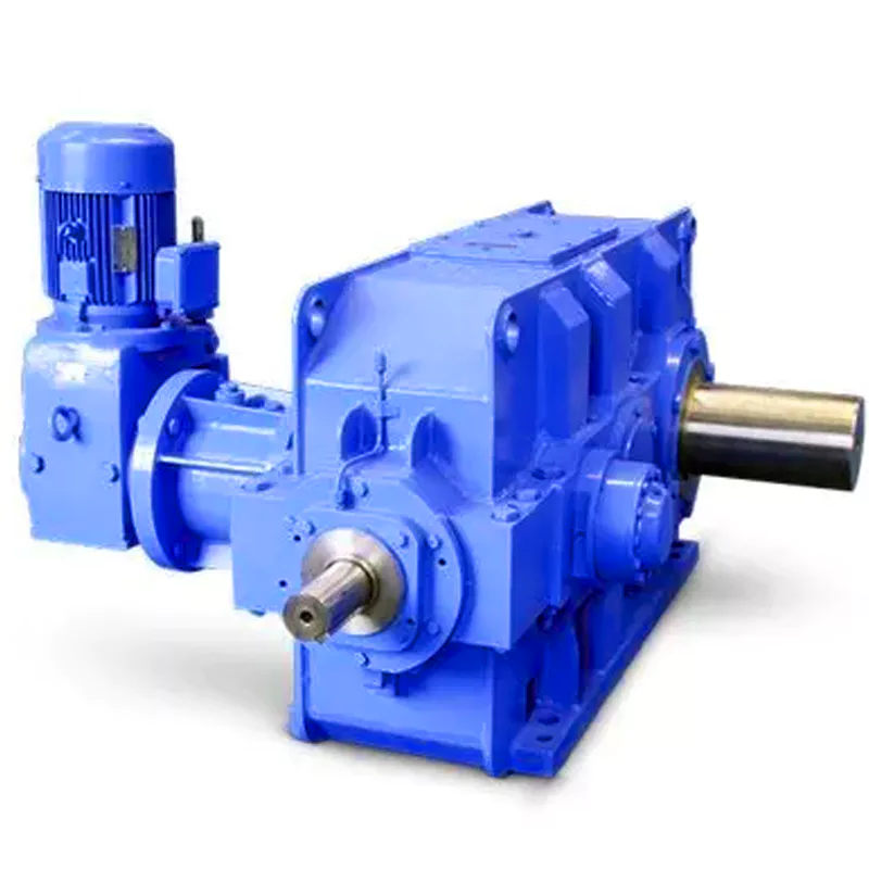
What are the considerations for choosing the appropriate lubrication for gear reducers?
Choosing the appropriate lubrication for gear reducers is crucial for ensuring optimal performance, longevity, and efficiency. Several considerations should be taken into account when selecting the right lubrication:
1. Load and Torque: The magnitude of the load and torque transmitted by the gear reducer affects the lubrication's viscosity and film strength requirements. Heavier loads may necessitate higher viscosity lubricants.
2. Operating Speed: The speed at which the gear reducer operates impacts the lubrication's ability to maintain a consistent and protective film between gear surfaces.
3. Temperature Range: Consider the temperature range of the operating environment. Lubricants with suitable viscosity indexes are crucial to maintaining performance under varying temperature conditions.
4. Contaminant Exposure: If the gear reducer is exposed to dust, dirt, water, or other contaminants, the lubrication should have proper sealing properties and resistance to contamination.
5. Lubrication Interval: Determine the desired maintenance interval. Some lubricants require more frequent replacement, while others offer extended operational periods.
6. Compatibility with Materials: Ensure that the chosen lubricant is compatible with the materials used in the gear reducer, including gears, bearings, and seals.
7. Noise and Vibration: Some lubricants have properties that can help reduce noise and dampen vibrations, improving the overall user experience.
8. Environmental Impact: Consider environmental regulations and sustainability goals when selecting lubricants.
9. Manufacturer Recommendations: Follow the manufacturer's recommendations and guidelines for lubrication type, viscosity grade, and maintenance intervals.
10. Monitoring and Analysis: Implement a lubrication monitoring and analysis program to assess lubricant condition and performance over time.
By carefully evaluating these considerations and consulting with lubrication experts, industries can choose the most suitable lubrication for their gear reducers, ensuring reliable and efficient operation.
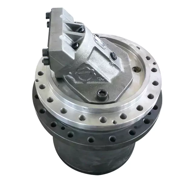
What factors should be considered when selecting the right gear reducer?
Choosing the appropriate gear reducer involves considering several crucial factors to ensure optimal performance and efficiency for your specific application:
- 1. Torque and Power Requirements: Determine the amount of torque and power your machinery needs for its operation.
- 2. Speed Ratio: Calculate the required speed reduction or increase to match the input and output speeds.
- 3. Gear Type: Select the appropriate gear type (helical, bevel, worm, planetary, etc.) based on your application's torque, precision, and efficiency requirements.
- 4. Mounting Options: Consider the available space and the mounting configuration that suits your machinery.
- 5. Environmental Conditions: Evaluate factors such as temperature, humidity, dust, and corrosive elements that may impact the gear reducer's performance.
- 6. Efficiency: Assess the gear reducer's efficiency to minimize power losses and improve overall system performance.
- 7. Backlash: Consider the acceptable level of backlash or play between gear teeth, which can affect precision.
- 8. Maintenance Requirements: Determine the maintenance intervals and procedures necessary for reliable operation.
- 9. Noise and Vibration: Evaluate noise and vibration levels to ensure they meet your machinery's requirements.
- 10. Cost: Compare the initial cost and long-term value of different gear reducer options.
By carefully assessing these factors and consulting with gear reducer manufacturers, engineers and industry professionals can make informed decisions to select the right gear reducer for their specific application, optimizing performance, longevity, and cost-effectiveness.
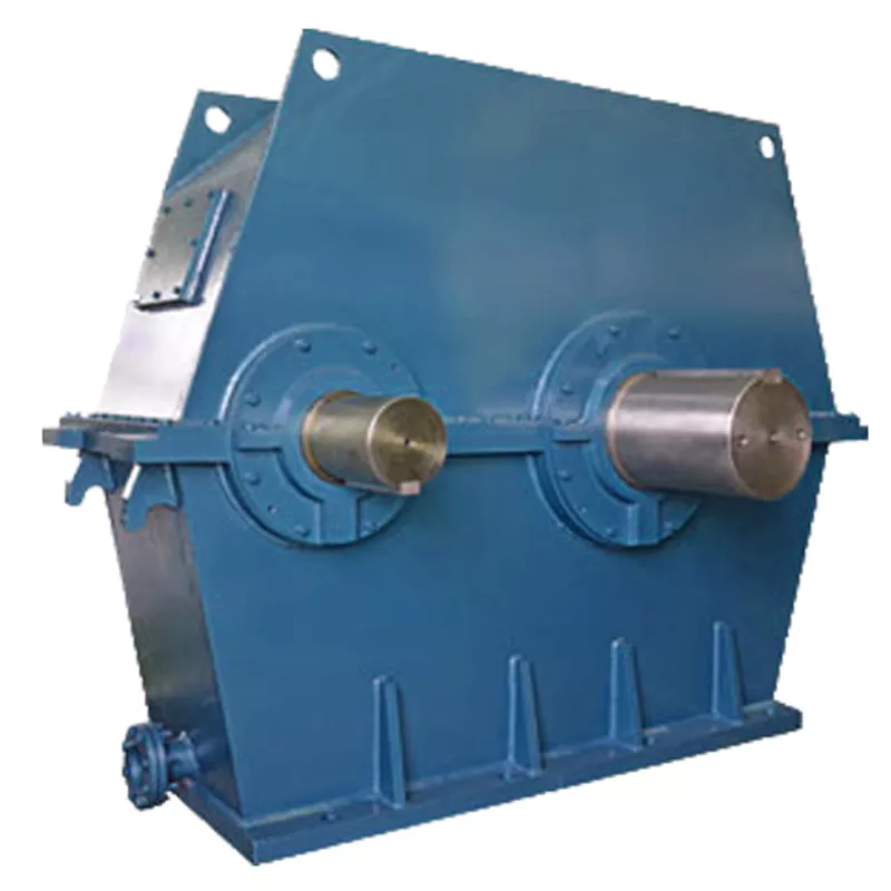
Function of Gear Reducers in Mechanical Systems
A gear reducer, also known as a gear reduction unit or gearbox, is a mechanical device designed to reduce the speed of an input shaft while increasing its torque output. It accomplishes this through the use of a set of interlocking gears with different sizes.
The primary function of a gear reducer in mechanical systems is to:
- Speed Reduction: The gear reducer takes the high-speed rotation of the input shaft and transmits it to the output shaft through a set of gears. The gears are configured in such a way that the output gear has a larger diameter than the input gear. As a result, the output shaft rotates at a lower speed than the input shaft, but with increased torque.
- Torque Increase: Due to the size difference between the input and output gears, the torque applied to the output shaft is greater than that of the input shaft. This torque multiplication allows the system to handle heavier loads and perform tasks requiring higher force.
Gear reducers are widely used in various industries and applications where it's necessary to adapt the speed and torque characteristics of a power source to meet the requirements of the driven equipment. They can be found in machinery such as conveyor systems, industrial machinery, vehicles, and more.


editor by CX 2024-01-31
China high quality High Quality S Series Helical Worm Speed Reducer Gearmotor Gearbox Design for Winch planetary gearbox
Product Description
Detailed Photos
Features of S series reducer
The same model can be equipped with motors of various powers. It is easy to realize the combination and connection between various models.
The transmission efficiency is high, and the single reducer efficiency is up to 96%. three
The transmission ratio is subdivided and the range is wide. The combined model can form a large transmission ratio and low output speed.
The installation forms are various, and can be installed with any foot, B5 flange or B4 flange. The foot mounting reducer has 2 machined foot mounting planes.
Helical gear and worm gear combination, compact structure, large reduction ratio.
Installation mode: foot installation, hollow shaft installation, flange installation, torque arm installation, small flange installation.
Input mode: motor direct connection, motor belt connection or input shaft, connection flange input.
Average efficiency: reduction ratio 7.5-69.39 is 77%; 70.43-288 is 62%; The S/R combination is 57%.
S57 SF57 SA57 SAF57 S series helical worm gear box speed reducer 0.18kw 0.25kw 0.37kw 0.55kw 0.75kw 1.1kw 1.5kw 2.2kw 3kw, max. permissible torque up to 300Nm, transmission ratios from 10.78 to 196.21. Mounting mode: foot mounted, flange mounted, short flange mounted, torque arm mounted. Output shaft: CHINAMFG shaft, hollow shaft (with key, with shrink disc and with involute spline).
S series helical gear worm reducer
Features of products
1. The S series helical gear worm gear motor has a high technological content. It has a helical gear and a worm gear combined with an integrated transmission to improve the torque and efficiency of the machine. This series of products have complete specifications, wide speed range, good versatility, adapt to various installation methods, safe and reliable performance and long life, and have implemented international standards.
2. The uneven surface of the body has the effect of heat dissipation, strong vibration absorption, low temperature rise and low noise.
3. The machine has good sealing performance and strong adaptability to the working environment.
4. The machine has high transmission accuracy, and is especially suitable for working in occasions with frequent starting. It can be connected to various types of reducers and equipped with various types of motor drives, and can be installed in the 90-degree transmission operating position.
5. The key components of the motor are made of highly wear-resistant materials and undergo special heat treatment. They have the characteristics of high machining accuracy, stable transmission, small size, large carrying capacity, and long life.
6. The reducer can be equipped with various types of motors, forming a mechatronics, which fully guarantees the quality characteristics of the product.
|
Gearing Arrangement |
Helical-worm |
|
Output Torque |
10-4484 Nm |
|
Input Speed |
Reference details page |
|
Output Speed |
0.21-12 r/min |
|
Color |
Customizable |
|
Certificate |
ISO9001 |
|
Structure |
SF |
|
Input power rating |
0.55-7.5 |
|
Ratio |
9.96-241.09 |
|
Maximum torque |
1270 |
|
Input Configurations |
Equipped with Electric Motors |
|
Applicable Motors |
Single Phase AC Motor, Three Phase AC Motor |
|
Output Configurations |
Solid Shaft Output |
|
nstallation |
Foot-mounted |
|
Lubrication |
Oil-bath and Splash Lubrication |
Product Description
Product Parameters
For more models, please contact us!
F helical gear reducer
Parallel output, compact structure, large transmission torque, stable operation, low noise and long life.
Installation method: base installation, flange installation, torque arm installation.
Reduction ratio: basic type 2 level 4.3-25.3, 3 level 28.2-273, combined to 18509.
The rotation direction of the input and output of the basic two-stage is the same, and the three-stage is opposite; please consult when combining.
Output mode: hollow shaft output or CHINAMFG shaft output.
Average efficiency: Level 2 96%, Level 3 94%, F/CR average efficiency 85%.
K helical bevel gear reducer
Vertical output, compact structure, hard tooth surface transmission torque, high-precision gears ensure stable work, low noise
and long life.
Installation method: base installation, flange installation, torque arm installation, small flange installation.
Input mode: motor direct connection, motor belt connection or input shaft, connection flange input.
Output mode: hollow shaft output or CHINAMFG shaft output, the average efficiency is 94%.
Reduction ratio: basic type 8.1-191, combined to 13459.
R helical gear reducer
Small bias output, compact structure, maximum use of cabinet space, the second and third levels are in the same cabinet. Using an integral cast box, the box structure has good rigidity, which is easy to improve the strength of the shaft and the life of the
bearing.
Installation method: pedestal installation, flanges with large and small flanges are easy to choose.
Solid shaft output, the average efficiency is 96% in the second stage, 94% in the third stage, and 85% in CR/CR. The CRM series specially designed for mixing can carry large axial and radial forces.
Company Profile
Certifications
Packaging & Shipping
FAQ
| Hardness: | Hardened Tooth Surface |
|---|---|
| Installation: | 90 Degree |
| Layout: | Expansion |
| Gear Shape: | Bevel Gear |
| Step: | Single-Step |
| Type: | Gear Reducer |
| Samples: |
US$ 80/Piece
1 Piece(Min.Order) | |
|---|
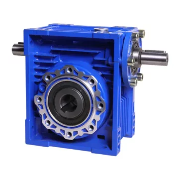
What are the Noise Levels Associated with Worm Gearboxes?
The noise levels associated with worm gearboxes can vary depending on several factors, including the design, quality, operating conditions, and maintenance of the gearbox. Here are some key points to consider:
- Design and Quality: Well-designed and high-quality worm gearboxes tend to produce lower noise levels. Factors such as gear tooth profile, precision manufacturing, and proper alignment can contribute to reduced noise.
- Gear Engagement: The way the worm and worm wheel engage and mesh with each other can impact noise levels. Proper tooth contact and alignment can help minimize noise during operation.
- Lubrication: Inadequate or improper lubrication can lead to increased friction and wear, resulting in higher noise levels. Using the recommended lubricant and maintaining proper lubrication levels are important for noise reduction.
- Operating Conditions: Operating the gearbox within its specified load and speed limits can help prevent excessive noise generation. Overloading or operating at high speeds beyond the gearbox's capabilities can lead to increased noise.
- Backlash: Excessive backlash or play between the gear teeth can lead to impact noise as the teeth engage. Proper backlash adjustment can help mitigate this issue.
- Maintenance: Regular maintenance, including gear inspection, lubrication checks, and addressing any wear or damage, can help keep noise levels in check.
It's important to note that while worm gearboxes can produce some noise due to the nature of gear meshing, proper design, maintenance, and operation can significantly reduce noise levels. If noise is a concern for your application, consulting with gearbox manufacturers and experts can provide insights into selecting the right gearbox type and implementing measures to minimize noise.
How to Calculate the Input and Output Speeds of a Worm Gearbox?
Calculating the input and output speeds of a worm gearbox involves understanding the gear ratio and the principles of gear reduction. Here's how you can calculate these speeds:
- Input Speed: The input speed (N1) is the speed of the driving gear, which is the worm gear in this case. It is usually provided by the manufacturer or can be measured directly.
- Output Speed: The output speed (N2) is the speed of the driven gear, which is the worm wheel. To calculate the output speed, use the formula:
N2 = N1 / (Z1 * i)
Where:
N2 = Output speed (rpm)
N1 = Input speed (rpm)
Z1 = Number of teeth on the worm gear
i = Gear ratio (ratio of the number of teeth on the worm gear to the number of threads on the worm)
It's important to note that worm gearboxes are designed for gear reduction, which means that the output speed is lower than the input speed. Additionally, the efficiency of the gearbox, friction, and other factors can affect the actual output speed. Calculating the input and output speeds is crucial for understanding the performance and capabilities of the worm gearbox in a specific application.
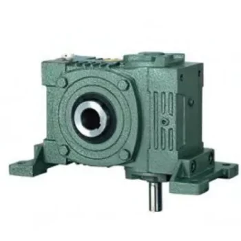
Advantages of Using a Worm Reducer in Mechanical Systems
Worm reducers offer several advantages that make them suitable for various mechanical systems:
- High Gear Reduction Ratio: Worm gearboxes provide significant speed reduction, making them ideal for applications that require a high gear reduction ratio without the need for multiple gears.
- Compact Design: Worm reducers have a compact and space-saving design, allowing them to be used in applications with limited space.
- Self-Locking: Worm gearboxes exhibit self-locking properties, which means that the worm screw can prevent the worm wheel from reversing its motion. This is beneficial for applications where the gearbox needs to hold a load in place without external braking mechanisms.
- Smooth and Quiet Operation: Worm gearboxes operate with a sliding motion between the teeth, resulting in smoother and quieter operation compared to some other types of gearboxes.
- High Torque Transmission: Worm gearboxes can transmit high torque levels, making them suitable for applications that require powerful torque output.
- Heat Dissipation: The sliding action between the worm screw and the worm wheel contributes to heat dissipation, which can be advantageous in applications that generate heat during operation.
- Stable Performance: Worm reducers offer stable and reliable performance, making them suitable for continuous operation in various industrial and mechanical systems.
Despite these advantages, it's important to note that worm gearboxes also have limitations, such as lower efficiency compared to other gear types due to the sliding motion and potential for higher heat generation. Therefore, selecting the appropriate type of gearbox depends on the specific requirements and constraints of the application.


editor by CX 2023-09-18
China Good quality XWD4 power 0.75-4 kw 500 N.m horizontal cycloid gearmotor cycloidal drive reducer near me shop
Relevant Industries: Manufacturing Plant, Machinery Repair Shops, Foodstuff & Beverage Manufacturing facility, Retail, Development works , Energy & Mining
Gearing Arrangement: Cycloidal
Output Torque: up to 20000Nm
Enter Speed: 1400rpm, 1680rpm
Output Speed: .3~140rpm
equipment arrangement: cycloidal
Material of gear: 20CrMnTi with high precision grinding
Content of Housing: cast iron
Substance of shaft: 40Cr with carburizing and quenching
Guarantee: 12months
Input structure: IEC flange, immediate with motor, shaft input
Mounting Placement: Horizontal (foot mounted) or Vertical (flange mounted)
Equipment Ratio: eleven,seventeen,23,29,35,forty three,fifty nine,71, BWD3 BLD3 generate reducer cycloidal gearbox solitary-stage gearbox Speed Reducer 87
OEM services: offered
Application: packing device, foods approach, lift, crane, agitator, feeder
Packaging Specifics: Export Standard picket circumstance, plywooden scenario with pallet
Cycloidal gearboxCycloid reducer is a cycloid needle enamel meshing planetary transmission theory drive designs, is an perfect transmission with numerous advantages:
Houshing:
Casting Iron
Gearset:
Cycloid wheel & Pin wheel
Input Configurations:
Equipped with Electric powered Motors (AC Motor, Brake Motor, Explosion-proof Motor, Regulated Speed Motor, Hydraulic Motor)
IEC-normalized Motor Flange, Keyed Reliable Shaft Enter
Output Configurations:
Keyed Reliable Shaft Output
Characteristic OneEconomic but Higher performance, the regular effectiveness is in excess of ninety%
Feature Two
Large reduction ratio, 1-phase ratio 9~87, High quality timing belt Crankshaft pulley for Hyundai h100 D4BA 23129-42070 42000 42001 42011 2-stage ratio 121~1849, greater reduction ratio is accessible by 3-phase or multistagecombinations.1 Stage Ratio: 9, 11, seventeen, 23, 29, 35, forty three, fifty nine, seventy one, 872 Stage Ratio: 121, 187, 289, 385, 473, 595, Sliding Doorway Hanging Wheel Roller Pulley 608ZZ black nylon roller pa6 with 8x36x12mm 731, 989, 1225, 1849
Feature A few
Lower speed, low frequency: primarily used for hefty load, low pace and no frequent work place1 Stage Ratio: 9, 11, 17, 23, 29, 35, forty three, 59, 71, 87 Connected Products Packing&Delivery Business Introduction
Driveshaft structure and vibrations associated with it
The framework of the push shaft is essential to its performance and reliability. Drive shafts normally include claw couplings, rag joints and universal joints. Other push shafts have prismatic or splined joints. Learn about the different types of drive shafts and how they work. If you want to know the vibrations linked with them, study on. But very first, let's outline what a driveshaft is.
transmission shaft
As the demand from customers on our vehicles proceeds to enhance, so does the demand from customers on our push systems. Larger CO2 emission specifications and stricter emission expectations enhance the stress on the travel system while strengthening ease and comfort and shortening the turning radius. These and other adverse effects can place significant anxiety and put on on elements, which can lead to driveshaft failure and increase motor vehicle protection dangers. Consequently, the push shaft need to be inspected and changed frequently.
Dependent on your design, you may possibly only need to replace a single driveshaft. Nonetheless, the cost to change each driveshafts ranges from $650 to $1850. In addition, you may possibly incur labor charges ranging from $one hundred forty to $250. The labor cost will count on your automobile design and its drivetrain sort. In general, however, the price of replacing a driveshaft ranges from $470 to $1850.
Regionally, the automotive driveshaft market place can be divided into 4 main markets: North The usa, Europe, Asia Pacific, and Relaxation of the Planet. North The united states is anticipated to dominate the industry, whilst Europe and Asia Pacific are envisioned to grow the fastest. In addition, the marketplace is envisioned to expand at the optimum fee in the future, driven by economic progress in the Asia Pacific area. Additionally, most of the vehicles marketed globally are created in these areas.
The most critical feature of the driveshaft is to transfer the power of the motor to useful function. Generate shafts are also identified as propeller shafts and cardan shafts. In a car, a propshaft transfers torque from the engine, transmission, and differential to the front or rear wheels, or equally. Thanks to the complexity of driveshaft assemblies, they are crucial to automobile security. In addition to transmitting torque from the engine, they need to also compensate for deflection, angular changes and size adjustments.
type
Various kinds of drive shafts contain helical shafts, gear shafts, worm shafts, planetary shafts and synchronous shafts. Radial protruding pins on the head offer a rotationally protected relationship. At minimum a single bearing has a groove extending together its circumferential duration that makes it possible for the pin to go by means of the bearing. There can also be two flanges on every conclude of the shaft. Relying on the software, the shaft can be set up in the most hassle-free location to purpose.
Propeller shafts are typically made of higher-good quality steel with high distinct energy and modulus. However, they can also be manufactured from sophisticated composite components this sort of as carbon fiber, Kevlar and fiberglass. An additional sort of propeller shaft is created of thermoplastic polyamide, which is rigid and has a substantial strength-to-fat ratio. Each generate shafts and screw shafts are used to generate automobiles, ships and motorcycles.
Sliding and tubular yokes are typical parts of drive shafts. By style, their angles have to be equal or intersect to supply the correct angle of procedure. Except if the working angles are equal, the shaft vibrates two times for each revolution, triggering torsional vibrations. The greatest way to steer clear of this is to make positive the two yokes are properly aligned. Crucially, these components have the identical functioning angle to make certain sleek electrical power flow.
The sort of push shaft may differ in accordance to the kind of motor. Some are geared, whilst other folks are non-geared. In some cases, the drive shaft is mounted and the motor can rotate and steer. Alternatively, a flexible shaft can be employed to handle the velocity and direction of the drive. In some programs exactly where linear power transmission is not feasible, flexible shafts are a valuable selection. For instance, flexible shafts can be utilised in moveable products.
set up
The development of the generate shaft has numerous positive aspects in excess of bare metal. A shaft that is flexible in multiple instructions is simpler to sustain than a shaft that is rigid in other instructions. The shaft entire body and coupling flange can be created of various resources, and the flange can be manufactured of a diverse material than the primary shaft human body. For illustration, the coupling flange can be produced of steel. The major shaft entire body is if possible flared on at least 1 finish, and the at least 1 coupling flange involves a initial normally frustoconical projection extending into the flared end of the main shaft physique.
The regular stiffness of fiber-based mostly shafts is accomplished by the orientation of parallel fibers alongside the size of the shaft. Even so, the bending stiffness of this shaft is decreased because of to the adjust in fiber orientation. Since the fibers carry on to travel in the exact same course from the 1st stop to the 2nd conclude, the reinforcement that raises the torsional stiffness of the shaft is not influenced. In distinction, a fiber-based shaft is also adaptable since it utilizes ribs that are roughly ninety degrees from the centerline of the shaft.
In addition to the helical ribs, the generate shaft 100 may also contain reinforcing aspects. These reinforcing factors keep the structural integrity of the shaft. These reinforcing aspects are known as helical ribs. They have ribs on each the outer and inner surfaces. This is to prevent shaft breakage. These components can also be shaped to be versatile adequate to accommodate some of the forces produced by the travel. Shafts can be made using these approaches and made into worm-like drive shafts.
vibration
The most frequent cause of drive shaft vibration is improper installation. There are 5 typical types of driveshaft vibration, each and every relevant to installation parameters. To stop this from happening, you ought to comprehend what causes these vibrations and how to correct them. The most widespread varieties of vibration are shown beneath. This article describes some common generate shaft vibration options. It may also be useful to think about the tips of a specialist vibration technician for drive shaft vibration management.
If you might be not sure if the problem is the driveshaft or the motor, attempt turning on the stereo. Thicker carpet kits can also mask vibrations. However, you ought to speak to an expert as quickly as achievable. If vibration persists after vibration-relevant repairs, the driveshaft demands to be replaced. If the driveshaft is even now beneath warranty, you can fix it by yourself.
CV joints are the most typical lead to of third-purchase driveshaft vibration. If they are binding or fail, they need to have to be replaced. Alternatively, your CV joints could just be misaligned. If it is loose, you can verify the CV connector. One more widespread cause of generate shaft vibration is poor assembly. Poor alignment of the yokes on equally finishes of the shaft can result in them to vibrate.
Incorrect trim peak can also cause driveshaft vibration. Right trim peak is necessary to avoid travel shaft wobble. Whether or not your vehicle is new or old, you can complete some basic fixes to reduce issues. 1 of these answers includes balancing the generate shaft. First, use the hose clamps to attach the weights to it. Next, attach an ounce of fat to it and spin it. By carrying out this, you reduce the frequency of vibration.
cost
The global driveshaft marketplace is envisioned to exceed (xxx) million USD by 2028, developing at a compound yearly progress rate (CAGR) of XX%. Its soaring expansion can be attributed to several variables, such as increasing urbanization and R&D investments by leading market place players. The report also consists of an in-depth analysis of key market tendencies and their influence on the industry. Moreover, the report provides a comprehensive regional analysis of the Driveshaft Industry.
The price of changing the generate shaft relies upon on the type of fix required and the result in of the failure. Typical mend fees selection from $300 to $750. Rear-wheel push autos generally value a lot more. But front-wheel push autos expense less than 4-wheel generate cars. You may also select to consider repairing the driveshaft by yourself. Nonetheless, it is critical to do your research and make positive you have the essential equipment and equipment to complete the occupation correctly.
The report also addresses the competitive landscape of the Generate Shafts industry. It involves graphical representations, in depth figures, management policies, and governance parts. Additionally, it consists of a detailed cost analysis. Additionally, the report offers views on the COVID-19 industry and long term developments. The report also provides valuable data to assist you choose how to compete in your industry. When you acquire a report like this, you are incorporating reliability to your function.
A top quality driveshaft can improve your match by ensuring length from the tee and improving responsiveness. The new material in the shaft building is lighter, more robust and far more responsive than ever prior to, so it is getting to be a essential element of the driver. And there are a assortment of alternatives to suit any budget. The primary issue to take into account when getting a shaft is its quality. Even so, it's crucial to be aware that quality isn't going to appear low-cost and you should constantly select an axle primarily based on what your spending budget can deal with.

