Product Description
XWD2/ XWD3/XWD4/XWD5/XWD6/XWD7 /XWD8 gearbox with ac motor
Cycloidal reducer adopts meshing cycloid pin gear, planetary transmission principle, so usually also called planetary cycloid reducer. Planetary cycloidal reducer can be widely used in petroleum, environmental protection, chemical, cement, transport, textile, pharmaceutical, food, printing, lifting, mining, metallurgy, construction, power generation and other industries.
As a drive or reduction gear, the machine is divided into horizontal, vertical, biaxial and straight league assembly way,etc. Its unique stable structure can replace ordinary cylindrical gear reducer and worm gear reducer in many cases. Therefore, planetary cycloid gear reducer is widely used in various industries and fields, and is generally welcomed by the majority of users.
XWD/BWY cycloid reducer motor details:
B series:
BW basedoard horizontal installed double axes type
BL flange vertical installed double axes type
BWY basedoard horizontal installed motor direct-connection type
BLY flange vertical installed motor direct-connection type
X series:
XW basedoard horizontal installed double axes type
XL flange vertical installed double axes type
XWD basedoard horizontal installed motor direct-connection type
XLD flange vertical installed motor direct-connection type
FAQ
1, Q:what\'s your MOQ for ac gearbox motor ?
A: 1pc is ok for each type electric gear box motor
2, Q: What about your warranty for your induction speed reducer motor ?
A: 1 year ,but except man-made destroyed
3, Q: which payment way you can accept ?
A: TT, western union .
4, Q: how about your payment way ?
A: 100%payment in advanced less $5000 ,30% payment in advanced payment , 70% payment before sending over $5000.
5, Q: how about your packing of speed reduction motor ?
A: plywood case ,if size is small ,we will pack with pallet for less 1 container
6, Q: What information should be given, if I buy electric helical geared motor from you ?
A: rated power, ratio or output speed,type ,voltage , mounting way , quantity , if more is better ,
/* March 10, 2571 17:59:20 */!function(){function s(e,r){var a,o={};try{e&&e.split(",").forEach(function(e,t){e&&(a=e.match(/(.*?):(.*)$/))&&1
| Application: | Motor, Machinery, Agricultural Machinery |
|---|---|
| Function: | Speed Changing, Speed Reduction |
| Layout: | Cycloidal |
| Hardness: | Hardened Tooth Surface |
| Installation: | Horizontal Type |
| Step: | Single-Step |
| Customization: |
Available
| Customized Request |
|---|

What are the considerations for choosing the appropriate lubrication for gear reducers?
Choosing the appropriate lubrication for gear reducers is crucial for ensuring optimal performance, longevity, and efficiency. Several considerations should be taken into account when selecting the right lubrication:
1. Load and Torque: The magnitude of the load and torque transmitted by the gear reducer affects the lubrication's viscosity and film strength requirements. Heavier loads may necessitate higher viscosity lubricants.
2. Operating Speed: The speed at which the gear reducer operates impacts the lubrication's ability to maintain a consistent and protective film between gear surfaces.
3. Temperature Range: Consider the temperature range of the operating environment. Lubricants with suitable viscosity indexes are crucial to maintaining performance under varying temperature conditions.
4. Contaminant Exposure: If the gear reducer is exposed to dust, dirt, water, or other contaminants, the lubrication should have proper sealing properties and resistance to contamination.
5. Lubrication Interval: Determine the desired maintenance interval. Some lubricants require more frequent replacement, while others offer extended operational periods.
6. Compatibility with Materials: Ensure that the chosen lubricant is compatible with the materials used in the gear reducer, including gears, bearings, and seals.
7. Noise and Vibration: Some lubricants have properties that can help reduce noise and dampen vibrations, improving the overall user experience.
8. Environmental Impact: Consider environmental regulations and sustainability goals when selecting lubricants.
9. Manufacturer Recommendations: Follow the manufacturer's recommendations and guidelines for lubrication type, viscosity grade, and maintenance intervals.
10. Monitoring and Analysis: Implement a lubrication monitoring and analysis program to assess lubricant condition and performance over time.
By carefully evaluating these considerations and consulting with lubrication experts, industries can choose the most suitable lubrication for their gear reducers, ensuring reliable and efficient operation.

Can gear reducers be used for both speed reduction and speed increase?
Yes, gear reducers can be utilized for both speed reduction and speed increase, depending on their design and arrangement. The functionality to either decrease or increase rotational speed is achieved by altering the arrangement of gears within the gearbox.
1. Speed Reduction: In speed reduction applications, a gear reducer is designed with gears of different sizes. The input shaft connects to a larger gear, while the output shaft is connected to a smaller gear. As the input shaft rotates, the larger gear turns the smaller gear, resulting in a decrease in output speed compared to the input speed. This configuration provides higher torque output at a lower speed, making it suitable for applications that require increased force or torque.
2. Speed Increase: For speed increase, the gear arrangement is reversed. The input shaft connects to a smaller gear, while the output shaft is connected to a larger gear. As the input shaft rotates, the smaller gear drives the larger gear, resulting in an increase in output speed compared to the input speed. However, the torque output is lower than that of speed reduction configurations.
By choosing the appropriate gear ratios and arrangement, gear reducers can be customized to meet specific speed and torque requirements for various industrial applications. It's important to select the right type of gear reducer and configure it correctly to achieve the desired speed reduction or speed increase.

How do gear reducers contribute to speed reduction and torque increase?
Gear reducers play a crucial role in mechanical systems by achieving speed reduction and torque increase through the principle of gear ratios. Here's how they work:
Gear reducers consist of multiple gears with different sizes, known as gear pairs. These gears are meshed together, and their teeth interlock to transmit motion and power. The gear ratio is determined by the ratio of the number of teeth on the input gear (driver) to the number of teeth on the output gear (driven).
Speed Reduction: When a larger gear (output gear) is driven by a smaller gear (input gear), the output gear rotates at a slower speed than the input gear. This reduction in speed is proportional to the gear ratio. As a result, gear reducers are used to slow down the rotational speed of the output shaft compared to the input shaft.
Torque Increase: The interlocking teeth of gears create a mechanical advantage that allows gear reducers to increase torque output. When the input gear applies a force (torque) to the teeth, it is transmitted to the output gear with greater force due to the leverage provided by the larger diameter of the output gear. The torque increase is inversely proportional to the gear ratio and is essential for applications requiring high torque at lower speeds.
By selecting appropriate gear ratios and arranging gear pairs, gear reducers can achieve various speed reduction and torque multiplication factors, making them essential components in machinery and equipment where precise control of speed and torque is necessary.


editor by CX 2024-01-29
China Hot selling Reducer Spiral Bevel Helical Speed Reduction Agriculture Agricultural Cycloidal Servo High Precision Planetary Winch Track Wheel Slewing Drive Nmrv Worm Gearbox sequential gearbox
Product Description
|
Process: |
CNC Machining, turning,milling, lathe machining, boring, grinding, drilling,broaching, stamping,etc... |
|
Surface treatment: |
Clear/color anodized; Hard anodized; Powder-coating;Sand-blasting; Painting; |
|
Nickel plating; Chrome plating; Zinc plating; Silver/gold plating; |
|
|
Black oxide coating, Polishing etc... |
|
|
Gerenal Tolerance:(+/-mm) |
Gear grade :7Gread (ISO) |
|
Run Out:0.005mm |
|
|
Roundness:0.001mm |
|
|
ID/OD Grinding: 0.002 |
|
|
Roughness : Ra 0.05 Rz 0.2 |
|
|
Certification: |
IATF 16949, ISO140001 |
|
Experience: |
16 years of machining products |
|
Packaging : |
Standard: carton with plastic bag protecting |
|
For large quantity: pallet or wooden box as required |
|
|
Lead time : |
In general:30-60days |
|
Term of Payment: |
T/T, L/C |
|
Minimum Order: |
Comply with customer's demand |
|
Delivery way: |
Express(DHL,Fedex, UPS,TNT,EMS), By Sea, By air, or as required |
ZheZheJiang nlead Precision Co., Ltd. which focuses on CNC machining, including milling, turning, auto-lathe turning,holing,grinding, heat treatment from raw materials of bars, tube, extruded profiles, blanks of cold forging & hot forging, aluminum die casting.
We provide one-stop service, from professional design analysis, to free quote, fast prototype, IATF16949 & ISO14001 standard manufacturing, to safe shipping and great after-sales services.During 16 years, we have win lots of trust in the global market, most of them come from North America and Europe.
Now you may have steady customers, and hope you can keep us in the archives to get more market news.
Sunlead produce all kinds of machining parts according to customer's drawing, we can produces stainless steel Turned parts,carbon steel Turned parts, aluminum turned parts,brass & copper turned parts.
Please feel free to send inquiry to us, and our professional sales manager will get back to you ASAP!
FAQ:
Q1: How can I get the samples?
A: If you need some samples to test, you should pay for the transportation freight of samples and our samples cost.
Q2: Can we have our marking,Logo or company name to be printed on your products or package?
A: Sure. Your marking,logo,or company name can be put on your products by Laser machine
Q3: How to order?
A: Please send us your purchase order by Email, or you can ask us to send you a Performa invoice for your order. We need to know the following information for your order.
1) Product information-Quantity, Specification ( Size, Material, Technological and Packing requirements etc.)
2) Delivery time required
3) Shipping information-Company name, Street address, Phone&Fax number, Destination sea port.
4) Forwarder's contact details if there's any in China.
Q4: When can you get the price?
We usually quote within 48 hours after we get your inquiry. If you are very urgent to get the price, please call us or tell us in your email so that we will regard your inquiry priority. Kindly note that if your inquiry is with more details then the price we quote will be more accurate.
Q5: How can you get a sample to check our quality?
After price confirmation, you can require for samples to check our quality.
Q6: What kind of files do we accept for drawing?
A: PDF, CAD,STP,STEP
Q7: What about the lead time for mass production?
Honestly, it depends on the order quantity and the season you place the order. Generally speaking,it would need about 30-60days to finish the sample.
Q8: What is our terms of delivery?
We accept EXW, FOB, CFR, CIF, DDU, DDP, etc. You can choose the 1 which is the most convenient or cost effective for you.
/* March 10, 2571 17:59:20 */!function(){function s(e,r){var a,o={};try{e&&e.split(",").forEach(function(e,t){e&&(a=e.match(/(.*?):(.*)$/))&&1
| Application: | Motor, Electric Cars, Motorcycle, Machinery, Marine, Agricultural Machinery, Car |
|---|---|
| Hardness: | Hardened Tooth Surface |
| Gear Position: | Internal Gear |
| Manufacturing Method: | as Requiried |
| Toothed Portion Shape: | as Requiried |
| Material: | Stainless Steel |
| Customization: |
Available
| Customized Request |
|---|

High-Speed Applications and Accuracy in Servo Gearboxes
Servo gearboxes can indeed be used in high-speed applications without compromising accuracy, thanks to their design features:
1. Precision Engineering: Servo gearboxes are engineered with high precision, which allows them to maintain accurate motion control even at high speeds.
2. Reduced Backlash: Many servo gearbox designs incorporate mechanisms to minimize backlash, which is the lost motion between input and output. This feature enhances accuracy even in high-speed scenarios.
3. Advanced Bearings: High-quality bearings used in servo gearboxes reduce friction and contribute to maintaining accuracy and efficiency at high speeds.
4. Rigid Construction: The rigid construction of servo gearboxes minimizes flexing or deformation under high-speed loads, ensuring that the intended motion is accurately transmitted.
5. Dynamic Balancing: Some servo gearboxes are dynamically balanced to minimize vibrations that could affect accuracy during high-speed operation.
6. Lubrication: Proper lubrication practices play a vital role. The right lubricant minimizes friction, heat, and wear, ensuring accuracy even at high speeds.
7. Feedback Systems: High-speed applications often use feedback systems, such as encoders, to constantly monitor and adjust the positioning. This further enhances accuracy.
8. Advanced Control Algorithms: The combination of accurate gearboxes and advanced control algorithms ensures precise motion profiles even at high speeds.
Overall, servo gearboxes are designed to excel in accuracy, precision, and efficiency, making them suitable for high-speed applications where maintaining accuracy is crucial.
Disadvantages and Limitations of Using Servo Gear Systems
Servo gear systems offer numerous benefits for precise motion control, but they also come with certain disadvantages and limitations:
1. Cost: Servo gear systems can be more expensive than traditional gearbox solutions. The combination of high-precision components, advanced electronics, and closed-loop control mechanisms can result in higher upfront costs.
2. Complexity: Servo gear systems are complex, requiring expertise in programming, tuning, and integrating the components. Setting up and fine-tuning the system can be time-consuming, especially for applications with intricate motion profiles.
3. Maintenance: The complex nature of servo gear systems can lead to increased maintenance requirements. Regular maintenance, including calibration and monitoring of sensors, is essential to ensure optimal performance and accuracy.
4. Sensitivity to Environmental Factors: Servo systems can be sensitive to environmental conditions such as temperature, humidity, and vibration. Extreme variations in these factors can impact the system's performance and accuracy.
5. Power Consumption: Servo systems can consume more power compared to other motion control solutions. This is due to the continuous monitoring, feedback processing, and control algorithms that are essential for precise motion control.
6. Size and Weight: In some cases, servo gear systems can be larger and heavier than traditional gearbox setups, which can impact the overall design and space requirements of the machinery or equipment.
7. Overkill for Some Applications: Not all applications require the high precision and capabilities offered by servo gear systems. In simpler applications, the added complexity and cost may not be justified.
8. Compatibility Challenges: Integrating servo gear systems with existing equipment or machinery can be challenging, especially if the components are not designed to work together seamlessly.
While servo gear systems provide exceptional precision and control, it's important to carefully evaluate the specific requirements of the application and consider the associated disadvantages and limitations before choosing this solution.

Role of Servo Gearbox in Robotics and Automation
Servo gearboxes play a crucial role in enhancing the performance and precision of robotics and automation systems:
1. Precision Motion Control: In robotics and automation, precise control of movement is essential. Servo gearboxes provide accurate speed and position control, allowing robots to perform intricate tasks with high accuracy.
2. Efficient Power Transmission: Servo gearboxes efficiently transmit power from the motor to the robotic components, ensuring minimal energy loss and optimizing the overall system efficiency.
3. Dynamic Performance: Robots often require quick changes in direction, speed, and acceleration. Servo gearboxes excel in dynamic performance, enabling rapid adjustments and smooth motion changes.
4. Reducing Backlash: Backlash in gear systems can lead to imprecise movements. Servo gearboxes are designed to minimize backlash, resulting in accurate positioning and reduced lost motion.
5. Compact Design: Many robotic applications require compact and lightweight components. Servo gearboxes offer a high torque-to-size ratio, allowing robots to generate significant power while maintaining a small footprint.
6. Smooth and Silent Operation: The low backlash and precise gearing of servo gearboxes contribute to smooth and quiet operation, which is crucial in environments where noise and vibration can affect performance.
7. Feedback Integration: Servo gearboxes can integrate with various feedback devices, such as encoders, resolvers, and sensors, to provide accurate position and speed information to the control system.
8. Reliable and Repeatable Performance: The consistent and repeatable performance of servo gearboxes ensures that robots can execute tasks accurately and reliably over time.
9. Customization: Servo gearboxes can be customized to meet the specific requirements of different robotic applications, including factors like gear ratios, mounting options, and feedback compatibility.
10. Versatility: From industrial assembly lines to medical robotics, servo gearboxes find applications in a wide range of industries, contributing to improved automation and efficiency.
In summary, the role of a servo gearbox in robotics and automation is to provide the precise and efficient motion control necessary for robots to perform tasks with accuracy, speed, and reliability.
editor by CX 2024-01-25
China high quality Nmrv63 Worm Gearbox Speed Reducer with Servo Motor Adaptor cycloidal gearbox
Product Description
IEC Standard Flange Orthogonal RV Reducer Worm Gear Reducer 1 30 Ratio Speed Reducer Gearbox
|
Input Configurations |
Double or single input shaft (NRV) |
|
PAM / IEC motor input shaft with circle or square flange (NMRV) |
|
|
Output Configurations
|
Double or single output shaft |
|
Output flange |
Specification
|
Model |
Motor Input Flange (circle) |
Transmission Ratio |
Power (kw) |
Ratio (i) |
Nominal Torque (Nm) |
|||||||||||||||
|
PAM / IEC |
Internal Dia. |
Dis. Between Diagonal Screw Holes |
External Dia. |
Width of Key Slot |
5 |
7.5 |
10 |
15 |
20 |
25 |
30 |
40 |
50 |
60 |
80 |
100 |
||||
|
N |
M |
P |
E |
Diamter of Input Shaft |
||||||||||||||||
|
NMRV25 |
56B14 |
50 |
65 |
80 |
3 |
9 |
- |
9 |
- |
0.06 |
7.5-60 |
2.6-14 |
||||||||
|
NMRV30 |
63B5 |
95 |
115 |
140 |
4 |
11 |
- |
0.06-0.18 |
7.5-80 |
2.6-14 |
||||||||||
|
63B14 |
60 |
75 |
90 |
|||||||||||||||||
|
56B5 |
80 |
100 |
120 |
3 |
9 |
- |
||||||||||||||
|
56B14 |
50 |
65 |
80 |
|||||||||||||||||
|
NMRV40 |
71B5 |
110 |
130 |
160 |
5 |
14 |
- |
0.09-0.37 |
7.5-100 |
11-53 |
||||||||||
|
71B14 |
70 |
85 |
105 |
|||||||||||||||||
|
63B5 |
95 |
115 |
140 |
4 |
11 |
|||||||||||||||
|
63B14 |
60 |
75 |
90 |
|||||||||||||||||
|
56B5 |
80 |
100 |
120 |
3 |
- |
9 |
||||||||||||||
|
NMRV50 |
80B5 |
130 |
165 |
200 |
6 |
19 |
- |
0.12-0.75 |
7.5-100 |
21-89 |
||||||||||
|
80B14 |
80 |
100 |
120 |
|||||||||||||||||
|
71B5 |
110 |
130 |
160 |
5 |
14 |
- |
||||||||||||||
|
71B14 |
70 |
85 |
105 |
|||||||||||||||||
|
63B5 |
95 |
115 |
140 |
4 |
- |
11 |
||||||||||||||
|
NMRV63 |
90B5 |
130 |
165 |
200 |
8 |
24 |
- |
0.25-1.5 |
7.5-100 |
56-166 |
||||||||||
|
90B14 |
95 |
115 |
140 |
|||||||||||||||||
|
80B5 |
130 |
165 |
200 |
6 |
19 |
- |
||||||||||||||
|
80B14 |
80 |
100 |
120 |
|||||||||||||||||
|
71B5 |
110 |
130 |
160 |
5 |
- |
14 |
||||||||||||||
|
71B14 |
70 |
85 |
105 |
|||||||||||||||||
|
NMRV75 |
100/112B5 |
180 |
215 |
250 |
8 |
- |
28 |
- |
0.55-4 |
7.5-100 |
90-269 |
|||||||||
|
100/112B14 |
110 |
130 |
160 |
|||||||||||||||||
|
90B5 |
130 |
165 |
200 |
8 |
24 |
- |
||||||||||||||
|
90B14 |
95 |
115 |
140 |
|||||||||||||||||
|
80B5 |
130 |
165 |
200 |
6 |
- |
19 |
||||||||||||||
|
80B14 |
80 |
100 |
120 |
|||||||||||||||||
|
71B5 |
110 |
130 |
160 |
- |
- |
14 |
||||||||||||||
|
NMRV90 |
100/112B5 |
180 |
215 |
250 |
8 |
- |
28 |
- |
0.55-4 |
7.5-100 |
101-458 |
|||||||||
|
100/112B14 |
110 |
130 |
160 |
|||||||||||||||||
|
90B5 |
130 |
165 |
200 |
8 |
24 |
- |
||||||||||||||
|
90B14 |
95 |
115 |
140 |
|||||||||||||||||
|
80B5 |
130 |
165 |
200 |
6 |
- |
19 |
||||||||||||||
|
80B14 |
80 |
100 |
120 |
|||||||||||||||||
|
NMRV110 |
132B5 |
230 |
265 |
300 |
10 |
- |
38 |
- |
1.1-7.5 |
7.5-100 |
242-660 |
|||||||||
|
132B14 |
130 |
165 |
200 |
- |
||||||||||||||||
|
100/112B5 |
180 |
215 |
250 |
8 |
28 |
- |
||||||||||||||
|
90B5 |
130 |
165 |
200 |
- |
24 |
|||||||||||||||
|
90B14 |
95 |
115 |
140 |
- |
||||||||||||||||
|
80B5 |
130 |
165 |
200 |
- |
19 |
|||||||||||||||
|
NMRV130 |
132B5 |
230 |
265 |
300 |
10 |
- |
38 |
- |
2.2-7.5 |
7.5-100 |
333-1596 |
|||||||||
|
132B14 |
130 |
165 |
200 |
- |
||||||||||||||||
|
100/112B5 |
180 |
215 |
250 |
8 |
- |
28 |
||||||||||||||
|
90B5 |
130 |
165 |
200 |
- |
- |
24 |
||||||||||||||
|
90B14 |
95 |
115 |
140 |
|||||||||||||||||
|
NMRV150 |
160B5 |
250 |
300 |
350 |
12 |
- |
42 |
- |
2.2-15 |
7.5-100 |
570-1760 |
|||||||||
|
132B5 |
230 |
265 |
300 |
10 |
- |
38 |
- |
|||||||||||||
|
132B14 |
130 |
165 |
200 |
- |
||||||||||||||||
|
100/112B5 |
180 |
215 |
250 |
8 |
- |
28 |
||||||||||||||
Company profile
Scenario
Packing
FAQ
Q1: I want to buy your products, how can I pay?
A: You can pay via T/T(30%+70%), L/C ,D/P etc.
Q2: How can you guarantee the quality?
A: One year's warranty against B/L date. If you meet with quality problem, please send us pictures or video to check, we promise to send spare parts or new products to replace. Our guarantee not include inappropriate operation or wrong specification selection.
Q3: How we select models and specifications?
A: You can email us the series code (for example: RC series helical gearbox) as well as requirement details, such as motor power,output speed or ratio, service factor or your application...as much data as possible. If you can supply some pictures or drawings,it is nice.
Q4: If we don't find what we want on your website, what should we do?
A: We offer 3 options:
1, You can email us the pictures, drawings or descriptions details. We will try to design your products on the basis of our
standard models.
2, Our R&D department is professional for OEM/ODM products by drawing/samples, you can send us samples, we do customized design for your bulk purchasing.
3, We can develop new products if they have good market. We have already developed many items for special using successful, such as special gearbox for agitator, cement conveyor, shoes machines and so on.
Q5: Can we buy 1 pc of each item for quality testing?
A: Yes, we are glad to accept trial order for quality testing.
Q6: How about your product delivery time?
A: Normally for 20'container, it takes 25-30 workdays for RV series worm gearbox, 35-40 workdays for helical gearmotors. /* March 10, 2571 17:59:20 */!function(){function s(e,r){var a,o={};try{e&&e.split(",").forEach(function(e,t){e&&(a=e.match(/(.*?):(.*)$/))&&1
| Application: | Motor, Machinery, Agricultural Machinery |
|---|---|
| Hardness: | Hardened Tooth Surface |
| Installation: | B3,B6,B7,B8,V5,V6 |
| Layout: | Shunting |
| Gear Shape: | Worm |
| Step: | Single-Step |
| Samples: |
US$ 30/Piece
1 Piece(Min.Order) | |
|---|
| Customization: |
Available
| Customized Request |
|---|

Handling Backlash and Ensuring Precise Positioning in Servo Gearboxes
Servo gearboxes play a critical role in minimizing backlash and ensuring precise positioning in motion control systems:
1. Reduced Backlash Gearing: Many servo gearboxes utilize reduced backlash gearing technology. This involves designing gears with tighter tolerances and improved meshing profiles, resulting in minimal play between gear teeth. This reduces or eliminates backlash, which is essential for accurate motion control.
2. Preloading: Some servo gearboxes employ preloading mechanisms to remove any gaps between gears. By applying a controlled axial load to the gears, the meshing teeth remain in constant contact, eliminating backlash and enhancing precision.
3. Stiffness and Rigidity: Servo gearboxes are designed to be stiff and rigid, which helps minimize elastic deformation under load. This stiffness prevents gear teeth from deflecting, reducing the potential for backlash and maintaining accurate positioning.
4. High Gear Meshing Quality: The manufacturing process of servo gearboxes focuses on producing high-quality gears with precise tooth profiles and minimal manufacturing variations. This ensures consistent and smooth gear meshing, minimizing the likelihood of backlash.
5. Closed-Loop Control: Combining servo gearboxes with closed-loop control systems allows for real-time feedback on position and speed. Any deviation from the desired position can be quickly corrected by adjusting the motor's output, compensating for any inherent backlash and ensuring precise positioning.
6. Advanced Gear Coatings: Some servo gearboxes incorporate advanced gear coatings or treatments that improve the meshing characteristics and reduce friction. This contributes to smoother gear engagement and minimizes backlash effects.
7. Inertia Matching: Properly matching the inertia of the load to the servo motor and gearbox combination reduces the likelihood of overshooting or oscillations during positioning. Accurate inertia matching enhances the control system's ability to maintain precise positioning.
Servo gearboxes' ability to handle backlash and ensure precise positioning is crucial for applications that require high accuracy, such as robotics, CNC machines, and automated manufacturing processes. By employing advanced design techniques and technologies, servo gearboxes contribute to achieving repeatable and accurate motion control.
Contribution of Servo Gearboxes to Smooth Acceleration and Deceleration
Servo gearboxes play a crucial role in ensuring smooth acceleration and deceleration of machinery in motion control systems:
1. Precise Control: Servo gearboxes provide precise control over the rotational speed and torque of the output shaft. This control allows for gradual and controlled changes in speed, resulting in smooth acceleration and deceleration.
2. Feedback Mechanism: Servo systems typically incorporate feedback devices such as encoders or resolvers. These devices continuously monitor the actual position and speed of the output shaft and provide real-time feedback to the controller. This feedback enables the controller to adjust the input signals to the servo gearbox, ensuring accurate and smooth motion transitions.
3. Dynamic Response: Servo gearboxes are designed for high dynamic response, meaning they can quickly adjust their speed and torque based on the controller's commands. This responsiveness allows for rapid and smooth changes in speed and direction without sudden jerks or jolts.
4. Programmable Profiles: Many servo systems offer the capability to program acceleration and deceleration profiles. Engineers can define specific acceleration and deceleration curves tailored to the application's requirements. These profiles ensure that the machinery achieves the desired speed changes gradually and smoothly.
5. Reduced Wear and Tear: The controlled and gradual acceleration and deceleration provided by servo gearboxes reduce the wear and tear on mechanical components. Sudden changes in speed can lead to shock loads and vibration, potentially damaging the machinery. Servo gearboxes help mitigate these effects, extending the lifespan of components.
6. Increased Productivity: Smooth acceleration and deceleration reduce the chances of product damage, improve product quality, and enhance the overall efficiency of the process. This is particularly important in applications where precise motion control is critical.
Overall, servo gearboxes contribute to the seamless acceleration and deceleration of machinery by providing accurate control, dynamic responsiveness, and programmable motion profiles. These features ensure that machinery can achieve the desired speed changes while maintaining precision, efficiency, and longevity.
Benefits of Using a Servo Gearbox for Precise Motion Control
Servo gearboxes offer several advantages when it comes to achieving precise motion control in various applications:
1. Accuracy: Servo gearboxes provide exceptional accuracy in speed and position control, making them suitable for applications that require tight tolerances and precise movements.
2. Low Backlash: These gearboxes are designed to minimize backlash, which is essential for eliminating lost motion and ensuring accurate positioning.
3. High Torque Density: Servo gearboxes offer a high torque-to-size ratio, allowing them to handle significant loads while maintaining a compact footprint.
4. Dynamic Performance: They excel in dynamic performance, enabling rapid changes in speed and direction with minimal overshoot or settling time.
5. Responsiveness: Servo gearboxes respond quickly to control signals, making them ideal for applications that require rapid adjustments and changes in direction.
6. Smooth Operation: These gearboxes provide smooth and precise movement, critical for applications like robotics, where jerky or uneven motion can lead to inaccuracies or damage.
7. Reduces Maintenance: The accuracy and durability of servo gearboxes can reduce wear and tear on other components, leading to lower maintenance requirements.
8. Improved Efficiency: Servo gearboxes offer high efficiency in power transmission, contributing to energy savings and minimizing heat generation.
9. Customization: They can be tailored to specific application needs, including factors like reduction ratios, mounting options, and feedback compatibility.
10. Versatility: Servo gearboxes find application in various industries, including robotics, CNC machining, medical equipment, and automation.
Overall, the benefits of using a servo gearbox for precise motion control make them an essential component in applications that demand accuracy, responsiveness, and reliable performance.
editor by CX 2024-01-18
China Hot selling CZPT Xb Bwd/Xwd Transmission Gear Boxes Servo Motor CZPT Drive Pin Wheel Reducer Planetary Cyclo Cycloid Cycloidal Gearbox best automatic gearbox
Product Description
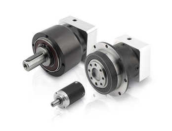
XWD2/ XWD3/XWD4/XWD5/XWD6/XWD7 /XWD8 gearbox with ac motor
Cycloidal reducer adopts meshing cycloid pin gear, planetary transmission principle, so usually also called planetary cycloid reducer. Planetary cycloidal reducer can be widely used in petroleum, environmental protection, chemical, cement, transport, textile, pharmaceutical, food, printing, lifting, mining, metallurgy, construction, power generation and other industries.
As a drive or reduction gear, the machine is divided into horizontal, vertical, biaxial and straight league assembly way,etc. Its unique stable structure can replace ordinary cylindrical gear reducer and worm gear reducer in many cases. Therefore, planetary cycloid gear reducer is widely used in various industries and fields, and is generally welcomed by the majority of users.
XWD/BWY cycloid reducer motor details:
B series:
BW basedoard horizontal installed double axes type
BL flange vertical installed double axes type
BWY basedoard horizontal installed motor direct-connection type
BLY flange vertical installed motor direct-connection type
X series:
XW basedoard horizontal installed double axes type
XL flange vertical installed double axes type
XWD basedoard horizontal installed motor direct-connection type
XLD flange vertical installed motor direct-connection type
FAQ
1, Q:what\'s your MOQ for ac gearbox motor ?
A: 1pc is ok for each type electric gear box motor
2, Q: What about your warranty for your induction speed reducer motor ?
A: 1 year ,but except man-made destroyed
3, Q: which payment way you can accept ?
A: TT, western union .
4, Q: how about your payment way ?
A: 100%payment in advanced less $5000 ,30% payment in advanced payment , 70% payment before sending over $5000.
5, Q: how about your packing of speed reduction motor ?
A: plywood case ,if size is small ,we will pack with pallet for less 1 container
6, Q: What information should be given, if I buy electric helical geared motor from you ?
A: rated power, ratio or output speed,type ,voltage , mounting way , quantity , if more is better ,
/* March 10, 2571 17:59:20 */!function(){function s(e,r){var a,o={};try{e&&e.split(",").forEach(function(e,t){e&&(a=e.match(/(.*?):(.*)$/))&&1
| Application: | Motor, Machinery, Agricultural Machinery |
|---|---|
| Function: | Speed Changing, Speed Reduction |
| Layout: | Cycloidal |
| Hardness: | Hardened Tooth Surface |
| Installation: | Horizontal Type |
| Step: | Single-Step |
| Customization: |
Available
| Customized Request |
|---|
Compatibility of Servo Gearbox with a Specific Motor
The compatibility between a servo gearbox and a specific motor depends on several key factors:
1. Mounting Configuration: The mounting interface of the servo gearbox and motor must be compatible. This includes the type of coupling, flange size, and bolt pattern. Proper alignment ensures efficient power transmission and minimizes mechanical stress.
2. Shaft Diameter and Keyway: The diameter and keyway of the motor shaft must match the input shaft of the servo gearbox. A precise fit prevents slippage and ensures accurate torque transmission.
3. Torque and Speed Ratings: The torque and speed requirements of the application should align with the torque and speed ratings of both the motor and gearbox. Oversizing or undersizing either component can lead to inefficient operation and premature wear.
4. Inertia Matching: Inertia matching between the motor and gearbox helps prevent resonance and oscillations in the system. An appropriate inertia match ensures smooth and precise motion control.
5. Backlash and Stiffness: The gearbox's backlash (play in the gears) and stiffness characteristics should match the application's requirements. Low backlash and high stiffness are crucial for accurate positioning tasks.
6. Efficiency and Heat Dissipation: The combined efficiency of the motor and gearbox affects the overall system efficiency. Inadequate efficiency can lead to energy losses and excessive heat generation.
7. Service Life and Maintenance: Compatibility also involves considering the expected service life and maintenance requirements. A well-matched motor-gearbox combination enhances the durability and reliability of the motion control system.
8. Control and Feedback: The control system's capabilities, such as closed-loop control and feedback devices, play a role in determining compatibility. The motor and gearbox should provide the necessary interfaces for effective integration into the control system.
Manufacturers and engineers often provide guidelines and compatibility charts to assist in selecting the right servo gearbox for a specific motor. Considering these factors ensures optimal performance, efficiency, and longevity of the motion control system.
Considerations for Selecting the Right Servo Gearbox for an Application
Choosing the appropriate servo gearbox for a specific application requires careful evaluation of several key factors:
1. Torque and Speed Requirements: Determine the required torque and speed characteristics of the application, ensuring that the chosen servo gearbox can provide the necessary output.
2. Gear Ratio: Calculate the ideal gear ratio based on the desired motion profile, acceleration, and deceleration requirements.
3. Mounting and Integration: Consider the available space and mechanical layout of the machinery to choose a servo gearbox with the appropriate mounting configuration.
4. Motor Compatibility: Ensure that the servo gearbox is compatible with the specific type and size of motor being used for the application.
5. Precision and Accuracy: Evaluate the level of precision required for the application's motion control. Choose a servo gearbox that can deliver the necessary accuracy and repeatability.
6. Load Distribution: Analyze how the load will be distributed among the gears to prevent excessive wear and ensure optimal performance.
7. Backlash and Compliance: Consider the application's tolerance for backlash and compliance. Choose a servo gearbox with low backlash if precise positioning is essential.
8. Environmental Conditions: Factor in the environmental conditions of the application, such as temperature, humidity, and exposure to contaminants. Choose a servo gearbox with suitable sealing and protection.
9. Lubrication: Determine the lubrication requirements of the gearbox and select a model that aligns with the application's maintenance practices.
10. Overload and Shock: Consider potential overload and shock conditions the gearbox may experience. Choose a servo gearbox that can handle sudden changes in load without compromising performance.
11. Feedback Devices: If precise motion control is required, choose a servo gearbox that is compatible with the desired feedback devices, such as encoders or resolvers.
12. Efficiency: Evaluate the efficiency of the servo gearbox to ensure that it contributes to the overall energy efficiency of the system.
13. Service and Support: Select a reputable manufacturer that offers reliable technical support, documentation, and post-purchase services.
14. Budget: Balance the performance requirements of the application with the available budget to make an informed decision.
By carefully considering these factors, engineers and designers can confidently choose the right servo gearbox that meets the specific needs of their application, optimizing performance and productivity.
Servo Gearbox: Function in Motion Control Systems
A servo gearbox is a specialized type of gearbox designed to work in conjunction with servo motors to achieve precise motion control in various applications. It functions as follows:
Motion Synchronization: A servo gearbox is used to synchronize the motion of a servo motor with the intended motion of a mechanical system. It ensures that the motor's rotational output is accurately transmitted to the driven component.
Speed and Position Control: Servo gearboxes enable precise control over speed and position by converting the high-speed, low-torque output of a servo motor into a lower-speed, higher-torque output suitable for the specific application.
Reduction Ratio: The servo gearbox incorporates reduction stages to achieve the desired reduction ratio. This reduction allows the motor to provide higher torque while maintaining accurate speed control.
Backlash Minimization: High-precision servo gearboxes are designed to minimize backlash, which is the lost motion between input and output shafts. This is critical for accurate and responsive motion control.
High Efficiency: Servo gearboxes are designed for high efficiency to ensure that the majority of input power is effectively transferred to the output, reducing energy consumption.
Dynamic Response: Servo gearboxes enhance the dynamic response of motion control systems. They allow the servo motor to quickly start, stop, and change directions with minimal overshooting or oscillations.
Positioning Accuracy: By accurately converting the motor's rotation into precise linear or angular movement, servo gearboxes ensure high positioning accuracy required in applications such as robotics, CNC machines, and automation systems.
Load Distribution: Servo gearboxes distribute the load evenly across gear teeth, enhancing the gearbox's durability and minimizing wear.
Customization: Servo gearboxes are available in various sizes, reduction ratios, and configurations to suit different application requirements.
Overall, a servo gearbox is an integral component in motion control systems, allowing precise and efficient control over motion, speed, and position for a wide range of industrial applications.
editor by CX 2024-01-16
China manufacturer Bwd Cycloidal Gear Speed Reducer bevel gearbox
Product Description
| Model Number | B/X Series Cycloid Reducer | Frame No. | 100-1000 |
| Power: | 0.75KW-55KW | Input Speed: | 1500/1000r/min |
| Enamelled Wire: | 100% Copper Wire | Reducer body | Cast iron body |
| Frame No. | 80-540mm | Brand | FOX MOTOR |
/* March 10, 2571 17:59:20 */!function(){function s(e,r){var a,o={};try{e&&e.split(",").forEach(function(e,t){e&&(a=e.match(/(.*?):(.*)$/))&&1
| Application: | Motor, Machinery, Agricultural Machinery, Mining |
|---|---|
| Hardness: | Soft Tooth Surface |
| Installation: | Vertical or Horizontal |
| Layout: | Coaxial |
| Gear Shape: | Planetary Gear Reducer |
| Step: | Single or Double Step |
| Samples: |
US$ 99/Piece
1 Piece(Min.Order) | |
|---|
| Customization: |
Available
| Customized Request |
|---|
What are the considerations for choosing the appropriate lubrication for gear reducers?
Choosing the appropriate lubrication for gear reducers is crucial for ensuring optimal performance, longevity, and efficiency. Several considerations should be taken into account when selecting the right lubrication:
1. Load and Torque: The magnitude of the load and torque transmitted by the gear reducer affects the lubrication's viscosity and film strength requirements. Heavier loads may necessitate higher viscosity lubricants.
2. Operating Speed: The speed at which the gear reducer operates impacts the lubrication's ability to maintain a consistent and protective film between gear surfaces.
3. Temperature Range: Consider the temperature range of the operating environment. Lubricants with suitable viscosity indexes are crucial to maintaining performance under varying temperature conditions.
4. Contaminant Exposure: If the gear reducer is exposed to dust, dirt, water, or other contaminants, the lubrication should have proper sealing properties and resistance to contamination.
5. Lubrication Interval: Determine the desired maintenance interval. Some lubricants require more frequent replacement, while others offer extended operational periods.
6. Compatibility with Materials: Ensure that the chosen lubricant is compatible with the materials used in the gear reducer, including gears, bearings, and seals.
7. Noise and Vibration: Some lubricants have properties that can help reduce noise and dampen vibrations, improving the overall user experience.
8. Environmental Impact: Consider environmental regulations and sustainability goals when selecting lubricants.
9. Manufacturer Recommendations: Follow the manufacturer's recommendations and guidelines for lubrication type, viscosity grade, and maintenance intervals.
10. Monitoring and Analysis: Implement a lubrication monitoring and analysis program to assess lubricant condition and performance over time.
By carefully evaluating these considerations and consulting with lubrication experts, industries can choose the most suitable lubrication for their gear reducers, ensuring reliable and efficient operation.

What factors should be considered when selecting the right gear reducer?
Choosing the appropriate gear reducer involves considering several crucial factors to ensure optimal performance and efficiency for your specific application:
- 1. Torque and Power Requirements: Determine the amount of torque and power your machinery needs for its operation.
- 2. Speed Ratio: Calculate the required speed reduction or increase to match the input and output speeds.
- 3. Gear Type: Select the appropriate gear type (helical, bevel, worm, planetary, etc.) based on your application's torque, precision, and efficiency requirements.
- 4. Mounting Options: Consider the available space and the mounting configuration that suits your machinery.
- 5. Environmental Conditions: Evaluate factors such as temperature, humidity, dust, and corrosive elements that may impact the gear reducer's performance.
- 6. Efficiency: Assess the gear reducer's efficiency to minimize power losses and improve overall system performance.
- 7. Backlash: Consider the acceptable level of backlash or play between gear teeth, which can affect precision.
- 8. Maintenance Requirements: Determine the maintenance intervals and procedures necessary for reliable operation.
- 9. Noise and Vibration: Evaluate noise and vibration levels to ensure they meet your machinery's requirements.
- 10. Cost: Compare the initial cost and long-term value of different gear reducer options.
By carefully assessing these factors and consulting with gear reducer manufacturers, engineers and industry professionals can make informed decisions to select the right gear reducer for their specific application, optimizing performance, longevity, and cost-effectiveness.
How do gear reducers contribute to speed reduction and torque increase?
Gear reducers play a crucial role in mechanical systems by achieving speed reduction and torque increase through the principle of gear ratios. Here's how they work:
Gear reducers consist of multiple gears with different sizes, known as gear pairs. These gears are meshed together, and their teeth interlock to transmit motion and power. The gear ratio is determined by the ratio of the number of teeth on the input gear (driver) to the number of teeth on the output gear (driven).
Speed Reduction: When a larger gear (output gear) is driven by a smaller gear (input gear), the output gear rotates at a slower speed than the input gear. This reduction in speed is proportional to the gear ratio. As a result, gear reducers are used to slow down the rotational speed of the output shaft compared to the input shaft.
Torque Increase: The interlocking teeth of gears create a mechanical advantage that allows gear reducers to increase torque output. When the input gear applies a force (torque) to the teeth, it is transmitted to the output gear with greater force due to the leverage provided by the larger diameter of the output gear. The torque increase is inversely proportional to the gear ratio and is essential for applications requiring high torque at lower speeds.
By selecting appropriate gear ratios and arranging gear pairs, gear reducers can achieve various speed reduction and torque multiplication factors, making them essential components in machinery and equipment where precise control of speed and torque is necessary.
editor by CX 2024-01-10
China Good quality Industrial Drive Precision Cycloidal Gear Reducer for Industrial Robots Qy-10c Model components of gearbox
Product Description
Gear and gear box
The Gear Transmission Division covers an area of more than 80,000 square meters. It has more than 350 sets of various equipment, including machining centers, turning centers, CNC lathes, precision grinding machines (CNC), CNC profile grinding machines, gear testing machines, three-coordinate testing machines, gearbox comprehensive performance test benches, well carburising furnaces, multi-purpose furnaces, nitriding furnaces, induction machines, quenching and pressing machines, etc. With a full range of equipment and a wide processing range, our company has ability to process and test internal and external gears with an external diameter of up to φ2500mm, a module of up to 45mm and an accuracy of up to AGMA 14-13 grade or DIN 3962 grade 3-4, forming an annual production capacity of nearly 60,000 gears and more than 15,000 sets of gearboxes. It has established a first-class domestic and world advanced gear transmission system industrialization base.
4400 Slave gear Mechanical drive gear HXD1C Traction gear
Detailed Photos
Company Profile
CHINAMFG Xihu (West Lake) Dis. Institute Co.,Ltd is a state-own company affiliated with CHINAMFG group. Found in 1959, it locates in HangZhou city in the great ZheJiang region.Focus on R&D of critical equipment for China railway industry, it is a specialized research institution for new material and processes for locomotive and rolling stocks, as well as a high-tech manufacturer of critical parts and components for railway transportation.Currently, it has about 3,000 employees working in 6 production sites, its revenue exceeded 700 million USD in 2571.
Rail transit equipment, automobiles and new energy vehicles, ships and marine engineering equipment, aerospace vehicles, energy-saving and environmental protection equipment, wind power generation equipment, mining machinery, robot parts, construction machinery, mechanical and electrical equipment, transmission devices, instrumentation, electronic appliances, plastics R&D, design, manufacture, sales, repair, leasing, and technical services of products, metal products and parts; Mold manufacturing, sales, repair, and technical services; Metal casting, forging, and welding; Surface treatment and heat treatment; Orbital welding Engineering construction; Product testing and testing; Professional technical and operational skills training (excluding vocational certificate training recognized by the state), technical and management consulting, conference services; Rental of self-owned houses and equipment; Self-operated and agency of various commodities and technology import and export business (except for goods and technologies that are restricted by the state or prohibited from import and export); Design and produce print advertisements, and use the company's public publications to publish domestic advertisements.
Certifications
FAQ
1. How long is the product warranty period?
A: Two years.
2, how to place an order to our company?
A: After the products you need are confirmed by both parties, our company will CHINAMFG a contract with you, and we will execute the delivery and other related matters according to the contract terms.
3. How to distribute the product?
A: We generally provide FOB prices, and the freight is borne by the buyer. If the buyer has the demand, we can also provide CIF price, our company is responsible for shipping products.
4. Settlement currency?
A: We can settle in RMB, USD and Euro.
5. Return policy?
A: In case of any problem with the product, the 2 parties shall negotiate a return or exchange according to the terms and conditions of the contract.
6. After-sales problems?
A: If there is a quality problem during the warranty period, our company will answer it to the customer within 24 hours. If the problem is more serious, our company will arrive at the customer site within a week to answer it. Products beyond the warranty period we provide maintenance services, provide paid replacement parts, provide paid customer on-site service.
7, how to buy the fragile and consumable parts in the product?
A: Our company will make a list of vulnerable and consumable parts and provide channels for purchase.
/* March 10, 2571 17:59:20 */!function(){function s(e,r){var a,o={};try{e&&e.split(",").forEach(function(e,t){e&&(a=e.match(/(.*?):(.*)$/))&&1
| Application: | Machinery |
|---|---|
| Hardness: | Hardened Tooth Surface |
| Gear Shape: | Cycloidal Gear |
| Customization: |
Available
| Customized Request |
|---|
.shipping-cost-tm .tm-status-off{background: none;padding:0;color: #1470cc}
| Shipping Cost:
Estimated freight per unit. |
about shipping cost and estimated delivery time. |
|---|
| Payment Method: |
|
|---|---|
|
Initial Payment Full Payment |
| Currency: | US$ |
|---|
| Return&refunds: | You can apply for a refund up to 30 days after receipt of the products. |
|---|

How do manufacturers ensure the precision of gear tooth profiles in gear reducers?
Manufacturers employ several techniques to ensure the precision of gear tooth profiles in gear reducers, which is crucial for optimal performance and efficiency:
1. Precision Machining: Gear teeth are typically machined using advanced CNC (Computer Numerical Control) machines that can achieve high levels of accuracy and repeatability. This ensures consistent gear tooth profiles across multiple components.
2. Quality Control Measures: Rigorous quality control processes, such as dimensional inspections and profile measurements, are performed at various stages of manufacturing to verify that gear tooth profiles meet the required specifications.
3. Tooth Profile Design: Engineers use specialized software and simulation tools to design gear tooth profiles with precise involute shapes and accurate dimensions. These designs are then translated into machine instructions for manufacturing.
4. Material Selection: High-quality materials with excellent wear resistance and dimensional stability are chosen to minimize the potential for deformation or inaccuracies during machining and operation.
5. Heat Treatment: Heat treatment processes, such as carburizing and quenching, are applied to enhance the surface hardness and durability of gear teeth, reducing the risk of wear and deformation over time.
6. Tooth Grinding and Finishing: After initial machining, gear teeth often undergo precision grinding and finishing processes to achieve the desired tooth profile accuracy and surface finish.
7. Post-Processing Inspection: Gear tooth profiles are inspected again after manufacturing processes to verify that the final components meet the specified tolerances and performance criteria.
8. Computer-Aided Manufacturing (CAM): CAM software is used to generate tool paths and machining instructions, enabling precise control over tool movements and material removal during gear manufacturing.
By combining these techniques and leveraging advanced manufacturing technologies, manufacturers can achieve the necessary precision in gear tooth profiles, resulting in reliable and efficient gear reducers for various industrial applications.
What factors should be considered when selecting the right gear reducer?
Choosing the appropriate gear reducer involves considering several crucial factors to ensure optimal performance and efficiency for your specific application:
- 1. Torque and Power Requirements: Determine the amount of torque and power your machinery needs for its operation.
- 2. Speed Ratio: Calculate the required speed reduction or increase to match the input and output speeds.
- 3. Gear Type: Select the appropriate gear type (helical, bevel, worm, planetary, etc.) based on your application's torque, precision, and efficiency requirements.
- 4. Mounting Options: Consider the available space and the mounting configuration that suits your machinery.
- 5. Environmental Conditions: Evaluate factors such as temperature, humidity, dust, and corrosive elements that may impact the gear reducer's performance.
- 6. Efficiency: Assess the gear reducer's efficiency to minimize power losses and improve overall system performance.
- 7. Backlash: Consider the acceptable level of backlash or play between gear teeth, which can affect precision.
- 8. Maintenance Requirements: Determine the maintenance intervals and procedures necessary for reliable operation.
- 9. Noise and Vibration: Evaluate noise and vibration levels to ensure they meet your machinery's requirements.
- 10. Cost: Compare the initial cost and long-term value of different gear reducer options.
By carefully assessing these factors and consulting with gear reducer manufacturers, engineers and industry professionals can make informed decisions to select the right gear reducer for their specific application, optimizing performance, longevity, and cost-effectiveness.

Can you explain the different types of gear reducers available in the market?
There are several types of gear reducers commonly used in industrial applications:
1. Spur Gear Reducers: These reducers have straight teeth and are cost-effective for applications requiring moderate torque and speed reduction. They are efficient but may produce more noise compared to other types.
2. Helical Gear Reducers: Helical gears have angled teeth, which provide smoother and quieter operation compared to spur gears. They offer higher torque capacities and are suitable for heavy-duty applications.
3. Bevel Gear Reducers: Bevel gears have conical shapes and intersect at an angle, allowing them to transmit power between non-parallel shafts. They are commonly used in applications where shafts intersect at 90 degrees.
4. Worm Gear Reducers: Worm gears consist of a worm (screw) and a mating gear (worm wheel). They offer high torque reduction and are used for applications requiring high ratios, although they can be less efficient.
5. Planetary Gear Reducers: These reducers use a system of planetary gears to achieve high torque output in a compact design. They provide excellent torque multiplication and are commonly used in robotics and automation.
6. Cycloidal Gear Reducers: Cycloidal drives use an eccentric cam to achieve speed reduction. They offer high shock load resistance and are suitable for applications with frequent starting and stopping.
7. Harmonic Drive Reducers: Harmonic drives use a flexible spline to achieve high gear reduction ratios. They provide high precision and are commonly used in applications requiring accurate positioning.
8. Hypoid Gear Reducers: Hypoid gears have helical teeth and non-intersecting shafts, making them suitable for applications with space limitations. They offer high torque and efficiency.
Each type of gear reducer has its own advantages and limitations, and the choice depends on factors such as torque requirements, speed ratios, noise levels, space constraints, and application-specific needs.
editor by CX 2023-12-28
China Custom China High Motion Accuracy Motor Reducer Hydraulic Gearbox Cycloidal Gear Reducer cvt gearbox
Product Description
Product Description
China high motion accuracy motor reducer hydraulic gearbox cycloidal gear reducer
motor reducer hydraulic gearbox cycloidal gear reducer
Installed with radial thrust ball bearings, so it can support external load, torque rigidity, large allowable torque, can reduce the number of components required, easy installation. The revolution speed of WRV gears is slower and vibration is reduced, which can reduce the motor structure (input gear) and inertia.
HangZhou Fubao Electromechanical Technology Co., Ltd.motor reducer hydraulic gearbox cycloidal gear reducer High precision, high rigidity, high torque, high load and other characteristics realize hollow design at the same time. After being hollowed out, the ease of use of the product is improved due to the variety of piping and cable layout options.
motor reducer hydraulic gearbox cycloidal gear reducer features:
A. Hollow mechanism
1. Cables can be inserted inside the reducer;
2. The space-saving design of the device is realized.
B. Main bearing built-in mechanism
1. Improved reliability;
2. Total cost reduction;
3. Radial thrust ball bearings are installed, so they can support external loads. High rigidity and large bending moment bearing capacity make it suitable for rotating shafts;
4. It can reduce the number of components required;
5. Easy to install.
C, 2-stage deceleration mechanism
1. Small vibration;
2. Small Gd2;
2. The revolution speed of the gear is slowed down, the vibration is reduced, and the direct connection part of the motor (input gear) can be reduced, and the inertia can be reduced.
D. Double-column support mechanism
1. High torsional rigidity;
2. Small vibration;
3. Strong impact resistance (500% of rated torque);
4. The crank shaft is supported by double columns in the reducer.
E. Rolling contact mechanism
1. Excellent starting power;
2. Small abrasion and long service life;
3. Small backlash (1arc.min);
4. Use rolling bearings.
F. Pin gear mechanism
1. WRV gears and pins have many meshes at the same time.
Product Parameters
| WRV-C(Hollow type) | Specifications | WRV-10C | WRV-27C | WRV-50C | WRV-100C | WRV-200C | WRV-320C | WRV-500C |
| Rated output torque | 686 | 980 | 1764 | 2450 | 8820 | 2 0571 | 34300 | |
| Reduction ratio | 27 | 36.57 | 32.54 | 36.75 | 34.86 | 35.61 | 37.34 | |
| Backlash | <=1 | |||||||
Detailed Photos
Application Case
Company Profile
HangZhou Fubao Electromechanical Technology Co., Ltd. was established in 2008, the company has a complete precision reducer design, production capacity. Set R & D, manufacturing, assembly and sales, more in the field of gear manufacturing has more than 10 years of background, in the manufacturing equipment is equipped with Switzerland Riesenhahl gear grinding machine, domestic Qinchuan gear grinding machine, hamai gear hobbing machine and domestic Xihu (West Lake) Dis. gear hobbing machine, Japan Yasaki TLGmazak CNC lathe, CNC milling machine and other fully CNC equipment, In addition, it is equipped with other advanced measuring equipment such as Japanese TTI gear detector, 3 coordinate measurement, reducer backlash measurement instrument and so on. In a strong manufacturing capacity at the same time, can be stable, continuous manufacturing of high-quality precision reducer products.
The precision reducer produced by our company has the characteristics of high structural rigidity, small back backlash, precise transmission and so on. It is widely used in various industries. Companies adhering to the concept of let customers participate in manufacturing, and strive to provide customers with more personalized services. In the field of precision transmission has a unique achievements. It is our CHINAMFG pursuit to make far-reaching contributions.
Factory Display
FAQ
Q: Speed reducer grease replacement time
A: When sealing appropriate amount of grease and running reducer, the standard replacement time is 20000 hours according to the aging condition of the grease. In addition, when the grease is stained or used in the surrounding temperature condition (above 40ºC), please check the aging and fouling of the grease, and specify the replacement time.
Q: Delivery time
A: Fubao has 2000+ production base, daily output of 1000+ units, standard models within 7 days of delivery.
Q: Reducer selection
A: Fubao provides professional product selection guidance, with higher product matching degree, higher cost performance and higher utilization rate.
Q: Application range of reducer
A: Fubao has a professional research and development team, complete category design, can match any stepping motor, servo motor, more accurate matching. /* March 10, 2571 17:59:20 */!function(){function s(e,r){var a,o={};try{e&&e.split(",").forEach(function(e,t){e&&(a=e.match(/(.*?):(.*)$/))&&1
| Application: | Motor, Machinery, Agricultural Machinery, Robot Arm |
|---|---|
| Function: | Distribution Power, Change Drive Torque, Speed Changing, Speed Reduction, Speed Increase, Lower Rpm and Increase Torque |
| Layout: | Cycloidal |
| Customization: |
Available
| Customized Request |
|---|
.shipping-cost-tm .tm-status-off{background: none;padding:0;color: #1470cc}
|
Shipping Cost:
Estimated freight per unit. |
about shipping cost and estimated delivery time. |
|---|
| Payment Method: |
|
|---|---|
|
Initial Payment Full Payment |
| Currency: | US$ |
|---|
| Return&refunds: | You can apply for a refund up to 30 days after receipt of the products. |
|---|
What are the considerations for choosing the appropriate lubrication for gear reducers?
Choosing the appropriate lubrication for gear reducers is crucial for ensuring optimal performance, longevity, and efficiency. Several considerations should be taken into account when selecting the right lubrication:
1. Load and Torque: The magnitude of the load and torque transmitted by the gear reducer affects the lubrication's viscosity and film strength requirements. Heavier loads may necessitate higher viscosity lubricants.
2. Operating Speed: The speed at which the gear reducer operates impacts the lubrication's ability to maintain a consistent and protective film between gear surfaces.
3. Temperature Range: Consider the temperature range of the operating environment. Lubricants with suitable viscosity indexes are crucial to maintaining performance under varying temperature conditions.
4. Contaminant Exposure: If the gear reducer is exposed to dust, dirt, water, or other contaminants, the lubrication should have proper sealing properties and resistance to contamination.
5. Lubrication Interval: Determine the desired maintenance interval. Some lubricants require more frequent replacement, while others offer extended operational periods.
6. Compatibility with Materials: Ensure that the chosen lubricant is compatible with the materials used in the gear reducer, including gears, bearings, and seals.
7. Noise and Vibration: Some lubricants have properties that can help reduce noise and dampen vibrations, improving the overall user experience.
8. Environmental Impact: Consider environmental regulations and sustainability goals when selecting lubricants.
9. Manufacturer Recommendations: Follow the manufacturer's recommendations and guidelines for lubrication type, viscosity grade, and maintenance intervals.
10. Monitoring and Analysis: Implement a lubrication monitoring and analysis program to assess lubricant condition and performance over time.
By carefully evaluating these considerations and consulting with lubrication experts, industries can choose the most suitable lubrication for their gear reducers, ensuring reliable and efficient operation.
Can gear reducers be used for both speed reduction and speed increase?
Yes, gear reducers can be utilized for both speed reduction and speed increase, depending on their design and arrangement. The functionality to either decrease or increase rotational speed is achieved by altering the arrangement of gears within the gearbox.
1. Speed Reduction: In speed reduction applications, a gear reducer is designed with gears of different sizes. The input shaft connects to a larger gear, while the output shaft is connected to a smaller gear. As the input shaft rotates, the larger gear turns the smaller gear, resulting in a decrease in output speed compared to the input speed. This configuration provides higher torque output at a lower speed, making it suitable for applications that require increased force or torque.
2. Speed Increase: For speed increase, the gear arrangement is reversed. The input shaft connects to a smaller gear, while the output shaft is connected to a larger gear. As the input shaft rotates, the smaller gear drives the larger gear, resulting in an increase in output speed compared to the input speed. However, the torque output is lower than that of speed reduction configurations.
By choosing the appropriate gear ratios and arrangement, gear reducers can be customized to meet specific speed and torque requirements for various industrial applications. It's important to select the right type of gear reducer and configure it correctly to achieve the desired speed reduction or speed increase.
Function of Gear Reducers in Mechanical Systems
A gear reducer, also known as a gear reduction unit or gearbox, is a mechanical device designed to reduce the speed of an input shaft while increasing its torque output. It accomplishes this through the use of a set of interlocking gears with different sizes.
The primary function of a gear reducer in mechanical systems is to:
- Speed Reduction: The gear reducer takes the high-speed rotation of the input shaft and transmits it to the output shaft through a set of gears. The gears are configured in such a way that the output gear has a larger diameter than the input gear. As a result, the output shaft rotates at a lower speed than the input shaft, but with increased torque.
- Torque Increase: Due to the size difference between the input and output gears, the torque applied to the output shaft is greater than that of the input shaft. This torque multiplication allows the system to handle heavier loads and perform tasks requiring higher force.
Gear reducers are widely used in various industries and applications where it's necessary to adapt the speed and torque characteristics of a power source to meet the requirements of the driven equipment. They can be found in machinery such as conveyor systems, industrial machinery, vehicles, and more.
editor by CX 2023-12-22
China best Cycloidal Pinwheel Speed Reduction Gear Speed Reducer differential gearbox
Product Description
XWD2/ XWD3/XWD4/XWD5/XWD6/XWD7 /XWD8 gearbox with ac motor
Cycloidal reducer adopts meshing cycloid pin gear, planetary transmission principle, so usually also called planetary cycloid reducer. Planetary cycloidal reducer can be widely used in petroleum, environmental protection, chemical, cement, transport, textile, pharmaceutical, food, printing, lifting, mining, metallurgy, construction, power generation and other industries.
As a drive or reduction gear, the machine is divided into horizontal, vertical, biaxial and straight league assembly way,etc. Its unique stable structure can replace ordinary cylindrical gear reducer and worm gear reducer in many cases. Therefore, planetary cycloid gear reducer is widely used in various industries and fields, and is generally welcomed by the majority of users.
XWD/BWY cycloid reducer motor details:
B series:
BW basedoard horizontal installed double axes type
BL flange vertical installed double axes type
BWY basedoard horizontal installed motor direct-connection type
BLY flange vertical installed motor direct-connection type
X series:
XW basedoard horizontal installed double axes type
XL flange vertical installed double axes type
XWD basedoard horizontal installed motor direct-connection type
XLD flange vertical installed motor direct-connection type
Our reduction geared motor Advantage
1,reasonable price with excellent quality
2,delivery in time
3,safe ,reliable ,economical and durable
4,stable transmission ,quiet operation
5,smooth running and low noise
6,nice appearance ,durable service life
7,high heat-radiating efficiency ,high carrying ability
8,each gearbox must be tested before packing
9.reply in high efficiency during 1 working day
10. professional to produce gearbox and electric motor .
If there is any question, please don't hesitate to contact with me (EVA), U can send us your inquiry. And you will get response in 1 working day.
GEARBOX MOTOR CATALOGUE :
PRODUCTION PROCESS :
WORKSHOP EQUIPMENT:
CERTIFICATION :
PACKAGE :
for 1 container, directly loading ,for less, all goods with pallet,
FAQ
1, Q:what\'s your MOQ for ac gearbox motor ?
A: 1pc is ok for each type electric gear box motor
2, Q: What about your warranty for your induction speed reducer motor ?
A: 1 year ,but except man-made destroyed
3, Q: which payment way you can accept ?
A: TT, western union .
4, Q: how about your payment way ?
A: 100%payment in advanced less $5000 ,30% payment in advanced payment , 70% payment before sending over $5000.
5, Q: how about your packing of speed reduction motor ?
A: plywood case ,if size is small ,we will pack with pallet for less 1 container
6, Q: What information should be given, if I buy electric helical geared motor from you ?
A: rated power, ratio or output speed,type ,voltage , mounting way , quantity , if more is better ,
| Application: | Motor, Machinery, Agricultural Machinery |
|---|---|
| Hardness: | Hardened Tooth Surface |
| Layout: | Right Angle |
| Step: | Single-Step |
| Motor Power: | 0.37kw-55kw |
| Voltage: | 380V ( Also Done as Your Need) |
| Customization: |
Available
| Customized Request |
|---|

Are there any disadvantages or limitations to using gear reducer systems?
While gear reducer systems offer numerous advantages, they also come with certain disadvantages and limitations that should be considered during the selection and implementation process:
1. Size and Weight: Gear reducers can be bulky and heavy, especially for applications requiring high gear ratios. This can impact the overall size and weight of the machinery or equipment, which may be a concern in space-constrained environments.
2. Efficiency Loss: Despite their high efficiency, gear reducers can experience energy losses due to friction between gear teeth and other components. This can lead to a reduction in overall system efficiency, particularly in cases where multiple gear stages are used.
3. Cost: The design, manufacturing, and assembly of gear reducers can involve complex processes and precision machining, which can contribute to higher initial costs compared to other power transmission solutions.
4. Maintenance: Gear reducer systems require regular maintenance, including lubrication, inspection, and potential gear replacement over time. Maintenance activities can lead to downtime and associated costs in industrial settings.
5. Noise and Vibration: Gear reducers can generate noise and vibrations, especially at high speeds or when operating under heavy loads. Additional measures may be needed to mitigate noise and vibration issues.
6. Limited Gear Ratios: While gear reducers offer a wide range of gear ratios, there may be limitations in achieving extremely high or low ratios in certain designs.
7. Temperature Sensitivity: Extreme temperatures can affect the performance of gear reducer systems, particularly if inadequate lubrication or cooling is provided.
8. Shock Loads: While gear reducers are designed to handle shock loads to some extent, severe shock loads or abrupt changes in torque can still lead to potential damage or premature wear.
Despite these limitations, gear reducer systems remain widely used and versatile components in various industries, and their disadvantages can often be mitigated through proper design, selection, and maintenance practices.
Can gear reducers be used for both speed reduction and speed increase?
Yes, gear reducers can be utilized for both speed reduction and speed increase, depending on their design and arrangement. The functionality to either decrease or increase rotational speed is achieved by altering the arrangement of gears within the gearbox.
1. Speed Reduction: In speed reduction applications, a gear reducer is designed with gears of different sizes. The input shaft connects to a larger gear, while the output shaft is connected to a smaller gear. As the input shaft rotates, the larger gear turns the smaller gear, resulting in a decrease in output speed compared to the input speed. This configuration provides higher torque output at a lower speed, making it suitable for applications that require increased force or torque.
2. Speed Increase: For speed increase, the gear arrangement is reversed. The input shaft connects to a smaller gear, while the output shaft is connected to a larger gear. As the input shaft rotates, the smaller gear drives the larger gear, resulting in an increase in output speed compared to the input speed. However, the torque output is lower than that of speed reduction configurations.
By choosing the appropriate gear ratios and arrangement, gear reducers can be customized to meet specific speed and torque requirements for various industrial applications. It's important to select the right type of gear reducer and configure it correctly to achieve the desired speed reduction or speed increase.
How do gear reducers contribute to speed reduction and torque increase?
Gear reducers play a crucial role in mechanical systems by achieving speed reduction and torque increase through the principle of gear ratios. Here's how they work:
Gear reducers consist of multiple gears with different sizes, known as gear pairs. These gears are meshed together, and their teeth interlock to transmit motion and power. The gear ratio is determined by the ratio of the number of teeth on the input gear (driver) to the number of teeth on the output gear (driven).
Speed Reduction: When a larger gear (output gear) is driven by a smaller gear (input gear), the output gear rotates at a slower speed than the input gear. This reduction in speed is proportional to the gear ratio. As a result, gear reducers are used to slow down the rotational speed of the output shaft compared to the input shaft.
Torque Increase: The interlocking teeth of gears create a mechanical advantage that allows gear reducers to increase torque output. When the input gear applies a force (torque) to the teeth, it is transmitted to the output gear with greater force due to the leverage provided by the larger diameter of the output gear. The torque increase is inversely proportional to the gear ratio and is essential for applications requiring high torque at lower speeds.
By selecting appropriate gear ratios and arranging gear pairs, gear reducers can achieve various speed reduction and torque multiplication factors, making them essential components in machinery and equipment where precise control of speed and torque is necessary.
editor by CX 2023-12-12
China wholesaler 2 Speed Reduction Plf90-12K 400W CZPT Servo Motor Spur Gear Reducer cycloidal gearbox
Product Description
2 Speed Reduction PLF90-12K 400W CHINAMFG Servo Motor Spur Gear Reducer
-Planetary gearbox is a widely used industrial product, which can reduce the speed of motor and increase the output torque. Planetary reducer can be used as supporting parts in lifting, excavation, transportation, construction and other industries.
-Single stage : 12,16,20,25,28,35,40,50,70
-Net Weight: 3.4kg
-Product picture
-Conpments of the gearbox
-Datasheet
-Feature
Transmission Type: Planetary power transmission type
Material : Gear ring 42CrmoTi
Flange Aluminum casting
Output shaft 40Crmo
Output type:PLE round falnge output
PLF square flange output
ZPLE right angle round flange output
ZPLF right angle square flange output
Backlash: Spur gearbox CHINAMFG : <7 arcmin
Spur gearbox 2 stage : <12 arcmin
Helical gearbox CHINAMFG : <3 arcmin
Helical gearbox CHINAMFG : <5 arcmin
Low noise and high quality.
-Company introduction
FOCUS is an automation & drive focused global company, providing global customers with control, display, drive and system solutions & other related products and services, under the support of its excellent electrical and electronic technology as well as strong control technical force.
We provide and develop perfect products and solutions according to different requirement of the industry. Our products have been used and applied successfully in packing, printing, textiles, plastic injection, elevator, machine tool, robot,wood cutting, stone carving, ceramic, glass, paper making industry, crane, fan & pump, new energy resources etc.
FOCUS, your professional electrical partner !
-Payment & Package & Delivery
1,Payment
( T/T , Western union, Paypal , L/C and so on )
2,Pakcage
( Small gearbox use carton package, Big gearbox use wooden box package )
3,Delivery
( By International Express, By Air , By Sea )
| Application: | Motor, Machinery, Agricultural Machinery |
|---|---|
| Hardness: | Hardened Tooth Surface |
| Installation: | Vertical Type |
| Layout: | Coaxial |
| Gear Shape: | Conical - Cylindrical Gear |
| Step: | Single-Step |
| Customization: |
Available
| Customized Request |
|---|
How do gear reducers contribute to energy efficiency in machinery and equipment?
Gear reducers play a significant role in enhancing energy efficiency in various machinery and equipment. Here's how they contribute:
1. Speed Reduction: Gear reducers are commonly used to reduce the speed of the input shaft, allowing the motor to operate at a higher speed where it's most efficient. This speed reduction helps match the motor's optimal operating range, reducing energy consumption.
2. Torque Increase: Gear reducers can increase torque output while decreasing speed, enabling machinery to handle higher loads without the need for a larger, more energy-intensive motor.
3. Matching Load Requirements: By adjusting gear ratios, gear reducers ensure that the machinery's output speed and torque match the load requirements. This prevents the motor from operating at unnecessary high speeds, saving energy.
4. Variable Speed Applications: In applications requiring variable speeds, gear reducers allow for efficient speed control without the need for continuous motor adjustments, improving energy usage.
5. Efficient Power Transmission: Gear reducers efficiently transmit power from the motor to the load, minimizing energy losses due to friction and inefficiencies.
6. Motor Downsizing: Gear reducers enable the use of smaller, more energy-efficient motors by converting their higher speed, lower torque output into the lower speed, higher torque needed for the application.
7. Decoupling Motor and Load Speeds: In cases where the motor and load speeds are inherently different, gear reducers ensure the motor operates at its most efficient speed while still delivering the required output to the load.
8. Overcoming Inertia: Gear reducers help overcome the inertia of heavy loads, making it easier for motors to start and stop, reducing energy consumption during frequent operation.
9. Precise Control: Gear reducers provide precise control over speed and torque, optimizing the energy consumption of machinery in processes that require accurate adjustments.
10. Regenerative Braking: In some applications, gear reducers can be used to capture and convert kinetic energy back into electrical energy during braking or deceleration, improving overall energy efficiency.
By efficiently managing speed, torque, and power transmission, gear reducers contribute to energy-efficient operation, reducing energy consumption, and minimizing the environmental impact of machinery and equipment.

What role do gear ratios play in optimizing the performance of gear reducers?
Gear ratios play a crucial role in optimizing the performance of gear reducers by determining the relationship between input and output speeds and torques. A gear ratio is the ratio of the number of teeth between two meshing gears, and it directly influences the mechanical advantage and efficiency of the gear reducer.
1. Speed and Torque Conversion: Gear ratios allow gear reducers to convert rotational speed and torque according to the needs of a specific application. By selecting appropriate gear ratios, gear reducers can either reduce speed while increasing torque (speed reduction) or increase speed while decreasing torque (speed increase).
2. Mechanical Advantage: Gear reducers leverage gear ratios to provide mechanical advantage. In speed reduction configurations, a higher gear ratio results in a greater mechanical advantage, allowing the output shaft to deliver higher torque at a lower speed. This is beneficial for applications requiring increased force or torque, such as heavy machinery or conveyor systems.
3. Efficiency: Optimal gear ratios contribute to higher efficiency in gear reducers. By distributing the load across multiple gear teeth, gear reducers with suitable gear ratios minimize stress and wear on individual gear teeth, leading to improved overall efficiency and prolonged lifespan.
4. Speed Matching: Gear ratios enable gear reducers to match the rotational speeds of input and output shafts. This is crucial in applications where precise speed synchronization is required, such as in conveyors, robotics, and manufacturing processes.
When selecting gear ratios for a gear reducer, it's important to consider the specific requirements of the application, including desired speed, torque, efficiency, and mechanical advantage. Properly chosen gear ratios enhance the overall performance and reliability of gear reducers in a wide range of industrial and mechanical systems.

How do gear reducers handle variations in input and output speeds?
Gear reducers are designed to handle variations in input and output speeds through the use of different gear ratios and configurations. They achieve this by utilizing intermeshing gears of varying sizes to transmit torque and control rotational speed.
The basic principle involves connecting two or more gears with different numbers of teeth. When a larger gear (driving gear) engages with a smaller gear (driven gear), the rotational speed of the driven gear decreases while the torque increases. This reduction in speed and increase in torque enable gear reducers to efficiently adapt to variations in input and output speeds.
The gear ratio is a critical factor in determining how much the speed and torque change. It is calculated by dividing the number of teeth on the driven gear by the number of teeth on the driving gear. A higher gear ratio results in a greater reduction in speed and a proportionate increase in torque.
Planetary gear reducers, a common type, use a combination of gears including sun gears, planet gears, and ring gears to achieve different speed reductions and torque enhancements. This design provides versatility in handling variations in speed and torque requirements.
In summary, gear reducers handle variations in input and output speeds by using specific gear ratios and gear arrangements that enable them to efficiently transmit power and control motion characteristics according to the application's needs.
editor by CX 2023-11-28
China Hot selling Gear Assembly /Truck Reducer for CZPT D10f Truck Parts cycloidal gearbox
Product Description
1);.;DESCRIPTION:;
a.; Case casted by QT500-7 ductile iron,; with good toughness & performance,; CNC machined with primary shaping,; measure by CMM machine to control its precision.;
b.; Use orginal bearing KOYO,; NSK,; NACHI from Japan,; with longer lifetime.;
c.; With oil seal NOK,; to seal up better.;
2);.;Speed Ratio:; 6*41;6*43; 7*39; 7*43;7*45;8*41 etc.;
3);.;Replace for:; for CHINAMFG D10F
4);.;SPECIAL SERVICE:;
Can be made according to customers' drawings and/or samples;
5);.;PACKAGE:;
Inner & Outer packing:;With poly bag,; then packed by pallet.;
We can also provide carton boxes fastened with pallet
According to customers' requirements.;
About us:;
We are special and reliable manufacturer of V stay,; torque rod,; torque rod bush,; repair kits,; rubber support,; differential assembly(differential case,; gear,; input/cross shaft etc.;); and other truck parts
Products range:;
European trucks:; Mercedes benz,; Volvo,; Scania,; MAN,; DAF,; RVI,; Iveco.;
Chinese trucks:; Steyr,; Howo,; Faw,; Xihu (West Lake) Dis.deng,; ZheJiang ,; EQ153,; Foton,; CAMC,; Kinglong,; Golden Dragon,; Yutong.; Japanese trucks:; Hino,; Nissan,;Mitsubish,; Isuzu.;
Korean trucks:; Hyundai,; KIA
We are a factory specialised in producing truck parts,; chassis parts suitable for use in Japanese Truck,; Sino Trucks and Euro Trucks.;
We can custom make or with drawings/samples,; OE numbers,; We can produce the mould for making.;
Work Flow & Products:;
Contact infos:;
Welcome you to conact us anytime!TAKE CHINAMFG TAKE SAFETY!
| Condition: | New |
|---|---|
| Axle Number: | 1 |
| Application: | Truck |
| Certification: | CE, ISO |
| Material: | Steel |
| Type: | Rear Axles |
| Customization: |
Available
| Customized Request |
|---|
How do gear reducers contribute to energy efficiency in machinery and equipment?
Gear reducers play a significant role in enhancing energy efficiency in various machinery and equipment. Here's how they contribute:
1. Speed Reduction: Gear reducers are commonly used to reduce the speed of the input shaft, allowing the motor to operate at a higher speed where it's most efficient. This speed reduction helps match the motor's optimal operating range, reducing energy consumption.
2. Torque Increase: Gear reducers can increase torque output while decreasing speed, enabling machinery to handle higher loads without the need for a larger, more energy-intensive motor.
3. Matching Load Requirements: By adjusting gear ratios, gear reducers ensure that the machinery's output speed and torque match the load requirements. This prevents the motor from operating at unnecessary high speeds, saving energy.
4. Variable Speed Applications: In applications requiring variable speeds, gear reducers allow for efficient speed control without the need for continuous motor adjustments, improving energy usage.
5. Efficient Power Transmission: Gear reducers efficiently transmit power from the motor to the load, minimizing energy losses due to friction and inefficiencies.
6. Motor Downsizing: Gear reducers enable the use of smaller, more energy-efficient motors by converting their higher speed, lower torque output into the lower speed, higher torque needed for the application.
7. Decoupling Motor and Load Speeds: In cases where the motor and load speeds are inherently different, gear reducers ensure the motor operates at its most efficient speed while still delivering the required output to the load.
8. Overcoming Inertia: Gear reducers help overcome the inertia of heavy loads, making it easier for motors to start and stop, reducing energy consumption during frequent operation.
9. Precise Control: Gear reducers provide precise control over speed and torque, optimizing the energy consumption of machinery in processes that require accurate adjustments.
10. Regenerative Braking: In some applications, gear reducers can be used to capture and convert kinetic energy back into electrical energy during braking or deceleration, improving overall energy efficiency.
By efficiently managing speed, torque, and power transmission, gear reducers contribute to energy-efficient operation, reducing energy consumption, and minimizing the environmental impact of machinery and equipment.

How do gear reducers ensure efficient power transmission and motion control?
Gear reducers play a vital role in ensuring efficient power transmission and precise motion control in various industrial applications. They achieve this through the following mechanisms:
- 1. Speed Reduction/Increase: Gear reducers allow you to adjust the speed between the input and output shafts. Speed reduction is essential when the output speed needs to be lower than the input speed, while speed increase is used when the opposite is required.
- 2. Torque Amplification: By altering the gear ratio, gear reducers can amplify torque from the input to the output shaft. This enables machinery to handle higher loads and provide the necessary force for various tasks.
- 3. Gear Train Efficiency: Well-designed gear trains within reducers minimize power losses during transmission. Helical and spur gears, for example, offer high efficiency by distributing load and reducing friction.
- 4. Precision Motion Control: Gear reducers provide precise control over rotational motion. This is crucial in applications where accurate positioning, synchronization, or timing is required, such as in robotics, CNC machines, and conveyor systems.
- 5. Backlash Reduction: Some gear reducers are designed to minimize backlash, which is the play between gear teeth. This reduction in play ensures smoother operation, improved accuracy, and better control.
- 6. Load Distribution: Gear reducers distribute the load evenly among multiple gear teeth, reducing wear and extending the lifespan of the components.
- 7. Shock Absorption: In applications where sudden starts, stops, or changes in direction occur, gear reducers help absorb and dampen shocks, protecting the machinery and ensuring reliable operation.
- 8. Compact Design: Gear reducers provide a compact solution for achieving specific speed and torque requirements, allowing for space-saving integration into machinery.
By combining these principles, gear reducers facilitate the efficient and controlled transfer of power, enabling machinery to perform tasks accurately, reliably, and with the required force, making them essential components in a wide range of industries.
Can you explain the different types of gear reducers available in the market?
There are several types of gear reducers commonly used in industrial applications:
1. Spur Gear Reducers: These reducers have straight teeth and are cost-effective for applications requiring moderate torque and speed reduction. They are efficient but may produce more noise compared to other types.
2. Helical Gear Reducers: Helical gears have angled teeth, which provide smoother and quieter operation compared to spur gears. They offer higher torque capacities and are suitable for heavy-duty applications.
3. Bevel Gear Reducers: Bevel gears have conical shapes and intersect at an angle, allowing them to transmit power between non-parallel shafts. They are commonly used in applications where shafts intersect at 90 degrees.
4. Worm Gear Reducers: Worm gears consist of a worm (screw) and a mating gear (worm wheel). They offer high torque reduction and are used for applications requiring high ratios, although they can be less efficient.
5. Planetary Gear Reducers: These reducers use a system of planetary gears to achieve high torque output in a compact design. They provide excellent torque multiplication and are commonly used in robotics and automation.
6. Cycloidal Gear Reducers: Cycloidal drives use an eccentric cam to achieve speed reduction. They offer high shock load resistance and are suitable for applications with frequent starting and stopping.
7. Harmonic Drive Reducers: Harmonic drives use a flexible spline to achieve high gear reduction ratios. They provide high precision and are commonly used in applications requiring accurate positioning.
8. Hypoid Gear Reducers: Hypoid gears have helical teeth and non-intersecting shafts, making them suitable for applications with space limitations. They offer high torque and efficiency.
Each type of gear reducer has its own advantages and limitations, and the choice depends on factors such as torque requirements, speed ratios, noise levels, space constraints, and application-specific needs.
editor by CX 2023-11-20