Product Description
| Model Number | K series spiral bevel helical speed reducer | Structure Type | K KA KF KAF KAZ KAT KAB |
| Assembly Method | 1-6 | Input power | 0.18-180W |
| Enamelled Wire: | 100% Copper Wire | Reducer body | Steel |
| Ratio | 0.18-180W | Brand | FOX MOTOR |
/* January 22, 2571 19:08:37 */!function(){function s(e,r){var a,o={};try{e&&e.split(",").forEach(function(e,t){e&&(a=e.match(/(.*?):(.*)$/))&&1
| Application: | Motor, Machinery, Agricultural Machinery, Bending Machine |
|---|---|
| Hardness: | Hardened Tooth Surface |
| Installation: | Horizontal or Vertical |
| Layout: | Spiral bevel gear reducer |
| Gear Shape: | Bevel Gear |
| Step: | Single-Step |
| Samples: |
US$ 99/Piece
1 Piece(Min.Order) | |
|---|
| Customization: |
Available
| Customized Request |
|---|

How do gear reducers enhance the efficiency of conveyor systems and robotics?
Gear reducers play a significant role in improving the efficiency of both conveyor systems and robotics by optimizing speed, torque, and control. Here's how they contribute:
Conveyor Systems:
In conveyor systems, gear reducers enhance efficiency in the following ways:
- Speed Control: Gear reducers allow precise control over the rotational speed of conveyor belts, ensuring that materials are transported at the desired speed for efficient production processes.
- Torque Adjustment: By adjusting gear ratios, gear reducers provide the necessary torque to handle varying loads and prevent overloading, minimizing energy wastage.
- Reverse Operation: Gear reducers enable smooth bidirectional movement of conveyor belts, facilitating tasks such as loading, unloading, and distribution without the need for additional components.
- Synchronization: Gear reducers ensure synchronized movement of multiple conveyor belts in complex systems, optimizing material flow and minimizing jams or bottlenecks.
Robotics:
In robotics, gear reducers enhance efficiency through the following means:
- Precision Movement: Gear reducers provide precise control over the movement of robot joints and arms, enabling accurate positioning and manipulation of objects.
- Reduced Inertia: Gear reducers help reduce the inertia experienced by robotic components, allowing for quicker and more responsive movements while conserving energy.
- Compact Design: Gear reducers offer a compact and lightweight solution for achieving various motion profiles in robotic systems, allowing for efficient use of space and resources.
- Torque Amplification: By amplifying torque from the motor, gear reducers enable robots to handle heavier loads and perform tasks that require greater force, enhancing their overall capabilities.
By providing precise speed control, torque adjustment, and reliable motion transmission, gear reducers optimize the performance of conveyor systems and robotics, leading to improved efficiency, reduced energy consumption, and enhanced operational capabilities.

Can gear reducers be used for both speed reduction and speed increase?
Yes, gear reducers can be utilized for both speed reduction and speed increase, depending on their design and arrangement. The functionality to either decrease or increase rotational speed is achieved by altering the arrangement of gears within the gearbox.
1. Speed Reduction: In speed reduction applications, a gear reducer is designed with gears of different sizes. The input shaft connects to a larger gear, while the output shaft is connected to a smaller gear. As the input shaft rotates, the larger gear turns the smaller gear, resulting in a decrease in output speed compared to the input speed. This configuration provides higher torque output at a lower speed, making it suitable for applications that require increased force or torque.
2. Speed Increase: For speed increase, the gear arrangement is reversed. The input shaft connects to a smaller gear, while the output shaft is connected to a larger gear. As the input shaft rotates, the smaller gear drives the larger gear, resulting in an increase in output speed compared to the input speed. However, the torque output is lower than that of speed reduction configurations.
By choosing the appropriate gear ratios and arrangement, gear reducers can be customized to meet specific speed and torque requirements for various industrial applications. It's important to select the right type of gear reducer and configure it correctly to achieve the desired speed reduction or speed increase.

What are the benefits of using a gear reducer in industrial applications?
Gear reducers offer several benefits that make them indispensable in various industrial applications:
1. Speed Reduction: Gear reducers allow the reduction of high-speed input from motors or engines to lower, more usable output speeds for specific applications, ensuring proper equipment operation and safety.
2. Torque Increase: By leveraging the mechanical advantage of gear ratios, gear reducers can significantly increase torque output, enabling the handling of heavy loads and providing the necessary power for tasks such as lifting, conveying, and processing.
3. Precise Control: Gear reducers enable fine-tuning of rotational speed and torque, providing precise control over machinery and processes, which is crucial in industries like manufacturing, material handling, and robotics.
4. Shock Load Absorption: Gear reducers can absorb and dampen sudden shocks or changes in load, protecting both the machinery and connected components from abrupt forces that could otherwise lead to damage.
5. Versatility: With various gear types (e.g., spur, helical, worm) and designs, gear reducers can be tailored to different applications, including those requiring specific speed ratios, torque ranges, and environmental conditions.
6. Efficient Power Transmission: Gear reducers offer high mechanical efficiency, minimizing energy loss during power transmission, which is especially valuable in energy-conscious industries.
7. Compact Design: Gear reducers provide a compact solution for transmitting power and adjusting speeds, making them suitable for installations with space constraints.
8. Reliability and Longevity: Well-designed and properly maintained gear reducers can offer extended service life, contributing to reduced downtime and maintenance costs.
Overall, gear reducers enhance the performance, efficiency, and reliability of industrial equipment, making them essential components in a wide range of applications across various industries.


editor by CX 2024-03-14
China Hot selling Reducer Spiral Bevel Helical Speed Reduction Agriculture Agricultural Cycloidal Servo High Precision Planetary Winch Track Wheel Slewing Drive Nmrv Worm Gearbox sequential gearbox
Product Description
|
Process: |
CNC Machining, turning,milling, lathe machining, boring, grinding, drilling,broaching, stamping,etc... |
|
Surface treatment: |
Clear/color anodized; Hard anodized; Powder-coating;Sand-blasting; Painting; |
|
Nickel plating; Chrome plating; Zinc plating; Silver/gold plating; |
|
|
Black oxide coating, Polishing etc... |
|
|
Gerenal Tolerance:(+/-mm) |
Gear grade :7Gread (ISO) |
|
Run Out:0.005mm |
|
|
Roundness:0.001mm |
|
|
ID/OD Grinding: 0.002 |
|
|
Roughness : Ra 0.05 Rz 0.2 |
|
|
Certification: |
IATF 16949, ISO140001 |
|
Experience: |
16 years of machining products |
|
Packaging : |
Standard: carton with plastic bag protecting |
|
For large quantity: pallet or wooden box as required |
|
|
Lead time : |
In general:30-60days |
|
Term of Payment: |
T/T, L/C |
|
Minimum Order: |
Comply with customer's demand |
|
Delivery way: |
Express(DHL,Fedex, UPS,TNT,EMS), By Sea, By air, or as required |
ZheZheJiang nlead Precision Co., Ltd. which focuses on CNC machining, including milling, turning, auto-lathe turning,holing,grinding, heat treatment from raw materials of bars, tube, extruded profiles, blanks of cold forging & hot forging, aluminum die casting.
We provide one-stop service, from professional design analysis, to free quote, fast prototype, IATF16949 & ISO14001 standard manufacturing, to safe shipping and great after-sales services.During 16 years, we have win lots of trust in the global market, most of them come from North America and Europe.
Now you may have steady customers, and hope you can keep us in the archives to get more market news.
Sunlead produce all kinds of machining parts according to customer's drawing, we can produces stainless steel Turned parts,carbon steel Turned parts, aluminum turned parts,brass & copper turned parts.
Please feel free to send inquiry to us, and our professional sales manager will get back to you ASAP!
FAQ:
Q1: How can I get the samples?
A: If you need some samples to test, you should pay for the transportation freight of samples and our samples cost.
Q2: Can we have our marking,Logo or company name to be printed on your products or package?
A: Sure. Your marking,logo,or company name can be put on your products by Laser machine
Q3: How to order?
A: Please send us your purchase order by Email, or you can ask us to send you a Performa invoice for your order. We need to know the following information for your order.
1) Product information-Quantity, Specification ( Size, Material, Technological and Packing requirements etc.)
2) Delivery time required
3) Shipping information-Company name, Street address, Phone&Fax number, Destination sea port.
4) Forwarder's contact details if there's any in China.
Q4: When can you get the price?
We usually quote within 48 hours after we get your inquiry. If you are very urgent to get the price, please call us or tell us in your email so that we will regard your inquiry priority. Kindly note that if your inquiry is with more details then the price we quote will be more accurate.
Q5: How can you get a sample to check our quality?
After price confirmation, you can require for samples to check our quality.
Q6: What kind of files do we accept for drawing?
A: PDF, CAD,STP,STEP
Q7: What about the lead time for mass production?
Honestly, it depends on the order quantity and the season you place the order. Generally speaking,it would need about 30-60days to finish the sample.
Q8: What is our terms of delivery?
We accept EXW, FOB, CFR, CIF, DDU, DDP, etc. You can choose the 1 which is the most convenient or cost effective for you.
/* March 10, 2571 17:59:20 */!function(){function s(e,r){var a,o={};try{e&&e.split(",").forEach(function(e,t){e&&(a=e.match(/(.*?):(.*)$/))&&1
| Application: | Motor, Electric Cars, Motorcycle, Machinery, Marine, Agricultural Machinery, Car |
|---|---|
| Hardness: | Hardened Tooth Surface |
| Gear Position: | Internal Gear |
| Manufacturing Method: | as Requiried |
| Toothed Portion Shape: | as Requiried |
| Material: | Stainless Steel |
| Customization: |
Available
| Customized Request |
|---|

High-Speed Applications and Accuracy in Servo Gearboxes
Servo gearboxes can indeed be used in high-speed applications without compromising accuracy, thanks to their design features:
1. Precision Engineering: Servo gearboxes are engineered with high precision, which allows them to maintain accurate motion control even at high speeds.
2. Reduced Backlash: Many servo gearbox designs incorporate mechanisms to minimize backlash, which is the lost motion between input and output. This feature enhances accuracy even in high-speed scenarios.
3. Advanced Bearings: High-quality bearings used in servo gearboxes reduce friction and contribute to maintaining accuracy and efficiency at high speeds.
4. Rigid Construction: The rigid construction of servo gearboxes minimizes flexing or deformation under high-speed loads, ensuring that the intended motion is accurately transmitted.
5. Dynamic Balancing: Some servo gearboxes are dynamically balanced to minimize vibrations that could affect accuracy during high-speed operation.
6. Lubrication: Proper lubrication practices play a vital role. The right lubricant minimizes friction, heat, and wear, ensuring accuracy even at high speeds.
7. Feedback Systems: High-speed applications often use feedback systems, such as encoders, to constantly monitor and adjust the positioning. This further enhances accuracy.
8. Advanced Control Algorithms: The combination of accurate gearboxes and advanced control algorithms ensures precise motion profiles even at high speeds.
Overall, servo gearboxes are designed to excel in accuracy, precision, and efficiency, making them suitable for high-speed applications where maintaining accuracy is crucial.
Disadvantages and Limitations of Using Servo Gear Systems
Servo gear systems offer numerous benefits for precise motion control, but they also come with certain disadvantages and limitations:
1. Cost: Servo gear systems can be more expensive than traditional gearbox solutions. The combination of high-precision components, advanced electronics, and closed-loop control mechanisms can result in higher upfront costs.
2. Complexity: Servo gear systems are complex, requiring expertise in programming, tuning, and integrating the components. Setting up and fine-tuning the system can be time-consuming, especially for applications with intricate motion profiles.
3. Maintenance: The complex nature of servo gear systems can lead to increased maintenance requirements. Regular maintenance, including calibration and monitoring of sensors, is essential to ensure optimal performance and accuracy.
4. Sensitivity to Environmental Factors: Servo systems can be sensitive to environmental conditions such as temperature, humidity, and vibration. Extreme variations in these factors can impact the system's performance and accuracy.
5. Power Consumption: Servo systems can consume more power compared to other motion control solutions. This is due to the continuous monitoring, feedback processing, and control algorithms that are essential for precise motion control.
6. Size and Weight: In some cases, servo gear systems can be larger and heavier than traditional gearbox setups, which can impact the overall design and space requirements of the machinery or equipment.
7. Overkill for Some Applications: Not all applications require the high precision and capabilities offered by servo gear systems. In simpler applications, the added complexity and cost may not be justified.
8. Compatibility Challenges: Integrating servo gear systems with existing equipment or machinery can be challenging, especially if the components are not designed to work together seamlessly.
While servo gear systems provide exceptional precision and control, it's important to carefully evaluate the specific requirements of the application and consider the associated disadvantages and limitations before choosing this solution.

Role of Servo Gearbox in Robotics and Automation
Servo gearboxes play a crucial role in enhancing the performance and precision of robotics and automation systems:
1. Precision Motion Control: In robotics and automation, precise control of movement is essential. Servo gearboxes provide accurate speed and position control, allowing robots to perform intricate tasks with high accuracy.
2. Efficient Power Transmission: Servo gearboxes efficiently transmit power from the motor to the robotic components, ensuring minimal energy loss and optimizing the overall system efficiency.
3. Dynamic Performance: Robots often require quick changes in direction, speed, and acceleration. Servo gearboxes excel in dynamic performance, enabling rapid adjustments and smooth motion changes.
4. Reducing Backlash: Backlash in gear systems can lead to imprecise movements. Servo gearboxes are designed to minimize backlash, resulting in accurate positioning and reduced lost motion.
5. Compact Design: Many robotic applications require compact and lightweight components. Servo gearboxes offer a high torque-to-size ratio, allowing robots to generate significant power while maintaining a small footprint.
6. Smooth and Silent Operation: The low backlash and precise gearing of servo gearboxes contribute to smooth and quiet operation, which is crucial in environments where noise and vibration can affect performance.
7. Feedback Integration: Servo gearboxes can integrate with various feedback devices, such as encoders, resolvers, and sensors, to provide accurate position and speed information to the control system.
8. Reliable and Repeatable Performance: The consistent and repeatable performance of servo gearboxes ensures that robots can execute tasks accurately and reliably over time.
9. Customization: Servo gearboxes can be customized to meet the specific requirements of different robotic applications, including factors like gear ratios, mounting options, and feedback compatibility.
10. Versatility: From industrial assembly lines to medical robotics, servo gearboxes find applications in a wide range of industries, contributing to improved automation and efficiency.
In summary, the role of a servo gearbox in robotics and automation is to provide the precise and efficient motion control necessary for robots to perform tasks with accuracy, speed, and reliability.
editor by CX 2024-01-25
China manufacturer Strong Carrying Capacity K Series Spiral Bevel Gear Reducer Helical Gear Reducer Worm Gear Horizontal Reducer gearbox definition
Product Description
SC Transmission strong carrying capacity K series spiral bevel gear reducer helical gear reducer worm gear horizontal reducer
Features:
1.K series reducer small offset output, compact structure, maximum use of box space, using integral casting box, good rigidity, can improve the shaft strength and bearing life
2.K Series gear reducer has low noise, high energy saving and small vibration
3.High quality forging steel material, steel cast iron box body, gear surface after high-frequency heat treatment
cyc lo gear box box
Product Description
| Ratio | 5.36-197.37 |
| Input power | 0.12-200KW |
| Output torque | 10-62800N.m |
| Output speed | 7-415rpm |
| Mounting type | Foot mounted, foot mounted with CHINAMFG shaft, output flange mounted, hollow shaft mounted, B5 flange mounted with hollow shaft, foot mounted with hollow shaft, B14 flange mounted with hollow shaft, foot mounted with splined hole, foot mounted with shrink disk, hollow shaft mounted with anti-torque arm. |
| Input Method | Flange input(AM), shaft input(AD), inline AC motor input, or AQA servo motor |
| Brake Release | HF-manual release(lock in the brake release position), HR-manual release(autom-atic braking position) |
| Thermistor | TF(Thermistor protection PTC thermisto) TH(Thermistor protection Bimetal swotch) |
| Mounting Position | M1, M2, M3, M4, M5, M6 |
| Type | K37-K157 |
| Output shaft dis. | 25mm, 30mm, 35mm, 40mm, 50mm, 60mm, 70mm, 90mm, 110mm, 120mm |
| Housing material | HT200 high-strength cast iron from R37,47,57,67,77,87 |
| Housing material | HT250 High strength cast iron from R97 107,137,147, 157,167,187 |
| Heat treatment technology | carbonitriding and hardening treatment |
| Single Stage Efficiency | up to 96% |
| Lubricant | VG220 |
| Protection Class | IP55, F class |
Product Parameters
Company Profile
FAQ
Shipping
| Application: | Motor, Machinery, Agricultural Machinery |
|---|---|
| Hardness: | Hardened Tooth Surface |
| Installation: | Horizontal Type |
| Gear Shape: | Helical Gear |
| Step: | Single-Step |
| Type: | Gear Reducer |
| Samples: |
US$ 50/Piece
1 Piece(Min.Order) | |
|---|
| Customization: |
Available
| Customized Request |
|---|

Can you provide real-world examples of products that use gear reducer technology?
Certainly! Gear reducer technology is widely used in various industries and products to enhance performance and efficiency. Here are some real-world examples:
1. Industrial Machinery: Gear reducers are commonly used in manufacturing machinery, such as conveyor systems, material handling equipment, and assembly lines, where they help control speed and torque for precise operations.
2. Wind Turbines: Wind turbines utilize gear reducers to transform the low rotational speed of the wind turbine rotor into the higher speed needed for electricity generation, optimizing energy conversion.
3. Automotive Transmissions: Automobiles use gear reducers as part of their transmissions to optimize power delivery from the engine to the wheels, allowing the vehicle to operate efficiently at different speeds.
4. Robotics: Robotic systems rely on gear reducers to control the movement and articulation of robot arms, enabling precise and controlled motion for various applications.
5. Printing Presses: Gear reducers are integral to printing presses, ensuring accurate and synchronized movement of printing plates, rollers, and paper feed mechanisms.
6. Conveyor Belts: Conveyor systems in industries like mining, agriculture, and logistics use gear reducers to regulate the movement of materials along the conveyor belts.
7. Packaging Machinery: Gear reducers play a crucial role in packaging machines, controlling the speed and movement of packaging materials, filling mechanisms, and sealing components.
8. Cranes and Hoists: Cranes and hoists rely on gear reducers to lift heavy loads with precision and control, ensuring safe and efficient material handling.
9. Pumps and Compressors: Gear reducers are utilized in pumps and compressors to regulate fluid flow and pressure, optimizing energy usage in fluid transportation systems.
10. Agriculture Equipment: Tractors and other agricultural machinery use gear reducers to adjust the speed and power delivery for different tasks, such as plowing, planting, and harvesting.
These examples demonstrate the diverse applications of gear reducer technology across various industries, showcasing their role in enhancing efficiency, control, and performance in a wide range of products and systems.

What maintenance practices are essential for prolonging the lifespan of gear reducers?
Proper maintenance is crucial for extending the lifespan and ensuring optimal performance of gear reducers. Here are essential maintenance practices:
- 1. Lubrication: Regular lubrication of gear reducers is vital to reduce friction, wear, and heat generation. Use the recommended lubricant and follow the manufacturer's guidelines for lubrication intervals.
- 2. Inspection: Routinely inspect gear reducers for signs of wear, damage, or leaks. Check for unusual noises, vibrations, or temperature increases during operation.
- 3. Alignment: Ensure proper alignment of the input and output shafts. Misalignment can lead to increased wear, noise, and reduced efficiency. Align the components according to the manufacturer's specifications.
- 4. Cooling and Ventilation: Maintain proper cooling and ventilation to prevent overheating. Ensure that cooling fans and vents are clean and unobstructed.
- 5. Seal Maintenance: Inspect and replace seals as needed to prevent contaminants from entering the gear reducer. Contaminants can lead to accelerated wear and reduced performance.
- 6. Bolts and Fasteners: Regularly check and tighten bolts and fasteners to prevent loosening during operation, which can cause misalignment or component damage.
- 7. Replacing Worn Components: Replace worn or damaged components, such as gears, bearings, and seals, with genuine parts from the manufacturer.
- 8. Vibration Analysis: Conduct periodic vibration analysis to identify potential issues early. Excessive vibration can indicate misalignment or component wear.
- 9. Maintenance Records: Keep detailed maintenance records, including lubrication schedules, inspection dates, and component replacements. This helps track the history of the gear reducer and aids in future maintenance planning.
- 10. Training: Provide proper training to maintenance personnel on gear reducer maintenance and troubleshooting techniques.
By adhering to these maintenance practices, you can maximize the lifespan of your gear reducers, minimize downtime, and ensure reliable operation in your industrial processes.

Can you explain the different types of gear reducers available in the market?
There are several types of gear reducers commonly used in industrial applications:
1. Spur Gear Reducers: These reducers have straight teeth and are cost-effective for applications requiring moderate torque and speed reduction. They are efficient but may produce more noise compared to other types.
2. Helical Gear Reducers: Helical gears have angled teeth, which provide smoother and quieter operation compared to spur gears. They offer higher torque capacities and are suitable for heavy-duty applications.
3. Bevel Gear Reducers: Bevel gears have conical shapes and intersect at an angle, allowing them to transmit power between non-parallel shafts. They are commonly used in applications where shafts intersect at 90 degrees.
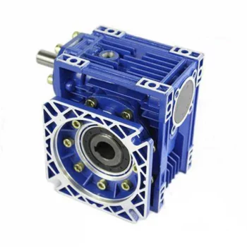
4. Worm Gear Reducers: Worm gears consist of a worm (screw) and a mating gear (worm wheel). They offer high torque reduction and are used for applications requiring high ratios, although they can be less efficient.
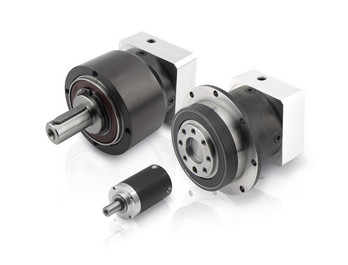
5. Planetary Gear Reducers: These reducers use a system of planetary gears to achieve high torque output in a compact design. They provide excellent torque multiplication and are commonly used in robotics and automation.
6. Cycloidal Gear Reducers: Cycloidal drives use an eccentric cam to achieve speed reduction. They offer high shock load resistance and are suitable for applications with frequent starting and stopping.
7. Harmonic Drive Reducers: Harmonic drives use a flexible spline to achieve high gear reduction ratios. They provide high precision and are commonly used in applications requiring accurate positioning.
8. Hypoid Gear Reducers: Hypoid gears have helical teeth and non-intersecting shafts, making them suitable for applications with space limitations. They offer high torque and efficiency.
Each type of gear reducer has its own advantages and limitations, and the choice depends on factors such as torque requirements, speed ratios, noise levels, space constraints, and application-specific needs.
editor by CX 2023-12-07
China Standard Reducer Spiral Bevel Helical Speed Reduction Agriculture Agricultural Cycloidal Servo High Precision Planetary Winch Track Wheel Slewing Drive Nmrv Worm Gearbox with Best Sales
Product Description
SC Transmission RC61 TransmissionGearbox for Agriculture Machine
Lawn Mower, Rotary Cutter, Rota Slasher
Product Description
1:1~1:1.93,540 RPM,65~80 HP
Detailed Photos
Company Profile
FAQ
Shipping
| Application: | Motor, Machinery, Agricultural Machinery |
|---|---|
| Hardness: | Hardened Tooth Surface |
| Gear Shape: | Bevel Gear |
| Step: | Single-Step |
| Type: | Gear Reducer |
| Color: | Depend on Customer/Blue/ Silver White/Grey |
| Samples: |
US$ 200/Piece
1 Piece(Min.Order) | |
|---|
| Customization: |
Available
| Customized Request |
|---|
Common Problems and Troubleshooting for Worm Gearboxes
Worm gearboxes, like any mechanical component, can experience various issues over time. Here are some common problems that may arise and possible troubleshooting steps:
- Overheating: Overheating can occur due to factors such as inadequate lubrication, excessive loads, or high operating temperatures. Check lubrication levels, ensure proper ventilation, and reduce loads if necessary.
- Noise and Vibration: Excessive noise and vibration may result from misalignment, worn gears, or improper meshing. Check for misalignment, inspect gear teeth for wear, and ensure proper gear meshing.
- Leakage: Oil leakage can be caused by damaged seals or gaskets. Inspect seals and gaskets, and replace them if necessary.
- Reduced Efficiency: Efficiency loss can occur due to friction, wear, or misalignment. Regularly monitor gearbox performance, ensure proper lubrication, and address any wear or misalignment issues.
- Backlash: Excessive backlash can affect precision and accuracy. Adjust gear meshing and reduce backlash to improve performance.
- Seizure or Binding: Seizure or binding can result from inadequate lubrication, debris, or misalignment. Clean the gearbox, ensure proper lubrication, and address misalignment issues.
- Worn Gears: Worn gear teeth can lead to poor performance. Regularly inspect gears for signs of wear, and replace worn gears as needed.
- Seal Wear: Seals can wear over time, leading to leakage and contamination. Inspect seals regularly and replace them if necessary.
If you encounter any of these problems, it's important to address them promptly to prevent further damage and maintain the performance of your worm gearbox. Regular maintenance, proper lubrication, and addressing issues early can help extend the lifespan and reliability of the gearbox.

Diagnosing and Fixing Oil Leakage in a Worm Gearbox
Oil leakage in a worm gearbox can lead to reduced lubrication, increased friction, and potential damage to the gearbox components. Here's a step-by-step process to diagnose and fix oil leakage:
- Inspect the Gearbox: Perform a visual inspection of the gearbox to identify the source of the leakage. Check for oil stains, wet spots, or oil pooling around the gearbox.
- Check Seals and Gaskets: Inspect the seals, gaskets, and O-rings for any signs of wear, cracks, or damage. These components are common points of leakage.
- Tighten Bolts and Fasteners: Ensure that all bolts, screws, and fasteners are properly tightened. Loose fasteners can create gaps that allow oil to escape.
- Replace Damaged Seals: If you find damaged seals or gaskets, replace them with new ones. Use seals that are compatible with the operating conditions and lubricant.
- Check Breather Vent: A clogged or malfunctioning breather vent can cause pressure buildup inside the gearbox, leading to leakage. Clean or replace the breather vent if necessary.
- Examine Shaft Seals: Check the shaft seals for wear or damage. If they're worn out, replace them with seals of the appropriate size and material.
- Use Proper Lubricant: Ensure that you're using the correct lubricant recommended for the gearbox. Using the wrong type of lubricant can cause leaks.
- Apply Sealants: In some cases, applying a suitable sealant to the joints and connections can help prevent leaks. Follow the manufacturer's instructions for proper application.
- Monitor Leakage: After addressing the issues, monitor the gearbox for any signs of continued leakage. If leakage persists, further investigation may be required.
- Regular Maintenance: Implement a regular maintenance schedule that includes checking seals, gaskets, and other potential leakage points. Timely maintenance can prevent future leakage issues.
If you're unsure about diagnosing or fixing oil leakage in a worm gearbox, consider consulting with a professional or gearbox manufacturer to ensure proper resolution.

Preventing Backlash in a Worm Gearbox
Backlash in a worm gearbox can lead to reduced accuracy, positioning errors, and decreased overall efficiency. Here are steps to prevent or minimize backlash:
- High-Quality Components: Use high-quality worm gears and worm wheels with tight manufacturing tolerances. Precision components will help reduce backlash.
- Proper Meshing: Ensure the worm gear and worm wheel are properly aligned and meshed. Improper meshing can lead to increased backlash.
- Preload: Applying a small amount of preload to the worm gear can help reduce backlash. However, excessive preload can increase friction and wear.
- Anti-Backlash Mechanisms: Consider using anti-backlash mechanisms, such as spring-loaded systems or adjustable shims, to compensate for any inherent backlash.
- Lubrication: Proper lubrication can reduce friction and play a role in minimizing backlash. Use a lubricant that provides good film strength and reduces wear.
- Maintenance: Regularly inspect and maintain the gearbox to identify and address any changes in backlash over time.
It's important to strike a balance between reducing backlash and maintaining smooth operation. Consulting with gearbox experts and following manufacturer guidelines will help you optimize your worm gearbox's performance while minimizing backlash.
editor by CX 2023-09-18