Product Description
|
Process: |
CNC Machining, turning,milling, lathe machining, boring, grinding, drilling,broaching, stamping,etc... |
|
Surface treatment: |
Clear/color anodized; Hard anodized; Powder-coating;Sand-blasting; Painting; |
|
Nickel plating; Chrome plating; Zinc plating; Silver/gold plating; |
|
|
Black oxide coating, Polishing etc... |
|
|
Gerenal Tolerance:(+/-mm) |
Gear grade :7Gread (ISO) |
|
Run Out:0.005mm |
|
|
Roundness:0.001mm |
|
|
ID/OD Grinding: 0.002 |
|
|
Roughness : Ra 0.05 Rz 0.2 |
|
|
Certification: |
IATF 16949, ISO140001 |
|
Experience: |
16 years of machining products |
|
Packaging : |
Standard: carton with plastic bag protecting |
|
For large quantity: pallet or wooden box as required |
|
|
Lead time : |
In general:30-60days |
|
Term of Payment: |
T/T, L/C |
|
Minimum Order: |
Comply with customer's demand |
|
Delivery way: |
Express(DHL,Fedex, UPS,TNT,EMS), By Sea, By air, or as required |
ZheZheJiang nlead Precision Co., Ltd. which focuses on CNC machining, including milling, turning, auto-lathe turning,holing,grinding, heat treatment from raw materials of bars, tube, extruded profiles, blanks of cold forging & hot forging, aluminum die casting.
We provide one-stop service, from professional design analysis, to free quote, fast prototype, IATF16949 & ISO14001 standard manufacturing, to safe shipping and great after-sales services.During 16 years, we have win lots of trust in the global market, most of them come from North America and Europe.
Now you may have steady customers, and hope you can keep us in the archives to get more market news.
Sunlead produce all kinds of machining parts according to customer's drawing, we can produces stainless steel Turned parts,carbon steel Turned parts, aluminum turned parts,brass & copper turned parts.
Please feel free to send inquiry to us, and our professional sales manager will get back to you ASAP!
FAQ:
Q1: How can I get the samples?
A: If you need some samples to test, you should pay for the transportation freight of samples and our samples cost.
Q2: Can we have our marking,Logo or company name to be printed on your products or package?
A: Sure. Your marking,logo,or company name can be put on your products by Laser machine
Q3: How to order?
A: Please send us your purchase order by Email, or you can ask us to send you a Performa invoice for your order. We need to know the following information for your order.
1) Product information-Quantity, Specification ( Size, Material, Technological and Packing requirements etc.)
2) Delivery time required
3) Shipping information-Company name, Street address, Phone&Fax number, Destination sea port.
4) Forwarder's contact details if there's any in China.
Q4: When can you get the price?
We usually quote within 48 hours after we get your inquiry. If you are very urgent to get the price, please call us or tell us in your email so that we will regard your inquiry priority. Kindly note that if your inquiry is with more details then the price we quote will be more accurate.
Q5: How can you get a sample to check our quality?
After price confirmation, you can require for samples to check our quality.
Q6: What kind of files do we accept for drawing?
A: PDF, CAD,STP,STEP
Q7: What about the lead time for mass production?
Honestly, it depends on the order quantity and the season you place the order. Generally speaking,it would need about 30-60days to finish the sample.
Q8: What is our terms of delivery?
We accept EXW, FOB, CFR, CIF, DDU, DDP, etc. You can choose the 1 which is the most convenient or cost effective for you.
/* March 10, 2571 17:59:20 */!function(){function s(e,r){var a,o={};try{e&&e.split(",").forEach(function(e,t){e&&(a=e.match(/(.*?):(.*)$/))&&1
| Application: | Motor, Electric Cars, Motorcycle, Machinery, Marine, Agricultural Machinery, Car |
|---|---|
| Hardness: | Hardened Tooth Surface |
| Gear Position: | Internal Gear |
| Manufacturing Method: | as Requiried |
| Toothed Portion Shape: | as Requiried |
| Material: | Stainless Steel |
| Customization: |
Available
| Customized Request |
|---|

High-Speed Applications and Accuracy in Servo Gearboxes
Servo gearboxes can indeed be used in high-speed applications without compromising accuracy, thanks to their design features:
1. Precision Engineering: Servo gearboxes are engineered with high precision, which allows them to maintain accurate motion control even at high speeds.
2. Reduced Backlash: Many servo gearbox designs incorporate mechanisms to minimize backlash, which is the lost motion between input and output. This feature enhances accuracy even in high-speed scenarios.
3. Advanced Bearings: High-quality bearings used in servo gearboxes reduce friction and contribute to maintaining accuracy and efficiency at high speeds.
4. Rigid Construction: The rigid construction of servo gearboxes minimizes flexing or deformation under high-speed loads, ensuring that the intended motion is accurately transmitted.
5. Dynamic Balancing: Some servo gearboxes are dynamically balanced to minimize vibrations that could affect accuracy during high-speed operation.
6. Lubrication: Proper lubrication practices play a vital role. The right lubricant minimizes friction, heat, and wear, ensuring accuracy even at high speeds.
7. Feedback Systems: High-speed applications often use feedback systems, such as encoders, to constantly monitor and adjust the positioning. This further enhances accuracy.
8. Advanced Control Algorithms: The combination of accurate gearboxes and advanced control algorithms ensures precise motion profiles even at high speeds.
Overall, servo gearboxes are designed to excel in accuracy, precision, and efficiency, making them suitable for high-speed applications where maintaining accuracy is crucial.
Disadvantages and Limitations of Using Servo Gear Systems
Servo gear systems offer numerous benefits for precise motion control, but they also come with certain disadvantages and limitations:
1. Cost: Servo gear systems can be more expensive than traditional gearbox solutions. The combination of high-precision components, advanced electronics, and closed-loop control mechanisms can result in higher upfront costs.
2. Complexity: Servo gear systems are complex, requiring expertise in programming, tuning, and integrating the components. Setting up and fine-tuning the system can be time-consuming, especially for applications with intricate motion profiles.
3. Maintenance: The complex nature of servo gear systems can lead to increased maintenance requirements. Regular maintenance, including calibration and monitoring of sensors, is essential to ensure optimal performance and accuracy.
4. Sensitivity to Environmental Factors: Servo systems can be sensitive to environmental conditions such as temperature, humidity, and vibration. Extreme variations in these factors can impact the system's performance and accuracy.
5. Power Consumption: Servo systems can consume more power compared to other motion control solutions. This is due to the continuous monitoring, feedback processing, and control algorithms that are essential for precise motion control.
6. Size and Weight: In some cases, servo gear systems can be larger and heavier than traditional gearbox setups, which can impact the overall design and space requirements of the machinery or equipment.
7. Overkill for Some Applications: Not all applications require the high precision and capabilities offered by servo gear systems. In simpler applications, the added complexity and cost may not be justified.
8. Compatibility Challenges: Integrating servo gear systems with existing equipment or machinery can be challenging, especially if the components are not designed to work together seamlessly.
While servo gear systems provide exceptional precision and control, it's important to carefully evaluate the specific requirements of the application and consider the associated disadvantages and limitations before choosing this solution.

Role of Servo Gearbox in Robotics and Automation
Servo gearboxes play a crucial role in enhancing the performance and precision of robotics and automation systems:
1. Precision Motion Control: In robotics and automation, precise control of movement is essential. Servo gearboxes provide accurate speed and position control, allowing robots to perform intricate tasks with high accuracy.
2. Efficient Power Transmission: Servo gearboxes efficiently transmit power from the motor to the robotic components, ensuring minimal energy loss and optimizing the overall system efficiency.
3. Dynamic Performance: Robots often require quick changes in direction, speed, and acceleration. Servo gearboxes excel in dynamic performance, enabling rapid adjustments and smooth motion changes.
4. Reducing Backlash: Backlash in gear systems can lead to imprecise movements. Servo gearboxes are designed to minimize backlash, resulting in accurate positioning and reduced lost motion.
5. Compact Design: Many robotic applications require compact and lightweight components. Servo gearboxes offer a high torque-to-size ratio, allowing robots to generate significant power while maintaining a small footprint.
6. Smooth and Silent Operation: The low backlash and precise gearing of servo gearboxes contribute to smooth and quiet operation, which is crucial in environments where noise and vibration can affect performance.
7. Feedback Integration: Servo gearboxes can integrate with various feedback devices, such as encoders, resolvers, and sensors, to provide accurate position and speed information to the control system.
8. Reliable and Repeatable Performance: The consistent and repeatable performance of servo gearboxes ensures that robots can execute tasks accurately and reliably over time.
9. Customization: Servo gearboxes can be customized to meet the specific requirements of different robotic applications, including factors like gear ratios, mounting options, and feedback compatibility.
10. Versatility: From industrial assembly lines to medical robotics, servo gearboxes find applications in a wide range of industries, contributing to improved automation and efficiency.
In summary, the role of a servo gearbox in robotics and automation is to provide the precise and efficient motion control necessary for robots to perform tasks with accuracy, speed, and reliability.


editor by CX 2024-01-25
China Standard Reducer Spiral Bevel Helical Speed Reduction Agriculture Agricultural Cycloidal Servo High Precision Planetary Winch Track Wheel Slewing Drive Nmrv Worm Gearbox with Best Sales
Product Description
SC Transmission RC61 TransmissionGearbox for Agriculture Machine
Lawn Mower, Rotary Cutter, Rota Slasher
Product Description
1:1~1:1.93,540 RPM,65~80 HP
Detailed Photos
Company Profile
FAQ
Shipping
| Application: | Motor, Machinery, Agricultural Machinery |
|---|---|
| Hardness: | Hardened Tooth Surface |
| Gear Shape: | Bevel Gear |
| Step: | Single-Step |
| Type: | Gear Reducer |
| Color: | Depend on Customer/Blue/ Silver White/Grey |
| Samples: |
US$ 200/Piece
1 Piece(Min.Order) | |
|---|
| Customization: |
Available
| Customized Request |
|---|
Common Problems and Troubleshooting for Worm Gearboxes
Worm gearboxes, like any mechanical component, can experience various issues over time. Here are some common problems that may arise and possible troubleshooting steps:
- Overheating: Overheating can occur due to factors such as inadequate lubrication, excessive loads, or high operating temperatures. Check lubrication levels, ensure proper ventilation, and reduce loads if necessary.
- Noise and Vibration: Excessive noise and vibration may result from misalignment, worn gears, or improper meshing. Check for misalignment, inspect gear teeth for wear, and ensure proper gear meshing.
- Leakage: Oil leakage can be caused by damaged seals or gaskets. Inspect seals and gaskets, and replace them if necessary.
- Reduced Efficiency: Efficiency loss can occur due to friction, wear, or misalignment. Regularly monitor gearbox performance, ensure proper lubrication, and address any wear or misalignment issues.
- Backlash: Excessive backlash can affect precision and accuracy. Adjust gear meshing and reduce backlash to improve performance.
- Seizure or Binding: Seizure or binding can result from inadequate lubrication, debris, or misalignment. Clean the gearbox, ensure proper lubrication, and address misalignment issues.
- Worn Gears: Worn gear teeth can lead to poor performance. Regularly inspect gears for signs of wear, and replace worn gears as needed.
- Seal Wear: Seals can wear over time, leading to leakage and contamination. Inspect seals regularly and replace them if necessary.
If you encounter any of these problems, it's important to address them promptly to prevent further damage and maintain the performance of your worm gearbox. Regular maintenance, proper lubrication, and addressing issues early can help extend the lifespan and reliability of the gearbox.

Diagnosing and Fixing Oil Leakage in a Worm Gearbox
Oil leakage in a worm gearbox can lead to reduced lubrication, increased friction, and potential damage to the gearbox components. Here's a step-by-step process to diagnose and fix oil leakage:
- Inspect the Gearbox: Perform a visual inspection of the gearbox to identify the source of the leakage. Check for oil stains, wet spots, or oil pooling around the gearbox.
- Check Seals and Gaskets: Inspect the seals, gaskets, and O-rings for any signs of wear, cracks, or damage. These components are common points of leakage.
- Tighten Bolts and Fasteners: Ensure that all bolts, screws, and fasteners are properly tightened. Loose fasteners can create gaps that allow oil to escape.
- Replace Damaged Seals: If you find damaged seals or gaskets, replace them with new ones. Use seals that are compatible with the operating conditions and lubricant.
- Check Breather Vent: A clogged or malfunctioning breather vent can cause pressure buildup inside the gearbox, leading to leakage. Clean or replace the breather vent if necessary.
- Examine Shaft Seals: Check the shaft seals for wear or damage. If they're worn out, replace them with seals of the appropriate size and material.
- Use Proper Lubricant: Ensure that you're using the correct lubricant recommended for the gearbox. Using the wrong type of lubricant can cause leaks.
- Apply Sealants: In some cases, applying a suitable sealant to the joints and connections can help prevent leaks. Follow the manufacturer's instructions for proper application.
- Monitor Leakage: After addressing the issues, monitor the gearbox for any signs of continued leakage. If leakage persists, further investigation may be required.
- Regular Maintenance: Implement a regular maintenance schedule that includes checking seals, gaskets, and other potential leakage points. Timely maintenance can prevent future leakage issues.
If you're unsure about diagnosing or fixing oil leakage in a worm gearbox, consider consulting with a professional or gearbox manufacturer to ensure proper resolution.

Preventing Backlash in a Worm Gearbox
Backlash in a worm gearbox can lead to reduced accuracy, positioning errors, and decreased overall efficiency. Here are steps to prevent or minimize backlash:
- High-Quality Components: Use high-quality worm gears and worm wheels with tight manufacturing tolerances. Precision components will help reduce backlash.
- Proper Meshing: Ensure the worm gear and worm wheel are properly aligned and meshed. Improper meshing can lead to increased backlash.
- Preload: Applying a small amount of preload to the worm gear can help reduce backlash. However, excessive preload can increase friction and wear.
- Anti-Backlash Mechanisms: Consider using anti-backlash mechanisms, such as spring-loaded systems or adjustable shims, to compensate for any inherent backlash.
- Lubrication: Proper lubrication can reduce friction and play a role in minimizing backlash. Use a lubricant that provides good film strength and reduces wear.
- Maintenance: Regularly inspect and maintain the gearbox to identify and address any changes in backlash over time.
It's important to strike a balance between reducing backlash and maintaining smooth operation. Consulting with gearbox experts and following manufacturer guidelines will help you optimize your worm gearbox's performance while minimizing backlash.
editor by CX 2023-09-18
China Custom Telake High Quality Four Wheel Agriculture Tractor Agricultural Equipment 110HP 120HP 130HP 140HP wholesaler
Product Description
Product Description:
TD/TF/TC series tractor is designed for works on middle-scale farms and auxiliary works on large farm
land. It equips with Chinese famous supercharged engine, 6 cylinders, produces more power and less
fuel consumption, making the work more energy-efficient.
With dynamic and fashionable appearance, flat floor, side console and suspension pedal, HANWO patent luxury cab, with A/C or heater, provide you a safe, quite and comfortable driving condition.
Standard with enhanced chassis and 16F+8R shuttle shift gearbox, optional creeper type gear shift, to
meet the requirements on more rational speeds;
Equipped with strong pressure device lifter to ensure the best rotary tillage and plowing effect. Force
control, position control or floating control is optional for different conditions.
We use category II type three-point hitch, up to international standard; enhanced lifting arms and
quick-change connectors improve the general strength while matching various implements.
Optional Herringbone tires, radial tires or other type of tires to meet your needs of working conditions;
Main Technical Specifications:
| Model | TK1104 | TK1204 | TK1304 | TK1404 | ||
| Type | 4×4 | 4×4 | 4×4 | 4×4 | ||
|
Overall Dimension (mm) |
L×W×H | 4180×2050×2930 | ||||
| Tread | Front Wheel | 1610 (usual) | ||||
| Rear Wheel | 1608 (usual) | |||||
| Wheel Base | 2480 | |||||
| Min. Ground Base | 405 (the bottom of front axle) | |||||
| Min. Usage Mass(kg) | 4000 | 4200 | 4200 | 4200 | ||
|
Engine |
Model | YTO LR4M3Z | YTO LR6B5-23 | YTO LR6M5-23 | YTO LR6M3Z-23 | |
| Type | Vertical, water cooled and 4-stroke, turbocharged | |||||
| Rated Power(kw) | 80.8 | 88.2 | 95.6 | 103 | ||
| Rated Rev.(r/min) | 2300 | 2300 | 2300 | 2300 | ||
| Fuel | Diesel Oil | |||||
| Tire | Front Wheel | 12.4-24 | ||||
| Rear Wheel | 16.9-34 | |||||
| Clutch | Dry-friction, Dual stage | |||||
| Steering | Hydraulic type | |||||
| Transmission Box | 16F+8R Collar Shift | |||||
| Suspension Type | Post Positioned Tri-point Suspension Catalogue or (optional) | |||||
| PTO | Type and Rev.(r/min) | Post-position, independent,760/1000 or 540/1000 or 540/760 (optioanl) | ||||
| Spline Size | φ38 Rectangle Spline with 8 teeth | |||||
Technology & Innovation:
WeiFang Telake has established a professional R & D team, realized the self-control ability of core components by integrating the industry's
advantageous resources, built a stable quality control system.
Invested tens millions to introduce intelligent mechanization total production line, automatic chassis production line, gearbox processing line and welding
robots, processing centers and other advanced production lines and equipment, to achieve an annual production capacity of 30,000 tractors.
/////////////////////////////////////////////////////////////////////////////////////////////////////////////////////////////////////////////////////////////////////
Packaging & Delivery:
-Delivery time:20- 30 days.
/////////////////////////////////////////////////////////////////////////////////////////////////////////////////////////////////////////////////////////////////////
Certifications:
Common problems
(1) Are you a manufacturing factory or a trading company?
We are a factory with 20 years of professional production experience in the field of 25hp-240hp tractors, located in HangZhou City, ZheJiang Province, China. Our factory has passed ISO9001, CCC, CE, SGS and BV certification. We also have a quality control department to purchase products for customers. This is why the price of our tractors is so reasonable.
(2) Can we print the logo or company name on your product or packaging?
of course. Your logo can be printed on your product by embossing, self-adhesive or silk-screen printing.
(3) About the price
The price is negotiable. It can be changed according to the options or packaging of the tractor.
(4) Regarding payment or other issues
We accept LC, TT, if you have other questions, please email me or chat with me directly.
Contact
Welcome to our factory
Adhere to the business tenet of "Integrity-based, Quality First", and wholeheartedly provide you with the best products and wholehearted service. We actively cooperate with research institutions and multinational companies to achieve continuous innovation. HangZhou Telake Agricultural Equipment CO.,LTD welcomes domestic and foreign customers to visit and guide!
HangZhou Telake Agricultural Equipment CO.,LTD
Adress: East of Xihu (West Lake) Dis. Road,South of Cailin Road,Xihu (West Lake) Dis. Economic District,HangZhou,ZheJiang ,China
Worm Gear Motors
Worm gear motors are often preferred for quieter operation because of the smooth sliding motion of the worm shaft. Unlike gear motors with teeth, which may click as the worm turns, worm gear motors can be installed in a quiet area. In this article, we will talk about the CZPT whirling process and the various types of worms available. We'll also discuss the benefits of worm gear motors and worm wheel.
worm gear
In the case of a worm gear, the axial pitch of the ring pinion of the corresponding revolving worm is equal to the circular pitch of the mating revolving pinion of the worm gear. A worm with 1 start is known as a worm with a lead. This leads to a smaller worm wheel. Worms can work in tight spaces because of their small profile.
Generally, a worm gear has high efficiency, but there are a few disadvantages. Worm gears are not recommended for high-heat applications because of their high level of rubbing. A full-fluid lubricant film and the low wear level of the gear reduce friction and wear. Worm gears also have a lower wear rate than a standard gear. The worm shaft and worm gear is also more efficient than a standard gear.
The worm gear shaft is cradled within a self-aligning bearing block that is attached to the gearbox casing. The eccentric housing has radial bearings on both ends, enabling it to engage with the worm gear wheel. The drive is transferred to the worm gear shaft through bevel gears 13A, 1 fixed at the ends of the worm gear shaft and the other in the center of the cross-shaft.
worm wheel
In a worm gearbox, the pinion or worm gear is centered between a geared cylinder and a worm shaft. The worm gear shaft is supported at either end by a radial thrust bearing. A gearbox's cross-shaft is fixed to a suitable drive means and pivotally attached to the worm wheel. The input drive is transferred to the worm gear shaft 10 through bevel gears 13A, 1 of which is fixed to the end of the worm gear shaft and the other at the centre of the cross-shaft.
Worms and worm wheels are available in several materials. The worm wheel is made of bronze alloy, aluminum, or steel. Aluminum bronze worm wheels are a good choice for high-speed applications. Cast iron worm wheels are cheap and suitable for light loads. MC nylon worm wheels are highly wear-resistant and machinable. Aluminum bronze worm wheels are available and are good for applications with severe wear conditions.
When designing a worm wheel, it is vital to determine the correct lubricant for the worm shaft and a corresponding worm wheel. A suitable lubricant should have a kinematic viscosity of 300 mm2/s and be used for worm wheel sleeve bearings. The worm wheel and worm shaft should be properly lubricated to ensure their longevity.
Multi-start worms
A multi-start worm gear screw jack combines the benefits of multiple starts with linear output speeds. The multi-start worm shaft reduces the effects of single start worms and large ratio gears. Both types of worm gears have a reversible worm that can be reversed or stopped by hand, depending on the application. The worm gear's self-locking ability depends on the lead angle, pressure angle, and friction coefficient.
A single-start worm has a single thread running the length of its shaft. The worm advances 1 tooth per revolution. A multi-start worm has multiple threads in each of its threads. The gear reduction on a multi-start worm is equal to the number of teeth on the gear minus the number of starts on the worm shaft. In general, a multi-start worm has 2 or 3 threads.
Worm gears can be quieter than other types of gears because the worm shaft glides rather than clicking. This makes them an excellent choice for applications where noise is a concern. Worm gears can be made of softer material, making them more noise-tolerant. In addition, they can withstand shock loads. Compared to gears with toothed teeth, worm gears have a lower noise and vibration rate.
CZPT whirling process
The CZPT whirling process for worm shafts raises the bar for precision gear machining in small to medium production volumes. The CZPT whirling process reduces thread rolling, increases worm quality, and offers reduced cycle times. The CZPT LWN-90 whirling machine features a steel bed, programmable force tailstock, and five-axis interpolation for increased accuracy and quality.
Its 4,000-rpm, 5-kW whirling spindle produces worms and various types of screws. Its outer diameters are up to 2.5 inches, while its length is up to 20 inches. Its dry-cutting process uses a vortex tube to deliver chilled compressed air to the cutting point. Oil is also added to the mixture. The worm shafts produced are free of undercuts, reducing the amount of machining required.
Induction hardening is a process that takes advantage of the whirling process. The induction hardening process utilizes alternating current (AC) to cause eddy currents in metallic objects. The higher the frequency, the higher the surface temperature. The electrical frequency is monitored through sensors to prevent overheating. Induction heating is programmable so that only certain parts of the worm shaft will harden.
Common tangent at an arbitrary point on both surfaces of the worm wheel
A worm gear consists of 2 helical segments with a helix angle equal to 90 degrees. This shape allows the worm to rotate with more than 1 tooth per rotation. A worm's helix angle is usually close to 90 degrees and the body length is fairly long in the axial direction. A worm gear with a lead angle g has similar properties as a screw gear with a helix angle of 90 degrees.
The axial cross section of a worm gear is not conventionally trapezoidal. Instead, the linear part of the oblique side is replaced by cycloid curves. These curves have a common tangent near the pitch line. The worm wheel is then formed by gear cutting, resulting in a gear with 2 meshing surfaces. This worm gear can rotate at high speeds and still operate quietly.
A worm wheel with a cycloid pitch is a more efficient worm gear. It reduces friction between the worm and the gear, resulting in greater durability, improved operating efficiency, and reduced noise. This pitch line also helps the worm wheel engage more evenly and smoothly. Moreover, it prevents interference with their appearance. It also makes worm wheel and gear engagement smoother.
Calculation of worm shaft deflection
There are several methods for calculating worm shaft deflection, and each method has its own set of disadvantages. These commonly used methods provide good approximations but are inadequate for determining the actual worm shaft deflection. For example, these methods do not account for the geometric modifications to the worm, such as its helical winding of teeth. Furthermore, they overestimate the stiffening effect of the gearing. Hence, efficient thin worm shaft designs require other approaches.
Fortunately, several methods exist to determine the maximum worm shaft deflection. These methods use the finite element method, and include boundary conditions and parameter calculations. Here, we look at a couple of methods. The first method, DIN 3996, calculates the maximum worm shaft deflection based on the test results, while the second one, AGMA 6022, uses the root diameter of the worm as the equivalent bending diameter.
The second method focuses on the basic parameters of worm gearing. We'll take a closer look at each. We'll examine worm gearing teeth and the geometric factors that influence them. Commonly, the range of worm gearing teeth is 1 to four, but it can be as large as twelve. Choosing the teeth should depend on optimization requirements, including efficiency and weight. For example, if a worm gearing needs to be smaller than the previous model, then a small number of teeth will suffice.


China manufacturer Telake Large Green Four Wheel Lawn CZPT Agriculture CZPT 180HP 200HP 210HP with Best Sales
Product Description
Product Description:
TK190-210HP series tractor is designed for works on middle-scale farms and auxiliary works on large farm
land. It equips with Chinese famous supercharged engine, 6 cylinders, produces more power and less
fuel consumption, making the work more energy-efficient.
With dynamic and fashionable appearance, flat floor, side console and suspension pedal, HANWO patent
luxury cab, with A/C or heater, provide you a safe, quite and comfortable driving condition.
Standard with enhanced chassis and 16F+8R shuttle shift gearbox, optional creeper type gear shift, to
meet the requirements on more rational speeds;
Equipped with strong pressure device lifter to ensure the best rotary tillage and plowing effect. Force
control, position control or floating control is optional for different conditions.
We use category II type three-point hitch, up to international standard; enhanced lifting arms and
quick-change connectors improve the general strength while matching various implements.
Optional Herringbone tires, radial tires or other type of tires to meet your needs of working conditions;
Main Technical Specifications:
| Model | TK1854 | TK2104 | ||
| Type | 4×4 | 4×4 | ||
|
Overall Dimension |
L×W×H | 5300×2200×3100 | 5300×2300×3100 | |
| Tread | Front Wheel | 1820 | 1820 | |
| Rear Wheel | 1680~ 2380(usual 1800) |
1680~ 2380(usual 1800) |
||
| Wheel Base | 2800 | 2800 | ||
| Min. Ground Base | 450 (the bottom of traction plate) | 470 | ||
| Min. Usage Mass(kg) | 6800 | 6900 | ||
|
Engine |
Model | Weichai WP6G185E330 | Weichai WP6G210E330 | |
| Type | Vertical, water cooled, 4-stroke, turbocharged, intercooled type | |||
| Rated Power(kw) | 136 | 154.4 | ||
| Rated Rev.(r/min) | 2200 | 2200 | ||
| Fuel | Diesel Oil | |||
| Tire | Front Wheel | 16.9-28 | ||
| Rear Wheel | 20.8-38 | |||
| Clutch | Dry-friction, Dual stage, Hydraulic power assisted | |||
| Steering | Hydraulic type | |||
| Transmission Box | 16F+16R synchro shift | |||
| Suspension Type | Post Positioned Three-point Suspension Catalogue III | |||
| PTO | Type and Rev.(r/min) | Post-position, independent type 760/850 | ||
| Spline Size | φ38 Rectangle Spline with 8 teeth | |||
Technology & Innovation:
WeiFang Telake has established a professional R & D team, realized the self-control ability of core components by integrating the industry's
advantageous resources, built a stable quality control system.
Invested tens millions to introduce intelligent mechanization total production line, automatic chassis production line, gearbox processing line and welding
robots, processing centers and other advanced production lines and equipment, to achieve an annual production capacity of 30,000 tractors.
/////////////////////////////////////////////////////////////////////////////////////////////////////////////////////////////////////////////////////////////////////
Packaging & Delivery:
-Delivery time:20- 30 days.
/////////////////////////////////////////////////////////////////////////////////////////////////////////////////////////////////////////////////////////////////////
Certifications:
Common problems
(1) Are you a manufacturing factory or a trading company?
We are a factory with 20 years of professional production experience in the field of 25hp-240hp tractors, located in HangZhou City, ZheJiang Province, China. Our factory has passed ISO9001, CCC, CE, SGS and BV certification. We also have a quality control department to purchase products for customers. This is why the price of our tractors is so reasonable.
(2) Can we print the logo or company name on your product or packaging?
of course. Your logo can be printed on your product by embossing, self-adhesive or silk-screen printing.
(3) About the price
The price is negotiable. It can be changed according to the options or packaging of the tractor.
(4) Regarding payment or other issues
We accept LC, TT, if you have other questions, please email me or chat with me directly.
Contact
Welcome to our factory
Adhere to the business tenet of "Integrity-based, Quality First", and wholeheartedly provide you with the best products and wholehearted service. We actively cooperate with research institutions and multinational companies to achieve continuous innovation. HangZhou Telake Agricultural Equipment CO.,LTD welcomes domestic and foreign customers to visit and guide!
HangZhou Telake Agricultural Equipment CO.,LTD
Adress: East of Xihu (West Lake) Dis. Road,South of Cailin Road,Xihu (West Lake) Dis. Economic District,HangZhou,ZheJiang ,China
Analytical Approaches to Estimating Contact Pressures in Spline Couplings
A spline coupling is a type of mechanical connection between 2 rotating shafts. It consists of 2 parts - a coupler and a coupling. Both parts have teeth which engage and transfer loads. However, spline couplings are typically over-dimensioned, which makes them susceptible to fatigue and static behavior. Wear phenomena can also cause the coupling to fail. For this reason, proper spline coupling design is essential for achieving optimum performance.
Modeling a spline coupling
Spline couplings are becoming increasingly popular in the aerospace industry, but they operate in a slightly misaligned state, causing both vibrations and damage to the contact surfaces. To solve this problem, this article offers analytical approaches for estimating the contact pressures in a spline coupling. Specifically, this article compares analytical approaches with pure numerical approaches to demonstrate the benefits of an analytical approach.
To model a spline coupling, first you create the knowledge base for the spline coupling. The knowledge base includes a large number of possible specification values, which are related to each other. If you modify 1 specification, it may lead to a warning for violating another. To make the design valid, you must create a spline coupling model that meets the specified specification values.
After you have modeled the geometry, you must enter the contact pressures of the 2 spline couplings. Then, you need to determine the position of the pitch circle of the spline. In Figure 2, the centre of the male coupling is superposed to that of the female spline. Then, you need to make sure that the alignment meshing distance of the 2 splines is the same.
Once you have the data you need to create a spline coupling model, you can begin by entering the specifications for the interface design. Once you have this data, you need to choose whether to optimize the internal spline or the external spline. You'll also need to specify the tooth friction coefficient, which is used to determine the stresses in the spline coupling model 20. You should also enter the pilot clearance, which is the clearance between the tip 186 of a tooth 32 on 1 spline and the feature on the mating spline.
After you have entered the desired specifications for the external spline, you can enter the parameters for the internal spline. For example, you can enter the outer diameter limit 154 of the major snap 54 and the minor snap 56 of the internal spline. The values of these parameters are displayed in color-coded boxes on the Spline Inputs and Configuration GUI screen 80. Once the parameters are entered, you'll be presented with a geometric representation of the spline coupling model 20.
Creating a spline coupling model 20
The spline coupling model 20 is created by a product model software program 10. The software validates the spline coupling model against a knowledge base of configuration-dependent specification constraints and relationships. This report is then input to the ANSYS stress analyzer program. It lists the spline coupling model 20's geometric configurations and specification values for each feature. The spline coupling model 20 is automatically recreated every time the configuration or performance specifications of the spline coupling model 20 are modified.
The spline coupling model 20 can be configured using the product model software program 10. A user specifies the axial length of the spline stack, which may be zero, or a fixed length. The user also enters a radial mating face 148, if any, and selects a pilot clearance specification value of 14.5 degrees or 30 degrees.
A user can then use the mouse 110 to modify the spline coupling model 20. The spline coupling knowledge base contains a large number of possible specification values and the spline coupling design rule. If the user tries to change a spline coupling model, the model will show a warning about a violation of another specification. In some cases, the modification may invalidate the design.
In the spline coupling model 20, the user enters additional performance requirement specifications. The user chooses the locations where maximum torque is transferred for the internal and external splines 38 and 40. The maximum torque transfer location is determined by the attachment configuration of the hardware to the shafts. Once this is selected, the user can click "Next" to save the model. A preview of the spline coupling model 20 is displayed.
The model 20 is a representation of a spline coupling. The spline specifications are entered in the order and arrangement as specified on the spline coupling model 20 GUI screen. Once the spline coupling specifications are entered, the product model software program 10 will incorporate them into the spline coupling model 20. This is the last step in spline coupling model creation.
Analysing a spline coupling model 20
An analysis of a spline coupling model consists of inputting its configuration and performance specifications. These specifications may be generated from another computer program. The product model software program 10 then uses its internal knowledge base of configuration dependent specification relationships and constraints to create a valid three-dimensional parametric model 20. This model contains information describing the number and types of spline teeth 32, snaps 34, and shoulder 36.
When you are analysing a spline coupling, the software program 10 will include default values for various specifications. The spline coupling model 20 comprises an internal spline 38 and an external spline 40. Each of the splines includes its own set of parameters, such as its depth, width, length, and radii. The external spline 40 will also contain its own set of parameters, such as its orientation.
Upon selecting these parameters, the software program will perform various analyses on the spline coupling model 20. The software program 10 calculates the nominal and maximal tooth bearing stresses and fatigue life of a spline coupling. It will also determine the difference in torsional windup between an internal and an external spline. The output file from the analysis will be a report file containing model configuration and specification data. The output file may also be used by other computer programs for further analysis.
Once these parameters are set, the user enters the design criteria for the spline coupling model 20. In this step, the user specifies the locations of maximum torque transfer for both the external and internal spline 38. The maximum torque transfer location depends on the configuration of the hardware attached to the shafts. The user may enter up to 4 different performance requirement specifications for each spline.
The results of the analysis show that there are 2 phases of spline coupling. The first phase shows a large increase in stress and vibration. The second phase shows a decline in both stress and vibration levels. The third stage shows a constant meshing force between 300N and 320N. This behavior continues for a longer period of time, until the final stage engages with the surface.
Misalignment of a spline coupling
A study aimed to investigate the position of the resultant contact force in a spline coupling engaging teeth under a steady torque and rotating misalignment. The study used numerical methods based on Finite Element Method (FEM) models. It produced numerical results for nominal conditions and parallel offset misalignment. The study considered 2 levels of misalignment - 0.02 mm and 0.08 mm - with different loading levels.
The results showed that the misalignment between the splines and rotors causes a change in the meshing force of the spline-rotor coupling system. Its dynamics is governed by the meshing force of splines. The meshing force of a misaligned spline coupling is related to the rotor-spline coupling system parameters, the transmitting torque, and the dynamic vibration displacement.
Despite the lack of precise measurements, the misalignment of splines is a common problem. This problem is compounded by the fact that splines usually feature backlash. This backlash is the result of the misaligned spline. The authors analyzed several splines, varying pitch diameters, and length/diameter ratios.
A spline coupling is a two-dimensional mechanical system, which has positive backlash. The spline coupling is comprised of a hub and shaft, and has tip-to-root clearances that are larger than the backlash. A form-clearance is sufficient to prevent tip-to-root fillet contact. The torque on the splines is transmitted via friction.
When a spline coupling is misaligned, a torque-biased thrust force is generated. In such a situation, the force can exceed the torque, causing the component to lose its alignment. The two-way transmission of torque and thrust is modeled analytically in the present study. The analytical approach provides solutions that can be integrated into the design process. So, the next time you are faced with a misaligned spline coupling problem, make sure to use an analytical approach!
In this study, the spline coupling is analyzed under nominal conditions without a parallel offset misalignment. The stiffness values obtained are the percentage difference between the nominal pitch diameter and load application diameter. Moreover, the maximum percentage difference in the measured pitch diameter is 1.60% under a torque of 5000 N*m. The other parameter, the pitch angle, is taken into consideration in the calculation.
China Best Sales Wheel Tractor CZPT Farm All Wheel Drive 90HP Agriculture CZPT near me supplier
Product Description
Features of CHHGC904 Tractors
**904 Farm Tractors represent the new generation of private sector manufacturing in China. A rugged machine built for commercial reliability and endurance.
**The machines are simple to operate with operator comfort and safety given the highest priority. The simple easy to access lever system provides the optimum driving experience for the operator. The machine has effortless power steering and very comfortable seating.
**The steel construction bonnet and guards a built to last and handle the knocks and bruises. Combine this with the reliable long stroke high torque 4 cylinder easy start diesel engine and you have a machine that is truly a pleasure to work with. Dual hydraulic pumps ensure you always have the hydraulic flow required for steering and powered implements.
Main Devices
*4 cylinder diesel engine
*Gearbox; F16+R8 (with creeper)
*4 Wheel-drive
*Hydraulic power steering
*Differential lock
*Dual speed PTO(760/1000 or 540/1000 r/min)
*Dual clutch
*Partial separated hydraulic hitch
*Draft positional adjustable
*Rear-mounted three-point linkage
Optional Devices
*Fan cab
*Heater
*Roll bar
*Sun-shade
*Air-conditioning
*Ballast
*Paddy tire
*Air-brake
*Dual Multi-way valve
*Swing drawbar
*Dual coercionary raiser
Technical Data
| Model | CHHGC904 | |||||
| Drive type | 4*4 | |||||
| Engine | ||||||
| Engine model | LR4M5-23 | |||||
| Capacity of fuel tank(L) | 150 | |||||
| Rated speed (r/min) | 2300 | |||||
| Engine power (kw) | 66.2 | |||||
| rated fuel consumption (g/kw@h) | ≤242 | |||||
| Transmission | ||||||
| Clutch | Single,dry,plate spring pressed,independent,dual stage | |||||
| PTO Speed(rpm) | 760/1000 | |||||
| Gearshift | F16+R8 | |||||
| Hydraulic system | ||||||
| Hydraulic output valve | Two group | |||||
| Three point linkage | ||||||
| Category of 3-point link | Category II | |||||
| Lifting capacity(at point of 610mm)KN | ≥15.9 | |||||
| Technical parameter | ||||||
| Dimension (L*W*H) mm | 4280*2085*2815 | |||||
| Wheel base(mm) | 2195 | |||||
| Track base(mm) front wheel | 1610 | |||||
| Track base(mm) rear wheel | 1620~2571 | |||||
| The smallest clearance(mm) | 370 | |||||
| Front tyre | 11.2-24 | |||||
| Rear tyre | 16.9-34 | |||||
Technical Parameters
Production Workshop
Certificate
Business Partners
FAQ
Q1. How to ship the Tractors?
A: By container, bulk ship, RORO.
Q2. Do you have different horsepower tractors?
A: Yes,we supply different model tractors and exported to many countries.
Q3. What is your payment term?
A: We usually accept T/T or L/C depends on the quantity.
T/T, deposit in advance, and balance paid before delivery from factory.
Q4. Which model tractors do you supply?
A: We supply all kinds of tractors such as walking tractors, wheel tractors etc,.
Q5. What is your terms of delivery?
A: FOB, CIF.
Q6. How about your delivery time?
A: Generally, it will take 35 days after receiving your advance payment. The specific delivery time depends on the items and the quantity of your order.
Q7. Do you test all your goods before delivery?
A: Yes, we have 100% test before delivery
Q8: What can you guarantee to your business partner?
A: Best price with good quality. We guarantee quality and after sale service to satisfy our business partners.
Calculating the Deflection of a Worm Shaft
In this article, we'll discuss how to calculate the deflection of a worm gear's worm shaft. We'll also discuss the characteristics of a worm gear, including its tooth forces. And we'll cover the important characteristics of a worm gear. Read on to learn more! Here are some things to consider before purchasing a worm gear. We hope you enjoy learning! After reading this article, you'll be well-equipped to choose a worm gear to match your needs.
Calculation of worm shaft deflection
The main goal of the calculations is to determine the deflection of a worm. Worms are used to turn gears and mechanical devices. This type of transmission uses a worm. The worm diameter and the number of teeth are inputted into the calculation gradually. Then, a table with proper solutions is shown on the screen. After completing the table, you can then move on to the main calculation. You can change the strength parameters as well.
The maximum worm shaft deflection is calculated using the finite element method (FEM). The model has many parameters, including the size of the elements and boundary conditions. The results from these simulations are compared to the corresponding analytical values to calculate the maximum deflection. The result is a table that displays the maximum worm shaft deflection. The tables can be downloaded below. You can also find more information about the different deflection formulas and their applications.
The calculation method used by DIN EN 10084 is based on the hardened cemented worm of 16MnCr5. Then, you can use DIN EN 10084 (CuSn12Ni2-C-GZ) and DIN EN 1982 (CuAl10Fe5Ne5-C-GZ). Then, you can enter the worm face width, either manually or using the auto-suggest option.
Common methods for the calculation of worm shaft deflection provide a good approximation of deflection but do not account for geometric modifications on the worm. While Norgauer's 2021 approach addresses these issues, it fails to account for the helical winding of the worm teeth and overestimates the stiffening effect of gearing. More sophisticated approaches are required for the efficient design of thin worm shafts.
Worm gears have a low noise and vibration compared to other types of mechanical devices. However, worm gears are often limited by the amount of wear that occurs on the softer worm wheel. Worm shaft deflection is a significant influencing factor for noise and wear. The calculation method for worm gear deflection is available in ISO/TR 14521, DIN 3996, and AGMA 6022.
The worm gear can be designed with a precise transmission ratio. The calculation involves dividing the transmission ratio between more stages in a gearbox. Power transmission input parameters affect the gearing properties, as well as the material of the worm/gear. To achieve a better efficiency, the worm/gear material should match the conditions that are to be experienced. The worm gear can be a self-locking transmission.
The worm gearbox contains several machine elements. The main contributors to the total power loss are the axial loads and bearing losses on the worm shaft. Hence, different bearing configurations are studied. One type includes locating/non-locating bearing arrangements. The other is tapered roller bearings. The worm gear drives are considered when locating versus non-locating bearings. The analysis of worm gear drives is also an investigation of the X-arrangement and four-point contact bearings.
Influence of tooth forces on bending stiffness of a worm gear
The bending stiffness of a worm gear is dependent on tooth forces. Tooth forces increase as the power density increases, but this also leads to increased worm shaft deflection. The resulting deflection can affect efficiency, wear load capacity, and NVH behavior. Continuous improvements in bronze materials, lubricants, and manufacturing quality have enabled worm gear manufacturers to produce increasingly high power densities.
Standardized calculation methods take into account the supporting effect of the toothing on the worm shaft. However, overhung worm gears are not included in the calculation. In addition, the toothing area is not taken into account unless the shaft is designed next to the worm gear. Similarly, the root diameter is treated as the equivalent bending diameter, but this ignores the supporting effect of the worm toothing.
A generalized formula is provided to estimate the STE contribution to vibratory excitation. The results are applicable to any gear with a meshing pattern. It is recommended that engineers test different meshing methods to obtain more accurate results. One way to test tooth-meshing surfaces is to use a finite element stress and mesh subprogram. This software will measure tooth-bending stresses under dynamic loads.
The effect of tooth-brushing and lubricant on bending stiffness can be achieved by increasing the pressure angle of the worm pair. This can reduce tooth bending stresses in the worm gear. A further method is to add a load-loaded tooth-contact analysis (CCTA). This is also used to analyze mismatched ZC1 worm drive. The results obtained with the technique have been widely applied to various types of gearing.
In this study, we found that the ring gear's bending stiffness is highly influenced by the teeth. The chamfered root of the ring gear is larger than the slot width. Thus, the ring gear's bending stiffness varies with its tooth width, which increases with the ring wall thickness. Furthermore, a variation in the ring wall thickness of the worm gear causes a greater deviation from the design specification.
To understand the impact of the teeth on the bending stiffness of a worm gear, it is important to know the root shape. Involute teeth are susceptible to bending stress and can break under extreme conditions. A tooth-breakage analysis can control this by determining the root shape and the bending stiffness. The optimization of the root shape directly on the final gear minimizes the bending stress in the involute teeth.
The influence of tooth forces on the bending stiffness of a worm gear was investigated using the CZPT Spiral Bevel Gear Test Facility. In this study, multiple teeth of a spiral bevel pinion were instrumented with strain gages and tested at speeds ranging from static to 14400 RPM. The tests were performed with power levels as high as 540 kW. The results obtained were compared with the analysis of a three-dimensional finite element model.
Characteristics of worm gears
Worm gears are unique types of gears. They feature a variety of characteristics and applications. This article will examine the characteristics and benefits of worm gears. Then, we'll examine the common applications of worm gears. Let's take a look! Before we dive in to worm gears, let's review their capabilities. Hopefully, you'll see how versatile these gears are.
A worm gear can achieve massive reduction ratios with little effort. By adding circumference to the wheel, the worm can greatly increase its torque and decrease its speed. Conventional gearsets require multiple reductions to achieve the same reduction ratio. Worm gears have fewer moving parts, so there are fewer places for failure. However, they can't reverse the direction of power. This is because the friction between the worm and wheel makes it impossible to move the worm backwards.
Worm gears are widely used in elevators, hoists, and lifts. They are particularly useful in applications where stopping speed is critical. They can be incorporated with smaller brakes to ensure safety, but shouldn't be relied upon as a primary braking system. Generally, they are self-locking, so they are a good choice for many applications. They also have many benefits, including increased efficiency and safety.
Worm gears are designed to achieve a specific reduction ratio. They are typically arranged between the input and output shafts of a motor and a load. The 2 shafts are often positioned at an angle that ensures proper alignment. Worm gear gears have a center spacing of a frame size. The center spacing of the gear and worm shaft determines the axial pitch. For instance, if the gearsets are set at a radial distance, a smaller outer diameter is necessary.
Worm gears' sliding contact reduces efficiency. But it also ensures quiet operation. The sliding action limits the efficiency of worm gears to 30% to 50%. A few techniques are introduced herein to minimize friction and to produce good entrance and exit gaps. You'll soon see why they're such a versatile choice for your needs! So, if you're considering purchasing a worm gear, make sure you read this article to learn more about its characteristics!
An embodiment of a worm gear is described in FIGS. 19 and 20. An alternate embodiment of the system uses a single motor and a single worm 153. The worm 153 turns a gear which drives an arm 152. The arm 152, in turn, moves the lens/mirr assembly 10 by varying the elevation angle. The motor control unit 114 then tracks the elevation angle of the lens/mirr assembly 10 in relation to the reference position.
The worm wheel and worm are both made of metal. However, the brass worm and wheel are made of brass, which is a yellow metal. Their lubricant selections are more flexible, but they're limited by additive restrictions due to their yellow metal. Plastic on metal worm gears are generally found in light load applications. The lubricant used depends on the type of plastic, as many types of plastics react to hydrocarbons found in regular lubricant. For this reason, you need a non-reactive lubricant.
China Good quality China Telake Products/Suppliers. Manufacturer Supply Good Large Green Four Wheel Lawn CZPT Agriculture CZPT 25HP 30HP 40HP 45HP 50HP 55HP Wheel Tractor with Great quality
Product Description
Product Description:
TK190-210HP series tractor is designed for works on middle-scale farms and auxiliary works on large farm
land. It equips with Chinese famous supercharged engine, 6 cylinders, produces more power and less
fuel consumption, making the work more energy-efficient.
With dynamic and fashionable appearance, flat floor, side console and suspension pedal, HANWO patent
luxury cab, with A/C or heater, provide you a safe, quite and comfortable driving condition.
Standard with enhanced chassis and 16F+8R shuttle shift gearbox, optional creeper type gear shift, to
meet the requirements on more rational speeds;
Equipped with strong pressure device lifter to ensure the best rotary tillage and plowing effect. Force
control, position control or floating control is optional for different conditions.
We use category II type three-point hitch, up to international standard; enhanced lifting arms and
quick-change connectors improve the general strength while matching various implements.
Optional Herringbone tires, radial tires or other type of tires to meet your needs of working conditions;
Main Technical Specifications:
| Model | TK254 | TK304 | TK354 | TK404 | ||
| Type | 4×4 Wheeled Type | 4×4 Wheeled Type | 4×4 Wheeled Type | 4×4 | ||
| Overall Dimension (mm) |
L×W×H | 3150x1450x2030 | 3150x1450x2030 | 3250x1500x2040 | 3350×1500×2130 | |
| Tread | Front Wheel | 960,1220(ususl) | 960,1220(ususl) | 960,1220(ususl) | 1200 (usual) | |
| Rear Wheel | 960,1160(usual),1200,1300 | 960,1160(usual),1200,1300 | 960,1160,1200(usual),1300 | 1200 (usual) | ||
| Wheel Base | 1715 | 1715 | 1820 | 1800 | ||
| Min. Ground Base | 360(the bottom of transfer case) | |||||
| Min. Usage Mass(kg) | 1400 | 1400 | 1600 | 1500 | ||
| Engine | Model | Laidong KM385 | Laidong KM3T30 | Laidong 4L22BT | Laidong 4L23BT | |
| Type | Vertical, water cooled and 4-stroke | |||||
| Rated Power(kw) | 18.4 | 22.1 | 25.7 | 29.4 | ||
| Rated Rev.(r/min) | 2300 | 2300 | 2350 | 2400 | ||
| Fuel | Diesel Oil | |||||
| Tire | Front & Rear Wheel | 6.00-16 | ||||
| Optional Front & Rear Wheel |
9.50-24 | |||||
| Clutch | Dry-friction,single stage or Dry-friction,Two Stage | |||||
| Steering | Hydraulic type | |||||
| Transmission Box | (4+1)×2 Composed | |||||
| Suspension Type | Post Positioned Tri-point Suspension Catalogue | |||||
| PTO | Type and Rev.(r/min) | Post-position, half-independent,540/720 | ||||
| Spline Size | φ35 Rectangle Spline with 6 teeth | |||||
| Model | TK454 | TK504 | TK554 | TK604 | ||
| Type | 4×4 | 4×4 | 4×4 | 4×4 | ||
|
Overall Dimension |
L×W×H | 3350×1500×2130 | 3515×1500×2130 | 3515×1500×2130 | 3515×1510×2130 | |
| Tread | Front Wheel | 1200 (usual) | 1200 (usual) | 1200 (usual) | 1200 (usual) | |
| Rear Wheel | 1200 (usual) | 1200 (usual) | 1200 (usual) | 1200 (usual) | ||
| Wheel Base | 1800 | 1920 | 1920 | 1920 | ||
| Min. Ground Base | 360 (the bottom of front axle) | |||||
| Min. Usage Mass(kg) | 1500 | 1600 | 1600 | 1760 | ||
|
Engine |
Model | Laidong 490 | Laidong 4L100 | Laidong 4100 | Weichai | |
| Type | Vertical, water cooled and 4-stroke | |||||
| Rated Power(kw) | 33.1 | 36.8 | 40.44 | 44.1 | ||
| Rated Rev.(r/min) | 2400 | 2400 | 2400 | 2400 | ||
| Fuel | Diesel Oil | |||||
| Tire | Front & Rear Wheel | 6.0-16/9.5-24 | ||||
| Optional Front & Rear Wheel | 6.5-16/11.2-24 | |||||
| Clutch | Dry-friction, Single Stage or Dry-friction, Dual Stage | |||||
| Steering | Hydraulic type | |||||
| Transmission Box | (4+1)×2 Composed | |||||
| Suspension Type | Post Positioned Three-point Suspension Catalogue I | |||||
| PTO | Type and Rev.(r/min) | Post-position, half-independent, 540/720 | ||||
| Spline Size | φ35 Rectangle Spline with 6 teeth | |||||
Technology & Innovation:
WeiFang Telake has established a professional R & D team, realized the self-control ability of core components by integrating the industry's
advantageous resources, built a stable quality control system.
Invested tens millions to introduce intelligent mechanization total production line, automatic chassis production line, gearbox processing line and welding
robots, processing centers and other advanced production lines and equipment, to achieve an annual production capacity of 30,000 tractors.
/////////////////////////////////////////////////////////////////////////////////////////////////////////////////////////////////////////////////////////////////////
Packaging & Delivery:
-Delivery time:20- 30 days.
/////////////////////////////////////////////////////////////////////////////////////////////////////////////////////////////////////////////////////////////////////
Common problems
(1) Are you a manufacturing factory or a trading company?
We are a factory with 20 years of professional production experience in the field of 25hp-240hp tractors, located in HangZhou City, ZheJiang Province, China. Our factory has passed ISO9001, CCC, CE, SGS and BV certification. We also have a quality control department to purchase products for customers. This is why the price of our tractors is so reasonable.
(2) Can we print the logo or company name on your product or packaging?
of course. Your logo can be printed on your product by embossing, self-adhesive or silk-screen printing.
(3) About the price
The price is negotiable. It can be changed according to the options or packaging of the tractor.
(4) Regarding payment or other issues
We accept LC, TT, if you have other questions, please email me or chat with me directly.
Contact
Welcome to our factory
Adhere to the business tenet of "Integrity-based, Quality First", and wholeheartedly provide you with the best products and wholehearted service. We actively cooperate with research institutions and multinational companies to achieve continuous innovation. HangZhou Telake Agricultural Equipment CO.,LTD welcomes domestic and foreign customers to visit and guide!
HangZhou Telake Agricultural Equipment CO.,LTD
Adress: East of Xihu (West Lake) Dis. Road,South of Cailin Road,Xihu (West Lake) Dis. Economic District,HangZhou,ZheJiang ,China
Screw Shaft Features Explained
When choosing the screw shaft for your application, you should consider the features of the screws: threads, lead, pitch, helix angle, and more. You may be wondering what these features mean and how they affect the screw's performance. This article explains the differences between these factors. The following are the features that affect the performance of screws and their properties. You can use these to make an informed decision and purchase the right screw. You can learn more about these features by reading the following articles.
Threads
The major diameter of a screw thread is the larger of the 2 extreme diameters. The major diameter of a screw is also known as the outside diameter. This dimension can't be directly measured, but can be determined by measuring the distance between adjacent sides of the thread. In addition, the mean area of a screw thread is known as the pitch. The diameter of the thread and pitch line are directly proportional to the overall size of the screw.
The threads are classified by the diameter and pitch. The major diameter of a screw shaft has the largest number of threads; the smaller diameter is called the minor diameter. The thread angle, also known as the helix angle, is measured perpendicular to the axis of the screw. The major diameter is the largest part of the screw; the minor diameter is the lower end of the screw. The thread angle is the half distance between the major and minor diameters. The minor diameter is the outer surface of the screw, while the top surface corresponds to the major diameter.
The pitch is measured at the crest of a thread. In other words, a 16-pitch thread has a diameter of 1 sixteenth of the screw shaft's diameter. The actual diameter is 0.03125 inches. Moreover, a large number of manufacturers use this measurement to determine the thread pitch. The pitch diameter is a critical factor in successful mating of male and female threads. So, when determining the pitch diameter, you need to check the thread pitch plate of a screw.
Lead
In screw shaft applications, a solid, corrosion-resistant material is an important requirement. Lead screws are a robust choice, which ensure shaft direction accuracy. This material is widely used in lathes and measuring instruments. They have black oxide coatings and are suited for environments where rusting is not acceptable. These screws are also relatively inexpensive. Here are some advantages of lead screws. They are highly durable, cost-effective, and offer high reliability.
A lead screw system may have multiple starts, or threads that run parallel to each other. The lead is the distance the nut travels along the shaft during a single revolution. The smaller the lead, the tighter the thread. The lead can also be expressed as the pitch, which is the distance between adjacent thread crests or troughs. A lead screw has a smaller pitch than a nut, and the smaller the lead, the greater its linear speed.
When choosing lead screws, the critical speed is the maximum number of revolutions per minute. This is determined by the minor diameter of the shaft and its length. The critical speed should never be exceeded or the lead will become distorted or cracked. The recommended operational speed is around 80 percent of the evaluated critical speed. Moreover, the lead screw must be properly aligned to avoid excessive vibrations. In addition, the screw pitch must be within the design tolerance of the shaft.
Pitch
The pitch of a screw shaft can be viewed as the distance between the crest of a thread and the surface where the threads meet. In mathematics, the pitch is equivalent to the length of 1 wavelength. The pitch of a screw shaft also relates to the diameter of the threads. In the following, the pitch of a screw is explained. It is important to note that the pitch of a screw is not a metric measurement. In the following, we will define the 2 terms and discuss how they relate to 1 another.
A screw's pitch is not the same in all countries. The United Kingdom, Canada, and the United States have standardized screw threads according to the UN system. Therefore, there is a need to specify the pitch of a screw shaft when a screw is being manufactured. The standardization of pitch and diameter has also reduced the cost of screw manufacturing. Nevertheless, screw threads are still expensive. The United Kingdom, Canada, and the United States have introduced a system for the calculation of screw pitch.
The pitch of a lead screw is the same as that of a lead screw. The diameter is 0.25 inches and the circumference is 0.79 inches. When calculating the mechanical advantage of a screw, divide the diameter by its pitch. The larger the pitch, the more threads the screw has, increasing its critical speed and stiffness. The pitch of a screw shaft is also proportional to the number of starts in the shaft.
Helix angle
The helix angle of a screw shaft is the angle formed between the circumference of the cylinder and its helix. Both of these angles must be equal to 90 degrees. The larger the lead angle, the smaller the helix angle. Some reference materials refer to angle B as the helix angle. However, the actual angle is derived from calculating the screw geometry. Read on for more information. Listed below are some of the differences between helix angles and lead angles.
High helix screws have a long lead. This length reduces the number of effective turns of the screw. Because of this, fine pitch screws are usually used for small movements. A typical example is a 16-mm x 5-inch screw. Another example of a fine pitch screw is a 12x2mm screw. It is used for small moves. This type of screw has a lower lead angle than a high-helix screw.
A screw's helix angle refers to the relative angle of the flight of the helix to the plane of the screw axis. While screw helix angles are not often altered from the standard square pitch, they can have an effect on processing. Changing the helix angle is more common in two-stage screws, special mixing screws, and metering screws. When a screw is designed for this function, it should be able to handle the materials it is made of.
Size
The diameter of a screw is its diameter, measured from the head to the shaft. Screw diameters are standardized by the American Society of Mechanical Engineers. The diameters of screws range from 3/50 inches to 16 inches, and more recently, fractions of an inch have been added. However, shaft diameters may vary depending on the job, so it is important to know the right size for the job. The size chart below shows the common sizes for screws.
Screws are generally referred to by their gauge, which is the major diameter. Screws with a major diameter less than a quarter of an inch are usually labeled as #0 to #14 and larger screws are labeled as sizes in fractions of an inch. There are also decimal equivalents of each screw size. These measurements will help you choose the correct size for your project. The screws with the smaller diameters were not tested.
In the previous section, we described the different shaft sizes and their specifications. These screw sizes are usually indicated by fractions of an inch, followed by a number of threads per inch. For example, a ten-inch screw has a shaft size of 2'' with a thread pitch of 1/4", and it has a diameter of 2 inches. This screw is welded to a two-inch Sch. 40 pipe. Alternatively, it can be welded to a 9-inch O.A.L. pipe.
Shape
Screws come in a wide variety of sizes and shapes, from the size of a quarter to the diameter of a U.S. quarter. Screws' main function is to hold objects together and to translate torque into linear force. The shape of a screw shaft, if it is round, is the primary characteristic used to define its use. The following chart shows how the screw shaft differs from a quarter:
The shape of a screw shaft is determined by 2 features: its major diameter, or distance from the outer edge of the thread on 1 side to the inner smooth surface of the shaft. These are generally 2 to 16 millimeters in diameter. Screw shafts can have either a fully threaded shank or a half-threaded shank, with the latter providing better stability. Regardless of whether the screw shaft is round or domed, it is important to understand the different characteristics of a screw before attempting to install it into a project.
The screw shaft's diameter is also important to its application. The ball circle diameter refers to the distance between the center of 2 opposite balls in contact with the grooves. The root diameter, on the other hand, refers to the distance between the bottommost grooves of the screw shaft. These are the 2 main measurements that define the screw's overall size. Pitch and nominal diameter are important measurements for a screw's performance in a particular application.
Lubrication
In most cases, lubrication of a screw shaft is accomplished with grease. Grease is made up of mineral or synthetic oil, thickening agent, and additives. The thickening agent can be a variety of different substances, including lithium, bentonite, aluminum, and barium complexes. A common classification for lubricating grease is NLGI Grade. While this may not be necessary when specifying the type of grease to use for a particular application, it is a useful qualitative measure.
When selecting a lubricant for a screw shaft, the operating temperature and the speed of the shaft determine the type of oil to use. Too much oil can result in heat buildup, while too little can lead to excessive wear and friction. The proper lubrication of a screw shaft directly affects the temperature rise of a ball screw, and the life of the assembly. To ensure the proper lubrication, follow the guidelines below.
Ideally, a low lubrication level is appropriate for medium-sized feed stuff factories. High lubrication level is appropriate for larger feed stuff factories. However, in low-speed applications, the lubrication level should be sufficiently high to ensure that the screws run freely. This is the only way to reduce friction and ensure the longest life possible. Lubrication of screw shafts is an important consideration for any screw.
China Custom 1200kg Mini Wheel Loader CZPT with Trench Digger Attachments Auger for Agriculture with Hot selling
Product Description
1200kg mini wheel loader tractors with trench digger attachments auger for agriculture
STEEL CZPT M910 Trencher wheel loader is a very fast and clean machine to dig trenches for cables, drains, pipes with minimal damage to the ground on CZPT area. The CZPT speed is 2-3 times quicker than a backhoe. It moves all CZPT earth to the right side of the trench, so after the work is done, the trench can be easily filled with a bucket or a dozer blade, leaving almost no marks of CZPT operations.This makes it a perfect solution for gardens and other lawn areas.
Compared with other Chinese wheel loaders, STEEL CAMEL loader is more compact size, better mobility in very tight space and narrow indoors.
With Perkins/Yanmar/Kohler engine, 4 independent hydraulic wheel motors, flexible articulation, STEEL CAMEL loader is powerful and better through capacity on all rough tarrain.
Hydrostatic transmission, quick hitch and coupling system, telescopic boom, differential speed, joystick control...all these features make STEEL CAMEL loader easier and more smooth to operate.
With both front and rear hydraulic output to use different attachments, STEEL CAMEL loader is a combination of loader and tractor.
Other earth moving attachments you may need
Loader features:
M910 small telescopic loader adopts independent driving and working system, can give big output at low driving speed.
Strong Power:
--Oversea famous brand diesel engine, Perkins, Kubota, Yanmar, etc.
--Twin pump for working device, max. output 67l/min.
--Hydrostatic transmission, each wheel has a hydraulic motor, always 4 wheel drive.
--Italian piston pump offers stable flow and pressure to the driving motors.
Operating Safety:
--General design and equipments follows the european machinery directive, CE approved;
--ROPS/FOPS cabin, operating seat with safety belt well protect the driver;
--Cylinder protection prevent the boom from drop when mainteance;
--Safety support rod when tilt the cabin
Fantastic Motility:
--Flexible articulation guarantees all the 4 wheels touching ground and have traction force in all terrain, powerful and strong;
--Max. 1240mm width, can pass through narrow space amony trees or other limited spaces;
--Min. 2120mm turning radius, can turn smartly in home garden, small farm, etc.
Easy Operation:
--STEEL CZPT loader has humanzied design for operating, the driver has full control of all movements free and easy.
--Multifunction joystick, the operator has full control to all working action just by 1 hand;
--Steering wheel with ball, 1 hand control the loader's turning;
--Forward/Reverse 2 foot pedal control the loader's driving;
--Hydraulic quick coupling, changing attachments do not need to get off the loader
Easy maintenance:
--STEEL CZPT loader devoted to offer best user experience, we do not only concern performance, but also easy maintenance
--Tiltable cabin gives full access to the complete inside structure of the loader, and it can be done in 1 minute just by your hands.
--The full control system is just under a bolted on side cover, and all the bolts are just outside to your hands
Multi function for various needs:
--Telecopic boom increase the reach of CZPT loader to 3m, enable it to some jobs which out the reach of normal boom loader;
--Front hydraulic output together with the quick coupling system, with hundreds of attachments can be a loader, forklift, mower, log grapple, etc.
--Rear hydraulic output and 3 point linkage, can be used as a tractor.
Loader technical data:
| Model | M910 | M915 | M920 | |||
| Dimension with cabin (LxWxH) | 2690x1300x2285mm | 3400x1500x2300mm | 3650x1500x2350mm | |||
| Max.lifting height (boom retract) | 2512mm | 3000mm | 3200mm | |||
| Max.lifting height (boom extend) | 3030mm | 3562mm | 3900mm | |||
| Pulling force | 12kN | 18kN | 19kN | |||
| Bucket capacity | 0.5cbm | 0.8cbm | 1 cbm | |||
| Max. loading capacity | 1000kg | 1500kg | 2000kg | |||
| Min. turning radius | 2120mm | 2800mm | 3100mm | |||
| Turning angle | 450 | 450 | 450 | |||
| Min. ground clearance | 268mm | 330mm | 330mm | |||
| Speed | 0-10 km/h | 0~12~24km/h, 2 speed | 0~12~24km/h, 2 speed | |||
| Operating weight | 1850 kg | 2300kg | 2600kg | |||
| Standard tire | 26X12-12 | 31X15.5-15 | 31X15.5-15 | |||
| Tire pressure | 2.8 bar | 2.8 bar | 2.8 bar | |||
| Oil tank capacity | 45L | 80L | 80L | |||
| Pressure | 190bar | 190 bar | 190bar | |||
| Working oil flow | 33.5L/minx2 | 41L/min x 2 | 50L/min x 2 | |||
| Tracking oil flow | 78L/min | 120L/min | 120L/min | |||
| Oil model(mineral oil) | L-HL46 | L-HL46 | L-HL46 | |||
| Fuel tank capacity | 30L | 42L | 52L | |||
| Battery | 60Ah, 12V | 60Ah, 12V | 60Ah, 12V | |||
| Engine | Perkins/Yanmar | Perkins/Yanmar/Kohler | Yanmar/Kohler/Chinese | |||
| Rated power | 33hp | 50hp | 68hp-74hp | |||
Loader+Tractor, 1 Multi-purpose helper for all your works
Front part is loader, with telescopic boom, hydraulic output, quick hitch and coupling system for various attachments, like bucket, fork, grapple, auger, hammer, lawn mower, etc.
Rear part is tractor, with hydraulic output, 3-point hitch, hydraulic PTO, for rotary tiller, flail mower, plough, harrow, trailer, etc.
STEEL CZPT series machines are widely used in farming, agriculture, landscaping, gardening, construction, municiple, etc.
Loader warranty:
Other hotsale machines you may interest:
Contact now to get a detaill quotation:
HONEST MACHINERY company is of manufacturing experience since 1980s.
The advanced engineers can design and customize high quality machines, which have been exported to Poland, UK, Denmark, Australia, Indonesia, USA, Canada, Argentina, Chile, etc.
The experienced sales team offer quick feedback, well-regulated orders, timely after-sale services, etc.
How to Calculate the Diameter of a Worm Gear

In this article, we will discuss the characteristics of the Duplex, Single-throated, and Undercut worm gears and the analysis of worm shaft deflection. Besides that, we will explore how the diameter of a worm gear is calculated. If you have any doubt about the function of a worm gear, you can refer to the table below. Also, keep in mind that a worm gear has several important parameters which determine its working.
Duplex worm gear
A duplex worm gear set is distinguished by its ability to maintain precise angles and high gear ratios. The backlash of the gearing can be readjusted several times. The axial position of the worm shaft can be determined by adjusting screws on the housing cover. This feature allows for low backlash engagement of the worm tooth pitch with the worm gear. This feature is especially beneficial when backlash is a critical factor when selecting gears.
The standard worm gear shaft requires less lubrication than its dual counterpart. Worm gears are difficult to lubricate because they are sliding rather than rotating. They also have fewer moving parts and fewer points of failure. The disadvantage of a worm gear is that you cannot reverse the direction of power due to friction between the worm and the wheel. Because of this, they are best used in machines that operate at low speeds.
Worm wheels have teeth that form a helix. This helix produces axial thrust forces, depending on the hand of the helix and the direction of rotation. To handle these forces, the worms should be mounted securely using dowel pins, step shafts, and dowel pins. To prevent the worm from shifting, the worm wheel axis must be aligned with the center of the worm wheel's face width.
The backlash of the CZPT duplex worm gear is adjustable. By shifting the worm axially, the section of the worm with the desired tooth thickness is in contact with the wheel. As a result, the backlash is adjustable. Worm gears are an excellent choice for rotary tables, high-precision reversing applications, and ultra-low-backlash gearboxes. Axial shift backlash is a major advantage of duplex worm gears, and this feature translates into a simple and fast assembly process.
When choosing a gear set, the size and lubrication process will be crucial. If you're not careful, you might end up with a damaged gear or 1 with improper backlash. Luckily, there are some simple ways to maintain the proper tooth contact and backlash of your worm gears, ensuring long-term reliability and performance. As with any gear set, proper lubrication will ensure your worm gears last for years to come.
Single-throated worm gear
Worm gears mesh by sliding and rolling motions, but sliding contact dominates at high reduction ratios. Worm gears' efficiency is limited by the friction and heat generated during sliding, so lubrication is necessary to maintain optimal efficiency. The worm and gear are usually made of dissimilar metals, such as phosphor-bronze or hardened steel. MC nylon, a synthetic engineering plastic, is often used for the shaft.
Worm gears are highly efficient in transmission of power and are adaptable to various types of machinery and devices. Their low output speed and high torque make them a popular choice for power transmission. A single-throated worm gear is easy to assemble and lock. A double-throated worm gear requires 2 shafts, 1 for each worm gear. Both styles are efficient in high-torque applications.
Worm gears are widely used in power transmission applications because of their low speed and compact design. A numerical model was developed to calculate the quasi-static load sharing between gears and mating surfaces. The influence coefficient method allows fast computing of the deformation of the gear surface and local contact of the mating surfaces. The resultant analysis shows that a single-throated worm gear can reduce the amount of energy required to drive an electric motor.
In addition to the wear caused by friction, a worm wheel can experience additional wear. Because the worm wheel is softer than the worm, most of the wear occurs on the wheel. In fact, the number of teeth on a worm wheel should not match its thread count. A single-throated worm gear shaft can increase the efficiency of a machine by as much as 35%. In addition, it can lower the cost of running.
A worm gear is used when the diametrical pitch of the worm wheel and worm gear are the same. If the diametrical pitch of both gears is the same, the 2 worms will mesh properly. In addition, the worm wheel and worm will be attached to each other with a set screw. This screw is inserted into the hub and then secured with a locknut.
Undercut worm gear
Undercut worm gears have a cylindrical shaft, and their teeth are shaped in an evolution-like pattern. Worms are made of a hardened cemented metal, 16MnCr5. The number of gear teeth is determined by the pressure angle at the zero gearing correction. The teeth are convex in normal and centre-line sections. The diameter of the worm is determined by the worm's tangential profile, d1. Undercut worm gears are used when the number of teeth in the cylinder is large, and when the shaft is rigid enough to resist excessive load.
The center-line distance of the worm gears is the distance from the worm centre to the outer diameter. This distance affects the worm's deflection and its safety. Enter a specific value for the bearing distance. Then, the software proposes a range of suitable solutions based on the number of teeth and the module. The table of solutions contains various options, and the selected variant is transferred to the main calculation.
A pressure-angle-angle-compensated worm can be manufactured using single-pointed lathe tools or end mills. The worm's diameter and depth are influenced by the cutter used. In addition, the diameter of the grinding wheel determines the profile of the worm. If the worm is cut too deep, it will result in undercutting. Despite the undercutting risk, the design of worm gearing is flexible and allows considerable freedom.
The reduction ratio of a worm gear is massive. With only a little effort, the worm gear can significantly reduce speed and torque. In contrast, conventional gear sets need to make multiple reductions to get the same reduction level. Worm gears also have several disadvantages. Worm gears can't reverse the direction of power because the friction between the worm and the wheel makes this impossible. The worm gear can't reverse the direction of power, but the worm moves from 1 direction to another.
The process of undercutting is closely related to the profile of the worm. The worm's profile will vary depending on the worm diameter, lead angle, and grinding wheel diameter. The worm's profile will change if the generating process has removed material from the tooth base. A small undercut reduces tooth strength and reduces contact. For smaller gears, a minimum of 14-1/2degPA gears should be used.
Analysis of worm shaft deflection
To analyze the worm shaft deflection, we first derived its maximum deflection value. The deflection is calculated using the Euler-Bernoulli method and Timoshenko shear deformation. Then, we calculated the moment of inertia and the area of the transverse section using CAD software. In our analysis, we used the results of the test to compare the resulting parameters with the theoretical ones.
We can use the resulting centre-line distance and worm gear tooth profiles to calculate the required worm deflection. Using these values, we can use the worm gear deflection analysis to ensure the correct bearing size and worm gear teeth. Once we have these values, we can transfer them to the main calculation. Then, we can calculate the worm deflection and its safety. Then, we enter the values into the appropriate tables, and the resulting solutions are automatically transferred into the main calculation. However, we have to keep in mind that the deflection value will not be considered safe if it is larger than the worm gear's outer diameter.
We use a four-stage process for investigating worm shaft deflection. We first apply the finite element method to compute the deflection and compare the simulation results with the experimentally tested worm shafts. Finally, we perform parameter studies with 15 worm gear toothings without considering the shaft geometry. This step is the first of 4 stages of the investigation. Once we have calculated the deflection, we can use the simulation results to determine the parameters needed to optimize the design.
Using a calculation system to calculate worm shaft deflection, we can determine the efficiency of worm gears. There are several parameters to optimize gearing efficiency, including material and geometry, and lubricant. In addition, we can reduce the bearing losses, which are caused by bearing failures. We can also identify the supporting method for the worm shafts in the options menu. The theoretical section provides further information.
China wholesaler Agriculture Machinery 60HP 4WD Wheel Tractor with Quick Hitch Front Loader for Many Different Farm Implements near me manufacturer
Product Description
agriculture machinery 60hp 4wd wheel tractor with quick hitch front loader for many different farm implements
General introduction:
STEEL CZPT M915 telescopic wheel loader is a new design to the market which besides the normal function of loaders, also have rear output and 3 point hitch for attachments to be used at the rear end, thus it can be used as both a loader and a tractor.
Compared with other Chinese wheel loaders, STEEL CAMEL loader is more compact size, better mobility in very tight space and narrow indoors.
With Perkins/Yanmar/Kohler engine, 4 independent hydraulic wheel motors, flexible articulation, STEEL CAMEL loader is powerful and better through capacity on all rough tarrain.
Multifunction working device:
1.Telescopic boom with 3562mm reach
2.Big hydraulic auluary for attachments, 41l/min, or 82L/min, 2 gears meet different work requirement.
3.Electrical output for some special attachments
4. Hydraulic quick coupling for easy changing attachments
5. Boom floating and self levering
Loader technical data:
There's 3 different models of STEEL CZPT M900 series mini telescopic loader, all have same features and design, just differs in sizes, details as below:
| Model | M910 | M915 | M920 | |||
| Dimension with cabin (LxWxH) | 2690x1300x2285mm | 3400x1500x2300mm | 3650x1500x2350mm | |||
| Max.lifting height (boom retract) | 2512mm | 3000mm | 3200mm | |||
| Max.lifting height (boom extend) | 3030mm | 3562mm | 3900mm | |||
| Pulling force | 12kN | 18kN | 19kN | |||
| Bucket capacity | 0.5cbm | 0.8cbm | 1 cbm | |||
| Max. loading capacity | 1000kg | 1500kg | 2000kg | |||
| Min. turning radius | 2120mm | 2800mm | 3100mm | |||
| Turning angle | 450 | 450 | 450 | |||
| Min. ground clearance | 268mm | 330mm | 330mm | |||
| Speed | 0-10 km/h | 0~12~24km/h, 2 speed | 0~12~24km/h, 2 speed | |||
| Operating weight | 1850 kg | 2300kg | 2600kg | |||
| Standard tire | 26X12-12 | 31X15.5-15 | 31X15.5-15 | |||
| Tire pressure | 2.8 bar | 2.8 bar | 2.8 bar | |||
| Oil tank capacity | 45L | 80L | 80L | |||
| Pressure | 190bar | 190 bar | 190bar | |||
| Working oil flow | 33.5L/minx2 | 41L/min x 2 | 50L/min x 2 | |||
| Tracking oil flow | 78L/min | 120L/min | 120L/min | |||
| Oil model(mineral oil) | L-HL46 | L-HL46 | L-HL46 | |||
| Fuel tank capacity | 30L | 42L | 52L | |||
| Battery | 60Ah, 12V | 60Ah, 12V | 60Ah, 12V | |||
| Engine | Perkins/Yanmar | Perkins/Yanmar/Kohler | Yanmar/Kohler/Chinese | |||
| Rated power | 33hp | 50hp | 68hp-74hp | |||
Detailed images:
Inside cabin
Telescopic boom
Tipping cabin
Rear hydraulic output and 3 point hitch
skid steer loader adapter plate (optional). Customers who had some bobcat attachments can choose this option to save money buy new ones
Applications:
Loader+Tractor, 1 Multi-purpose helper for all your works
Front part is loader, with telescopic boom, hydraulic output, quick hitch and coupling system for various attachments, like bucket, fork, grapple, auger, hammer, lawn mower, etc.
Rear part is tractor, with hydraulic output, 3-point hitch, hydraulic PTO, for rotary tiller, flail mower, plough, harrow, trailer, etc.
STEEL CZPT series machines are widely used in farming, agriculture, landscaping, gardening, construction, municiple, etc.
Packing and loading:
Till now STEEL CZPT products, telehandlers, wheel loaders, excavators, attachments etc. have been servicing customers in many countries, like Germany, Russia, Poland, UK, Argentina, Australia, USA, Canada, Indonisia, Spain......
Our Service:
| Pre-Sales Service: |
After Sales Service: |
| * Inquiry and consulting support. * Oversea sample testing support. * Visiting our Factory. * Transporting from factory to door |
* Training how to instal the machine, * Training how to use the machine. * Engineers available to service machinery overseas. * Warranty and whole workling life service |
Inquiry Now:
With more than 10 years' experience of production and exporting, I'm ready to be your reliable consultant about products and importing procedure anytime.
Calculate the ideal mechanical advantage of pulleys
The basic equations for pulleys can be found in this article. It will also cover the different types of pulleys, the ideal mechanical advantages of pulleys, and some common uses of pulley systems. Read on to learn more! After all, a pulley is a simple mechanical device that changes the direction of a force. Learn more about pulleys and their common uses in engineering.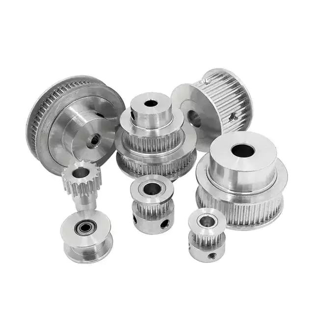
pulley basic equation
Pulleys work the same way as gravity, so they should withstand similar forces. Newton's laws of motion can be used to calculate the forces in a pulley system. The second law of motion applies to forces and accelerations. Similar to this is Newton's third law, which states that the directions of forces are equal and opposite. The fourth law dictates the direction of force. The Fifth Law states that tension is in equilibrium with gravity.
A pulley is a simple mechanism that transmits force by changing direction. They are generally considered to have negligible mass and friction, but this is only an approximation. Pulleys have different uses, from sailboats to farms and large construction cranes. In fact, they are the most versatile mechanisms in any system. Some of their most common applications and equations are listed below.
For example, consider 2 masses m. Those of mass m will be connected by pulleys. The static friction coefficient of the left stop is ms1, and the static friction coefficient of the right stop is ms2. A no-slip equation will contain multiple inequalities. If the 2 blocks are considered to be connected by a pulley, the coefficient of kinetic friction is mk. In other words, the weight of each block carries the same mass, but in the opposite direction.
Types of pulleys
A pulley is a device used to pull and push objects. Pulley systems are ropes, cables, belts or chains. The "drive pulley" is attached to the shaft and moves the driven pulley. They are available in a variety of sizes, and the larger they are, the higher the speed of power transmission. Alternatively, use small pulleys for smaller applications.
Two-wheel pulleys have 2 mechanical advantages. The greater the mechanical advantage, the less force is required to move the object. More wheels lift more weight, but smaller pulleys require less force. In a two-wheel pulley system, the rope is wound around 2 axles and a fixed surface. As you pull on the rope, the shafts above slowly come together.
Compound pulleys have 2 or more rope segments that are pulled up on the load. The mechanical advantage of compound pulleys depends on the number of rope segments and how they are arranged. This type of pulley can increase the force by changing the direction of the rope segment. There are 2 main types of pulleys. Composite pulleys are most commonly used in construction. The ideal mechanical advantage of pulleys is 2 or more.
Construction pulleys are a basic type. They are usually attached to wheel rails and can be lifted to great heights. Combinations of axes are also common. Construction pulleys can be raised to great heights to access materials or equipment. When used in construction, these pulleys are usually made of heavy materials such as wood or metal. They are secured with ropes or chains.
The ideal mechanical advantage of pulleys
The pulley system is a highly complex system with high mechanical advantages. Use a single pulley system to reduce the force required to lift an object by cutting it in half. The mechanical advantage increases as you add more pulleys, such as 6 or seven. To calculate the mechanical advantage of a pulley system, you need to count the number of rope segments between the pulleys. If the free end of the rope is facing down, don't count it. If it's facing up, count. Once you have your number, add it up.
The required mechanical advantage of a pulley is the number of rope segments it has to pull the load. The more rope segments, the lower the force. Therefore, the more rope segments the pulley has, the lower the force. If the rope segments are four, then the ideal mechanical advantage is four. In this case, the composite pulley quadrupled the load force.
The ideal mechanical advantage of a pulley system is the sum of the mechanical force and the force required to lift the load at its output. Typically, a single pulley system uses 2 ropes, and the mechanical force required to lift the load is multiplied by the 2 ropes. For a multi-pulley system, the number of ropes will vary, but the total energy requirement will remain the same. The friction between the rope and pulley increases the force and energy required to lift the load, so the mechanical advantage diminishes over time.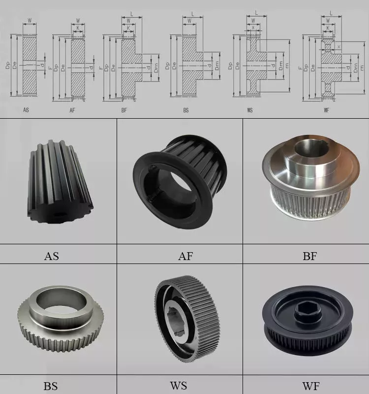
Common uses of pulley systems
A pulley system is a simple mechanical device typically used to lift heavy objects. It consists of a rotating wheel attached to a fixed shaft and a rope attached to it. When the wheel moves, the force applied by the operator is multiplied by the speed of the pulley, and the force is multiplied by the weight of the object being lifted. Common uses for pulley systems include pulling, lifting, and moving heavy objects.
The oil and petroleum industries use pulley systems in a variety of applications. Most commonly, pulleys are used in drilling operations and they are installed on top of the rig to guide the cable. The cable itself is attached to 2 pulleys suspended in the derrick, where they provide mechanical energy to the cable. Using a pulley system in this application provides the force needed to move the cable safely and smoothly.
The main advantage of the pulley system is that it minimizes the force required to lift an object. The force used to lift the object is multiplied by the desired mechanical advantage. The more rope segments, the lower the force required. On the other hand, a compound pulley system can have many segments. Therefore, a compound pulley system can increase the force a worker can exert on an object.
Safety Precautions to Take When Working on Pulley Systems
There are many safety precautions that should be observed when working on a pulley system. The first is to wear proper protective gear. This includes hard hats that protect you from falling objects. Also, gloves may be required. You should limit the amount of movement in the penalty area, and you should also keep the area free of unnecessary people and objects. Also, remember to wear a hard hat when working on the pulley system.
Another important safety precaution when working on a pulley system is to check the Safe Working Load (SWL) of the pulley before attaching anything. This will help you understand the maximum weight the pulley can hold. Also, consider the angle and height of the pulley system. Always use safety anchors and always remember to wear a hat when working on a pulley system.
Safe use of chain hoists requires training and experience. It is important to read the manufacturer's manual and follow all safety precautions. If you're not sure, you can actually inspect the hoist and look for signs of damage or tampering. Look for certifications for sprocket sets and other lifting accessories. Look for the Safe Working Load (SWL) marking on the chain hoist.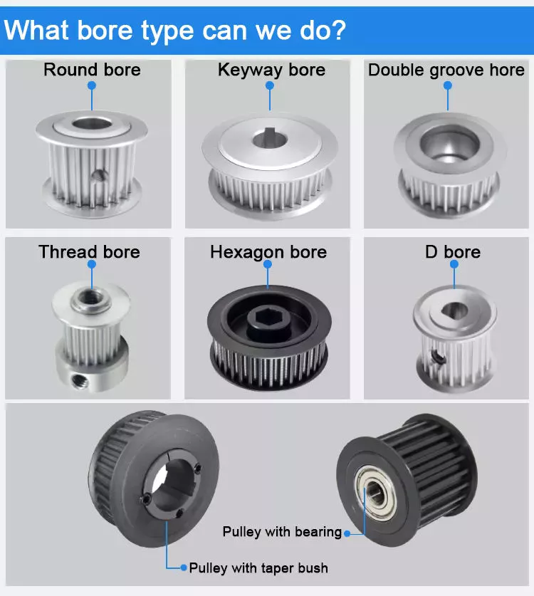
Example of a pulley system
Pulley systems are often used to lift items. It allows you to reduce the effort to lift and move the load by applying force in 1 direction. Pulley systems can be built and modeled to fit any type of project. This resource focuses on pulley systems and is designed to support the new GCSEs in Engineering, Design and Technology. There are also many examples of pulley systems suitable for various applications.
In the study, participants who read easy text took longer to manipulate the pulley system than those who read challenging text. In general, this suggests that participants with prior scientific experience used their cognitive abilities more effectively. Additionally, students who read simple texts spent less time planning the pulley system and more time on other tasks. However, the study did show that the time required to plan the pulley system was similar between the 2 groups.
In everyday life, pulley systems are used to lift various objects. Flagpoles are 1 of many pulley systems used to raise and lower flagpoles. They can also be used to raise and lower garage doors. Likewise, rock climbers use pulleys to help them ascend and descend. The pulley system can also be used to extend the ladder.
China manufacturer Telake Strong Design Four Wheel Agriculture Tractor 140HP 150HP 160HP Farm Machine with Great quality
Product Description
Product Description:TK160-180HP series tractor is designed for works on middle-scale farms and auxiliary works on large farm
land. It equips with Chinese famous supercharged engine, 6 cylinders, produces more power and less
fuel consumption, making the work more energy-efficient.
With dynamic and fashionable appearance, flat floor, side console and suspension pedal, HANWO patent
luxury cab, with A/C or heater, provide you a safe, quite and comfortable driving condition.
Standard with enhanced chassis and 16F+8R shuttle shift gearbox, optional creeper type gear shift, to
meet the requirements on more rational speeds;
Equipped with strong pressure device lifter to ensure the best rotary tillage and plowing effect. Force
control, position control or floating control is optional for different conditions.
We use category II type three-point hitch, up to international standard; enhanced lifting arms and
quick-change connectors improve the general strength while matching various implements.
Optional Herringbone tires, radial tires or other type of tires to meet your needs of working conditions;
Main Technical Specifications:
| Model | TK1504 | TK1604 | TK1804 | ||
| Type | 4×4 | 4×4 | 4×4 | ||
|
Dimensions of Tractor (mm) |
L×W×H | 5060×2300×3100 | 5280×2340×3100 | 5280×2340×3100 | |
| Tread | Front Wheel | 1612, 1712, 1952,2072 | 1612, 1712, 1952,2072 | 1612, 1712, 1952,2072 | |
| Rear Wheel | 1620~2420(usual 1800) | 1700~2300(usual 1800) | 1700~2300(usual 1800) | ||
| Wheel Base | 2510 | 2657 | 2657 | ||
| Min. Ground Base | 395 (the bottom of front axle ) | 450 (the bottom of traction plate ) | |||
| Min. Usage Mass(kg) | 5300 | 5500 | 5500 | ||
|
Engine |
Model | Weichai WP6G150E330A | Weichai WP6G160E330 | Weichai WP6G180E330 | |
| Type | Vertical, water cooled, 4-stroke, turbocharged, intercooled type | ||||
| Rated Power(kw) | 110.3 | 118 | 132.5 | ||
| Rated Rev.(r/min) | 2200 | 2200 | 2200 | ||
| Fuel | Diesel Oil | ||||
| Tire | Front Wheel | Standard 14.9-26 | |||
| Rear Wheel | Standard 18.4-38 | ||||
| Clutch | Dry-friction, Dual stage, Hydraulic power assisted | ||||
| Steering | Hydraulic type | ||||
| Transmission Box | 16F+8R Collar Shift | ||||
| Suspension Type | Post Positioned Three-point Suspension Catalogue III | ||||
| PTO | Type and Rev.(r/min) | Post-position, independent type 760/850 | |||
| Spline Size | φ38 Rectangle Spline with 8 teeth | ||||
Technology & Innovation:
WeiFang Telake has established a professional R & D team, realized the self-control ability of core components by integrating the industry's
advantageous resources, built a stable quality control system.
Invested tens millions to introduce intelligent mechanization total production line, automatic chassis production line, gearbox processing line and welding
robots, processing centers and other advanced production lines and equipment, to achieve an annual production capacity of 30,000 tractors.
/////////////////////////////////////////////////////////////////////////////////////////////////////////////////////////////////////////////////////////////////////
Packaging & Delivery:
-Delivery time:20- 30 days.
/////////////////////////////////////////////////////////////////////////////////////////////////////////////////////////////////////////////////////////////////////
Certifications:
Common problems
(1) Are you a manufacturing factory or a trading company?
We are a factory with 20 years of professional production experience in the field of 25hp-240hp tractors, located in HangZhou City, ZheJiang Province, China. Our factory has passed ISO9001, CCC, CE, SGS and BV certification. We also have a quality control department to purchase products for customers. This is why the price of our tractors is so reasonable.
(2) Can we print the logo or company name on your product or packaging?
of course. Your logo can be printed on your product by embossing, self-adhesive or silk-screen printing.
(3) About the price
The price is negotiable. It can be changed according to the options or packaging of the tractor.
(4) Regarding payment or other issues
We accept LC, TT, if you have other questions, please email me or chat with me directly.
Contact
Welcome to our factory
Adhere to the business tenet of "Integrity-based, Quality First", and wholeheartedly provide you with the best products and wholehearted service. We actively cooperate with research institutions and multinational companies to achieve continuous innovation. HangZhou Telake Agricultural Equipment CO.,LTD welcomes domestic and foreign customers to visit and guide!
HangZhou Telake Agricultural Equipment CO.,LTD
Adress: East of Xihu (West Lake) Dis. Road,South of Cailin Road,Xihu (West Lake) Dis. Economic District,HangZhou,ZheJiang ,China
What is a driveshaft and how much does it cost to replace one?
Your vehicle is made up of many moving parts. Knowing each part is important because a damaged driveshaft can seriously damage other parts of the car. You may not know how important your driveshaft is, but it's important to know if you want to fix your car. In this article, we'll discuss what a driveshaft is, what its symptoms are, and how much it costs to replace a driveshaft.
Repair damaged driveshafts
A damaged driveshaft does not allow you to turn the wheels freely. It also exposes your vehicle to higher repair costs due to damaged driveshafts. If the drive shaft breaks while the car is in motion, it may cause a crash. Also, it can significantly affect the performance of the car. If you don't fix the problem right away, you could risk more expensive repairs. If you suspect that the drive shaft is damaged, do the following.
First, make sure the drive shaft is protected from dust, moisture, and dust. A proper driveshaft cover will prevent grease from accumulating in the driveshaft, reducing the chance of further damage. The grease will also cushion the metal-to-metal contact in the constant velocity joints. For example, hitting a soft material is better than hitting a metal wall. A damaged prop shaft can not only cause difficult cornering, but it can also cause the vehicle to vibrate, which can further damage the rest of the drivetrain.
If the driveshaft is damaged, you can choose to fix it yourself or take it to a mechanic. Typically, driveshaft repairs cost around $200 to $300. Parts and labor may vary based on your vehicle type and type of repair. These parts can cost up to $600. However, if you don't have a mechanical background, it's better to leave it to a professional.
If you notice that 1 of the 2 drive shafts is worn, it's time to repair it. Worn bushings and bearings can cause the drive shaft to vibrate unnecessarily, causing it to break and cause further damage. You can also check the center bearing if there is any play in the bearing. If these symptoms occur, it is best to take your car to a mechanic as soon as possible.
Learn about U-joints
While most vehicles have at least 1 type of U-joint, there are other types available. CV joints (also known as hot rod joints) are used in a variety of applications. The minor axis is shorter than the major axis on which the U-joint is located. In both cases, the U-joints are lubricated at the factory. During servicing, the drive shaft slip joint should be lubricated.
There are 2 main styles of U-joints, including forged and press fit. They are usually held in place by C-clamps. Some of these U-joints have knurls or grooves. When selecting the correct fitting, be sure to measure the entire fitting. To make sure you get the correct size, you can use the size chart or check the manual for your specific model.
In addition to lubrication, the condition of the U-joint should be checked regularly. Lubricate them regularly to avoid premature failure. If you hear a clicking sound when shifting gears, the u-joint space may be misaligned. In this case, the bearing may need to be serviced. If there is insufficient grease in the bearings, the universal joint may need to be replaced.
U-joint is an important part of the automobile transmission shaft. Without them, your car would have no wheeled suspension. Without them, your vehicle will have a rickety front end and a wobbly rear end. Because cars can't drive on ultra-flat surfaces, they need flexible driveshafts. The U-joint compensates for this by allowing it to move up and down with the suspension.
A proper inspection will determine if your u-joints are loose or worn. It should be easy to pull them out. Make sure not to pull them all the way out. Also, the bearing caps should not move. Any signs of roughness or wear would indicate a need for a new UJ. Also, it is important to note that worn UJs cannot be repaired.
Symptoms of Driveshaft Failure
One of the most common problems associated with a faulty driveshaft is difficulty turning the wheels. This severely limits your overall control over the vehicle. Fortunately, there are several symptoms that could indicate that your driveshaft is failing. You should take immediate steps to determine the cause of the problem. One of the most common causes of driveshaft failure is a weak or faulty reverse gear. Other common causes of driveshaft damage include driving too hard, getting stuck in reverse gear and differential lock.
Another sign of a failed driveshaft is unusual noise while driving. These noises are usually the result of wear on the bushings and bearings that support the drive shaft. They can also cause your car to screech or scratch when switching from drive to idle. Depending on the speed, the noise may be accompanied by vibration. When this happens, it's time to send your vehicle in for a driveshaft replacement.
One of the most common symptoms of driveshaft failure is noticeable jitter when accelerating. This could be a sign of a loose U-joint or worn center bearing. You should thoroughly inspect your car to determine the cause of these sounds and corresponding symptoms. A certified mechanic can help you determine the cause of the noise. A damaged propshaft can severely limit the drivability of the vehicle.
Regular inspection of the drive shaft can prevent serious damage. Depending on the damage, you can replace the driveshaft for anywhere from $500 to $1,000. Depending on the severity of the damage and the level of repair, the cost will depend on the number of parts that need to be replaced. Do not drive with a bad driveshaft as it can cause a serious crash. There are several ways to avoid this problem entirely.
The first symptom to look for is a worn U-joint. If the U-joint comes loose or moves too much when trying to turn the steering wheel, the driveshaft is faulty. If you see visible rust on the bearing cap seals, you can take your car to a mechanic for a thorough inspection. A worn u-joint can also indicate a problem with the transmission.
The cost of replacing the drive shaft
Depending on your state and service center, a driveshaft repair can cost as little as $300 or as high as $2,000, depending on the specifics of your car. Labor costs are usually around $70. Prices for the parts themselves range from $400 to $600. Labor costs also vary by model and vehicle make. Ultimately, the decision to repair or replace the driveshaft will depend on whether you need a quick car repair or a full car repair.
Some cars have 2 separate driveshafts. One goes to the front and the other goes to the back. If your car has 4 wheel drive, you will have two. If you're replacing the axles of an all-wheel-drive car, you'll need a special part for each axle. Choosing the wrong 1 can result in more expensive repairs. Before you start shopping, you should know exactly how much it will cost.
Depending on the type of vehicle you own, a driveshaft replacement will cost between PS250 and PS500. Luxury cars can cost as much as PS400. However, for safety and the overall performance of the car, replacing the driveshaft may be a necessary repair. The cost of replacing a driveshaft depends on how long your car has been on the road and how much wear and tear it has experienced. There are some symptoms that indicate a faulty drive shaft and you should take immediate action.
Repairs can be expensive, so it's best to hire a mechanic with experience in the field. You'll be spending hundreds of dollars a month, but you'll have peace of mind knowing the job will be done right. Remember that you may want to ask a friend or family member to help you. Depending on the make and model of your car, replacing the driveshaft is more expensive than replacing the parts and doing it yourself.
If you suspect that your drive shaft is damaged, be sure to fix it as soon as possible. It is not advisable to drive a car with abnormal vibration and sound for a long time. Fortunately, there are some quick ways to fix the problem and avoid costly repairs later. If you've noticed the symptoms above, it's worth getting the job done. There are many signs that your driveshaft may need service, including lack of power or difficulty moving the vehicle.