Product Description
Products Description
|
Product Name |
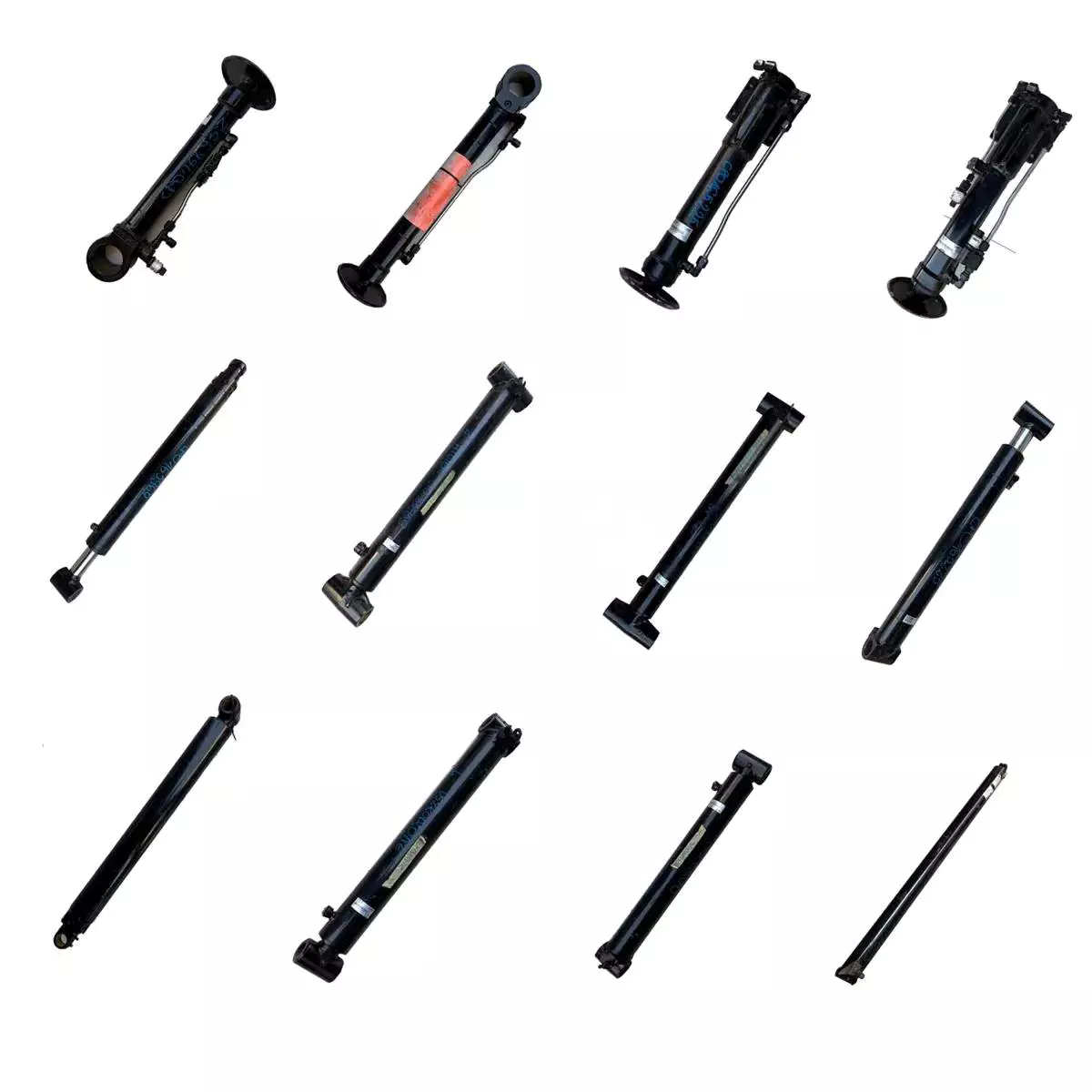
HSG Series Hydraulic Cylinder |
|||
|
Work Press |
7/14/16/21/31.5MPa 37.5/63MPa Can be Customized |
|||
|
Material |
Aluminum,Cast Iron,45mnb Steel,Stainless Steel |
|||
|
Bore Size |
40mm--320mm,Customizable |
|||
|
Shaft Diameter |
20mm--220mm,Customizable |
|||
|
Stroke Length |
30mm--14100mm,Customizable |
|||
|
Rod Surface Hardness |
HRC48-54 |
|||
|
Paint Color |
Black,Yellow,Blue,Brown,Customizable |
|||
|
Mounting |
Earring,Flange,Clevis.Foot,Trunnion,Customizable |
|||
|
Warrenty |
1 Year |
|||
|
MOQ |
1 Piece |
|||
|
Delivery Time |
7-15 Days,Also depands on specific demands |
|||
|
Certification |
ISO9001,CE |
|||
Company Profile
QIANGLIN HYDRAULIC MACHINERY CO., LTD
| QiangLin is a professional hydraulic equipment manufacturer, mainly engaged in hydraulic system design, manufacture, installation, transformation, sales, and technical services. Our manufacturing facilities are certified to the ISO 9001 standard. We are an approved supplier to many equipment manufacturers in China. We are also partners with many customers from America, Canada, Australia, Germany, England, and other European Countries. Product quality, shorter delivery time, and customer satisfaction are our long-term commitments to our CHINAMFG customers. Hope to be your partner. |
FAQ:
Q1: Are you a trading company or a manufacturer?
A: We have our own factory.
Q2: Are you able to make Non-standard or customized products?
A: Yes, we can.
Q3: How long is your delivery time?
A: Normally, the delivery time is 7 days if we have stock, 15-30 working days if we don't. but it
also depends on the product
requirements and quantity.
Q4: Do you provide samples? are the samples free or not?
A: Yes, we can provide samples, but they are not free of charge.
Q5: What are your payment terms?
A: 30% deposit T/T or Irrevocable L/C at sight, If you have any questions, please feel free to
contact us.
Q6: What are your After-sales services?
A: Before shipment, Each individual product will be strictly inspected on our factory QC Process
System. In addition, We have a
Customer Service team to respond to customers' questions within 12 hours. Being helpful in
solving customers' problems is always our goal.
| Certification: | CE, ISO9001 |
|---|---|
| Pressure: | High Pressure |
| Work Temperature: | Normal Temperature |
| Customization: |
Available
|
|
|---|
.shipping-cost-tm .tm-status-off{background: none;padding:0;color: #1470cc}
|
Shipping Cost:
Estimated freight per unit. |
about shipping cost and estimated delivery time. |
|---|
| Payment Method: |
|
|---|---|
|
Initial Payment Full Payment |
| Currency: | US$ |
|---|
| Return&refunds: | You can apply for a refund up to 30 days after receipt of the products. |
|---|
What advancements in hydraulic cylinder technology have improved sealing and reliability?
Advancements in hydraulic cylinder technology have continuously contributed to improving sealing and reliability in hydraulic systems. These advancements aim to address common challenges such as leakage, wear, and failure of seals, ensuring optimal performance and longevity. Here are several key advancements that have significantly improved sealing and reliability in hydraulic cylinders:
1. High-Performance Sealing Materials:
- The development of advanced sealing materials has greatly improved the sealing capabilities of hydraulic cylinders. Traditional sealing materials like rubber have been replaced or enhanced with high-performance materials such as polyurethane, PTFE (polytetrafluoroethylene), and various composite materials. These materials offer superior resistance to wear, temperature, and chemical degradation, resulting in improved sealing performance and extended seal life.
2. Enhanced Seal Designs:
- Advancements in seal designs have focused on improving sealing efficiency and reliability. Innovative seal profiles, such as lip seals, wipers, and scrapers, have been developed to optimize fluid retention and prevent contamination. These designs provide better sealing performance, minimizing the risk of fluid leakage and maintaining system integrity. Additionally, improved seal geometries and manufacturing techniques ensure tighter tolerances, reducing the potential for seal failure due to misalignment or extrusion.
3. Integrated Seal and Bearing Systems:
- Hydraulic cylinders now incorporate integrated seal and bearing systems, where the sealing elements also serve as bearing surfaces. This design approach reduces the number of components and potential failure points, improving overall reliability. By integrating seals and bearings, the risk of seal damage or displacement due to excessive loads or misalignment is minimized, resulting in enhanced sealing performance and increased reliability.
4. Advanced Coatings and Surface Treatments:
- The application of advanced coatings and surface treatments to hydraulic cylinder components has significantly improved sealing and reliability. Coatings such as chrome plating or ceramic coatings enhance surface hardness, wear resistance, and corrosion resistance. These surface treatments provide a smoother and more durable surface for seals to operate against, reducing friction and improving sealing performance. Moreover, specialized coatings can also provide self-lubricating properties, reducing the need for additional lubrication and enhancing reliability.
5. Sealing System Monitoring and Diagnostic Technologies:
- The integration of monitoring and diagnostic technologies in hydraulic systems has revolutionized seal performance and reliability. Sensors and monitoring systems can detect and alert operators to potential seal failures or leaks before they escalate. Real-time monitoring of pressure, temperature, and seal performance parameters allows for proactive maintenance and early intervention, preventing costly downtime and ensuring optimal sealing and reliability.
6. Computational Modeling and Simulation:
- Computational modeling and simulation techniques have played a significant role in advancing hydraulic cylinder sealing and reliability. These tools enable engineers to analyze and optimize seal designs, fluid flow dynamics, and contact stresses. By simulating various operating conditions, potential issues such as seal extrusion, wear, or leakage can be identified and mitigated early in the design phase, resulting in improved sealing performance and enhanced reliability.
7. Systematic Maintenance Practices:
- Advances in hydraulic cylinder technology have also emphasized the importance of systematic maintenance practices to ensure sealing and overall system reliability. Regular inspection, lubrication, and replacement of seals, as well as routine system flushing and filtration, help prevent premature seal failure and optimize sealing performance. Implementing preventive maintenance schedules and adhering to recommended service intervals contribute to extended seal life and enhanced reliability.
In summary, advancements in hydraulic cylinder technology have led to significant improvements in sealing and reliability. High-performance sealing materials, enhanced seal designs, integrated seal and bearing systems, advanced coatings and surface treatments, sealing system monitoring and diagnostics, computational modeling and simulation, and systematic maintenance practices have all played key roles in achieving optimal sealing performance and increased reliability. These advancements have resulted in more efficient and dependable hydraulic systems, minimizing leakage, wear, and failure of seals, and ultimately improving the overall performance and longevity of hydraulic cylinders in diverse applications.
Ensuring Stable Performance of Hydraulic Cylinders Under Fluctuating Loads
Hydraulic cylinders are designed to provide stable performance even under fluctuating loads. They achieve this through various mechanisms and features that allow for efficient load control and compensation. Let's explore how hydraulic cylinders ensure stable performance under fluctuating loads:
- Piston Design: The piston inside the hydraulic cylinder plays a crucial role in load control. It is typically equipped with seals and rings that prevent leakage of hydraulic fluid and ensure effective transfer of force. The piston design may incorporate features such as stepped or tandem pistons, which provide enhanced load-bearing capabilities and improved stability by distributing the load across multiple surfaces.
- Cylinder Cushioning: Hydraulic cylinders often incorporate cushioning mechanisms to minimize the impact and shock caused by fluctuating loads. Cushioning can be achieved through various methods, such as adjustable cushion screws, hydraulic cushioning valves, or elastomeric cushioning rings. These mechanisms slow down the piston's movement near the end of the stroke, reducing the impact and preventing sudden stops that could lead to instability.
- Pressure Compensation: Fluctuating loads can result in pressure variations within the hydraulic system. To ensure stable performance, hydraulic cylinders are equipped with pressure compensation mechanisms. These mechanisms maintain a consistent pressure level in the system, regardless of load changes. Pressure compensation can be achieved through the use of pressure relief valves, compensating pistons, or pressure-compensated flow control valves.
- Flow Control: Hydraulic cylinders often incorporate flow control valves to regulate the speed of the cylinder's movement. By controlling the flow rate of hydraulic fluid, the cylinder's motion can be adjusted to match the changing load conditions. Flow control valves allow for smooth and controlled movement, preventing abrupt changes that could lead to instability.
- Feedback Systems: To ensure stable performance under fluctuating loads, hydraulic cylinders can be integrated with feedback systems. These systems provide real-time information on the cylinder's position, velocity, and force. By continuously monitoring these parameters, the hydraulic system can make immediate adjustments to maintain stability and compensate for load fluctuations. Feedback systems can include position sensors, pressure sensors, or load sensors, depending on the specific application.
- Proper Sizing and Selection: Ensuring stable performance under fluctuating loads starts with proper sizing and selection of hydraulic cylinders. It is crucial to choose cylinders with appropriate bore size, rod diameter, and stroke length to match the anticipated load conditions. Oversized or undersized cylinders can lead to instability and reduced performance. Proper sizing also involves considering factors such as the required force, speed, and duty cycle of the application.
In summary, hydraulic cylinders ensure stable performance under fluctuating loads through features such as piston design, cushioning mechanisms, pressure compensation, flow control, feedback systems, and proper sizing and selection. These mechanisms and considerations allow hydraulic cylinders to provide consistent and controlled movement, even in dynamic load conditions, resulting in reliable and stable performance.
What safety precautions should be followed when working with hydraulic cylinders?
Working with hydraulic cylinders requires strict adherence to safety precautions to prevent accidents, injuries, and damage to equipment or property. Hydraulic systems operate under high pressures and involve moving parts, which can pose serious hazards if not handled properly. Here's a detailed explanation of the safety precautions that should be followed when working with hydraulic cylinders:
1. Training and Knowledge:
- Ensure that personnel working with hydraulic cylinders have received adequate training and possess a thorough understanding of hydraulic system operation, maintenance, and safety protocols. Proper training should cover topics such as hydraulic principles, pressure ratings, safe work practices, and emergency procedures. Only trained and authorized personnel should be allowed to handle hydraulic cylinders.
2. Wear Personal Protective Equipment (PPE):
- Always wear appropriate personal protective equipment when working with hydraulic cylinders. This may include safety glasses, gloves, protective clothing, and steel-toed boots. PPE helps protect against potential hazards, such as hydraulic fluid leaks, flying debris, or accidental contact with moving parts.
3. Hydraulic System Inspection:
- Before working with hydraulic cylinders, inspect the entire hydraulic system for any signs of damage, leaks, or loose connections. Check hydraulic hoses, fittings, valves, and cylinders for integrity and secure fastening. If any issues are detected, the system should be repaired or serviced before operation.
4. Relieve Pressure:
- Before performing any maintenance or disassembly on a hydraulic cylinder, it is crucial to relieve the pressure in the system. Follow the manufacturer's instructions to properly release pressure and ensure that the hydraulic cylinder is depressurized before starting any work. Failure to do so can result in sudden and uncontrolled movement of the cylinder or hydraulic lines, leading to serious injuries.
5. Lockout/Tagout Procedures:
- Implement lockout/tagout procedures to prevent accidental energization of the hydraulic system while maintenance or repair work is being conducted. Lockout/tagout involves isolating the energy source, such as shutting off the hydraulic pump and locking or tagging the controls to prevent unauthorized operation. This procedure ensures that the hydraulic cylinder remains in a safe, non-operational state during maintenance activities.
6. Use Proper Lifting Techniques:
- When working with heavy hydraulic cylinders or components, use proper lifting techniques and equipment to avoid strain or injury. Hydraulic cylinders can be heavy and awkward to handle, so ensure that lifting equipment, such as cranes or hoists, is properly rated and used correctly. Follow safe lifting practices, including securing the load and maintaining a stable lifting posture.
7. Hydraulic Fluid Handling:
- Handle hydraulic fluid with care and follow proper procedures for fluid filling, transfer, and disposal. Avoid contact with the skin or eyes, as hydraulic fluid may be hazardous. Use appropriate containers and equipment to prevent spills or leaks. If any hydraulic fluid comes into contact with the skin or eyes, rinse thoroughly with water and seek medical attention if necessary.
8. Regular Maintenance:
- Perform regular maintenance and inspections on hydraulic cylinders to ensure their safe and reliable operation. This includes checking for leaks, inspecting seals, monitoring fluid levels, and conducting periodic servicing as recommended by the manufacturer. Proper maintenance helps prevent unexpected failures and ensures the continued safe use of hydraulic cylinders.
9. Follow Manufacturer Guidelines:
- Always follow the manufacturer's guidelines, instructions, and recommendations for the specific hydraulic cylinders and equipment being used. Manufacturers provide important safety information, maintenance schedules, and operational guidelines that should be strictly adhered to for safe and optimal performance.
10. Emergency Preparedness:
- Be prepared for potential emergencies by having appropriate safety equipment, such as fire extinguishers, first aid kits, and emergency eyewash stations, readily available. Establish clear communication channels and emergency response procedures to promptly address any accidents, leaks, or injuries that may occur during hydraulic cylinder operations.
By following these safety precautions, individuals working with hydraulic cylinders can minimize the risk of accidents, injuries, and property damage. It is essential to prioritize safety, maintain awareness of potential hazards, and ensure compliance with relevant safety regulations and industry standards.


editor by CX 2023-11-09
China Custom Hydraulic Cylinder for Agricultural Trailer Power Tractor Steering Telescopic Tie Rod Frame Machine Hydraulic Cylinder with Good quality
Product Description
Products Description
|
Product Name |
HSG Series Hydraulic Cylinder |
|||
|
Work Press |
7/14/16/21/31.5MPa 37.5/63MPa Can be Customized |
|||
|
Material |
Aluminum,Cast Iron,45mnb Steel,Stainless Steel |
|||
|
Bore Size |
40mm--320mm,Customizable |
|||
|
Shaft Diameter |
20mm--220mm,Customizable |
|||
|
Stroke Length |
30mm--14100mm,Customizable |
|||
|
Rod Surface Hardness |
HRC48-54 |
|||
|
Paint Color |
Black,Yellow,Blue,Brown,Customizable |
|||
|
Mounting |
Earring,Flange,Clevis.Foot,Trunnion,Customizable |
|||
|
Warrenty |
1 Year |
|||
|
MOQ |
1 Piece |
|||
|
Delivery Time |
7-15 Days,Also depands on specific demands |
|||
|
Certification |
ISO9001,CE |
|||
Company Profile
QIANGLIN HYDRAULIC MACHINERY CO., LTD
| QiangLin is a professional hydraulic equipment manufacturer, mainly engaged in hydraulic system design, manufacture, installation, transformation, sales, and technical services. Our manufacturing facilities are certified to the ISO 9001 standard. We are an approved supplier to many equipment manufacturers in China. We are also partners with many customers from America, Canada, Australia, Germany, England, and other European Countries. Product quality, shorter delivery time, and customer satisfaction are our long-term commitments to our CHINAMFG customers. Hope to be your partner. |
FAQ:
Q1: Are you a trading company or a manufacturer?
A: We have our own factory.
Q2: Are you able to make Non-standard or customized products?
A: Yes, we can.
Q3: How long is your delivery time?
A: Normally, the delivery time is 7 days if we have stock, 15-30 working days if we don't. but it
also depends on the product
requirements and quantity.
Q4: Do you provide samples? are the samples free or not?
A: Yes, we can provide samples, but they are not free of charge.
Q5: What are your payment terms?
A: 30% deposit T/T or Irrevocable L/C at sight, If you have any questions, please feel free to
contact us.
Q6: What are your After-sales services?
A: Before shipment, Each individual product will be strictly inspected on our factory QC Process
System. In addition, We have a
Customer Service team to respond to customers' questions within 12 hours. Being helpful in
solving customers' problems is always our goal.
| Certification: | CE, ISO9001 |
|---|---|
| Pressure: | High Pressure |
| Work Temperature: | Normal Temperature |
| Customization: |
Available
|
|
|---|
.shipping-cost-tm .tm-status-off{background: none;padding:0;color: #1470cc}
|
Shipping Cost:
Estimated freight per unit. |
about shipping cost and estimated delivery time. |
|---|
| Payment Method: |
|
|---|---|
|
Initial Payment Full Payment |
| Currency: | US$ |
|---|
| Return&refunds: | You can apply for a refund up to 30 days after receipt of the products. |
|---|
How do manufacturers ensure the durability and reliability of hydraulic cylinders?
Manufacturers employ various strategies and techniques to ensure the durability and reliability of hydraulic cylinders. These measures are crucial as hydraulic cylinders are often subjected to demanding operating conditions and heavy loads. To ensure their longevity and dependable performance, manufacturers focus on the following aspects:
1. High-Quality Materials:
- Manufacturers use high-quality materials in the construction of hydraulic cylinders. Components such as cylinder barrels, piston rods, seals, and bearings are made from materials that possess excellent strength, corrosion resistance, and wear resistance properties. Common materials used include high-grade steel alloys, chrome-plated rods, and specialized coatings. The selection of appropriate materials ensures that hydraulic cylinders can withstand the stresses, pressures, and environmental conditions they encounter during operation.
2. Robust Design:
- Hydraulic cylinders are designed to withstand high loads and harsh operating conditions. Manufacturers use computer-aided design (CAD) software and finite element analysis (FEA) techniques to optimize the cylinder's structural integrity and performance. The design includes factors such as proper wall thickness, reinforcement in critical areas, and appropriate sizing of components. Robust design practices ensure that hydraulic cylinders can withstand the forces and stresses they encounter, preventing premature failure and ensuring durability.
3. Quality Manufacturing Processes:
- Manufacturers follow stringent quality control measures during the manufacturing processes of hydraulic cylinders. These processes include precision machining, welding, heat treatment, and surface finishing. Skilled technicians and advanced machinery are employed to ensure dimensional accuracy, proper fitment of components, and overall quality. By adhering to strict manufacturing processes and quality standards, manufacturers can produce hydraulic cylinders with consistent performance and reliability.
4. Sealing Technology:
- The sealing system of hydraulic cylinders is critical for their durability and reliability. Manufacturers utilize advanced sealing technologies such as lip seals, O-rings, and composite seals to prevent fluid leakage and ingress of contaminants. Properly designed and high-quality seals ensure that hydraulic cylinders can maintain their performance over extended periods. Seals are tested for their compatibility with the hydraulic fluid, pressure resistance, and resilience to environmental factors such as temperature and humidity.
5. Performance Testing:
- Manufacturers subject hydraulic cylinders to rigorous performance testing to validate their durability and reliability. These tests simulate real-world operating conditions and evaluate factors such as load capacity, pressure resistance, fatigue life, and leakage. Performance testing helps identify any design flaws or weaknesses in the hydraulic cylinder and allows manufacturers to make necessary improvements. By conducting thorough performance testing, manufacturers can ensure that hydraulic cylinders meet or exceed the required performance standards.
6. Compliance with Industry Standards:
- Manufacturers adhere to industry standards and regulations to ensure the durability and reliability of hydraulic cylinders. These standards, such as ISO 6020/6022 and NFPA T3.6.7, provide guidelines for design, manufacturing, and performance requirements. By following these standards, manufacturers ensure that hydraulic cylinders are designed and built to meet specific quality and safety criteria. Compliance with industry standards helps establish a baseline for durability and reliability and instills confidence in the performance of hydraulic cylinders.
7. Regular Maintenance and Service:
- Manufacturers provide recommendations for regular maintenance and service of hydraulic cylinders. This includes guidelines for lubrication, inspection of components, and replacement of wear parts such as seals and bearings. Following the manufacturer's maintenance guidelines helps ensure the long-term durability and reliability of hydraulic cylinders. Regular maintenance also allows for the early detection of potential issues, preventing major failures and extending the service life of the hydraulic cylinders.
8. Customer Support and Warranty:
- Manufacturers provide customer support and warranty services to address any issues that arise with hydraulic cylinders. They offer technical assistance, troubleshooting guidance, and replacement of defective components. The warranty ensures that customers receive reliable and durable hydraulic cylinders and provides recourse in case of any manufacturing defects or premature failures. Strong customer support and warranty policies reflect the manufacturer's commitment to the durability and reliability of their products.
In summary, manufacturers ensure the durability and reliability of hydraulic cylinders through the use of high-quality materials, robust design practices, stringent manufacturing processes, advanced sealing technology, thorough performance testing, compliance with industry standards, regular maintenance guidelines, and customer support with warranty services. By focusing on these aspects, manufacturers can produce hydraulic cylinders that can withstand demanding conditions, provide long service life, and deliver reliable performance in various applications.
Handling the Challenges of Minimizing Fluid Leaks and Contamination in Hydraulic Cylinders
Hydraulic cylinders face challenges when it comes to minimizing fluid leaks and contamination, as these issues can impact the performance, reliability, and lifespan of the system. However, there are several measures and design considerations that help address these challenges effectively. Let's explore how hydraulic cylinders handle the challenges of minimizing fluid leaks and contamination:
- Sealing Systems: Hydraulic cylinders employ advanced sealing systems to prevent fluid leaks. These systems typically include various types of seals, such as piston seals, rod seals, and wiper seals. The seals are designed to create a tight and reliable barrier between the moving components of the cylinder and the external environment, minimizing the risk of fluid leakage.
- Seal Material Selection: The choice of seal materials is crucial in minimizing fluid leaks and contamination. Hydraulic cylinder manufacturers carefully select seal materials that are compatible with the hydraulic fluid used and resistant to wear, abrasion, and chemical degradation. This ensures the longevity and effectiveness of the seals, reducing the likelihood of leaks or premature seal failure.
- Proper Installation and Maintenance: Ensuring proper installation and regular maintenance of hydraulic cylinders is essential for minimizing fluid leaks and contamination. During installation, attention should be given to proper alignment, torqueing of bolts, and adherence to recommended procedures. Regular maintenance includes inspecting seals, replacing worn-out components, and addressing any signs of leakage promptly. Proper maintenance practices help identify and rectify issues before they escalate and cause significant problems.
- Contamination Control: Hydraulic cylinders incorporate measures to control contamination and maintain fluid cleanliness. This includes the use of filtration systems, such as in-line filters, to remove particles and contaminants from the hydraulic fluid. Additionally, hydraulic reservoirs often have breathers and desiccant filters to prevent moisture and airborne contaminants from entering the system. By controlling contamination, hydraulic cylinders minimize the risk of damage to internal components and maintain optimal system performance.
- Environmental Protection: Hydraulic cylinders may be equipped with protective features to safeguard against external contaminants. For example, bellows or protective boots can be installed to shield the rod and seals from debris, dirt, or moisture present in the operating environment. These protective measures help extend the life of the seals and enhance the overall reliability of the hydraulic cylinder.
In summary, hydraulic cylinders employ sealing systems, appropriate seal materials, proper installation and maintenance practices, contamination control measures, and environmental protection features to handle the challenges of minimizing fluid leaks and contamination. By implementing these measures, manufacturers can ensure reliable and long-lasting hydraulic cylinder performance, minimize the risk of fluid leakage, and maintain the cleanliness of the hydraulic system.
How do hydraulic cylinders handle variations in load, pressure, and speed?
Hydraulic cylinders are designed to handle variations in load, pressure, and speed effectively. They incorporate features and components that allow them to adapt to changing operating conditions and maintain optimal performance. Here's a detailed explanation of how hydraulic cylinders handle variations in load, pressure, and speed:
Variations in Load:
- Hydraulic cylinders are capable of handling variations in load by adjusting the force they exert. The force output of a hydraulic cylinder is determined by the hydraulic pressure and the surface area of the piston. When the load increases, the pressure in the hydraulic system can be adjusted to generate a higher force. This adjustment can be achieved by regulating the flow of hydraulic fluid into the cylinder using control valves. By controlling the pressure and flow, hydraulic cylinders can adapt to different load requirements, ensuring that the force applied is sufficient to handle the load while preventing excessive force that could cause damage.
Variations in Pressure:
- Hydraulic cylinders are designed to handle variations in pressure within the hydraulic system. They are equipped with seals and other components that can withstand high-pressure conditions. When the pressure within the hydraulic system fluctuates, the hydraulic cylinder adjusts accordingly to maintain its performance. The seals prevent fluid leakage and ensure that the hydraulic pressure is effectively transmitted to the piston, allowing the cylinder to generate the required force. Additionally, hydraulic systems often incorporate pressure relief valves and other safety mechanisms to protect the cylinder and the entire system from overpressure conditions.
Variations in Speed:
- Hydraulic cylinders can handle variations in speed through the control of hydraulic fluid flow. The speed of a hydraulic cylinder's extension or retraction is determined by the rate at which hydraulic fluid enters or exits the cylinder. By adjusting the flow rate using flow control valves, the speed of the cylinder's movement can be regulated. This allows for precise control over the speed, enabling operators to adapt to varying speed requirements based on the specific task or load. Furthermore, hydraulic systems can incorporate flow control valves with adjustable orifice sizes to fine-tune the speed of the cylinder's movement.
Load-Sensing Technology:
- Advanced hydraulic systems may incorporate load-sensing technology to further enhance the ability of hydraulic cylinders to handle variations in load, pressure, and speed. Load-sensing systems monitor the load demand and adjust the hydraulic pressure and flow accordingly to meet that demand. This technology ensures that the hydraulic cylinder provides the necessary force while optimizing energy efficiency. Load-sensing systems are particularly beneficial in applications where the load requirements can vary significantly, allowing hydraulic cylinders to adapt in real-time and maintain precise control over force and speed.
Accumulators:
- Hydraulic systems can also utilize accumulators to assist in handling variations in load, pressure, and speed. Accumulators store hydraulic fluid under pressure, which can be released when needed to supplement the flow and pressure in the system. When there are sudden increases in load or pressure demands, accumulators can provide additional fluid to the hydraulic cylinder, ensuring smooth operation and preventing pressure drops. Similarly, accumulators can assist in maintaining consistent speed by compensating for fluctuations in flow rate. They act as a supplemental energy source, helping hydraulic cylinders respond effectively to variations in operating conditions.
In summary, hydraulic cylinders handle variations in load, pressure, and speed through various mechanisms and components. They can adjust the force output to accommodate different load requirements by regulating hydraulic pressure. The seals and components within hydraulic cylinders allow them to withstand variations in pressure within the hydraulic system. By controlling the flow of hydraulic fluid, hydraulic cylinders can regulate the speed of their movement. Advanced technologies such as load-sensing systems and the use of accumulators further enhance the adaptability of hydraulic cylinders to changing operating conditions. These features and mechanisms enable hydraulic cylinders to maintain optimal performance and provide reliable force and motion control in a wide range of applications.
editor by CX 2023-11-06
China Professional Highest Selling Tractor Pto Shaft Cover for Agricultural Machine Tractor
Product Description
Highest selling Tractor Pto Shaft Cover for Agricultural Machine Tractor
1. Tubes or Pipes
We've already got Triangular profile tube and Lemon profile tube for all the series we provide.
And we have some star tube, splined tube and other profile tubes required by our customers (for a certain series). (Please notice that our catalog doesnt contain all the items we produce)
If you want tubes other than triangular or lemon, please provide drawings or pictures.
2.End yokes
We've got several types of quick release yokes and plain bore yoke. I will suggest the usual type for your reference.
You can also send drawings or pictures to us if you cannot find your item in our catalog.
3. Safety devices or clutches
I will attach the details of safety devices for your reference. We've already have Free wheel (RA), Ratchet torque limiter(SA), Shear bolt torque limiter(SB), 3types of friction torque limiter (FF,FFS,FCS) and overrunning couplers(adapters) (FAS).
4.For any other more special requirements with plastic guard, connection method, color of painting, package, etc., please feel free to let me know.
Features:
1. We have been specialized in designing, manufacturing drive shaft, steering coupler shaft, universal joints, which have exported to the USA, Europe, Australia etc for years
2. Application to all kinds of general mechanical situation
3. Our products are of high intensity and rigidity.
4. Heat resistant & Acid resistant
5. OEM orders are welcomed
Our factory is a leading manufacturer of PTO shaft yoke and universal joint.
We manufacture high quality PTO yokes for various vehicles, construction machinery and equipment. All products are constructed with rotating lighter.
We are currently exporting our products throughout the world, especially to North America, South America, Europe, and Russia. If you are interested in any item, please do not hesitate to contact us. We are looking CHINAMFG to becoming your suppliers in the near future.
|
Shipping Cost:
Estimated freight per unit. |
To be negotiated |
|---|
| Type: | Fork |
|---|---|
| Usage: | Agricultural Products Processing, Farmland Infrastructure, Tillage, Harvester, Planting and Fertilization, Grain Threshing, Cleaning and Drying |
| Material: | Carbon Steel |
| Customization: |
Available
| Customized Request |
|---|

How do PTO shafts handle variations in length and connection methods?
PTO (Power Take-Off) shafts are designed to handle variations in length and connection methods to accommodate different equipment setups and ensure efficient power transfer. PTO shafts need to be adjustable in length to bridge the distance between the power source and the driven machinery. Additionally, they must provide versatile connection methods to connect to a wide range of equipment. Here's a detailed explanation of how PTO shafts handle variations in length and connection methods:
1. Telescoping Design: PTO shafts often feature a telescoping design, allowing them to be adjusted in length to suit different equipment configurations. The telescoping feature enables the shaft to extend or retract, accommodating varying distances between the power source (such as a tractor or engine) and the driven machinery. By adjusting the length of the PTO shaft, it can be properly aligned and connected to ensure optimal power transfer. Telescoping PTO shafts typically consist of multiple tubular sections that slide into one another, providing flexibility in length adjustment.
2. Splined Shafts: PTO shafts commonly employ splined shafts as the primary connection method between the power source and driven machinery. Splines are a series of ridges or grooves along the shaft that interlock with corresponding grooves in the mating component. The splined connection allows for torque transfer while maintaining alignment between the power source and driven machinery. Splined shafts can handle variations in length by extending or retracting the telescoping sections while still maintaining a solid connection between the power source and the driven equipment.
3. Adjustable Sliding Yokes: PTO shafts typically feature adjustable sliding yokes on one or both ends of the shaft. These yokes allow for angular adjustment, accommodating variations in the alignment between the power source and driven machinery. The sliding yokes can be moved along the splined shaft to achieve the desired angle and maintain proper alignment. This flexibility ensures that the PTO shaft can handle length variations while ensuring efficient power transfer without placing excessive strain on the universal joints or other components.
4. Universal Joints: Universal joints are integral components of PTO shafts that allow for angular misalignment between the power source and driven machinery. They consist of a cross-shaped yoke with bearings that transmit torque between connected shafts while accommodating misalignment. Universal joints provide flexibility in connecting PTO shafts to equipment that may not be perfectly aligned. As the PTO shaft length varies, the universal joints compensate for the changes in angle, allowing for smooth power transmission even when there are variations in length or misalignment between the power source and driven machinery.
5. Coupling Mechanisms: PTO shafts utilize various coupling mechanisms to securely connect to the power source and driven machinery. These mechanisms often involve a combination of splines, bolts, locking pins, or quick-release mechanisms. The coupling methods can vary depending on the specific equipment and industry requirements. The versatility of PTO shafts allows for the use of different coupling methods, ensuring a reliable and secure connection regardless of the length variation or equipment configuration.
6. Customization Options: PTO shafts can be customized to handle specific length variations and connection methods. Manufacturers offer options to select different lengths of telescoping sections to match the specific distance between the power source and driven machinery. Additionally, PTO shafts can be tailored to accommodate various connection methods through the selection of splined shaft sizes, yoke designs, and coupling mechanisms. This customization enables PTO shafts to meet the specific requirements of different equipment setups, ensuring optimal power transfer and compatibility.
7. Safety Considerations: When handling variations in length and connection methods, it is essential to consider safety. PTO shafts incorporate protective guards and shields to prevent accidental contact with rotating components. These safety measures must be appropriately adjusted and installed to provide adequate coverage and protection, regardless of the PTO shaft's length or connection configuration. Safety guidelines and regulations should be followed to ensure the proper installation, adjustment, and use of PTO shafts in order to prevent accidents or injuries.
By incorporating telescoping designs, splined shafts, adjustable sliding yokes, universal joints, and versatile coupling mechanisms, PTO shafts can handle variations in length and connection methods. The flexibility of PTO shafts allows them to adapt to different equipment setups, ensuring efficient power transfer while maintaining alignment and safety.

How do PTO shafts handle variations in load and torque during operation?
PTO (Power Take-Off) shafts are designed to handle variations in load and torque during operation by employing specific mechanisms and features that ensure efficient power transfer and protection against overload conditions. Here's a detailed explanation of how PTO shafts handle variations in load and torque:
1. Mechanical Design: PTO shafts are engineered with robust mechanical design principles that enable them to handle variations in load and torque. They are typically constructed using high-strength materials such as steel, which provides durability and resistance to bending or twisting forces. The shaft's diameter, wall thickness, and overall dimensions are carefully calculated to withstand the expected torque levels and load variations. The mechanical design of the PTO shaft ensures that it can transmit power reliably and accommodate the dynamic forces encountered during operation.
2. Universal Joints: Universal joints are a key component of PTO shafts that allow for flexibility and compensation of misalignment between the power source and driven machinery. These joints can accommodate variations in angular alignment, which may occur due to changes in load or movement of the machinery. Universal joints consist of a cross-shaped yoke with needle bearings that allow for smooth rotation and transfer of torque, even when the shafts are not perfectly aligned. The design of universal joints enables PTO shafts to handle variations in load and torque while maintaining consistent power transmission.
3. Slip Clutches: Slip clutches are often incorporated into PTO shafts to provide overload protection. These clutches allow the PTO shaft to slip or disengage momentarily when excessive torque or resistance is encountered. Slip clutches typically consist of friction plates that can be adjusted to a specific torque setting. When the torque surpasses the predetermined limit, the clutch slips, preventing damage to the PTO shaft and connected equipment. Slip clutches are particularly useful when sudden changes in load or torque occur, providing a safety mechanism to protect the PTO shaft and associated machinery.
4. Torque Limiters: Torque limiters are another protective feature found in some PTO shafts. These devices are designed to automatically disengage the power transmission when a predetermined torque threshold is exceeded. Torque limiters can be mechanical, such as shear pin couplings or friction clutches, or electronic, utilizing sensors and control systems. When the torque exceeds the set limit, the torque limiter disengages, preventing further power transfer and protecting the PTO shaft from overload conditions. Torque limiters are effective in handling sudden spikes in torque and safeguarding the PTO shaft and associated equipment.
5. Maintenance and Inspection: Regular maintenance and inspection of PTO shafts are essential to ensure their proper functioning and ability to handle variations in load and torque. Routine maintenance includes lubrication of universal joints, inspection of shaft integrity, and tightening of fasteners. Regular inspections allow for early detection of wear, misalignment, or other issues that may affect the PTO shaft's performance. By addressing maintenance and inspection requirements, operators can identify and address any concerns that may arise due to variations in load and torque, ensuring the continued safe and efficient operation of the PTO shaft.
6. Operator Awareness and Control: Operators play a crucial role in managing variations in load and torque during PTO shaft operation. They should be aware of the machinery's operational limits, including the recommended torque ratings and load capacities of the PTO shaft. Proper training and understanding of the equipment's capabilities enable operators to make informed decisions and adjust the operation when encountering significant load or torque changes. Operators should also be vigilant in monitoring the equipment's performance, watching for any signs of excessive vibration, noise, or other indications of potential issues related to load and torque variations.
By incorporating robust mechanical design, utilizing universal joints, slip clutches, torque limiters, and implementing proper maintenance practices, PTO shafts are equipped to handle variations in load and torque during operation. These features ensure reliable power transmission, protect against overload conditions, and contribute to the safe and efficient functioning of the PTO shaft and the machinery it drives.
What is a PTO shaft and how is it used in agricultural and industrial equipment?
A power take-off (PTO) shaft is a mechanical component used in agricultural and industrial equipment to transfer power from a power source, such as an engine or motor, to another machine or implement. It is a driveline shaft that transmits rotational power and torque, allowing the connected equipment to perform various tasks. PTO shafts are commonly used in agricultural machinery, such as tractors, as well as in industrial equipment, including generators, pumps, and construction machinery. Here's a detailed explanation of what a PTO shaft is and how it is used:
Structure and Components: A typical PTO shaft consists of a hollow metal tube with universal joints at each end. The hollow tube allows the shaft to rotate freely, while the universal joints accommodate angular misalignments between the power source and the driven equipment. The universal joints consist of a cross-shaped yoke with needle bearings, providing flexibility and allowing the transmission of power at varying angles. Some PTO shafts may also include a telescopic section to adjust the length for different equipment setups or to accommodate varying distances between the power source and the driven machine.
Power Transfer: The primary function of a PTO shaft is to transfer power and torque from the power source to the driven equipment. The power source, typically an engine or motor, drives the PTO shaft through a mechanical connection, such as a gearbox or a clutch. As the power source rotates, it transmits rotational force to the PTO shaft. The PTO shaft, in turn, transfers this rotational power and torque to the driven equipment, enabling it to perform its intended function. The torque and rotational speed transmitted through the PTO shaft depend on the power source's characteristics and the gear ratio or clutch engagement.
Agricultural Applications: In agriculture, PTO shafts are commonly used in tractors to power various implements and attachments. The PTO shaft is connected to the tractor's power take-off, a rotating drive shaft located at the rear of the tractor. By engaging the PTO clutch, the tractor's engine power is transferred through the PTO shaft to the attached implements. Agricultural machinery, such as mowers, balers, tillers, sprayers, and grain augers, often rely on PTO shafts to receive power for their operation. The PTO shaft allows the implements to be powered directly by the tractor's engine, eliminating the need for separate power sources and increasing the versatility and efficiency of agricultural operations.
Industrial Applications: PTO shafts also find extensive use in various industrial applications. Industrial equipment, such as generators, pumps, compressors, and industrial mixers, often incorporate PTO shafts to receive power from engines or electric motors. The PTO shaft connects the power source to the driven equipment, allowing it to operate and perform its intended function. In construction machinery, PTO shafts can be found in equipment like concrete mixers, hydraulic hammers, and post hole diggers, enabling the transfer of power from the machinery's engine to the specific attachment or tool being used.
Safety Considerations: It is important to note that PTO shafts can pose safety risks if not handled properly. The rotating shaft can cause serious injuries if operators come into contact with it while it is in operation. To ensure safety, PTO shafts are often equipped with shielding or guards that cover the rotating shaft and universal joints, preventing accidental contact. It is crucial to maintain and inspect these safety features regularly to ensure their effectiveness. Additionally, operators should receive proper training on PTO shaft operation, including safe attachment and detachment procedures, as well as the use of personal protective equipment when working near PTO-driven machinery.
In summary, a PTO shaft is a mechanical component used in agricultural and industrial equipment to transmit power and torque from a power source to a driven machine or implement. It enables the direct power transfer from engines or motors to various equipment, increasing efficiency and versatility in agricultural and industrial operations. While PTO shafts offer significant benefits, operators must be aware of the associated safety considerations and take appropriate precautions to prevent accidents and injuries.


editor by CX 2023-09-14
China Hot selling for Farm Mini Tractors Small Pto Shaft Agricultural Sale 4X4 in Grass Machine Crawler El Salvador Petrol Engine Garden Tractor
Product Description
| Size | 260 cm * 120 cm * 135 cm |
| Drive Wheel | 4WD |
| Power | 12(Kw) |
| Specification | 30-50HP |
| Fuel | Gas / Diesel |
| Weight | 680(kg) |
| Tyres sizes | 500-12/650-16 |
| Usage | Farm Tractor, Garden Tractor, Lawn Tractor |
This is part of the certificate, please contact us if you need more!
We can provide customers with customizable packaging, a large number of goods in stock, and a wide choice of freight routes.
Q1: Can I have a sample order?
A1: Yes, we accept sample order to test and check quality.
Q2: Do you have MOQ limit?
A2: Yes, we have MOQ limit for mass production, but it depends on model. Please contact us for details.
Q3: How about the lead time?
A3: Samples will takes 5-7 business days. Mass production will takes 25-30 days. It depends on quantity.
Q4: How about shipping and delivery time?
A4: Generally, Item will be shipped via Express, such as DHL, TNT, FedEx and UPS, delivery time is 3-7 business days. Airline and sea shipping also available.
In order to better serve customers, we now make the following disclaimer for the product information published on the website that contains text, pictures, and links:
1. The product picture may have a color difference with the actual product due to the different angle and light, as well as the display difference of the monitor. The picture is for reference only, the actual product shall prevail, please contact our staff for more details.
2. It is the customized product, not final retail product. Details, description, pictures, and specifications are subject to the final confirmed order.
3. The price is for reference only, the market price is fluctuating, and the price marked on this page is not the only basis for the final transaction. Please contact our sales staff to confirm the final price.
|
Shipping Cost:
Estimated freight per unit. |
To be negotiated |
|---|
| After-sales Service: | 6 Months |
|---|---|
| Warranty: | 6 Months |
| Type: | Wheel Tractor |
| Samples: |
US$ 16999/Piece
1 Piece(Min.Order) | Order Sample |
|---|
| Customization: |
Available
| Customized Request |
|---|

How do manufacturers ensure the compatibility of PTO shafts with different equipment?
Manufacturers employ various measures to ensure the compatibility of PTO (Power Take-Off) shafts with different equipment. Compatibility is crucial to ensure that PTO shafts can effectively transfer power from the power source to the driven machinery without compromising performance, safety, or ease of use. Here's a detailed explanation of how manufacturers ensure compatibility:
1. Standardization: PTO shafts are designed and manufactured based on standardized specifications. These specifications outline the essential parameters such as shaft dimensions, spline sizes, torque ratings, and safety requirements. By adhering to standardized designs, manufacturers ensure that PTO shafts are compatible with a wide range of equipment that meets the same standards. Standardization allows for interchangeability, meaning that PTO shafts from one manufacturer can be used with equipment from another manufacturer as long as they conform to the same specifications.
2. Collaboration with Equipment Manufacturers: PTO shaft manufacturers often collaborate closely with equipment manufacturers to ensure compatibility. They work together to understand the specific requirements of the equipment and design PTO shafts that seamlessly integrate with the machinery. This collaboration may involve sharing technical specifications, conducting joint testing, and exchanging feedback. By working in partnership, manufacturers can address any compatibility issues early in the design and development process, resulting in PTO shafts that are tailored to the equipment's needs.
3. Customization Options: PTO shaft manufacturers offer customization options to accommodate different equipment configurations. They provide flexibility in terms of shaft length, spline sizes, yoke designs, and coupling mechanisms. Equipment manufacturers can specify the required parameters, and the PTO shafts can be customized accordingly. This ensures that the PTO shafts precisely match the equipment's power input/output requirements and connection methods, guaranteeing compatibility and efficient power transfer.
4. Testing and Validation: Manufacturers conduct rigorous testing and validation processes to ensure the compatibility and performance of PTO shafts. They subject the shafts to various tests, including torque testing, rotational speed testing, and durability testing. These tests verify that the PTO shafts can handle the expected power loads and operating conditions without failure. By validating the performance of the PTO shafts, manufacturers can ensure that they are compatible with a wide range of equipment and can reliably transfer power under different operating scenarios.
5. Compliance with Industry Standards: PTO shaft manufacturers adhere to industry standards and regulations to ensure compatibility. Organizations such as the American Society of Agricultural and Biological Engineers (ASABE) establish safety and performance standards for PTO shafts. Manufacturers design and produce their shafts in accordance with these standards, ensuring that their products meet the necessary requirements for compatibility and safety. Compliance with industry standards provides assurance to equipment manufacturers and end-users that the PTO shafts are compatible and suitable for use with different equipment.
6. Documentation and Guidelines: Manufacturers provide comprehensive documentation and guidelines to assist equipment manufacturers and end-users in ensuring compatibility. This documentation includes technical specifications, installation instructions, maintenance guidelines, and safety recommendations. The documentation helps equipment manufacturers select the appropriate PTO shaft for their equipment and provides guidance on proper installation and use. By following the manufacturer's guidelines, equipment manufacturers can ensure compatibility and optimize the performance of the PTO shafts.
7. Ongoing Research and Development: PTO shaft manufacturers continuously invest in research and development to enhance compatibility with different equipment. They stay updated with industry trends, technological advancements, and evolving equipment requirements. This ongoing research and development enable manufacturers to improve the design, materials, and features of PTO shafts, ensuring compatibility with the latest equipment innovations and addressing any compatibility challenges that may arise.
By employing standardization, collaborating with equipment manufacturers, offering customization options, conducting thorough testing, complying with industry standards, providing documentation and guidelines, and investing in research and development, manufacturers ensure the compatibility of PTO shafts with different equipment. This compatibility allows for seamless integration, efficient power transfer, and optimal performance across a wide range of machinery and equipment in various industries.

Can PTO shafts be customized for specific machinery and power requirements?
Yes, PTO (Power Take-Off) shafts can be customized to meet the specific machinery and power requirements of different applications. Manufacturers offer customization options to ensure that PTO shafts are precisely tailored to the power source, driven machinery, and the intended application. Here's a detailed explanation of how PTO shafts can be customized:
1. Shaft Length: PTO shafts can be customized in terms of length to accommodate different equipment configurations. The length of the PTO shaft is critical to ensure proper alignment and connection between the power source and driven machinery. Manufacturers can provide PTO shafts with adjustable or fixed-length options, allowing for flexibility in meeting specific length requirements. Customizing the shaft length ensures that the PTO shaft fits the equipment properly, optimizing power transfer efficiency and reducing the risk of misalignment or excessive stress.
2. Spline Sizes: PTO shafts are available with different spline sizes to match the input and output shafts of various equipment. Spline size customization allows the PTO shaft to seamlessly connect to the power source and driven machinery. Manufacturers can offer different spline configurations, such as 1-3/8 inch, 1-3/4 inch, or metric sizes, to accommodate specific machinery requirements. Customizing the spline size ensures a proper fit and secure connection, enabling efficient power transfer without the need for additional adapters or modifications.
3. Yoke Designs: PTO shafts can be customized with different yoke designs to match the connection points on the power source and driven machinery. The yoke is the component that attaches to the shaft and connects to the equipment. Manufacturers can provide various yoke designs, such as round, triangular, or splined yokes, to ensure compatibility with specific machinery. Customizing the yoke design allows for a secure and reliable connection, aligning the PTO shaft with the equipment's input/output shafts and optimizing power transmission efficiency.
4. Torque Ratings: PTO shafts can be customized to handle specific torque requirements based on the power demands of the application. Torque is the rotational force that the PTO shaft needs to transmit from the power source to the driven machinery. Manufacturers can design PTO shafts with different torque ratings by using appropriate materials, dimensions, and reinforcement techniques. Customizing the torque rating ensures that the PTO shaft can safely and reliably handle the required power levels without premature wear or failure.
5. Coupling Mechanisms: PTO shafts can be customized with different coupling mechanisms to match the connection requirements of specific equipment. Coupling mechanisms are the means by which the PTO shaft connects and disconnects from the power source and driven machinery. Manufacturers can provide various coupling options, such as quick-release couplings, shear pin couplings, or mechanical lock couplings, to accommodate different machinery designs and operational needs. Customizing the coupling mechanism ensures ease of use, secure attachment, and quick disengagement when necessary.
6. Protective Features: PTO shafts can be customized with additional protective features to enhance safety and durability. These features may include guard shields, safety covers, or slip clutches. Guard shields and safety covers provide physical protection by enclosing the rotating shaft and preventing accidental contact, reducing the risk of injuries. Slip clutches offer overload protection by allowing the PTO shaft to slip or disengage when excessive torque or resistance is encountered, preventing damage to the shaft and associated equipment. Customizing the protective features ensures compliance with safety regulations and addresses specific safety requirements of the machinery or application.
7. Material Selection: PTO shafts can be customized with different materials based on the application's demands. Manufacturers can offer a range of material options, such as steel, aluminum, or composite materials, with varying strength, weight, and corrosion resistance properties. Customizing the material selection allows for optimizing the PTO shaft's performance, considering factors like operating conditions, environmental exposure, and weight restrictions.
By providing customization options such as shaft length, spline sizes, yoke designs, torque ratings, coupling mechanisms, protective features, and material selection, manufacturers can ensure that PTO shafts are specifically tailored to meet the machinery and power requirements of different applications. Customized PTO shafts facilitate seamless integration, efficient power transfer, and reliable operation, enhancing the overall performance and productivity of the equipment.

Can you explain the different types of PTO shafts and their applications?
PTO shafts (Power Take-Off shafts) come in various types, each designed for specific applications and requirements. The different types of PTO shafts offer versatility and compatibility with a wide range of machinery and implements. Here's an explanation of the most common types of PTO shafts and their applications:
1. Standard PTO Shaft: The standard PTO shaft, also known as a splined shaft, is the most common type used in agricultural and industrial machinery. It consists of a solid steel shaft with splines or grooves along its length. The standard PTO shaft typically has six splines, although variations with four or eight splines can be found. This type of PTO shaft is widely used in tractors and various implements, including mowers, balers, tillers, and rotary cutters. The splines provide a secure connection between the power source and the driven machinery, ensuring efficient power transfer.
2. Shear Bolt PTO Shaft: Shear bolt PTO shafts are designed with a safety feature that allows the shaft to separate in case of overload or sudden shock to protect the driveline components. These PTO shafts incorporate a shear bolt mechanism that connects the tractor's power take-off to the driven machinery. In the event of excessive load or sudden resistance, the shear bolt is designed to break, disconnecting the PTO shaft and preventing damage to the driveline. Shear bolt PTO shafts are commonly used in equipment that may encounter sudden obstructions or high-stress situations, such as wood chippers, stump grinders, and heavy-duty rotary cutters.
3. Friction Clutch PTO Shaft: Friction clutch PTO shafts feature a clutch mechanism that allows for smooth engagement and disengagement of the power transfer. These PTO shafts typically incorporate a friction disc and a pressure plate, similar to a traditional vehicle clutch system. The friction clutch allows operators to gradually engage or disengage the power transfer, reducing shock loads and minimizing wear on the driveline components. Friction clutch PTO shafts are commonly used in applications where precise control of power engagement is required, such as in hydraulic pumps, generators, and industrial mixers.
4. Constant Velocity (CV) PTO Shaft: Constant Velocity (CV) PTO shafts, also known as homokinetic shafts, are designed to accommodate high angles of misalignment without affecting power transmission. They use a universal joint mechanism that allows for smooth power transfer even when the driven machinery is at an angle relative to the power source. CV PTO shafts are frequently used in applications where the machinery requires a significant range of movement or articulation, such as in articulated loaders, telescopic handlers, and self-propelled sprayers.
5. Telescopic PTO Shaft: Telescopic PTO shafts are adjustable in length, allowing for flexibility in equipment configuration and varying distances between the power source and the driven machinery. They consist of two or more concentric shafts that slide within each other, providing the ability to extend or retract the PTO shaft as needed. Telescopic PTO shafts are commonly used in applications where the distance between the tractor's power take-off and the implement varies, such as in front-mounted implements, snow blowers, and self-loading wagons. The telescopic design enables easy adaptation to different equipment setups and minimizes the risk of the PTO shaft dragging on the ground.
6. Gearbox PTO Shaft: Gearbox PTO shafts are designed to adapt power transmission between different rotational speeds or directions. They incorporate a gearbox mechanism that allows for speed reduction or increase, as well as the ability to change rotational direction. Gearbox PTO shafts are commonly used in applications where the driven machinery requires a different speed or rotational direction than the tractor's power take-off. Examples include grain augers, feed mixers, and industrial equipment that requires specific speed ratios or reversing capabilities.
It's important to note that the availability and specific applications of PTO shaft types may vary based on regional and industry-specific factors. Additionally, certain machinery or implements may require specialized or custom PTO shafts to meet specific requirements.
In summary, the different types of PTO shafts, such as standard, shear bolt, friction clutch, constant velocity (CV), telescopic, and gearbox shafts, offer versatility and compatibility with various machinery and implements. Each type of PTO shaft is designed to address specific needs, such as power transfer efficiency, safety, smooth engagement, misalignment tolerance, adaptability, and speed/direction adjustment. Understanding the different types of PTO shafts and their applications is crucial for selecting the appropriate shaft forthe intended machinery and ensuring optimal performance and reliability.
editor by CX 2023-09-14
China Custom Farm Machine Pto Small Tractor Tiller Cuitivator Power near me supplier
Product Description
Product Description:
| Product Name | Farm Machine PTO Small Tractor Tiller Cuitivator Power |
| Model | RT-125 |
| Color | depend on customer's choice |
| Dimension(mm) | 1460*550*560 |
| Number of blades | 28 |
| Cutting Width | 125cm |
| Tilling depth | 8-12 |
| Power Required | 20-30HP |
*Transmission: chain driven.
*Graphite gearbox is made of casting iron. Material performance is better. Not easy broken.
*The suspension plate shape is not easy to deform.
*Chain device hand adjustable. More easy and reliable.
*Side protection plates are added CZPT the rear deflection. This device prevents the soil flying out.
*The tilling height can be adjustable.
*The structure is firm and stable.
Packing & Delivery
Packing Details : Packing, wooden box for the garden tiller ,1pcs/carton
Delivery Details : 25 days after order
Our service
Best After Sales Service:
We have France Branch. CZPT Europe can give Europe customer best service.
1. CZPT Europe can send you spare parts once you need them.
2. Our machine Warranty time: 14 months. We provide free spare parts.
3. We provide lifetime repair service and spare parts. You just tell us what you want. We will give you the solution in time.
4.If the CZPT Europe cannot give you the satisfaction. The head office engineer is willing to wear the CZPT blue Uniform clothes to your site for repair.
Our Purpose:
Quality first, best service, win-win!
Welcome to visit our factory !
Welcome to send inquiry to us !
FAQ&Contact
Q: Are you trading company or manufacturer ?
A: We are factory.
Factory Address: No2.Xihu (West Lake) Dis.ng Road,TiHangZhou District,HangZhou,ZheJiang ,China
Q: How long is your delivery time?
A: Generally it is 14 months
Contact with me below:
Ms Sky
HangZhou CZPT Industary and Trade Co.,Ltd
Tel:86~/8822 0571 -88166585 Fax:86~/8822 0571 -88166595
Website: cnlefa
The Functions of Splined Shaft Bearings
Splined shafts are the most common types of bearings for machine tools. They are made of a wide variety of materials, including metals and non-metals such as Delrin and nylon. They are often fabricated to reduce deflection. The tooth profile will become deformed with time, as the shaft is used over a long period of time. Splined shafts are available in a huge range of materials and lengths.
Functions
Splined shafts are used in a variety of applications and industries. They are an effective anti-rotational device, as well as a reliable means of transmitting torque. Other types of shafts are available, including key shafts, but splines are the most convenient for transmitting torque. The following article discusses the functions of splines and why they are a superior choice. Listed below are a few examples of applications and industries in which splines are used.
Splined shafts can be of several styles, depending on the application and mechanical system in question. The differences between splined shaft styles include the design of teeth, overall strength, transfer of rotational concentricity, sliding ability, and misalignment tolerance. Listed below are a few examples of splines, as well as some of their benefits. The difference between these styles is not mutually exclusive; instead, each style has a distinct set of pros and cons.
A splined shaft is a cylindrical shaft with teeth or ridges that correspond to a specific angular position. This allows a shaft to transfer torque while maintaining angular correspondence between tracks. A splined shaft is defined as a cylindrical member with several grooves cut into its circumference. These grooves are equally spaced around the shaft and form a series of projecting keys. These features give the shaft a rounded appearance and allow it to fit perfectly into a grooved cylindrical member.
While the most common applications of splines are for shortening or extending shafts, they can also be used to secure mechanical assemblies. An "involute spline" spline has a groove that is wider than its counterparts. The result is that a splined shaft will resist separation during operation. They are an ideal choice for applications where deflection is an issue.
A spline shaft's radial torsion load distribution is equally distributed, unless a bevel gear is used. The radial torsion load is evenly distributed and will not exert significant load concentration. If the spline couplings are not aligned correctly, the spline connection can fail quickly, causing significant fretting fatigue and wear. A couple of papers discuss this issue in more detail.
Types
There are many different types of splined shafts. Each type features an evenly spaced helix of grooves on its outer surface. These grooves are either parallel or involute. Their shape allows them to be paired with gears and interchange rotary and linear motion. Splines are often cold-rolled or cut. The latter has increased strength compared to cut spines. These types of shafts are commonly used in applications requiring high strength, accuracy, and smoothness.
Another difference between internal and external splined shafts lies in the manufacturing process. The former is made of wood, while the latter is made of steel or a metal alloy. The process of manufacturing splined shafts involves cutting furrows into the surface of the material. Both processes are expensive and require expert skill. The main advantage of splined shafts is their adaptability to a wide range of applications.
In general, splined shafts are used in machinery where the rotation is transferred to an internal splined member. This member can be a gear or some other rotary device. These types of shafts are often packaged together as a hub assembly. Cleaning and lubricating are essential to the life of these components. If you're using them on a daily basis, you'll want to make sure to regularly inspect them.
Crowned splines are usually involute. The teeth of these splines form a spiral pattern. They are used for smaller diameter shafts because they add strength. Involute splines are also used on instrument drives and valve shafts. Serration standards are found in the SAE. Both kinds of splines can also contain a ball bearing for high torque. The difference between the 2 types of splines is the number of teeth on the shaft.
Internal splines have many advantages over external ones. For example, an internal spline shaft can be made using a grinding wheel instead of a CNC machine. It also uses a more accurate and economical process. Furthermore, it allows for a shorter manufacturing cycle, which is essential when splining high-speed machines. In addition, it stabilizes the relative phase between the spline and thread.
Manufacturing methods
There are several methods used to fabricate a splined shaft. Key and splined shafts are constructed from 2 separate parts that are shaped in a synchronized manner to transfer torque uniformly. Hot rolling is 1 method, while cold rolling utilizes low temperatures to form metal. Both methods enhance mechanical properties, surface finishes, and precision. The advantage of cold rolling is its cost-effectiveness.
Cold forming is 1 method, as well as machining and assembling. Cold forming is a unique process that allows the spline to be shaped to the desired shape. The resulting shape provides maximum contact area and torsional strength. Standard splines are available in standard sizes, but custom lengths can also be ordered. CZPT offers various auxiliary equipment, such as mating sleeves and flanged bushings.
Cold forging is another method. This method produces long splined shafts that are used in automobile propellers. After the spline portion is cut out, it is worked on in a hobbing machine. Work hardening enhances the root strength of the splined portion. It can be used for bearings, gears, and other mechanical components. Listed below are the manufacturing methods for splined shafts.
Parallel splines are the simplest of the splined shaft manufacturing methods. Parallel splines are usually welded to shafts, while involute splines are made of metal or non-metals. Splines are available in a wide variety of lengths and materials. The process is usually accompanied by a process called milling. The workpiece rotates to produce the serrated surface.
Splines are internal or external grooves in a splined shaft. They work in combination with keyways to transfer torque. Male and female splines are used in gears. Female and male splines correspond to 1 another to ensure proper angular correspondence. Involute splines have more surface area and thus are stronger than external splines. Moreover, they help the shaft fit into a grooved cylindrical member without misalignment.
A variety of other methods of manufacturing a splined shaft can be used to produce a splined shaft. Spline shafts can be produced using broaching and shaping, 2 precision machining methods. Broaching uses a metal tool with successively larger teeth to remove metal and create ridges and holes in the surface of a material. However, this process is expensive and requires special expertise.
Applications
The splined shaft is a mechanical component with a helix-like shape formed by the equal spacing of grooves in a circular ring. The splines can either have parallel or involute sides. The splines minimize stress concentration in stationary joints and can be used in both rotary and linear motion. In some cases, splines are rolled rather than cut. The latter is more durable than cut splines and is often used in applications requiring high strength, accuracy, and smooth finish.
Splined shafts are commonly made of carbon steel. This alloy steel has a low carbon content, making it easy to work with. Carbon steel is a great choice for splines because it is malleable. Generally, high-quality carbon steel provides a consistent motion. Steel alloys are also available that contain nickel, chromium, copper, and other metals. If you're unsure of the right material for your application, you can consult a spline chart.
Splines are a versatile mechanical component. They are easy to cut and fit. Splines can be internal or external, with teeth positioned at equal intervals on both sides of the shaft. This allows the shaft to engage with the hub around the entire circumference of the hub. It also increases load capacity by creating a constant multiple-tooth point of contact with the hub. For this reason, they're used extensively in rotary and linear motion.
Splined shafts are used in a wide variety of industries. CZPT Inc. offers custom and standard splined shafts for a variety of applications. When choosing a splined shaft for a specific application, consider the surrounding mated components, torque requirements, and size requirements. These 3 factors will make it the ideal choice for your rotary equipment. And you'll be pleased with the end result!
There are many types of splines and their applications are endless. They transfer torque and angular misalignment between parts, and they also enable the axial rotation of assembled components. Therefore, splines are an essential component of machinery and are used in a wide range of applications. This type of shaft can be found in various types of machines, from household appliances to industrial machinery. So, the next time you're looking for a splined shaft, make sure you look for a splined one.


China Custom for Dealers! ! Snow Cleaning Machine Sweeper with CE for Tractor Sale in Germany/Spain/France near me factory
Product Description
SX150 Hydraulic Snow Sweeper for Tractor Rear
We are Professional Manufacturer!!
Product Description
Main Features:
1. Compact structure, flexible attaching, easy assembling and disassembling.
2. Strengthened structure design, fast moving speed and high working efficiency.
3. PTO in a straight line under working condition, with low wear and power consumption.
4. Brush combined with PP and steel wire, good abrasion-resistance and high toughness.
5. Brush made by 1 time stamping, hardened structure, reasonable arrangement, cost saving and excellent sweeping effectiveness.
6. Brush roller connected by flange,convenient disassembling and maintenance.
The reasons for choosing it:
---Rear 3 point linked;
---Brush roller connected by flange,easy exchange;
---Belt with automatic tension;
---Replaceable Brush roller and Brush pieces;
---Fully-protected packing;
---Powerful productivity,Stable quality
Product Parameters
| Model | 3-point Hitched | SX150 | SX165 | SX180 | SX210 |
| Tractor Front Mounted | SX150-F | SX165-F | SX180-F | SX210-F | |
| Matching Tractor (hp) | 20~40 | 40~60 | 50~80 | 70~100 | |
| Valid Sweeping Width (30°) | 1500 | 1650 | 1800 | 2100 | |
| Brush Roller Length (mm) | 1740 | 1910 | 2100 | 2450 | |
| Swing Angle | 3-point Hitched | 30°(Right Direction) | |||
| Tractor Front Mounted | -30°~30°(Hydraulic Swing)(Option) | ||||
| Brush Dia. (mm) | 500 | ||||
| Roller Driven Type | 3-point Hitched | PTO Driven(1000r/min) | |||
| Tractor Front Mounted | Hydraulic Motor | ||||
| Sweeping Efficiency | 5~15km/h | ||||
Detailed Photos
3 point Hitch type:
Front Road Sweeper Type:
Other Cleaning snow machinery mounted tractor:
Snow Plow Snow Blower
Company Profile
1. ZheZheJiang nco Agricultural Equipment Technology Co., Ltd. is a state-owned holding company, which is subordinate to ZheJiang Academy of Agricultural Machinery Sciences date from 1959.
2. We design, test, build and sell Agricultural Equipment and Tractor Attachments for Farming and Forestry dealer and personal user customers.
3. Our products are Made in China and Exported to Asia, Europe, America, Australia with annual exports over 7000 sets for more than 12 years.
4.And we are proud to be close suppliers of Chinese famous tractor manufacturers and Kubota, John Deere, New Holland,etc.
FAQ
Screw Shaft Types
If you're looking for a screw shaft, but aren't sure which type to buy, you're in luck. In this article, we'll talk about the different types, including Threaded shank, Round head, and Machined. Once you've read it, you'll know which type to buy. Then, you can decide whether you want a ball screw nut or a threaded shank.
Machined screw shafts
Besides the standard stainless steel shaft, manufacturers also provide a variety of other materials, such as titanium, bronze, and brass. In addition to stainless steel, manufacturers also provide a variety of top-coating options, including zinc, brass, and chromium. Aluminum screws are not particularly durable and are easily affected by weather. Most screw shafts feature self-locking mechanisms. They are especially useful in C-clamps, vises, and screw-top container lids.
For applications where accuracy is vital, a ball screw shaft needs to be annealed. A heat treatment can be performed on the ball screw shaft to ensure that both ends are heated evenly. In this process, the shaft will be more durable, while maintaining its high-precision properties. These screw shafts are a key component in computer-controlled motion-control systems, wire bonding, and other industries that require high-precision and high-quality performance.
Depending on the material used, screw shafts can be made of stainless steel or titanium. High-precision CNC machines and lathes are typically used to manufacture screw shafts. Various shapes and sizes are available, each with a specific application. Whether you need a small or large screw, you can find 1 to fit your needs. And since each size requires a different material, your choice of material is important as well.
In general, the materials used for machining screw shafts are steel, stainless steel, titanium, brass, bronze, and aluminum. Metals that resist corrosion are also commonly used. Other materials for screw shafts are Teflon, nylon, and nylon. You can also find threaded screw shafts in materials such as porcelain, glass, and ceramic. If you want to use your screws in a unique material, consider purchasing a customized one.
Ball screw nuts
If you have a screw shaft, the last thing you want to worry about is the ball nut slipping off. To prevent this, you can place a temporary stop in the shaft's grooves to ensure that the ball nut does not slide off. When you remove the stop, you can then install the ball screw nut. But, before you can install the ball screw nut, you have to make sure that you have a good grip on the shaft.
When selecting ball screw nuts, it's important to consider how much preload you need to apply to avoid excessive backlash. Preloading eliminates this problem by making the ball nut compact. It also prevents backlash, which is lost motion caused by clearance between the ball and nut. Backlash disrupts repeatability and accuracy. This is where spacer preloading comes in. You can insert a spacer between the 2 ball nuts to transmit the force to the nut. However, you should keep in mind that this method reduces the load capacity of the ball screw.
The critical speed of a screw is the maximum rotating speed before it whips. This critical speed is influenced by several factors, including the diameter of the screw shaft, the number of support elements, and the material. By adjusting these factors, you can reduce the number of components used and the amount of time it takes to assemble the screw shaft. In addition, you can also reduce the number of components and avoid stacking tolerances. However, the critical speed of plastic nuts is limited due to sliding friction.
The ball screw nut has several characteristics that make it unique. Its most prominent feature is the presence of ball bearings. These balls help reduce friction between the screw nut and the shaft. Without ball bearings, the friction would be too high to function properly. Another important characteristic is the groove profile of the nut and ball. These 2 features ensure that the ball and the nut meet at 2 points. You'll be amazed by the results of the work of these ball screw nuts.
Threaded shank
Wood screws are usually not fully threaded because the shank has an unthreaded portion at the top. This shoulder part forces the screw to compress 2 pieces of wood, which prevents the screw from overheating and compromising the materials strength. As the screw is threaded partially up, it is not as difficult to remove as a fully threaded screw. However, it is important to note that a wood screw will not hold as tightly as 1 with a fully threaded shank.
In addition to being universal, screw threads can be of different sizes. For example, a M8 screw has a thread pitch of 1.25 mm. To avoid confusion, screw thread pitches are commonly given with a multiplication sign. For example, M8x1 means that the screw is 8 mm in diameter but has a thread pitch of 1 mm per 360-degree rotation. Those who are not familiar with these dimensions may find it confusing.
The OD of the threaded portion of a bolt is generally smaller than the OD of the nut. If the shank is too deep for the nut to fit, the threads may bottom out. This is why it's important to use a thread-cutting bit with a small thread diameter. You can use a micrometer or caliper to measure the thread diameter. This tool will also allow you to easily identify which screw size fits where and how well.
The metric system is the most widely used. Fasteners with DIN numbers are generally metric in size. This makes them very useful for industrial settings. You can find metric-sized screws anywhere, as long as you buy them from a reputable manufacturer. These fasteners also come with a dog point, which is used for safety wire. If the screw needs to be replaced, the shank can be drilled with a hole for a safety wire or for a dog-point.
Round head
A round head screw is the most common type used for machine screws. Other common types include truss head, flat head, and hexed head. Each has a different profile and are used for different purposes. A round head screw is typically wider than a flat or a hexed head, and has a slightly rounded surface. These screws are useful for projects involving sheet metal or sheet-metal parts. Round heads are usually slightly wider than a hex head screw, and they may also be used as a substitute for washers in certain applications. However, truss heads are not necessary for every project.
A wood screw has a smooth shank that protrudes above the surface of the material it is attaching. A metal screw has a threaded shaft that is fully threaded from head to point, and a fully threaded shaft provides more bite. Two common head styles are round head and pan head. If the task requires the screw to be flush or countersunk, the round head will be the best choice.
Another type is the Reed & Prince screw drive. These are similar to Phillips screws but have a 75-degree V shape. They are commonly used in marine hardware and are also known as BNAE NFL22-070. This type is also used for steel plate hangers. In addition to round head and pan head screws, there are a variety of other screw types. You can even get a head with a slotted head if you know where to look.
Screw diameters are specified according to the ISO 261 or ISO 262 standards. An M8 screw has a diameter of 8.25 mm. The M8 screw has a pitch of 1.25 mm, which is equivalent to 1 mm per 360 degrees. There are several other standard screw sizes and thread diameters available. You can find them all by consulting the relevant standards. But remember, the metric system is the most popular.
Self-locking mechanism
A self-locking mechanism for a screw shaft is a device that secures the screw to its supporting member in a failure position. The locking mechanism provides a positive connection between the screw shaft and the control surface during normal operation, and locks the screw to its supporting member when the screw fails. Previous attempts to solve this problem have typically used secondary nuts with free play on the screw, which were intentionally designed to jam when loaded. However, such a device can be unreliable, which is why the present invention offers a more robust and reliable locking mechanism.
The self-locking function of a screw depends on several factors, including its pitch angle and the coefficient of friction of the threads. The angle of friction must be less than the tangent of the material pairing to prevent untightening of the screw. Screws with self-locking mechanisms have an efficiency e lower than 50%, which is less than half. Self-locking screws also have the benefit of being less efficient than a standard screw.
Unlike a normal screw, a self-locking screw can be turned in either direction. The nut 22 rotates with the screw shaft, and the member 23 is translated in an axial direction. Regardless of the direction of the rotation of the screw, this axial translation will result in the opposite moment to that input moment. While screw self-locking mechanisms are typically less expensive, they are more reliable and durable.
Another important feature of self-locking screws is that they are not susceptible to independent loosening. The screw cannot rotate without a certain amount of torque. In addition, a self-locking screw shaft must have a small wedge with a smaller half-angle than the arctangent of the static friction. This means that the torque applied by the driver must be greater than the torque needed to overcome the friction.
China Custom Tractor 3 Point Driven Wheel Hay Rake Tedder Machine for Sale wholesaler
Product Description
Tractor 3 Point Driven Wheel Hay Rake Tedder Machine for Sale
Product Description
This series of hay tedder with rake and dry machine combination is consist of rack, rotary disk, bracket, regulation handle, wheel and so on. It can complete work of rake, ted and revert.The machine use cam structure to invert the grass by one operation. The machine can ted the grass and rake it to stripe.
To make the harvested lucerne dry before bundling and storage, put the crop pave evenly, it's helpful to Evaporation of water. The tedder side also make the crop to stripe when bundling and storage, improve the working efficiency.
Product Parameters
| Model | 9LS-250 | 9LS-350 | 9LS-400 |
| Work width (m) | 2.5 | 3.5 | 4.5-5 |
| No of rotors | 6 | 6 | 12 |
| Tines of per rotors | 2 | 3 | 2 |
| Weight(kg) | 160 | 240 | 490 |
| Fitted power(hp) | 20-50 | 30-60 | 35-80 |
Detailed Photos
Packaging & Shipping
Company Profile
FAQ
1. Q: How to order
A: Step 1, pls tell us which model and quantity you need.
Step 2, we offer quotation for you and come to final agreement about the product, quantity, price, etc.
Step 3, then we make Proforma Invoice for you and you arrange deposit.
Step 4, we start prodution and send you photos & vedios for check after goods are ready. Then you make balance payment.
Step 5, goods were deliveried to you.
2. Q: What is the lead time
A: stock order, 3-5 days against full payment.
OEM order, 15-25 days againt deposit.
3. Q: After-sales service
A: 1 year
4. Q: Payment
A: T/T, Western Union, Moneygram, etc
Axle Spindle Types and Features
The axle spindle is an integral part of your vehicle's suspension. There are several different types and features, including mounting methods, bearings, and functions. Read on for some basic information on axle spindles. The next part of the article will cover how to choose the correct axle spindle for your vehicle. This article will also discuss the different types of spindles available, including the differences between the rear and front bearings.
Features
The improved axle spindle nut assembly is capable of providing additional performance benefits, including increased tire life and reduced seal failure. Its keyway features and radially inwardly extending teeth allow nut adjustment to be accomplished with precision. The invention further provides a unique, multi-piece locking mechanism that minimizes leakage and torque transfer. Its principles and features are detailed in the appended claims. For example, the improved axle spindle nut assembly is designed for use in vehicles that are equipped with a steering system.
The axle spindle nut assembly includes a nut 252 with threads 256 on its inner periphery. The axle spindle 50 also features threads 198 on its outer periphery. The nut is threaded onto the outboard end of the axle spindle 50 until it contacts the inboard surface of the axle spacer 26. In the assembled state, a bearing spacer 58 is also present on the axle spindle.
The axle spindle nut assembly can reduce axial end play between the wheel end assembly 52 and the axle spindle 50. It can be tightened to an extreme torque level, but if the thread faces separate, it will undercompress the bearing cone and spacer group. To minimize these disadvantages, the axle spindle nut assembly is a critical component of a wheel-end assembly. There are several types of axle spindle nuts.
The third embodiment of the axle spindle nut assembly 300 comprises an inner washer 202, an outer washer 310, and at least 1 screw 320. The axle spindle nut assembly 300 secures and preloads bearing cones 55, 57. Unlike the first embodiment, the axle spindle nut assembly 300 uses the inner washer 202, which is optional in the third embodiment. The inner washer 202 and outer washer 310 are similar to those of the first embodiment.
Functions
An axle spindle is 1 of the most important components of a vehicle's suspension system. The spindle retains the position of bearings and a spacer in an axle by providing clamp force. The inner nut of an axle spindle should be properly torqued to ensure a secure fit. A spindle nut is also responsible for compressing bearings and spacers. If any of these components are missing, the spindle will not work properly.
An axle spindle is used in rear wheel drive cars. It carries the weight of the vehicle on the axle casing and transfers the torque from the differential to the wheels. The axle spindle and hub are secured on the spindle by large nuts. The axle spindle is a vital component of rear wheel drive vehicles. Hence, it is essential to understand the functions of axle spindle. These components are responsible for the smooth operation of a vehicle's suspension system.
Axle spindles can be mounted in 3 ways: in the typical axle assembly, the spindles are bolted onto the ends of the tubular axle, and the axle is suspended by springs. Short stub-axle mounting uses a torsion beam that flexes to provide a smooth ride. A second washer is used to prevent excessive rotation of the axle spindle.
Apart from being a crucial component of the suspension system, the spindles of the wheels are responsible for guiding the vehicle in a straight line. They are connected to the steering axis and are used in different types of suspension systems. European cars use a MacPherson Strut suspension system in which the spindle is connected to the arms in the front and rear of the suspension frame. The MacPherson strut allows the shock absorber housing to turn the wheel.
Methods of mounting
Various methods of mounting axle spindle are available. In general, these methods involve forming a tubular blank of uniform cross section and thickness, and receiving the bearing assembly against it. The spindle is then secured using a collar, which also serves as a bearing stop. In some cases, additional features are used to provide greater security. Some of these features may not be suitable for all applications. But they are generally suitable.
Axle spindle forming is usually done by progressive steps using hollow punches. The metallic body of the punch has an inner work surface, which receives the axle blank. A mandrel is fixed within the work opening of the punch. The punch body's work surface forges the spindle about the mandrel. The punch has 2 ends, a closed and an open one.
A wheeled vehicle axle assembly (10) includes a cylindrical housing member (12 a) and a plurality of spindle mounting flanges (30) secured on the housing member. The spindles (16) are firmly attached to the housing member by means of coupling members. The coupling members are configured to distribute the bending loads imposed on the spindle by the axle. It is important to note that the coupling members can be either threaded or screwed.
Traditionally, axle spindles were made from tubular blanks of irregular thickness. This method allowed for a gradual reduction in diameter and eliminated the need for extra metal within the spindle. Similarly, axles made by cold forming eliminate the need for additional metal in the spindle. In this way, the overall cost of manufacture is also reduced. The material used for manufacturing axles also determines the size and shape of the final product.
Bearings
A nut 16 is used to retain the wheel bearings on axle spindle 12. The nut comprises several parts. The first portion includes a plurality of threads and a deformable second portion. The nut may be disposed on the inboard or outboard end of the axle spindle. This type of nut is typically secured to the axle spindle by a retaining nut.
The bearings are installed in the spindle to allow the wheel hub to rotate. While bearings are greased, they can dry out over time. Consequently, you may hear a loud clicking sound when turning your vehicle. Alternatively, you may notice grease on the edges of your tires. Bearing failure can cause severe damage to your axle spindle. If you notice any of these symptoms, you may need to replace the bearings on your axle spindle. Fortunately, you can purchase the necessary bearing parts at O'Reilly Auto Parts.
There are 3 ways to mount an axle spindle. A typical axle assembly has the spindles bolted to the ends of the tubular axle. A torsion beam is also used to mount the spindles on the axle. This torsion beam acts like a spring to help make the ride smooth and bump-free. Lastly, the axle spindle is sometimes mounted as a bolt-on component.
Cost
If your axle spindle has been damaged, you may need to have it replaced. This part of the axle is relatively easy to replace, but you need to know how to do it correctly. To replace your axle spindle, you must first remove the damaged one. To do this, a technician will cut the weld. They will then thread the new 1 into the axle tube and torque it to specification. After that, they will weld the new axle spindle into place.
When you are thinking about the cost of an axle spindle replacement, you must first determine if it is worth it for your vehicle. It is generally a good idea to replace the spindle only if it is causing damage to your vehicle. You can also replace your axle housing if it is deteriorating. If you do not replace the spindle, you can risk damaging the axle housing. To save money, you can consider using a repair kit.
You can also purchase an axle nut socket set. Most wrenches have an adjusting socket for this purpose. The socket set should be suitable for most vehicle types. Axle spindle replacement costs around $500 to $600 before tax. However, you should be aware that these costs vary widely based on the type of vehicle you have. The parts can cost between $430 and $480, and the labor can cost anywhere from $50 to 70.
China Best Sales USA Hot Sale Advanced Technology Excavating Machine Lw-6e Tractor 3 Point Hitch Pto Drive Side Shift Backhoe with Great quality
Product Description
USA Hot sale Advanced technology Excavating machine LW-6E Tractor 3 point hitch PTO drive Side shift Backhoe
LW-6E Backhoe Main Features, drawing show and Specification:
High quality Backhoe have ISO,CE, PVOC COC, CO etc certificates:
Perfect working performance of our Backhoe:
Backhoe by Iron crate packing:
Please contact us if you have any demand for our Product :
Best price will be quoted for you as soon as receive your Requirement !
Worm Gear Motors
Worm gear motors are often preferred for quieter operation because of the smooth sliding motion of the worm shaft. Unlike gear motors with teeth, which may click as the worm turns, worm gear motors can be installed in a quiet area. In this article, we will talk about the CZPT whirling process and the various types of worms available. We'll also discuss the benefits of worm gear motors and worm wheel.
worm gear
In the case of a worm gear, the axial pitch of the ring pinion of the corresponding revolving worm is equal to the circular pitch of the mating revolving pinion of the worm gear. A worm with 1 start is known as a worm with a lead. This leads to a smaller worm wheel. Worms can work in tight spaces because of their small profile.
Generally, a worm gear has high efficiency, but there are a few disadvantages. Worm gears are not recommended for high-heat applications because of their high level of rubbing. A full-fluid lubricant film and the low wear level of the gear reduce friction and wear. Worm gears also have a lower wear rate than a standard gear. The worm shaft and worm gear is also more efficient than a standard gear.
The worm gear shaft is cradled within a self-aligning bearing block that is attached to the gearbox casing. The eccentric housing has radial bearings on both ends, enabling it to engage with the worm gear wheel. The drive is transferred to the worm gear shaft through bevel gears 13A, 1 fixed at the ends of the worm gear shaft and the other in the center of the cross-shaft.
worm wheel
In a worm gearbox, the pinion or worm gear is centered between a geared cylinder and a worm shaft. The worm gear shaft is supported at either end by a radial thrust bearing. A gearbox's cross-shaft is fixed to a suitable drive means and pivotally attached to the worm wheel. The input drive is transferred to the worm gear shaft 10 through bevel gears 13A, 1 of which is fixed to the end of the worm gear shaft and the other at the centre of the cross-shaft.
Worms and worm wheels are available in several materials. The worm wheel is made of bronze alloy, aluminum, or steel. Aluminum bronze worm wheels are a good choice for high-speed applications. Cast iron worm wheels are cheap and suitable for light loads. MC nylon worm wheels are highly wear-resistant and machinable. Aluminum bronze worm wheels are available and are good for applications with severe wear conditions.
When designing a worm wheel, it is vital to determine the correct lubricant for the worm shaft and a corresponding worm wheel. A suitable lubricant should have a kinematic viscosity of 300 mm2/s and be used for worm wheel sleeve bearings. The worm wheel and worm shaft should be properly lubricated to ensure their longevity.
Multi-start worms
A multi-start worm gear screw jack combines the benefits of multiple starts with linear output speeds. The multi-start worm shaft reduces the effects of single start worms and large ratio gears. Both types of worm gears have a reversible worm that can be reversed or stopped by hand, depending on the application. The worm gear's self-locking ability depends on the lead angle, pressure angle, and friction coefficient.
A single-start worm has a single thread running the length of its shaft. The worm advances 1 tooth per revolution. A multi-start worm has multiple threads in each of its threads. The gear reduction on a multi-start worm is equal to the number of teeth on the gear minus the number of starts on the worm shaft. In general, a multi-start worm has 2 or 3 threads.
Worm gears can be quieter than other types of gears because the worm shaft glides rather than clicking. This makes them an excellent choice for applications where noise is a concern. Worm gears can be made of softer material, making them more noise-tolerant. In addition, they can withstand shock loads. Compared to gears with toothed teeth, worm gears have a lower noise and vibration rate.
CZPT whirling process
The CZPT whirling process for worm shafts raises the bar for precision gear machining in small to medium production volumes. The CZPT whirling process reduces thread rolling, increases worm quality, and offers reduced cycle times. The CZPT LWN-90 whirling machine features a steel bed, programmable force tailstock, and five-axis interpolation for increased accuracy and quality.
Its 4,000-rpm, 5-kW whirling spindle produces worms and various types of screws. Its outer diameters are up to 2.5 inches, while its length is up to 20 inches. Its dry-cutting process uses a vortex tube to deliver chilled compressed air to the cutting point. Oil is also added to the mixture. The worm shafts produced are free of undercuts, reducing the amount of machining required.
Induction hardening is a process that takes advantage of the whirling process. The induction hardening process utilizes alternating current (AC) to cause eddy currents in metallic objects. The higher the frequency, the higher the surface temperature. The electrical frequency is monitored through sensors to prevent overheating. Induction heating is programmable so that only certain parts of the worm shaft will harden.
Common tangent at an arbitrary point on both surfaces of the worm wheel
A worm gear consists of 2 helical segments with a helix angle equal to 90 degrees. This shape allows the worm to rotate with more than 1 tooth per rotation. A worm's helix angle is usually close to 90 degrees and the body length is fairly long in the axial direction. A worm gear with a lead angle g has similar properties as a screw gear with a helix angle of 90 degrees.
The axial cross section of a worm gear is not conventionally trapezoidal. Instead, the linear part of the oblique side is replaced by cycloid curves. These curves have a common tangent near the pitch line. The worm wheel is then formed by gear cutting, resulting in a gear with 2 meshing surfaces. This worm gear can rotate at high speeds and still operate quietly.
A worm wheel with a cycloid pitch is a more efficient worm gear. It reduces friction between the worm and the gear, resulting in greater durability, improved operating efficiency, and reduced noise. This pitch line also helps the worm wheel engage more evenly and smoothly. Moreover, it prevents interference with their appearance. It also makes worm wheel and gear engagement smoother.
Calculation of worm shaft deflection
There are several methods for calculating worm shaft deflection, and each method has its own set of disadvantages. These commonly used methods provide good approximations but are inadequate for determining the actual worm shaft deflection. For example, these methods do not account for the geometric modifications to the worm, such as its helical winding of teeth. Furthermore, they overestimate the stiffening effect of the gearing. Hence, efficient thin worm shaft designs require other approaches.
Fortunately, several methods exist to determine the maximum worm shaft deflection. These methods use the finite element method, and include boundary conditions and parameter calculations. Here, we look at a couple of methods. The first method, DIN 3996, calculates the maximum worm shaft deflection based on the test results, while the second one, AGMA 6022, uses the root diameter of the worm as the equivalent bending diameter.
The second method focuses on the basic parameters of worm gearing. We'll take a closer look at each. We'll examine worm gearing teeth and the geometric factors that influence them. Commonly, the range of worm gearing teeth is 1 to four, but it can be as large as twelve. Choosing the teeth should depend on optimization requirements, including efficiency and weight. For example, if a worm gearing needs to be smaller than the previous model, then a small number of teeth will suffice.
China best Rotary Tiller 3-Point Hitch Tractor Cultivating Machine 3s Series Subsoiler near me supplier
Product Description
Rotary Tiller 3-Point Hitch Tractor Cultivating Machine 3s Series Subsoiler
Product Description
3S series of subsoiler is mainly suitable for subsoiling in the field of potato ,beans ,cotton and can break surface soil harden, loosen soil, retain water underground ,and clean stubble. It has advantages of adjustable depth ,wide range of applying ,convenient suspension and so on.
Specification
| Model | unit | 3S-1.0 | 3S-1.4 | 3S-1.8 | 3S-2.1 | 3S-2.6 |
| Working width | mm | 1000 | 1400 | 1800 | 2100 | 2600 |
| No. of plowbody | pcs | 5 | 7 | 9 | 11 | 13 |
| Working depth | mm | 100-240 | ||||
| Total weight | kg | 240 | 280 | 320 | 370 | 450 |
| Matched power | hp | 25-30 | 30-40 | 50-60 | 70-80 | 80-90 |
Product Material
Produce Euipment
Company Information
ESTABLISHED IN 2012.YUCHENF FRXIHU (WEST LAKE) DIS.S MACHINERY CO.LTD.IS A PROFESSIONAL AGRICULTURAL MACHINERY MANUFAC-TURER INTEGRATING RESEARCH,DEVELOPMENT,PRODUCTION,SALE AND SERVICE OF AGRICULTURAL MACHINERY.FRXIHU (WEST LAKE) DIS.S HAS ADVANCED MACHINING,WELDING,FORGING.SHAPING.HEAT TREATMNT PROCESSING TECHNOLOGY.
LOCATED HangZhou CITY SHANDON PROVINCE.FRXIHU (WEST LAKE) DIS.S COMPANY COVERS AN AREA OF 22000 SQUARE METERS,IN WHICH STHangZhouRD WORKSHOP FLOOR SPACE COVERS MORE THAN 6000 SAUARE METERS.THE COMPANY OWNS MORE THAN 60 EM-PLOYEES,ENGINEER AND QUYALITY CONTROL PERSONNEL.
OUR MAIN PRODUCTS INCLUDE DISC HARROW,DISC PLOUGH,CULTIVATOR,SHARE PLOW,FARM TRAILER.GRASS MOWER,SEEDER.HARVESTER.DISS BLADE,BREAK SHOVEL AND OTHER AGRO PARTS.ESPECIALLY IN HEAT TREATMENT OF THE BLADE,WE HAVE ACCUMULATED RICH EXPERIENCE.THE PRODUCTION OF BLADE WITH EXCELLENT TECHNOLOGY AND RELIABLE QUAL-ITY HAS WON THE CUSTOMER'S WIDELY RECOGNIZED.
WITH THE MARKET AND THE USER'S ACTUAL DEMAND,LEYUAN MACHINERY IS CONSTANTLY TRYING TO PROMOTE THE INTE-GRATION OF AGRICUL TURAL MACHINERY AND AGRICULTURAL ESTABLISHED IN 2012.YUCHENF FRXIHU (WEST LAKE) DIS.S MACHINERY CO.LTD.IS A PROFESSIONAL AGRICULTURAL ARTS.THE COMPANY BASED ON CHINA LOACAL MARKET AND EX-PORTED UNITED STATES,AUSTRALIA,MEXICO,THAILAND,PAKISTAN,INDODESIA,MOROCCO,NIGERIA,SOUTH AFRICA,SUDAN,ZheJiang AND OTHER COUNTRIES AND REGIONS.
Packaging & Shipping
FAQ:
Q1: Are you a factory or trading company?
We are a factory with self-supported import and export right.
Q2: How can I trust on your company?
We are a fully registered manufacture and exporting company by China Export Registration Authorities. Moreover, our products have been exporting to a number of countries including Swi tzerland, Russia, Spain, Netherlands, Australia, Peru, Thailand,Pakistan, Indonesia, Tanzania, Nigeria, South Africa, Sudan, Congo etc. The good faith,punctual, strict quality control and reasonable price, throughout s the pledge we to each customer.
Q3: Where is your factory located? How can I visit there?
Our factory is located in HangZhou City, ZheJiang Province, China. About 1 hour away from HangZhou Airport. AllI our clients are warmly welcomed to visit us!
Q4: How can I place an order from your website?
It is very easy. Once you find the implement you need on our website and place an inquiry against it, or, get to the inquiry section and leave us a message there with name, country and phone number, we will get in touch with you at the earliest. You can also e-mail us directly or join us on live chat for instantaneous answers.
Q5: How can I make the payment?
Payment is made via Telegraphic Transfer (T/T) through the bank against the Performa invoice. 40% as prepayment and the balance when the goods are ready for shipping.Irrevocable L/C at sight could be also accepted.
Q6: What' s the Payment terms?
FOB, the price of the implement without sea shipment costs.
Q7: At which port do you usually ship the good?
We usually ship goods via HangZhou, ZheJiang , HangZhou, ZheJiang port of China.
Q8. How about the Warranty ?
12 months warranty from the time of the goods arrive at destination.
Types of Ball Bearings
In their most basic form, Ball Bearings have 1 common feature - they are made of steel. The majority of these bearings are made of 52100 steel, which has 1 percent chromium and 1 percent carbon. The steel can be hardened by heat trea
tment. 440C stainless steel is used for rusting problems. A cage around the ball balls is traditionally made from thin steel. However, some bearings use molded plastic cages to save money and friction.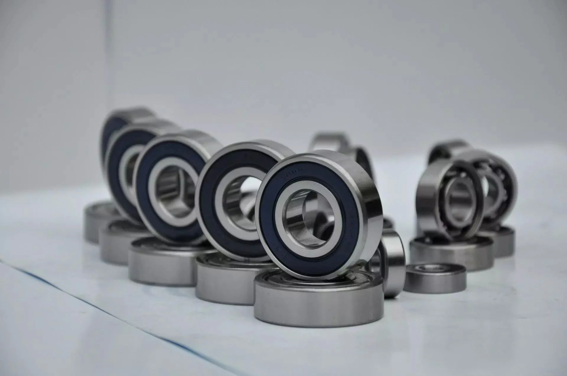
Single-row designs
Steel linear translation stages often use single-row designs for ball bearings. These types of bearings provide smooth linear travel and can withstand high loads. The material steel has a high modulus of elasticity and a high stiffness, as well as a lower thermal expansion than aluminum. For these reasons, steel is the material of choice for a ball bearing in a typical user environment. Single-row designs for ball bearings are also suitable for applications in humid or corrosive environments.
Single-row designs for ball bearings are available in a variety of sizes and are axially adjustable. They have a high radial capacity, but require relatively little space. Single-row deep groove ball bearings with snap rings are STN 02 4605 or R47, respectively. Bearings with snap rings are identified by a suffix such as NR. They may not have seals or shields installed.
These single-row angular contact ball bearings are capable of supporting axial and radial loads. In a two-raceway arrangement, the radial load on bearing A causes a radial load to act on bearing B. Both axial and radial forces are transmitted between single-row angular contact ball bearings, and the resulting internal force must be taken into account to calculate equivalent dynamic bearing loads P.
Single-row deep groove ball bearings are the most common type of ball bearings. These bearings are designed with only 1 row of rolling elements. The single-row design is simple and durable, which makes it ideal for high-speed applications. Single-row designs for ball bearings are also available in various bore sizes. They can also come in a variety of shapes and are non-separable. If you need a high-speed bearing, you may want to opt for a double-row design.
In addition to single-row designs for ball bearings, you can choose ceramic or steel ball bearings. Ceramic balls are considerably harder than steel balls, but they are not as hard as steel. Hence, ceramic bearings are stiffer than steel ball bearings, resulting in increased stress on the outer race groove and lower load capacity. This is a great benefit for those who need the bearings to be lightweight and strong.
The difference between single-row and double-row designs is in the way that the inner and outer ring are installed. A single-row design places the inner ring in an eccentric position relative to the outer ring. The 2 rings are in contact at 1 point, which causes a large gap in the bearing. The balls are then inserted through the gap. As a result, the balls are evenly distributed throughout the bearing, which forces the inner and outer rings to become concentric.
Deep-groove ball bearings are 1 of the most popular types of ball bearings. They are available in different designs, including snap-ring, seal and shield arrangements. The race diameter of a deep-groove ball bearing is close to the ball's diameter. These types of bearings are suited for heavy loads, and their axial and radial support are excellent. Their main drawback is that the contact angle cannot be adjusted to accommodate a wide range of relative loads.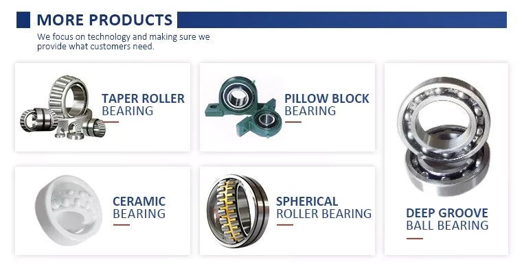
Ceramic hybrid ball bearings
Hybrid ball bearings with ceramic balls have numerous advantages. They feature improved kinematic behavior and require less lubrication. Consequently, they can reduce operating costs. Additionally, their low thermal expansion coefficient allows for smaller changes in contact angle and preload variations, and they can retain tolerances. Furthermore, ceramic hybrid ball bearings have significantly increased life spans compared to conventional steel-steel ball bearings, with up to 10 times the lifespan.
Although ceramic bearings can be used in automotive applications, many people believe that they're a poor choice for bicycle hubs. They don't reduce weight and only work well in high-rpm environments. As a result, many cyclists don't even bother with ceramic-based bearings. However, both Paul Lew and Alan are of the opinion that ceramic bearings are best suited for industrial or medical equipment applications. Furthermore, Paul and Alan believe that they are ideal for high-altitude drone motors.
Another advantage of ceramic hybrid ball bearings is that they use less friction than conventional steel-based balls. They are also more durable, requiring less lubrication than steel-based bearings. Furthermore, the lower friction and rolling resistance associated with ceramic-based ball bearings means that they can last 10 times longer than steel-based bearings. A ceramic-based hybrid ball bearing can be used for applications where speed and lubrication are critical.
Ceramic hybrid ball bearings feature both steel and silicon nitride balls. Silicon nitride balls have 50% more modulus of elasticity than steel balls and can improve accuracy and precision. Ceramic balls also have a smoother surface finish than steel balls, which reduces vibration and spindle deflection. These benefits result in increased speed and improved production quality. In addition to this, ceramic balls can also reduce the operating temperature, enhancing the work environment.
Hybrid bearings are a popular alternative to steel bearings. They have some benefits over traditional steel bearings, and are becoming a popular choice for engineered applications. Hybrid bearings are ideal for high speed machines. The material used to manufacture ceramic balls is a high-quality alloy, and is comparatively inexpensive. But you must understand that lubrication is still necessary for hybrid bearings. If you are not careful, you may end up wasting money.
These ball bearings can be used in many industries and applications, and they are widely compatible with most metals. The main advantage of hybrid ball bearings is that they are very durable. While steel balls tend to corrode and wear out, ceramic ball bearings can withstand these conditions while minimizing maintenance and replacement costs. The benefits of hybrid ball bearings are clear. So, consider switching to these newer types of ball bearings.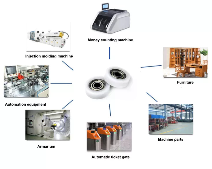
Self-aligning ball bearings
Self-aligning ball bearings are a good choice for many applications. They are a great alternative to traditional ball bearings, and they are ideal for rotating applications in which the shaft must move in several directions. They are also ideal for use in rotating parts where a tight tolerance is necessary. You can choose between 2 types: plain and flex shaft. Read on to find out which 1 will suit your needs.
Self-aligning ball bearings are designed with a higher axial load carrying capacity than single-row radial deep groove ball bearings. The amount of axial load carrying capacity is dependent upon the pressure angle. These bearings have a hollow raceway in the outer ring that allows the inner ring to pivot without friction. They are often used for high-speed applications. Because of their design, they are highly accurate.
Self-aligning ball bearings are radial bearings that feature 2 rows of balls in a spherical outer ring. They also feature 2 deep uninterrupted raceway grooves in the inner ring. Their unique features make them an excellent choice for applications where shaft deflection is a significant factor. Despite their small size, they have a high level of precision and can withstand heavy loads.
Self-aligning ball bearings can compensate for misalignment in shaft applications. The inner ring and ball assembly are positioned inside an outer ring containing a curved raceway. This spherical design allows the balls and cage to deflect and re-align around the bearing center. These bearings are also ideal for applications where shaft deflection is significant, such as in simple woodworking machinery.
Another type of self-aligning ball bearing uses a common concave outer race. Both balls and outer races automatically compensate for angular misalignment caused by machining, assembly, and deflections. Compared to spherical rollers, they have lower frictional losses than their spherical counterparts. Self-alignment ball bearings also have lower vibration levels compared to other types of bearings.
Self-aligning ball bearings operate in misaligned applications because their spherical outer raceway can accommodate misalignment. This design allows them to work in applications where shaft deflection or housing deformation is common. They are therefore more suitable for low to medium-sized loads. The only real drawback to self-aligning ball bearings is their price. If you need to purchase a self-aligning ball bearing for your next project, you can expect to pay around $1500.
China Custom China Disc Harrow Machine Tractor 3 Point Hitch Disc Harrow for Sale with Free Design Custom
Product Description
China Disc Harrow Machine Tractor 3 Point Hitch Disc Harrow for sale
PRODUCT DESCRIPTION
This 1BJ-J series Disc harrow machine 3 point hitch disc harrow for tractors is a multifunctional disc harrow. It can be 3 point mounted with tractor and also can be trailed by 4 wheel tractor. You can use this disc harrow each type according to your own different demands. This medium size disc harrow can be used as tillage machine instead of plow on the cultivated land. With the efficient productivity, reasonable utilization of the power, great ability of cutting and shattering the soil , the soil surface is smooth and loosening after harrowing, This disc harrow is well suitable for heavy clay soil, waste land and weedy field as well.
Advantages
1) It can be 3 point hitch and trailed with 4 wheel tractor.
2) The disc blade can be round or notched as your need.
3)The working depth can be adjusted freely.
PRODUCT SPECIFICATION
| Model | Unit | 1BJ-6-6 | 1BJ-7-7 | 1BJ-8-8 | 1BJ-9-9 | 1BJ-10-10 | 1BJ-11-11 | 1BJ-12-12 |
| Working width | mm | 1400 | 1600 | 1800 | 2000 | 2300 | 2500 | 2700 |
| Working depth | mm | 140 | ||||||
| Quantity of disc | pc | 12 | 14 | 16 | 18 | 20 | 22 | 24 |
| Total machine weight | kg | 440 | 490 | 550 | 590 | 620 | 650 | 720 |
| Matched power | hp | 30 | 40 | 50-60 | 60-70 | 70-80 | 80-100 | 90-110 |
| Linkage type | 3 point suspension Cat.II / Trailed | |||||||
PRODUCT SHOW
YOU MIGHT LIKE OTHER PRODUCTS
FAQ
| Q1: Are you a factory or trading company? |
| We are a factory with self-supported import and export right. |
| Q2: How can I trust on your company? |
| We are a fully registered manufacture and exporting company by China Export Registration Authorities. Moreover, our products have been exporting to a number of countries including Switzerland, Russia, Spain, Netherlands, Australia, Peru, Thailand, Pakistan, Indonesia, Tanzania, Nigeria, South Africa, Sudan, Congo etc. The good faith, punctual, strict quality control and reasonable price, throughout is the pledge we to each customer. |
| Q3: Where is your factory located? How can I visit there? |
| Our factory is located in HangZhou City, ZheJiang Province, China. About 1 hour away from HangZhou Airport. All our clients are warmly welcomed to visit us! |
| Q4: How can I place an order from your website? |
| It is very easy.Once you find the implement you need on our website and place an inquiry against it, or, get to the inquiry section and leave us a message there with name, country and phone number, we will get in touch with you at the earliest. You can also e-mail us directly or join us on live chat for instantaneous answers. |
| Q5: How can I make the payment? |
| Payment is made via Telegraphic Transfer (T/T) through the bank against the proforma invoice. 30% as prepayment and the balance when the goods are ready for shipping. Irrevocable L/C at sight could be also accepted. |
| Q6: What's the Payment terms? |
| FOB, the price of the implement without sea shipment costs. CIF, including the unit cost + marine insurance + Shipment charges to your destination port. CFR, including the unit cost + Shipment charges to your destination port. |
| Q7: At which port do you usually ship the good? |
| We usually ship goods via HangZhou, ZheJiang , HangZhou, ZheJiang port of China. |
| Q8. How about the Warranty ? |
| 12 months warranty from the time of the goods arrive at destination. |
COMPANY INFORMATION
1) Many years of manufacturing expenrience in the field of general machineries.
2) Professional engineers and test equipments to ensure the quality of each machine.
3) Factory direct selling at competitive prices.
4) Good parts assembled, strictly quality control system.5) Compact structure, beautiful appearance,small volume, light weight, fuel consumption is low, the power is great
6) Start convenient easy, low noise,little vibration,smooth operation,reliable performance.
7) OEM welcome, small order acceptable, ample supply and prompt delivery.
8) YCHS MACHIERY is a manufacturer, have own factories.
9) The biggest advantages: Top quality, Competitive price & Good after-sales service
"Top quality, Competitive price, Good after-sales service" is our big advantages.
Welcome to contact us at any time, sincerely hope we could have cooperation with you.
Have a nice day.
Screws and Screw Shafts
A screw is a mechanical device that holds objects together. Screws are usually forged or machined. They are also used in screw jacks and press-fitted vises. Their self-locking properties make them a popular choice in many different industries. Here are some of the benefits of screws and how they work. Also read about their self-locking properties. The following information will help you choose the right screw for your application.
Machined screw shaft
A machined screw shaft can be made of various materials, depending on the application. Screw shafts can be made from stainless steel, brass, bronze, titanium, or iron. Most manufacturers use high-precision CNC machines or lathes to manufacture these products. These products come in many sizes and shapes, and they have varying applications. Different materials are used for different sizes and shapes. Here are some examples of what you can use these screws for:
Screws are widely used in many applications. One of the most common uses is in holding objects together. This type of fastener is used in screw jacks, vises, and screw presses. The thread pitch of a screw can vary. Generally, a smaller pitch results in greater mechanical advantage. Hence, a machined screw shaft should be sized appropriately. This ensures that your product will last for a long time.
A machined screw shaft should be compatible with various threading systems. In general, the ASME system is used for threaded parts. The threaded hole occupies most of the shaft. The thread of the bolt occupy either part of the shaft, or the entire one. There are also alternatives to bolts, including riveting, rolling pins, and pinned shafts. These alternatives are not widely used today, but they are useful for certain niche applications.
If you are using a ball screw, you can choose to anneal the screw shaft. To anneal the screw shaft, use a water-soaked rag as a heat barrier. You can choose from 2 different options, depending on your application. One option is to cover the screw shaft with a dust-proof enclosure. Alternatively, you can install a protective heat barrier over the screw shaft. You can also choose to cover the screw shaft with a dust-proof machine.
If you need a smaller size, you can choose a smaller screw. It may be smaller than a quarter of an inch, but it may still be compatible with another part. The smaller ones, however, will often have a corresponding mating part. These parts are typically denominated by their ANSI numerical size designation, which does not indicate threads-per-inch. There is an industry standard for screw sizes that is a little easier to understand.
Ball screw nut
When choosing a Ball screw nut for a screw shaft, it is important to consider the critical speed of the machine. This value excites the natural frequency of a screw and determines how fast it can be turned. In other words, it varies with the screw diameter and unsupported length. It also depends on the screw shaft's diameter and end fixity. Depending on the application, the nut can be run at a maximum speed of about 80% of its theoretical critical speed.
The inner return of a ball nut is a cross-over deflector that forces the balls to climb over the crest of the screw. In 1 revolution of the screw, a ball will cross over the nut crest to return to the screw. Similarly, the outer circuit is a circular shape. Both flanges have 1 contact point on the ball shaft, and the nut is connected to the screw shaft by a screw.
The accuracy of ball screws depends on several factors, including the manufacturing precision of the ball grooves, the compactness of the assembly, and the set-up precision of the nut. Depending on the application, the lead accuracy of a ball screw nut may vary significantly. To improve lead accuracy, preloading, and lubrication are important. Ewellix ball screw assembly specialists can help you determine the best option for your application.
A ball screw nut should be preloaded prior to installation in order to achieve the expected service life. The smallest amount of preload required can reduce a ball screw's calculated life by as much as 90 percent. Using a lubricant of a standard grade is recommended. Some lubricants contain additives. Using grease or oil in place of oil can prolong the life of the screw.
A ball screw nut is a type of threaded nut that is used in a number of different applications. It works similar to a ball bearing in that it contains hardened steel balls that move along a series of inclined races. When choosing a ball screw nut, engineers should consider the following factors: speed, life span, mounting, and lubrication. In addition, there are other considerations, such as the environment in which the screw is used.
Self-locking property of screw shaft
A self-locking screw is 1 that is capable of rotating without the use of a lock washer or bolt. This property is dependent on a number of factors, but 1 of them is the pitch angle of the thread. A screw with a small pitch angle is less likely to self-lock, while a large pitch angle is more likely to spontaneously rotate. The limiting angle of a self-locking thread can be calculated by calculating the torque Mkdw at which the screw is first released.
The pitch angle of the screw's threads and its coefficient of friction determine the self-locking function of the screw. Other factors that affect its self-locking function include environmental conditions, high or low temperature, and vibration. Self-locking screws are often used in single-line applications and are limited by the size of their pitch. Therefore, the self-locking property of the screw shaft depends on the specific application.
The self-locking feature of a screw is an important factor. If a screw is not in a state of motion, it can be a dangerous or unusable machine. The self-locking property of a screw is critical in many applications, from corkscrews to threaded pipe joints. Screws are also used as power linkages, although their use is rarely necessary for high-power operations. In the archimedes' screw, for example, the blades of the screw rotate around an axis. A screw conveyor uses a rotating helical chamber to move materials. A micrometer uses a precision-calibrated screw to measure length.
Self-locking screws are commonly used in lead screw technology. Their pitch and coefficient of friction are important factors in determining the self-locking property of screws. This property is advantageous in many applications because it eliminates the need for a costly brake. Its self-locking property means that the screw will be secure without requiring a special kind of force or torque. There are many other factors that contribute to the self-locking property of a screw, but this is the most common factor.
Screws with right-hand threads have threads that angle up to the right. The opposite is true for left-hand screws. While turning a screw counter-clockwise will loosen it, a right-handed person will use a right-handed thumb-up to turn it. Similarly, a left-handed person will use their thumb to turn a screw counter-clockwise. And vice versa.
Materials used to manufacture screw shaft
Many materials are commonly used to manufacture screw shafts. The most common are steel, stainless steel, brass, bronze, and titanium. These materials have advantages and disadvantages that make them good candidates for screw production. Some screw types are also made of copper to fight corrosion and ensure durability over time. Other materials include nylon, Teflon, and aluminum. Brass screws are lightweight and have aesthetic appeal. The choice of material for a screw shaft depends on the use it will be made for.
Shafts are typically produced using 3 steps. Screws are manufactured from large coils, wire, or round bar stock. After these are produced, the blanks are cut to the appropriate length and cold headed. This cold working process pressudes features into the screw head. More complicated screw shapes may require 2 heading processes to achieve the desired shape. The process is very precise and accurate, so it is an ideal choice for screw manufacturing.
The type of material used to manufacture a screw shaft is crucial for the function it will serve. The type of material chosen will depend on where the screw is being used. If the screw is for an indoor project, you can opt for a cheaper, low-tech screw. But if the screw is for an outdoor project, you'll need to use a specific type of screw. This is because outdoor screws will be exposed to humidity and temperature changes. Some screws may even be coated with a protective coating to protect them from the elements.
Screws can also be self-threading and self-tapping. The self-threading or self-tapping screw creates a complementary helix within the material. Other screws are made with a thread which cuts into the material it fastens. Other types of screws create a helical groove on softer material to provide compression. The most common uses of a screw include holding 2 components together.
There are many types of bolts available. Some are more expensive than others, but they are generally more resistant to corrosion. They can also be made from stainless steel or aluminum. But they require high-strength materials. If you're wondering what screws are, consider this article. There are tons of options available for screw shaft manufacturing. You'll be surprised how versatile they can be! The choice is yours, and you can be confident that you'll find the screw shaft that will best fit your application.