Product Description
| Size | 260 cm * 120 cm * 135 cm |
| Drive Wheel | 4WD |
| Power | 12(Kw) |
| Specification | 30-50HP |
| Fuel | Gas / Diesel |
| Weight | 680(kg) |
| Tyres sizes | 500-12/650-16 |
| Usage | Farm Tractor, Garden Tractor, Lawn Tractor |
This is part of the certificate, please contact us if you need more!
We can provide customers with customizable packaging, a large number of goods in stock, and a wide choice of freight routes.
Q1: Can I have a sample order?
A1: Yes, we accept sample order to test and check quality.
Q2: Do you have MOQ limit?
A2: Yes, we have MOQ limit for mass production, but it depends on model. Please contact us for details.
Q3: How about the lead time?
A3: Samples will takes 5-7 business days. Mass production will takes 25-30 days. It depends on quantity.
Q4: How about shipping and delivery time?
A4: Generally, Item will be shipped via Express, such as DHL, TNT, FedEx and UPS, delivery time is 3-7 business days. Airline and sea shipping also available.
In order to better serve customers, we now make the following disclaimer for the product information published on the website that contains text, pictures, and links:
1. The product picture may have a color difference with the actual product due to the different angle and light, as well as the display difference of the monitor. The picture is for reference only, the actual product shall prevail, please contact our staff for more details.
2. It is the customized product, not final retail product. Details, description, pictures, and specifications are subject to the final confirmed order.
3. The price is for reference only, the market price is fluctuating, and the price marked on this page is not the only basis for the final transaction. Please contact our sales staff to confirm the final price.
|
Shipping Cost:
Estimated freight per unit. |
To be negotiated |
|---|
| After-sales Service: | 6 Months |
|---|---|
| Warranty: | 6 Months |
| Type: | Wheel Tractor |
| Samples: |
US$ 16999/Piece
1 Piece(Min.Order) | Order Sample |
|---|
| Customization: |
Available
| Customized Request |
|---|

How do manufacturers ensure the compatibility of PTO shafts with different equipment?
Manufacturers employ various measures to ensure the compatibility of PTO (Power Take-Off) shafts with different equipment. Compatibility is crucial to ensure that PTO shafts can effectively transfer power from the power source to the driven machinery without compromising performance, safety, or ease of use. Here's a detailed explanation of how manufacturers ensure compatibility:
1. Standardization: PTO shafts are designed and manufactured based on standardized specifications. These specifications outline the essential parameters such as shaft dimensions, spline sizes, torque ratings, and safety requirements. By adhering to standardized designs, manufacturers ensure that PTO shafts are compatible with a wide range of equipment that meets the same standards. Standardization allows for interchangeability, meaning that PTO shafts from one manufacturer can be used with equipment from another manufacturer as long as they conform to the same specifications.
2. Collaboration with Equipment Manufacturers: PTO shaft manufacturers often collaborate closely with equipment manufacturers to ensure compatibility. They work together to understand the specific requirements of the equipment and design PTO shafts that seamlessly integrate with the machinery. This collaboration may involve sharing technical specifications, conducting joint testing, and exchanging feedback. By working in partnership, manufacturers can address any compatibility issues early in the design and development process, resulting in PTO shafts that are tailored to the equipment's needs.
3. Customization Options: PTO shaft manufacturers offer customization options to accommodate different equipment configurations. They provide flexibility in terms of shaft length, spline sizes, yoke designs, and coupling mechanisms. Equipment manufacturers can specify the required parameters, and the PTO shafts can be customized accordingly. This ensures that the PTO shafts precisely match the equipment's power input/output requirements and connection methods, guaranteeing compatibility and efficient power transfer.
4. Testing and Validation: Manufacturers conduct rigorous testing and validation processes to ensure the compatibility and performance of PTO shafts. They subject the shafts to various tests, including torque testing, rotational speed testing, and durability testing. These tests verify that the PTO shafts can handle the expected power loads and operating conditions without failure. By validating the performance of the PTO shafts, manufacturers can ensure that they are compatible with a wide range of equipment and can reliably transfer power under different operating scenarios.
5. Compliance with Industry Standards: PTO shaft manufacturers adhere to industry standards and regulations to ensure compatibility. Organizations such as the American Society of Agricultural and Biological Engineers (ASABE) establish safety and performance standards for PTO shafts. Manufacturers design and produce their shafts in accordance with these standards, ensuring that their products meet the necessary requirements for compatibility and safety. Compliance with industry standards provides assurance to equipment manufacturers and end-users that the PTO shafts are compatible and suitable for use with different equipment.
6. Documentation and Guidelines: Manufacturers provide comprehensive documentation and guidelines to assist equipment manufacturers and end-users in ensuring compatibility. This documentation includes technical specifications, installation instructions, maintenance guidelines, and safety recommendations. The documentation helps equipment manufacturers select the appropriate PTO shaft for their equipment and provides guidance on proper installation and use. By following the manufacturer's guidelines, equipment manufacturers can ensure compatibility and optimize the performance of the PTO shafts.
7. Ongoing Research and Development: PTO shaft manufacturers continuously invest in research and development to enhance compatibility with different equipment. They stay updated with industry trends, technological advancements, and evolving equipment requirements. This ongoing research and development enable manufacturers to improve the design, materials, and features of PTO shafts, ensuring compatibility with the latest equipment innovations and addressing any compatibility challenges that may arise.
By employing standardization, collaborating with equipment manufacturers, offering customization options, conducting thorough testing, complying with industry standards, providing documentation and guidelines, and investing in research and development, manufacturers ensure the compatibility of PTO shafts with different equipment. This compatibility allows for seamless integration, efficient power transfer, and optimal performance across a wide range of machinery and equipment in various industries.

Can PTO shafts be customized for specific machinery and power requirements?
Yes, PTO (Power Take-Off) shafts can be customized to meet the specific machinery and power requirements of different applications. Manufacturers offer customization options to ensure that PTO shafts are precisely tailored to the power source, driven machinery, and the intended application. Here's a detailed explanation of how PTO shafts can be customized:
1. Shaft Length: PTO shafts can be customized in terms of length to accommodate different equipment configurations. The length of the PTO shaft is critical to ensure proper alignment and connection between the power source and driven machinery. Manufacturers can provide PTO shafts with adjustable or fixed-length options, allowing for flexibility in meeting specific length requirements. Customizing the shaft length ensures that the PTO shaft fits the equipment properly, optimizing power transfer efficiency and reducing the risk of misalignment or excessive stress.
2. Spline Sizes: PTO shafts are available with different spline sizes to match the input and output shafts of various equipment. Spline size customization allows the PTO shaft to seamlessly connect to the power source and driven machinery. Manufacturers can offer different spline configurations, such as 1-3/8 inch, 1-3/4 inch, or metric sizes, to accommodate specific machinery requirements. Customizing the spline size ensures a proper fit and secure connection, enabling efficient power transfer without the need for additional adapters or modifications.
3. Yoke Designs: PTO shafts can be customized with different yoke designs to match the connection points on the power source and driven machinery. The yoke is the component that attaches to the shaft and connects to the equipment. Manufacturers can provide various yoke designs, such as round, triangular, or splined yokes, to ensure compatibility with specific machinery. Customizing the yoke design allows for a secure and reliable connection, aligning the PTO shaft with the equipment's input/output shafts and optimizing power transmission efficiency.
4. Torque Ratings: PTO shafts can be customized to handle specific torque requirements based on the power demands of the application. Torque is the rotational force that the PTO shaft needs to transmit from the power source to the driven machinery. Manufacturers can design PTO shafts with different torque ratings by using appropriate materials, dimensions, and reinforcement techniques. Customizing the torque rating ensures that the PTO shaft can safely and reliably handle the required power levels without premature wear or failure.
5. Coupling Mechanisms: PTO shafts can be customized with different coupling mechanisms to match the connection requirements of specific equipment. Coupling mechanisms are the means by which the PTO shaft connects and disconnects from the power source and driven machinery. Manufacturers can provide various coupling options, such as quick-release couplings, shear pin couplings, or mechanical lock couplings, to accommodate different machinery designs and operational needs. Customizing the coupling mechanism ensures ease of use, secure attachment, and quick disengagement when necessary.
6. Protective Features: PTO shafts can be customized with additional protective features to enhance safety and durability. These features may include guard shields, safety covers, or slip clutches. Guard shields and safety covers provide physical protection by enclosing the rotating shaft and preventing accidental contact, reducing the risk of injuries. Slip clutches offer overload protection by allowing the PTO shaft to slip or disengage when excessive torque or resistance is encountered, preventing damage to the shaft and associated equipment. Customizing the protective features ensures compliance with safety regulations and addresses specific safety requirements of the machinery or application.
7. Material Selection: PTO shafts can be customized with different materials based on the application's demands. Manufacturers can offer a range of material options, such as steel, aluminum, or composite materials, with varying strength, weight, and corrosion resistance properties. Customizing the material selection allows for optimizing the PTO shaft's performance, considering factors like operating conditions, environmental exposure, and weight restrictions.
By providing customization options such as shaft length, spline sizes, yoke designs, torque ratings, coupling mechanisms, protective features, and material selection, manufacturers can ensure that PTO shafts are specifically tailored to meet the machinery and power requirements of different applications. Customized PTO shafts facilitate seamless integration, efficient power transfer, and reliable operation, enhancing the overall performance and productivity of the equipment.

Can you explain the different types of PTO shafts and their applications?
PTO shafts (Power Take-Off shafts) come in various types, each designed for specific applications and requirements. The different types of PTO shafts offer versatility and compatibility with a wide range of machinery and implements. Here's an explanation of the most common types of PTO shafts and their applications:
1. Standard PTO Shaft: The standard PTO shaft, also known as a splined shaft, is the most common type used in agricultural and industrial machinery. It consists of a solid steel shaft with splines or grooves along its length. The standard PTO shaft typically has six splines, although variations with four or eight splines can be found. This type of PTO shaft is widely used in tractors and various implements, including mowers, balers, tillers, and rotary cutters. The splines provide a secure connection between the power source and the driven machinery, ensuring efficient power transfer.
2. Shear Bolt PTO Shaft: Shear bolt PTO shafts are designed with a safety feature that allows the shaft to separate in case of overload or sudden shock to protect the driveline components. These PTO shafts incorporate a shear bolt mechanism that connects the tractor's power take-off to the driven machinery. In the event of excessive load or sudden resistance, the shear bolt is designed to break, disconnecting the PTO shaft and preventing damage to the driveline. Shear bolt PTO shafts are commonly used in equipment that may encounter sudden obstructions or high-stress situations, such as wood chippers, stump grinders, and heavy-duty rotary cutters.
3. Friction Clutch PTO Shaft: Friction clutch PTO shafts feature a clutch mechanism that allows for smooth engagement and disengagement of the power transfer. These PTO shafts typically incorporate a friction disc and a pressure plate, similar to a traditional vehicle clutch system. The friction clutch allows operators to gradually engage or disengage the power transfer, reducing shock loads and minimizing wear on the driveline components. Friction clutch PTO shafts are commonly used in applications where precise control of power engagement is required, such as in hydraulic pumps, generators, and industrial mixers.
4. Constant Velocity (CV) PTO Shaft: Constant Velocity (CV) PTO shafts, also known as homokinetic shafts, are designed to accommodate high angles of misalignment without affecting power transmission. They use a universal joint mechanism that allows for smooth power transfer even when the driven machinery is at an angle relative to the power source. CV PTO shafts are frequently used in applications where the machinery requires a significant range of movement or articulation, such as in articulated loaders, telescopic handlers, and self-propelled sprayers.
5. Telescopic PTO Shaft: Telescopic PTO shafts are adjustable in length, allowing for flexibility in equipment configuration and varying distances between the power source and the driven machinery. They consist of two or more concentric shafts that slide within each other, providing the ability to extend or retract the PTO shaft as needed. Telescopic PTO shafts are commonly used in applications where the distance between the tractor's power take-off and the implement varies, such as in front-mounted implements, snow blowers, and self-loading wagons. The telescopic design enables easy adaptation to different equipment setups and minimizes the risk of the PTO shaft dragging on the ground.
6. Gearbox PTO Shaft: Gearbox PTO shafts are designed to adapt power transmission between different rotational speeds or directions. They incorporate a gearbox mechanism that allows for speed reduction or increase, as well as the ability to change rotational direction. Gearbox PTO shafts are commonly used in applications where the driven machinery requires a different speed or rotational direction than the tractor's power take-off. Examples include grain augers, feed mixers, and industrial equipment that requires specific speed ratios or reversing capabilities.
It's important to note that the availability and specific applications of PTO shaft types may vary based on regional and industry-specific factors. Additionally, certain machinery or implements may require specialized or custom PTO shafts to meet specific requirements.
In summary, the different types of PTO shafts, such as standard, shear bolt, friction clutch, constant velocity (CV), telescopic, and gearbox shafts, offer versatility and compatibility with various machinery and implements. Each type of PTO shaft is designed to address specific needs, such as power transfer efficiency, safety, smooth engagement, misalignment tolerance, adaptability, and speed/direction adjustment. Understanding the different types of PTO shafts and their applications is crucial for selecting the appropriate shaft forthe intended machinery and ensuring optimal performance and reliability.

editor by CX 2023-09-14
China Standard Spain Hot Selling Garden Tractor Backhoe Lw-7e 30-55HP Tractor Mounted 16 Inch Width Bucket Hydraulic Sideshift Backhoe with ISO Ce Co Certificate near me factory
Product Description
Spain hot selling Garden Tractor Backhoe LW-7E 30-55HP Tractor mounted 16 inch width bucket Hydraulic Sideshift Backhoe with ISO CE CO certificate
LW-7E Backhoe Main Features, drawing show and Specification:
Perfect working performance of our Backhoe:
High quality Backhoe have ISO,CE, PVOC COC, CO etc certificates:
Backhoe Personalized Packing and Transporting Service to meet different customers' demand :
Top-rank technical team and Advance R&D Center :
Advance Production workshop :
Strictly inspect for every set machine before Goods Delivery :
Perfect after-sale service for both Distributors and Private customers:
Please contact us if you have any demand for our Product :
Best price will be quoted for you as soon as receive your Requirement !
How to Identify a Faulty Drive Shaft
The most common problems associated with automotive driveshafts include clicking and rubbing noises. While driving, the noise from the driver's seat is often noticeable. An experienced auto mechanic can easily identify whether the sound is coming from both sides or from 1 side. If you notice any of these signs, it's time to send your car in for a proper diagnosis. Here's a guide to determining if your car's driveshaft is faulty:
Symptoms of Driveshaft Failure
If you're having trouble turning your car, it's time to check your vehicle's driveshaft. A bad driveshaft can limit the overall control of your car, and you should fix it as soon as possible to avoid further problems. Other symptoms of a propshaft failure include strange noises from under the vehicle and difficulty shifting gears. Squeaking from under the vehicle is another sign of a faulty driveshaft.
If your driveshaft fails, your car will stop. Although the engine will still run, the wheels will not turn. You may hear strange noises from under the vehicle, but this is a rare symptom of a propshaft failure. However, you will have plenty of time to fix the problem. If you don't hear any noise, the problem is not affecting your vehicle's ability to move.
The most obvious signs of a driveshaft failure are dull sounds, squeaks or vibrations. If the drive shaft is unbalanced, it is likely to damage the transmission. It will require a trailer to remove it from your vehicle. Apart from that, it can also affect your car's performance and require repairs. So if you hear these signs in your car, be sure to have it checked by a mechanic right away.
Drive shaft assembly
When designing a propshaft, the design should be based on the torque required to drive the vehicle. When this torque is too high, it can cause irreversible failure of the drive shaft. Therefore, a good drive shaft design should have a long service life. Here are some tips to help you design a good driveshaft. Some of the main components of the driveshaft are listed below.
Snap Ring: The snap ring is a removable part that secures the bearing cup assembly in the yoke cross hole. It also has a groove for locating the snap ring. Spline: A spline is a patented tubular machined element with a series of ridges that fit into the grooves of the mating piece. The bearing cup assembly consists of a shaft and end fittings.
U-joint: U-joint is required due to the angular displacement between the T-shaped housing and the pinion. This angle is especially large in raised 4x4s. The design of the U-joint must guarantee a constant rotational speed. Proper driveshaft design must account for the difference in angular velocity between the shafts. The T-bracket and output shaft are attached to the bearing caps at both ends.
U-joint
Your vehicle has a set of U-joints on the driveshaft. If your vehicle needs to be replaced, you can do it yourself. You will need a hammer, ratchet and socket. In order to remove the U-joint, you must first remove the bearing cup. In some cases you will need to use a hammer to remove the bearing cup, you should be careful as you don't want to damage the drive shaft. If you cannot remove the bearing cup, you can also use a vise to press it out.
There are 2 types of U-joints. One is held by a yoke and the other is held by a c-clamp. A full ring is safer and ideal for vehicles that are often used off-road. In some cases, a full circle can be used to repair a c-clamp u-joint.
In addition to excessive torque, extreme loads and improper lubrication are common causes of U-joint failure. The U-joint on the driveshaft can also be damaged if the engine is modified. If you are driving a vehicle with a heavily modified engine, it is not enough to replace the OE U-joint. In this case, it is important to take the time to properly lubricate these components as needed to keep them functional.
tube yoke
QU40866 Tube Yoke is a common replacement for damaged or damaged driveshaft tubes. They are desirably made of a metallic material, such as an aluminum alloy, and include a hollow portion with a lug structure at 1 end. Tube yokes can be manufactured using a variety of methods, including casting and forging. A common method involves drawing solid elements and machining them into the final shape. The resulting components are less expensive to produce, especially when compared to other forms.
The tube fork has a connection point to the driveshaft tube. The lug structure provides attachment points for the gimbal. Typically, the driveshaft tube is 5 inches in diameter and the lug structure is 4 inches in diameter. The lug structure also serves as a mounting point for the drive shaft. Once installed, Tube Yoke is easy to maintain. There are 2 types of lug structures: 1 is forged tube yoke and the other is welded.
Heavy-duty series drive shafts use bearing plates to secure the yoke to the U-joint. All other dimensions are secured with external snap rings. Yokes are usually machined to accept U-bolts. For some applications, grease fittings are used. This attachment is more suitable for off-road vehicles and performance vehicles.
end yoke
The end yoke of the drive shaft is an integral part of the drive train. Choosing a high-quality end yoke will help ensure long-term operation and prevent premature failure. Pat's Driveline offers a complete line of automotive end yokes for power take-offs, differentials and auxiliary equipment. They can also measure your existing parts and provide you with high quality replacements.
A U-bolt is an industrial fastener with threaded legs. When used on a driveshaft, it provides greater stability in unstable terrain. You can purchase a U-bolt kit to secure the pinion carrier to the drive shaft. U-bolts also come with lock washers and nuts. Performance cars and off-road vehicles often use this type of attachment. But before you install it, you have to make sure the yoke is machined to accept it.
End yokes can be made of aluminum or steel and are designed to provide strength. It also offers special bolt styles for various applications. CZPT's drivetrain is also stocked with a full line of automotive flange yokes. The company also produces custom flanged yokes for many popular brands. Since the company has a comprehensive line of replacement flange yokes, it can help you transform your drivetrain from non-serviceable to serviceable.
bushing
The first step in repairing or replacing an automotive driveshaft is to replace worn or damaged bushings. These bushings are located inside the drive shaft to provide a smooth, safe ride. The shaft rotates in a rubber sleeve. If a bushing needs to be replaced, you should first check the manual for recommendations. Some of these components may also need to be replaced, such as the clutch or swingarm.


China factory Ce Approved High Quality Tractor Attachment Lwe Series Towable Pto Shaft Drive Side Shift Hydraulic Mini Garden Backhoe for 20-120HP Tractor with Free Design Custom
Product Description
CE Approved High quality Tractor attachment LWE series Towable PTO drive Side shift Hydraulic mini garden Backhoe for 20-120HP tractor
LWE Sideshit Backhoe Main Features, drawing show and Specification:
Perfect working performance of our Backhoe:
High quality Backhoe have ISO,CE, PVOC COC, CO etc certificates:
Backhoe Personalized Packing and Transporting Service to meet different customers' demand :
Top-rank technical team and Advance R&D Center :
Advance Production workshop :
Strictly inspect for every set machine before Goods Delivery :
Perfect after-sale service for both Distributors and Private customers:
Please contact us if you have any demand for our Product :
Best price will be quoted for you as soon as receive your Requirement !
How to Compare Different Types of Spur Gears
When comparing different types of spur gears, there are several important considerations to take into account. The main considerations include the following: Common applications, Pitch diameter, and Addendum circle. Here we will look at each of these factors in more detail. This article will help you understand what each type of spur gear can do for you. Whether you're looking to power an electric motor or a construction machine, the right gear for the job will make the job easier and save you money in the long run.
Common applications
Among its many applications, a spur gear is widely used in airplanes, trains, and bicycles. It is also used in ball mills and crushers. Its high speed-low torque capabilities make it ideal for a variety of applications, including industrial machines. The following are some of the common uses for spur gears. Listed below are some of the most common types. While spur gears are generally quiet, they do have their limitations.
A spur gear transmission can be external or auxiliary. These units are supported by front and rear casings. They transmit drive to the accessory units, which in turn move the machine. The drive speed is typically between 5000 and 6000 rpm or 20,000 rpm for centrifugal breathers. For this reason, spur gears are typically used in large machinery. To learn more about spur gears, watch the following video.
The pitch diameter and diametral pitch of spur gears are important parameters. A diametral pitch, or ratio of teeth to pitch diameter, is important in determining the center distance between 2 spur gears. The center distance between 2 spur gears is calculated by adding the radius of each pitch circle. The addendum, or tooth profile, is the height by which a tooth projects above the pitch circle. Besides pitch, the center distance between 2 spur gears is measured in terms of the distance between their centers.
Another important feature of a spur gear is its low speed capability. It can produce great power even at low speeds. However, if noise control is not a priority, a helical gear is preferable. Helical gears, on the other hand, have teeth arranged in the opposite direction of the axis, making them quieter. However, when considering the noise level, a helical gear will work better in low-speed situations.
Construction
The construction of spur gear begins with the cutting of the gear blank. The gear blank is made of a pie-shaped billet and can vary in size, shape, and weight. The cutting process requires the use of dies to create the correct gear geometry. The gear blank is then fed slowly into the screw machine until it has the desired shape and size. A steel gear blank, called a spur gear billet, is used in the manufacturing process.
A spur gear consists of 2 parts: a centre bore and a pilot hole. The addendum is the circle that runs along the outermost points of a spur gear's teeth. The root diameter is the diameter at the base of the tooth space. The plane tangent to the pitch surface is called the pressure angle. The total diameter of a spur gear is equal to the addendum plus the dedendum.
The pitch circle is a circle formed by a series of teeth and a diametrical division of each tooth. The pitch circle defines the distance between 2 meshed gears. The center distance is the distance between the gears. The pitch circle diameter is a crucial factor in determining center distances between 2 mating spur gears. The center distance is calculated by adding the radius of each gear's pitch circle. The dedendum is the height of a tooth above the pitch circle.
Other considerations in the design process include the material used for construction, surface treatments, and number of teeth. In some cases, a standard off-the-shelf gear is the most appropriate choice. It will meet your application needs and be a cheaper alternative. The gear will not last for long if it is not lubricated properly. There are a number of different ways to lubricate a spur gear, including hydrodynamic journal bearings and self-contained gears.
Addendum circle
The pitch diameter and addendum circle are 2 important dimensions of a spur gear. These diameters are the overall diameter of the gear and the pitch circle is the circle centered around the root of the gear's tooth spaces. The addendum factor is a function of the pitch circle and the addendum value, which is the radial distance between the top of the gear tooth and the pitch circle of the mating gear.
The pitch surface is the right-hand side of the pitch circle, while the root circle defines the space between the 2 gear tooth sides. The dedendum is the distance between the top of the gear tooth and the pitch circle, and the pitch diameter and addendum circle are the 2 radial distances between these 2 circles. The difference between the pitch surface and the addendum circle is known as the clearance.
The number of teeth in the spur gear must not be less than 16 when the pressure angle is 20 degrees. However, a gear with 16 teeth can still be used if its strength and contact ratio are within design limits. In addition, undercutting can be prevented by profile shifting and addendum modification. However, it is also possible to reduce the addendum length through the use of a positive correction. However, it is important to note that undercutting can happen in spur gears with a negative addendum circle.
Another important aspect of a spur gear is its meshing. Because of this, a standard spur gear will have a meshing reference circle called a Pitch Circle. The center distance, on the other hand, is the distance between the center shafts of the 2 gears. It is important to understand the basic terminology involved with the gear system before beginning a calculation. Despite this, it is essential to remember that it is possible to make a spur gear mesh using the same reference circle.
Pitch diameter
To determine the pitch diameter of a spur gear, the type of drive, the type of driver, and the type of driven machine should be specified. The proposed diametral pitch value is also defined. The smaller the pitch diameter, the less contact stress on the pinion and the longer the service life. Spur gears are made using simpler processes than other types of gears. The pitch diameter of a spur gear is important because it determines its pressure angle, the working depth, and the whole depth.
The ratio of the pitch diameter and the number of teeth is called the DIAMETRAL PITCH. The teeth are measured in the axial plane. The FILLET RADIUS is the curve that forms at the base of the gear tooth. The FULL DEPTH TEETH are the ones with the working depth equal to 2.000 divided by the normal diametral pitch. The hub diameter is the outside diameter of the hub. The hub projection is the distance the hub extends beyond the gear face.
A metric spur gear is typically specified with a Diametral Pitch. This is the number of teeth per inch of the pitch circle diameter. It is generally measured in inverse inches. The normal plane intersects the tooth surface at the point where the pitch is specified. In a helical gear, this line is perpendicular to the pitch cylinder. In addition, the pitch cylinder is normally normal to the helix on the outside.
The pitch diameter of a spur gear is typically specified in millimeters or inches. A keyway is a machined groove on the shaft that fits the key into the shaft's keyway. In the normal plane, the pitch is specified in inches. Involute pitch, or diametral pitch, is the ratio of teeth per inch of diameter. While this may seem complicated, it's an important measurement to understand the pitch of a spur gear.
Material
The main advantage of a spur gear is its ability to reduce the bending stress at the tooth no matter the load. A typical spur gear has a face width of 20 mm and will fail when subjected to 3000 N. This is far more than the yield strength of the material. Here is a look at the material properties of a spur gear. Its strength depends on its material properties. To find out what spur gear material best suits your machine, follow the following steps.
The most common material used for spur gears is steel. There are different kinds of steel, including ductile iron and stainless steel. S45C steel is the most common steel and has a 0.45% carbon content. This type of steel is easily obtainable and is used for the production of helical, spur, and worm gears. Its corrosion resistance makes it a popular material for spur gears. Here are some advantages and disadvantages of steel.
A spur gear is made of metal, plastic, or a combination of these materials. The main advantage of metal spur gears is their strength to weight ratio. It is about 1 third lighter than steel and resists corrosion. While aluminum is more expensive than steel and stainless steel, it is also easier to machine. Its design makes it easy to customize for the application. Its versatility allows it to be used in virtually every application. So, if you have a specific need, you can easily find a spur gear that fits your needs.
The design of a spur gear greatly influences its performance. Therefore, it is vital to choose the right material and measure the exact dimensions. Apart from being important for performance, dimensional measurements are also important for quality and reliability. Hence, it is essential for professionals in the industry to be familiar with the terms used to describe the materials and parts of a gear. In addition to these, it is essential to have a good understanding of the material and the dimensional measurements of a gear to ensure that production and purchase orders are accurate.
China wholesaler Anon Agricultural Wheel Farm Garden Front End Loader in Tractor near me shop
Product Description
ANON Agricultural Wheel Farm Garden Front End Loader in tractor
1.It is used for ditching in farms and grazing lands,digging pool,cleaning waterways as well as assistant excavating work in construction and building roads.
2.Hydraulic transmission is used,Featured with compact structure, flexibility, convenient operation and quick mounting and dismounting.
3.It uses hydraulic oil commonly with tractor. The hydraulic elements are standardized, convenient for operation and service.
Specification of 4*4 wheel 40hp tractor with front end loader and backhoe
| Model | LW-6 | LW-7 | LW-8 | LW-9 |
| Tractor HP | 25-30HP | 30-45HP | 45-60HP | 60-80HP |
| 3-Point Linkage | Cat-1 | Cat-1&2 | ||
| Structure Weight | 480kgs | 500kgs | 580kgs | 620kgs |
| Digging Depth(Two foot flat bottom) | 1750mm | 1950mm | 2250mm | 2550mm |
| Reach from center line of Swing Pivot | 2600mm | 2900mm | 3200mm | 3600mm |
| Loading Height(bucket at 60 degree) | 1720mm | 1840mm | 1930mm | 2210mm |
| Transport Height(MAX) | 1840mm | 2060mm | 2130mm | 2480mm |
| Extend Height | 2870mm | 3110mm | 3240mm | 3590mm |
| Loading Reach(bucket at 60degree) | 950mm | 1180mm | 1140mm | 1360mm |
| Transport Overhang | 1080mm | 1110mm | 1220mm | 1270mm |
| Undercut | 730mm | 830mm | 470mm | 520mm |
| Bucket Rotation | 180degree | |||
| Stabilizer Spread(up position) | 1310mm | 1310mm | 1310mm | 1310mm |
| Stabilizer Spread(down position) | 2100mm | 2100mm | 2340mm | 2340mm |
| Swing Arc | 180 degree | |||
| Bucket Width | 300mm | 400mm | 450mm | 500mm |
| Bucket Cubage | 0.036 | 0.045 | 0.052 | 0.063 |
Calculate the ideal mechanical advantage of pulleys
The basic equations for pulleys can be found in this article. It will also cover the different types of pulleys, the ideal mechanical advantages of pulleys, and some common uses of pulley systems. Read on to learn more! After all, a pulley is a simple mechanical device that changes the direction of a force. Learn more about pulleys and their common uses in engineering.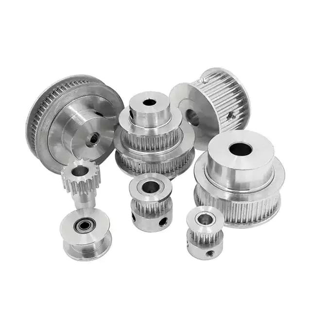
pulley basic equation
Pulleys work the same way as gravity, so they should withstand similar forces. Newton's laws of motion can be used to calculate the forces in a pulley system. The second law of motion applies to forces and accelerations. Similar to this is Newton's third law, which states that the directions of forces are equal and opposite. The fourth law dictates the direction of force. The Fifth Law states that tension is in equilibrium with gravity.
A pulley is a simple mechanism that transmits force by changing direction. They are generally considered to have negligible mass and friction, but this is only an approximation. Pulleys have different uses, from sailboats to farms and large construction cranes. In fact, they are the most versatile mechanisms in any system. Some of their most common applications and equations are listed below.
For example, consider 2 masses m. Those of mass m will be connected by pulleys. The static friction coefficient of the left stop is ms1, and the static friction coefficient of the right stop is ms2. A no-slip equation will contain multiple inequalities. If the 2 blocks are considered to be connected by a pulley, the coefficient of kinetic friction is mk. In other words, the weight of each block carries the same mass, but in the opposite direction.
Types of pulleys
A pulley is a device used to pull and push objects. Pulley systems are ropes, cables, belts or chains. The "drive pulley" is attached to the shaft and moves the driven pulley. They are available in a variety of sizes, and the larger they are, the higher the speed of power transmission. Alternatively, use small pulleys for smaller applications.
Two-wheel pulleys have 2 mechanical advantages. The greater the mechanical advantage, the less force is required to move the object. More wheels lift more weight, but smaller pulleys require less force. In a two-wheel pulley system, the rope is wound around 2 axles and a fixed surface. As you pull on the rope, the shafts above slowly come together.
Compound pulleys have 2 or more rope segments that are pulled up on the load. The mechanical advantage of compound pulleys depends on the number of rope segments and how they are arranged. This type of pulley can increase the force by changing the direction of the rope segment. There are 2 main types of pulleys. Composite pulleys are most commonly used in construction. The ideal mechanical advantage of pulleys is 2 or more.
Construction pulleys are a basic type. They are usually attached to wheel rails and can be lifted to great heights. Combinations of axes are also common. Construction pulleys can be raised to great heights to access materials or equipment. When used in construction, these pulleys are usually made of heavy materials such as wood or metal. They are secured with ropes or chains.
The ideal mechanical advantage of pulleys
The pulley system is a highly complex system with high mechanical advantages. Use a single pulley system to reduce the force required to lift an object by cutting it in half. The mechanical advantage increases as you add more pulleys, such as 6 or seven. To calculate the mechanical advantage of a pulley system, you need to count the number of rope segments between the pulleys. If the free end of the rope is facing down, don't count it. If it's facing up, count. Once you have your number, add it up.
The required mechanical advantage of a pulley is the number of rope segments it has to pull the load. The more rope segments, the lower the force. Therefore, the more rope segments the pulley has, the lower the force. If the rope segments are four, then the ideal mechanical advantage is four. In this case, the composite pulley quadrupled the load force.
The ideal mechanical advantage of a pulley system is the sum of the mechanical force and the force required to lift the load at its output. Typically, a single pulley system uses 2 ropes, and the mechanical force required to lift the load is multiplied by the 2 ropes. For a multi-pulley system, the number of ropes will vary, but the total energy requirement will remain the same. The friction between the rope and pulley increases the force and energy required to lift the load, so the mechanical advantage diminishes over time.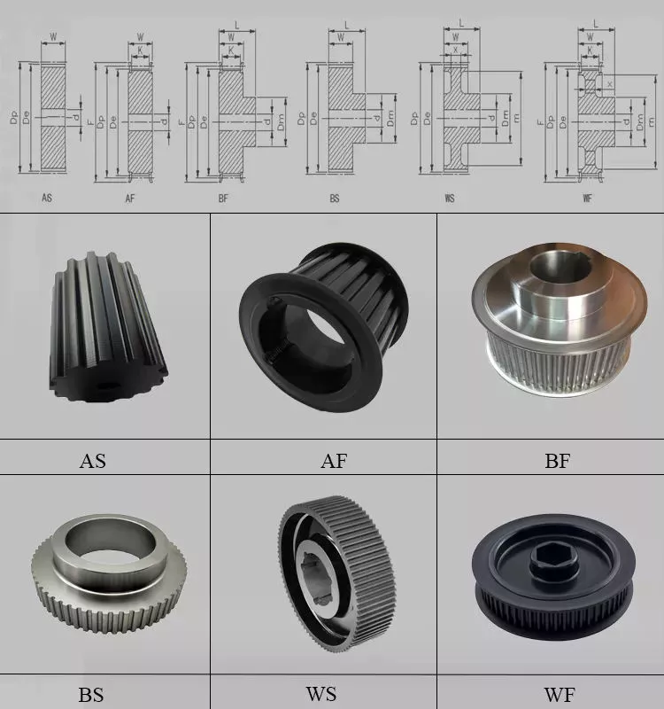
Common uses of pulley systems
A pulley system is a simple mechanical device typically used to lift heavy objects. It consists of a rotating wheel attached to a fixed shaft and a rope attached to it. When the wheel moves, the force applied by the operator is multiplied by the speed of the pulley, and the force is multiplied by the weight of the object being lifted. Common uses for pulley systems include pulling, lifting, and moving heavy objects.
The oil and petroleum industries use pulley systems in a variety of applications. Most commonly, pulleys are used in drilling operations and they are installed on top of the rig to guide the cable. The cable itself is attached to 2 pulleys suspended in the derrick, where they provide mechanical energy to the cable. Using a pulley system in this application provides the force needed to move the cable safely and smoothly.
The main advantage of the pulley system is that it minimizes the force required to lift an object. The force used to lift the object is multiplied by the desired mechanical advantage. The more rope segments, the lower the force required. On the other hand, a compound pulley system can have many segments. Therefore, a compound pulley system can increase the force a worker can exert on an object.
Safety Precautions to Take When Working on Pulley Systems
There are many safety precautions that should be observed when working on a pulley system. The first is to wear proper protective gear. This includes hard hats that protect you from falling objects. Also, gloves may be required. You should limit the amount of movement in the penalty area, and you should also keep the area free of unnecessary people and objects. Also, remember to wear a hard hat when working on the pulley system.
Another important safety precaution when working on a pulley system is to check the Safe Working Load (SWL) of the pulley before attaching anything. This will help you understand the maximum weight the pulley can hold. Also, consider the angle and height of the pulley system. Always use safety anchors and always remember to wear a hat when working on a pulley system.
Safe use of chain hoists requires training and experience. It is important to read the manufacturer's manual and follow all safety precautions. If you're not sure, you can actually inspect the hoist and look for signs of damage or tampering. Look for certifications for sprocket sets and other lifting accessories. Look for the Safe Working Load (SWL) marking on the chain hoist.
Example of a pulley system
Pulley systems are often used to lift items. It allows you to reduce the effort to lift and move the load by applying force in 1 direction. Pulley systems can be built and modeled to fit any type of project. This resource focuses on pulley systems and is designed to support the new GCSEs in Engineering, Design and Technology. There are also many examples of pulley systems suitable for various applications.
In the study, participants who read easy text took longer to manipulate the pulley system than those who read challenging text. In general, this suggests that participants with prior scientific experience used their cognitive abilities more effectively. Additionally, students who read simple texts spent less time planning the pulley system and more time on other tasks. However, the study did show that the time required to plan the pulley system was similar between the 2 groups.
In everyday life, pulley systems are used to lift various objects. Flagpoles are 1 of many pulley systems used to raise and lower flagpoles. They can also be used to raise and lower garage doors. Likewise, rock climbers use pulleys to help them ascend and descend. The pulley system can also be used to extend the ladder.
China manufacturer Telake Compact Professional Agricultural Machinery Garden Tool Farming Tractor with Hot selling
Product Description
Product Description:TK160-180HP series tractor is designed for works on middle-scale farms and auxiliary works on large farm
land. It equips with Chinese famous supercharged engine, 6 cylinders, produces more power and less
fuel consumption, making the work more energy-efficient.
With dynamic and fashionable appearance, flat floor, side console and suspension pedal, HANWO patent
luxury cab, with A/C or heater, provide you a safe, quite and comfortable driving condition.
Standard with enhanced chassis and 16F+8R shuttle shift gearbox, optional creeper type gear shift, to
meet the requirements on more rational speeds;
Equipped with strong pressure device lifter to ensure the best rotary tillage and plowing effect. Force
control, position control or floating control is optional for different conditions.
We use category II type three-point hitch, up to international standard; enhanced lifting arms and
quick-change connectors improve the general strength while matching various implements.
Optional Herringbone tires, radial tires or other type of tires to meet your needs of working conditions;
Main Technical Specifications:
| Model | TK1504 | TK1604 | TK1804 | ||
| Type | 4×4 | 4×4 | 4×4 | ||
|
Dimensions of Tractor (mm) |
L×W×H | 5060×2300×3100 | 5280×2340×3100 | 5280×2340×3100 | |
| Tread | Front Wheel | 1612, 1712, 1952,2072 | 1612, 1712, 1952,2072 | 1612, 1712, 1952,2072 | |
| Rear Wheel | 1620~2420(usual 1800) | 1700~2300(usual 1800) | 1700~2300(usual 1800) | ||
| Wheel Base | 2510 | 2657 | 2657 | ||
| Min. Ground Base | 395 (the bottom of front axle ) | 450 (the bottom of traction plate ) | |||
| Min. Usage Mass(kg) | 5300 | 5500 | 5500 | ||
|
Engine |
Model | Weichai WP6G150E330A | Weichai WP6G160E330 | Weichai WP6G180E330 | |
| Type | Vertical, water cooled, 4-stroke, turbocharged, intercooled type | ||||
| Rated Power(kw) | 110.3 | 118 | 132.5 | ||
| Rated Rev.(r/min) | 2200 | 2200 | 2200 | ||
| Fuel | Diesel Oil | ||||
| Tire | Front Wheel | Standard 14.9-26 | |||
| Rear Wheel | Standard 18.4-38 | ||||
| Clutch | Dry-friction, Dual stage, Hydraulic power assisted | ||||
| Steering | Hydraulic type | ||||
| Transmission Box | 16F+8R Collar Shift | ||||
| Suspension Type | Post Positioned Three-point Suspension Catalogue III | ||||
| PTO | Type and Rev.(r/min) | Post-position, independent type 760/850 | |||
| Spline Size | φ38 Rectangle Spline with 8 teeth | ||||
Technology & Innovation:
WeiFang Telake has established a professional R & D team, realized the self-control ability of core components by integrating the industry's
advantageous resources, built a stable quality control system.
Invested tens millions to introduce intelligent mechanization total production line, automatic chassis production line, gearbox processing line and welding
robots, processing centers and other advanced production lines and equipment, to achieve an annual production capacity of 30,000 tractors.
/////////////////////////////////////////////////////////////////////////////////////////////////////////////////////////////////////////////////////////////////////
Packaging & Delivery:
-Delivery time:20- 30 days.
/////////////////////////////////////////////////////////////////////////////////////////////////////////////////////////////////////////////////////////////////////
Certifications:
Common problems
(1) Are you a manufacturing factory or a trading company?
We are a factory with 20 years of professional production experience in the field of 25hp-240hp tractors, located in HangZhou City, ZheJiang Province, China. Our factory has passed ISO9001, CCC, CE, SGS and BV certification. We also have a quality control department to purchase products for customers. This is why the price of our tractors is so reasonable.
(2) Can we print the logo or company name on your product or packaging?
of course. Your logo can be printed on your product by embossing, self-adhesive or silk-screen printing.
(3) About the price
The price is negotiable. It can be changed according to the options or packaging of the tractor.
(4) Regarding payment or other issues
We accept LC, TT, if you have other questions, please email me or chat with me directly.
Contact
Welcome to our factory
Adhere to the business tenet of "Integrity-based, Quality First", and wholeheartedly provide you with the best products and wholehearted service. We actively cooperate with research institutions and multinational companies to achieve continuous innovation. HangZhou Telake Agricultural Equipment CO.,LTD welcomes domestic and foreign customers to visit and guide!
HangZhou Telake Agricultural Equipment CO.,LTD
Adress: East of Xihu (West Lake) Dis. Road,South of Cailin Road,Xihu (West Lake) Dis. Economic District,HangZhou,ZheJiang ,China
Calculate the ideal mechanical advantage of pulleys
The basic equations for pulleys can be found in this article. It will also cover the different types of pulleys, the ideal mechanical advantages of pulleys, and some common uses of pulley systems. Read on to learn more! After all, a pulley is a simple mechanical device that changes the direction of a force. Learn more about pulleys and their common uses in engineering.
pulley basic equation
Pulleys work the same way as gravity, so they should withstand similar forces. Newton's laws of motion can be used to calculate the forces in a pulley system. The second law of motion applies to forces and accelerations. Similar to this is Newton's third law, which states that the directions of forces are equal and opposite. The fourth law dictates the direction of force. The Fifth Law states that tension is in equilibrium with gravity.
A pulley is a simple mechanism that transmits force by changing direction. They are generally considered to have negligible mass and friction, but this is only an approximation. Pulleys have different uses, from sailboats to farms and large construction cranes. In fact, they are the most versatile mechanisms in any system. Some of their most common applications and equations are listed below.
For example, consider 2 masses m. Those of mass m will be connected by pulleys. The static friction coefficient of the left stop is ms1, and the static friction coefficient of the right stop is ms2. A no-slip equation will contain multiple inequalities. If the 2 blocks are considered to be connected by a pulley, the coefficient of kinetic friction is mk. In other words, the weight of each block carries the same mass, but in the opposite direction.
Types of pulleys
A pulley is a device used to pull and push objects. Pulley systems are ropes, cables, belts or chains. The "drive pulley" is attached to the shaft and moves the driven pulley. They are available in a variety of sizes, and the larger they are, the higher the speed of power transmission. Alternatively, use small pulleys for smaller applications.
Two-wheel pulleys have 2 mechanical advantages. The greater the mechanical advantage, the less force is required to move the object. More wheels lift more weight, but smaller pulleys require less force. In a two-wheel pulley system, the rope is wound around 2 axles and a fixed surface. As you pull on the rope, the shafts above slowly come together.
Compound pulleys have 2 or more rope segments that are pulled up on the load. The mechanical advantage of compound pulleys depends on the number of rope segments and how they are arranged. This type of pulley can increase the force by changing the direction of the rope segment. There are 2 main types of pulleys. Composite pulleys are most commonly used in construction. The ideal mechanical advantage of pulleys is 2 or more.
Construction pulleys are a basic type. They are usually attached to wheel rails and can be lifted to great heights. Combinations of axes are also common. Construction pulleys can be raised to great heights to access materials or equipment. When used in construction, these pulleys are usually made of heavy materials such as wood or metal. They are secured with ropes or chains.
The ideal mechanical advantage of pulleys
The pulley system is a highly complex system with high mechanical advantages. Use a single pulley system to reduce the force required to lift an object by cutting it in half. The mechanical advantage increases as you add more pulleys, such as 6 or seven. To calculate the mechanical advantage of a pulley system, you need to count the number of rope segments between the pulleys. If the free end of the rope is facing down, don't count it. If it's facing up, count. Once you have your number, add it up.
The required mechanical advantage of a pulley is the number of rope segments it has to pull the load. The more rope segments, the lower the force. Therefore, the more rope segments the pulley has, the lower the force. If the rope segments are four, then the ideal mechanical advantage is four. In this case, the composite pulley quadrupled the load force.
The ideal mechanical advantage of a pulley system is the sum of the mechanical force and the force required to lift the load at its output. Typically, a single pulley system uses 2 ropes, and the mechanical force required to lift the load is multiplied by the 2 ropes. For a multi-pulley system, the number of ropes will vary, but the total energy requirement will remain the same. The friction between the rope and pulley increases the force and energy required to lift the load, so the mechanical advantage diminishes over time.
Common uses of pulley systems
A pulley system is a simple mechanical device typically used to lift heavy objects. It consists of a rotating wheel attached to a fixed shaft and a rope attached to it. When the wheel moves, the force applied by the operator is multiplied by the speed of the pulley, and the force is multiplied by the weight of the object being lifted. Common uses for pulley systems include pulling, lifting, and moving heavy objects.
The oil and petroleum industries use pulley systems in a variety of applications. Most commonly, pulleys are used in drilling operations and they are installed on top of the rig to guide the cable. The cable itself is attached to 2 pulleys suspended in the derrick, where they provide mechanical energy to the cable. Using a pulley system in this application provides the force needed to move the cable safely and smoothly.
The main advantage of the pulley system is that it minimizes the force required to lift an object. The force used to lift the object is multiplied by the desired mechanical advantage. The more rope segments, the lower the force required. On the other hand, a compound pulley system can have many segments. Therefore, a compound pulley system can increase the force a worker can exert on an object.
Safety Precautions to Take When Working on Pulley Systems
There are many safety precautions that should be observed when working on a pulley system. The first is to wear proper protective gear. This includes hard hats that protect you from falling objects. Also, gloves may be required. You should limit the amount of movement in the penalty area, and you should also keep the area free of unnecessary people and objects. Also, remember to wear a hard hat when working on the pulley system.
Another important safety precaution when working on a pulley system is to check the Safe Working Load (SWL) of the pulley before attaching anything. This will help you understand the maximum weight the pulley can hold. Also, consider the angle and height of the pulley system. Always use safety anchors and always remember to wear a hat when working on a pulley system.
Safe use of chain hoists requires training and experience. It is important to read the manufacturer's manual and follow all safety precautions. If you're not sure, you can actually inspect the hoist and look for signs of damage or tampering. Look for certifications for sprocket sets and other lifting accessories. Look for the Safe Working Load (SWL) marking on the chain hoist.
Example of a pulley system
Pulley systems are often used to lift items. It allows you to reduce the effort to lift and move the load by applying force in 1 direction. Pulley systems can be built and modeled to fit any type of project. This resource focuses on pulley systems and is designed to support the new GCSEs in Engineering, Design and Technology. There are also many examples of pulley systems suitable for various applications.
In the study, participants who read easy text took longer to manipulate the pulley system than those who read challenging text. In general, this suggests that participants with prior scientific experience used their cognitive abilities more effectively. Additionally, students who read simple texts spent less time planning the pulley system and more time on other tasks. However, the study did show that the time required to plan the pulley system was similar between the 2 groups.
In everyday life, pulley systems are used to lift various objects. Flagpoles are 1 of many pulley systems used to raise and lower flagpoles. They can also be used to raise and lower garage doors. Likewise, rock climbers use pulleys to help them ascend and descend. The pulley system can also be used to extend the ladder.
China high quality High Quality Ce Certificate Lw Series Lw-4 -Lw-12 Backhoe Excavator for 12-180HP Agricultural Wheel Farm Garden Tractor with Great quality
Product Description
High Quality Ce Certificate Lw Series Lw-4 -Lw-12 Backhoe Excavator for 12-180HP Agricultural Wheel Farm Garden Tractor
LW Series Backhoe Main Features, drawing show and Specification:
High quality Backhoe have ISO,CE, PVOC COC, CO etc certificates:
Perfect working performance of our Backhoe:
Backhoe by Iron crate or Plywood case packing:
Perfect after-sale service for both Distributors and Private customers:
Please contact us if you have any demand for our Product :
Best price will be quoted for you as soon as receive your Requirement !
How to Determine the Quality of a Worm Shaft
There are many advantages of a worm shaft. It is easier to manufacture, as it does not require manual straightening. Among these benefits are ease of maintenance, reduced cost, and ease of installation. In addition, this type of shaft is much less prone to damage due to manual straightening. This article will discuss the different factors that determine the quality of a worm shaft. It also discusses the Dedendum, Root diameter, and Wear load capacity.
Root diameter
There are various options when choosing worm gearing. The selection depends on the transmission used and production possibilities. The basic profile parameters of worm gearing are described in the professional and firm literature and are used in geometry calculations. The selected variant is then transferred to the main calculation. However, you must take into account the strength parameters and the gear ratios for the calculation to be accurate. Here are some tips to choose the right worm gearing.
The root diameter of a worm gear is measured from the center of its pitch. Its pitch diameter is a standardized value that is determined from its pressure angle at the point of zero gearing correction. The worm gear pitch diameter is calculated by adding the worm's dimension to the nominal center distance. When defining the worm gear pitch, you have to keep in mind that the root diameter of the worm shaft must be smaller than the pitch diameter.
Worm gearing requires teeth to evenly distribute the wear. For this, the tooth side of the worm must be convex in the normal and centre-line sections. The shape of the teeth, referred to as the evolvent profile, resembles a helical gear. Usually, the root diameter of a worm gear is more than a quarter inch. However, a half-inch difference is acceptable.
Another way to calculate the gearing efficiency of a worm shaft is by looking at the worm's sacrificial wheel. A sacrificial wheel is softer than the worm, so most wear and tear will occur on the wheel. Oil analysis reports of worm gearing units almost always show a high copper and iron ratio, suggesting that the worm's gearing is ineffective.
Dedendum
The dedendum of a worm shaft refers to the radial length of its tooth. The pitch diameter and the minor diameter determine the dedendum. In an imperial system, the pitch diameter is referred to as the diametral pitch. Other parameters include the face width and fillet radius. Face width describes the width of the gear wheel without hub projections. Fillet radius measures the radius on the tip of the cutter and forms a trochoidal curve.
The diameter of a hub is measured at its outer diameter, and its projection is the distance the hub extends beyond the gear face. There are 2 types of addendum teeth, 1 with short-addendum teeth and the other with long-addendum teeth. The gears themselves have a keyway (a groove machined into the shaft and bore). A key is fitted into the keyway, which fits into the shaft.
Worm gears transmit motion from 2 shafts that are not parallel, and have a line-toothed design. The pitch circle has 2 or more arcs, and the worm and sprocket are supported by anti-friction roller bearings. Worm gears have high friction and wear on the tooth teeth and restraining surfaces. If you'd like to know more about worm gears, take a look at the definitions below.
CZPT's whirling process
Whirling process is a modern manufacturing method that is replacing thread milling and hobbing processes. It has been able to reduce manufacturing costs and lead times while producing precision gear worms. In addition, it has reduced the need for thread grinding and surface roughness. It also reduces thread rolling. Here's more on how CZPT whirling process works.
The whirling process on the worm shaft can be used for producing a variety of screw types and worms. They can produce screw shafts with outer diameters of up to 2.5 inches. Unlike other whirling processes, the worm shaft is sacrificial, and the process does not require machining. A vortex tube is used to deliver chilled compressed air to the cutting point. If needed, oil is also added to the mix.
Another method for hardening a worm shaft is called induction hardening. The process is a high-frequency electrical process that induces eddy currents in metallic objects. The higher the frequency, the more surface heat it generates. With induction heating, you can program the heating process to harden only specific areas of the worm shaft. The length of the worm shaft is usually shortened.
Worm gears offer numerous advantages over standard gear sets. If used correctly, they are reliable and highly efficient. By following proper setup guidelines and lubrication guidelines, worm gears can deliver the same reliable service as any other type of gear set. The article by Ray Thibault, a mechanical engineer at the University of Virginia, is an excellent guide to lubrication on worm gears.
Wear load capacity
The wear load capacity of a worm shaft is a key parameter when determining the efficiency of a gearbox. Worms can be made with different gear ratios, and the design of the worm shaft should reflect this. To determine the wear load capacity of a worm, you can check its geometry. Worms are usually made with teeth ranging from 1 to 4 and up to twelve. Choosing the right number of teeth depends on several factors, including the optimisation requirements, such as efficiency, weight, and centre-line distance.
Worm gear tooth forces increase with increased power density, causing the worm shaft to deflect more. This reduces its wear load capacity, lowers efficiency, and increases NVH behavior. Advances in lubricants and bronze materials, combined with better manufacturing quality, have enabled the continuous increase in power density. Those 3 factors combined will determine the wear load capacity of your worm gear. It is critical to consider all 3 factors before choosing the right gear tooth profile.
The minimum number of gear teeth in a gear depends on the pressure angle at zero gearing correction. The worm diameter d1 is arbitrary and depends on a known module value, mx or mn. Worms and gears with different ratios can be interchanged. An involute helicoid ensures proper contact and shape, and provides higher accuracy and life. The involute helicoid worm is also a key component of a gear.
Worm gears are a form of ancient gear. A cylindrical worm engages with a toothed wheel to reduce rotational speed. Worm gears are also used as prime movers. If you're looking for a gearbox, it may be a good option. If you're considering a worm gear, be sure to check its load capacity and lubrication requirements.
NVH behavior
The NVH behavior of a worm shaft is determined using the finite element method. The simulation parameters are defined using the finite element method and experimental worm shafts are compared to the simulation results. The results show that a large deviation exists between the simulated and experimental values. In addition, the bending stiffness of the worm shaft is highly dependent on the geometry of the worm gear toothings. Hence, an adequate design for a worm gear toothing can help reduce the NVH (noise-vibration) behavior of the worm shaft.
To calculate the worm shaft's NVH behavior, the main axes of moment of inertia are the diameter of the worm and the number of threads. This will influence the angle between the worm teeth and the effective distance of each tooth. The distance between the main axes of the worm shaft and the worm gear is the analytical equivalent bending diameter. The diameter of the worm gear is referred to as its effective diameter.
The increased power density of a worm gear results in increased forces acting on the corresponding worm gear tooth. This leads to a corresponding increase in deflection of the worm gear, which negatively affects its efficiency and wear load capacity. In addition, the increasing power density requires improved manufacturing quality. The continuous advancement in bronze materials and lubricants has also facilitated the continued increase in power density.
The toothing of the worm gears determines the worm shaft deflection. The bending stiffness of the worm gear toothing is also calculated by using a tooth-dependent bending stiffness. The deflection is then converted into a stiffness value by using the stiffness of the individual sections of the worm shaft. As shown in figure 5, a transverse section of a two-threaded worm is shown in the figure.
China Professional Mini Tractor CZPT 60HP 4WD Tractor Lt604 Small Garden Tractor with Free Design Custom
Product Description
mini tractor CZPT 60 4WD tractor LT604 small garden tractorr
Product Description
Products Features
LUTONG 60 4WD agricultural farm tractor garden tractor LT604
1.Famous brand engine
2.Increase 30% efficience,Save 25% fuel
3.4 wheel drive, Shuttle shift 12F+12R, High Ground clearance.
4.Stable performance in Mountain Area with low maintenance rate.
5.Rear 3 point hitch, can equipped different farm implements easily.
Specifications
|
Model |
LT604 |
|
|
Type |
4×4 |
|
|
Dimensions (mm) |
Length (with front counterweight) |
4571 |
|
Wide |
1890 |
|
|
High (to vent) |
2780 |
|
|
Wheelbase (mm) |
2236 |
|
|
Front track (mm) |
1450 |
|
|
Rear track (mm) |
1430-1830 |
|
|
Minimum ground clearance (mm) |
310 |
|
|
Minimum turning radius (m) |
5.7 |
|
|
Minimum Quality (Kg) |
3100 |
|
|
Transmission gears forward / Rear |
8/2 |
|
|
Speed range ( / h) |
Forward ( / h) |
2.95/30.38 |
|
Back ( / h) |
3.35/12.04 |
|
|
Engine |
Model |
YT4A2-22 |
|
Form |
In-line, water-cooled, four-stroke, direct injection, naturally aspirated |
|
|
Rated power (KW) |
44.1 |
|
|
Rated speed (r / min) |
2200 |
|
|
Tire Size |
Front wheel |
8.3-20 |
|
Rear wheel |
14.9-28 |
|
How to find quality agricultural accessories
Agricultural accessories are very important in tractors, harvesters and more. If you're in the market for new agricultural parts, you may want to choose steel. Steel is the best choice for agricultural equipment because it is corrosion-resistant, durable and cost-effective. However, you also need to consider other materials such as aluminum and plastic. Here are some tips for finding quality agricultural parts. Hope this information is helpful to you. 
Steel is the best metal for farm equipment
Steel has many benefits, but why is it the best metal for farm equipment? Steel is lightweight and corrosion-resistant, making it ideal for agricultural applications. It has many other benefits, including resistance to chemical pesticides. Stainless steel is highly recyclable and has antimicrobial properties. It retains its integrity even when exposed to outdoor temperatures. It also has the added advantage of being able to withstand the rigors of agricultural life.
Agricultural machinery made of steel is also known for its durability. Agricultural equipment made of steel is known for its durability and ease of maintenance. Steel has a smooth surface that is easy to clean, which is especially important in dairy farming, where smooth surfaces are critical to maintaining the quality of raw milk. For those who need metal parts for agricultural equipment, Guocai is the best source. Their team of experts can help you find the right metal for your agricultural equipment and provide you with a complete metal fabrication service.
Agricultural equipment made of steel is often heavy, so finding ways to reduce weight is important. Aluminum alloys are a good choice because they are lighter than steel and suitable for dusty environments. Also, since they are more durable than steel, aluminum alloys are ideal for moving parts of agricultural machinery. Aluminum also has high tensile strength, making it ideal for dusty environments.
In addition to being sturdy and durable, the steel structure is low maintenance and ideal for storing agricultural equipment. They can hold multiple pieces of equipment and have an open interior, which means you can easily store other equipment inside. Due to the high technical content of farming, you may need to invest in a flexible steel building. To help you achieve these goals, CZPT offers agricultural buildings that are ideal for storing a variety of items. 
Corrosion Resistance
Stainless steel is recommended for use in corrosive environments. Stainless steel is an alloy of iron, chromium, silicon and carbon. It also contains significant amounts of nickel and molybdenum. All stainless steels contain at least 10 percent chromium. This alloy has excellent corrosion resistance and strength. There are certain applications where stainless steel is more suitable than traditional steel:
Agricultural components are often corroded due to their high carbon content. Depending on the metal and the environment, the resulting corrosion products may have different properties. The initial step of etching may result in the formation of ions. This ion then oxidizes further and forms oxides or other mixed valence compounds. The presence of dense oxide layers prevents further corrosion, but these layers are also porous. Therefore, the corrosion process can continue.
When selecting biomedical materials, researchers should test the corrosion resistance of materials. Normally, the pH of fluids in the human body is 7.4. However, during surgery, the pH of fluids in the body may change to a range of 5.5 to 7.8. After a few days, this pH will return to normal. Titanium and 316L stainless steel have better corrosion resistance than cobalt-based alloys.
Durable
Steel was first used in farm implements by John Deere, who introduced the steel plow in 1837. Steel makes plows more efficient and faster. Today, steel remains the most durable material used for farm implements, depending on the application. For example, heavy equipment is mainly made of steel. The tractor has a structural steel housing and a strong steel frame for corrosion resistance in agricultural environments. This is an advantage for farmers and agronomists.
Cost-effective
Farmers often purchase farm machinery directly, rather than renting or leasing accessories. This gives them ownership of the machine and is often more cost-effective in the long run. Also, buying equipment outright helps them establish equity. Farm machinery is expensive, so farmers are usually more willing to buy them. But leasing or renting parts is also a cost-effective option. Read on to learn more. What are the benefits of renting agricultural parts?
Agricultural equipment is made from many different materials and is often manufactured using an open or closed mold process. The use of thermoset composites is not uncommon, although reinforced thermoplastics are starting to gain traction in specific applications. For example, aerospace-grade prepregs are commonly used for cantilevers on sprayers. Alternatively, steel and aluminum arms are used for agricultural equipment, but require support structures to provide the required stability. 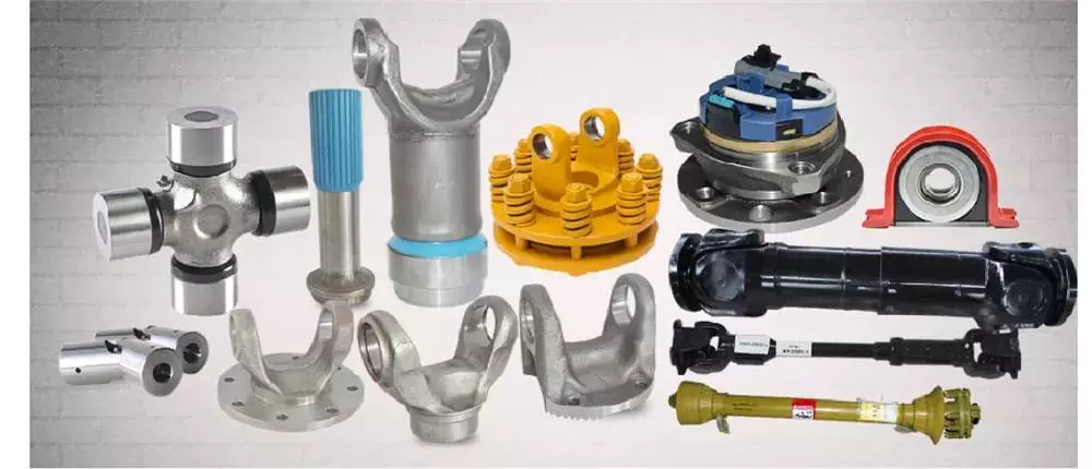
Easy to maintain
Many modern agricultural machines contain computer systems, sensors and other technologies that make them difficult to maintain without the help of experts. While not an impossible task, it does require specific diagnostic software and tools that most manufacturers don't offer to the public. As a result, many farmers do not have access to the tools and diagnostic software needed to repair equipment and must take it to a licensed dealer for repairs.
Fortunately, there are some solutions to this problem. A recent executive order from President Biden, who oversees the federal government, calls for more competition in the economy. His executive order calls on the FTC to limit unfair trade practices and promote U.S. economic growth. One of the recommendations is that consumers have the right to repair farm equipment. Many agricultural products are affected by the new laws as they become more integrated and less competitive, meaning farmers and ranchers are forced to pay more for their produce.
China wholesaler Ce Certificate Europe Hot Sale Lw-7e 30-55HP Tractor 3 Point Hitch Side Shift Hydraulic Backhoe Small Garden Excavator Backhoe near me manufacturer
Product Description
CE certificate Europe hot sale LW-7E 30-55HP Tractor 3 point hitch Side shift Hydraulic Backhoe Small Garden excavator backhoe
LW-7E Side-shift Hydraulic Backhoe Main Features:
- 3 Point Linkage mounted with 2 stabilizing legs and operators seat.
- Side shift to give wider range of digging
- Backhoe is powered by a hydraulic pump run off the tractors PTO.
- Fits different brands tractor by 3-plint hitch
- Self contained hydraulic pump as the power source
- Not a permanent fixture and easy to remove
- Exclusive supporting bracket for 3-point hitch and practical effect
- Arm swing back and shear pins in for secure transporting.
LW-7E Side-shift Hydraulic Backhoe Profile/ Catalogue:
Perfect working performance of our Backhoe:
High quality Backhoe have ISO,CE, PVOC COC, CO etc certificates:
Backhoe Personalized Packing and Transporting Service to meet different customers' demand :
Top-rank technical team and Advance R&D Center :
Advance Production workshop :
Strictly inspect for every set machine before Goods Delivery :
Perfect after-sale service for both Distributors and Private customers:
Please contact us if you have any demand for our Product,
Best price will be quoted for you as soon as receive your Requirement !
Overview of Different Types of Pulleys
A pulley is a wheel mounted on a shaft or shaft. Its purpose is to facilitate the movement or change of direction of the cable or taut rope, and to transmit power between the cable and the shaft. Pulleys are typically used for lifting, winding or forklift applications. If you are building your own pulley system, the following design and installation considerations should be followed. This article will give you an overview of the different types of pulleys.
Pulley System Mechanics
There are many different ways to utilize the mechanism of the pulley system. The most basic pulley system consists of a fixed wheel and a support frame. Both components are connected by ropes or cables used to support the load. A pulley system is effective when the force required to lift the load is less than the weight of the object being lifted.
One way to use a pulley system is to suspend a block with a mass of 0.80 kg on a fixed pulley. Then another person can hang a bucket weighing up to 40kg. The weight of the bucket is transferred to the fixed pulley. The rope is attached to the pulley by a loop or sling. The rope will spin and pull on the barrel or block.
The pulley system is also an important tool for lifting heavy objects. Pulleys are often used in construction equipment to make lifting heavy objects easier. Gun tackles, yard tackles, and stationary tackle systems are common examples of these devices. They use the mechanical advantage of the design to guide the force that lifts the object. If you want to learn more about pulley systems, visit Vedantu. This website will provide you with a full description of the mechanism and its application.
Types of pulleys
Many different types of pulleys are used to lift heavy objects. They change the direction of the force and are an integral part of the cable system. Therefore, pulleys can move large and heavy objects more easily. However, before buying a pulley, you should have an idea of the benefits it brings. Below are some of the most common uses for pulleys.
Conical Pulley: Consists of several small conical pulleys connected to each other. The larger base of 1 pulley is used to guide the force. Round pulleys are used in the same way as step pulleys. They are widely used in industry and can be purchased at any hardware store. Pulleys are a huge investment, and the benefits they provide far outweigh the cost.
Movable Pulls: These are similar to their names, but work by allowing objects to move with the pull. Their movable parts are attached to the object to be lifted. They are also ideal for lifting heavy loads and can be found in utility elevators and construction cranes. They are also used in many other industries. They can also be made of wood, plastic or metal. The type of pulley you use depends on its intended use.
Mechanical Advantages of Pulley Systems
A pulley system is a simple machine that reduces the effort required to lift heavy loads. This mechanical advantage is proportional to the number of loops. For example, if you have a single rope loop, you must apply equal force to lift the weight. When you add another rope loop, you can lift heavier weights just by applying the same force. Therefore, a pulley system is an excellent way to use gravity to your advantage.
Mechanical advantage is a measure of the effectiveness of a pulley system. This ratio of force to work is called the mechanical advantage. In other words, if the rope system has a large mechanical advantage, it means that it requires less force to lift heavier loads. This advantage is usually measured in kilograms and is the same for all pulley systems. In general, the greater the mechanical advantage, the less effort is required to lift the load.
The mechanical advantage of a pulley system is that a single movable pulley requires half the force to lift an object than a single fixed pulley. Assuming frictionless bearings, the MA of a single pulley system is 2, similar to the MA of a single lever. A single pulley travels twice as much as it takes to move heavy objects manually.
Considerations when designing and installing a pulley system
The capacity of the pulley depends on the type and diameter of the cable. Besides its diameter, its sheath should also support it well. The basic function of the pulley is also important. However, most people tend to ignore the pulley selection process, resulting in ineffective load-pull capabilities. To avoid such problems, different parameters must be carefully considered during design and installation.
During the design and installation of the pulley system, the ratio of the cable diameter to the largest pulley diameter must be considered. Those who work in the industrial sector will have an idea of this ratio. The greater the D:d ratio, the greater the capacity of the cable to withstand the load. The best way to ensure secure design is to take the right information and use it to design a system that is both robust and secure.
When designing a pulley system, it is important to remember that the pulley needs to have enough power to operate safely. In addition to horsepower, the belt should have sufficient elongation to absorb shock loads. If the elongation of the belt is very small, it is very likely that the teeth will be sheared or broken, causing serious damage to the system. Extensive belt sag should be compensated for by offsetting the driven pulley. Finally, the frame supporting the pulley should be rigid. Otherwise, the non-rigid frame will cause center distance and tooth skipping changes.
Add more pulleys to the system
Adding more pulleys to the spool might have some effect. The friction between the rope and the pulley increases with the number of pulleys, which in practice limits the number of spools. The best solution is to combine the pulleys into 1 housing. If the load is small enough, adding a few pulleys probably won't make a difference.
Using multiple pulleys allows a single load to be lifted with half the force required. The longer the rope, the greater the mechanical advantage. In fact, a spool can withstand a load of 100 N. Additionally, adding more pulleys quadrupled the mechanical advantage. In this case, a single 100 N load would require a force of 25 Newtons.
When the rope is used, it stretches as the weight of the object increases. This will make the rope longer, increasing its length and increasing the distance over which the load can be lifted. Eventually, the rope will break and the lifted object will fall. Then you will have to buy a new rope. It may seem like an expensive proposition, but it pays off in the long run.
cast iron pulley
Cast iron pulleys are the most popular choice among industrial users. They are made of solid cast iron and usually cost very little. Their rims are held in place by a mesh that extends from a central boss. They also have spokes and arms that hold them in place. These pulleys are ideal for a variety of applications including fan belts, compressors and conveyors.
V-groove drive pulleys are ideal for general purpose pulleys. It has an inner diameter of 1 inch and is commonly used in feeders and ventilation curtain systems. Its steel straps prevent rust and ensure it meets or exceeds industry standards. 3-1/2" cast iron pulleys are also available. In addition to the V-groove drive pulley, there are similar pulleys for power transmission. The V-groove drive pulley is powder coated for added durability.
The cross section of the arm is elliptical, with the long axis twice as long as the short axis. The radius of the arm is equal to the diameter of the pulley. The thickness of the arm is a key factor to consider when purchasing a pulley. If you're not sure which material you need, you can always consider wooden or steel pulleys. They are lighter and have a higher coefficient of friction than metal pulleys.
timing pulley
Plastic timing pulleys have many advantages over steel timing pulleys. On the 1 hand, they are lightweight and corrosion resistant, making them ideal for applications that do not require high torque and tensile strength. Another benefit is their resistance to high temperatures. Plastic timing pulleys are ideal for applications involving flammable gases, solvents or particles. They can last for many years. For more information on the different types of plastic timing pulleys.
Vertical shaft drives require flanged timing pulleys. For large span drives, at least 1 of these pulleys must be flanged. The flange provides a secure connection to the shaft and prevents ratcheting of the timing belt. Finally, HTD timing belt teeth prevent timing belt ratcheting. These teeth need a large enough space to be seated. However, they can also cause a backlash. These pulleys are not suitable for applications where positional accuracy is critical.
Timing belt systems are designed to avoid such problems. The drive shaft and the driven shaft are aligned with each other. The pulleys are located on different planes and are connected by pitch lines. The pitch line of the timing pulley coincides with the pitch line of the belt. These pulleys are also easier to implement and maintain. It is better to use a synchronous system because the resulting gear system emits less noise than other systems.
China manufacturer Mini Garden Tractor Front End Loader Telescopic Boom Wheel Loader with Multifunction Attachments with Free Design Custom
Product Description
4 wheel drive landscaping wheel loader M910 plane bucket front end telescopic loaders for sale
Product Description
1.Heavy duty telescopic boom, self-leveling and boom floating
2.4WD hydrostatic direct drive motors, automatic transmission, high efficiency
3.Quick coupling and quick hitch system
4.Both front and rear hydraulic output for various attachments
5.CZPT engine, Italian pump and valves; EPA Tier4 and EU 5 engines optional
6. 9-functions joystick
7.Flexible articulation and differential lock for all rough terrain
8.Tiltable cabin, fully access to inner parts
Product Parameters
| Model | M910 mini telescopic wheel loader |
| Dimension (LxWxH) | 2690 X1300 X 2280mm |
| Max. lifting height (boom extended) | 3030mm |
| Max. lifting height (boom retracted) | 2512mm |
| Max. dumping height | 2630mm |
| Bucket capacity | 0.5cbm |
| Max. loading capacity | 1000kg |
| Min. turning radius | 2120mm |
| Speed | 0-12 km/h |
| Weight | 1850 kg |
| Standard tire | 26X12-12 |
| Working oil flow | 33.5L/minx2 |
| Engine | Yanmar/Chinese/Euro V/ EPA Tier 4 final |
| Rated power | 45hp |
Detailed Photos
More photos of the Loader
Our Advantages
Loader+Tractor, 1 Multi-purpose helper for all your works
Front part is loader, with telescopic boom, hydraulic output, quick hitch and coupling system for various attachments, like bucket, fork, grapple, auger, hammer, lawn mower, etc.
Rear part is tractor, with hydraulic output, 3-point hitch, hydraulic PTO, for rotary tiller, flail mower, plough, harrow, trailer, etc.
STEEL CZPT series machines are widely used in farming, agriculture, landscaping, gardening, construction, municiple, etc.
Packaging & Shipping
Thanks to the compact design of STEEL CZPT M910 mini telescopic loader, it can be driven into container directly and fully assembled.
Loading condition:2 sets/20ft GP; 4 sets/40ft GP
Company Profile
Direct Manufacturer, 100% guarantee!!
We are direct manufacture factory, every aspect in a deal that customer concerns is guaranteed, like price, quality, delivery time and after service.
We devoted to offering 1 stop shopping and solution to customers' needs. The products we currently offer covering loaders, telehandlers, excatators and loader attachments. Besides we have our own engineering team, can make customized design/product.
"Honest" is our business way. We appreciate customers' trust, and we are always CZPT as return.
We choose "STEEL CAMEL" as our brandname, as all our products were designed for heavy duty work, trouble less and more service, like the what the CZPT do for people.
FAQ:
1. Are you manufacturer?
Yes.
We are factory in CZPT city, ZheJiang province, near HangZhou port.
By fast train to CZPT station, from ZheJiang , 3-4 hours; from ZheJiang , 2-3 hours.
2. Do you have warranty?
Yes.
All machines have 18 months or 1000 hours warranty, whichever comes first
Warranty starts from the time you receive the machines, not include production and shipping time.
Within warranty, all parts are offered for free. Exceed warranty, all parts are offered at cost prices.
3. Do you have after-sale service?
Yes.
After order, we will start production quickly and keep updated.
After shipment, we will track the shipping and keep updated.
After you receive machines, we will instruct the usages and maintenance.
During usage, if any problems, we will offer timely and complete solutions.
We offer servicing for the whole lifetime of machines, no worry for personal use or resell.
How to use the pulley system
Using a pulley system is a great way to move things around your home, but how do you use a pulley system? Let's look at the basic equations that describe a pulley system, the types of pulleys, and some safety considerations when using pulleys. Here are some examples. Don't worry, you'll find all the information you need in 1 place!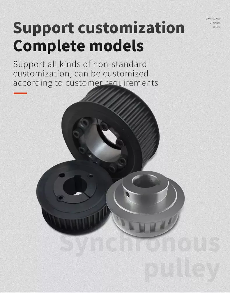
Basic equations of pulley systems
The pulley system consists of pulleys and chords. When the weight of the load is pulled through the rope, it slides through the groove and ends up on the other side. When the weight moves, the applied force must travel nx distance. The distance is in meters. If there are 4 pulleys, the distance the rope will travel will be 2x24. If there are n pulleys, the distance traveled by the weight will be 2n - 1.
The mechanical advantage of the pulley system increases with distance. The greater the distance over which the force is applied, the greater the leverage of the system. For example, if a set of pulleys is used to lift the load, 1 should be attached to the load and the other to the stand. The load itself does not move. Therefore, the distance between the blocks must be shortened, and the length of the line circulating between the pulleys must be shortened.
Another way to think about the acceleration of a pulley system is to think of ropes and ropes as massless and frictionless. Assuming the rope and pulley are massless, they should have the same magnitude and direction of motion. However, in this case the quality of the string is a variable that is not overdone. Therefore, the tension vector on the block is labeled with the same variable name as the pulley.
The calculation of the pulley system is relatively simple. Five mechanical advantages of the pulley system can be found. This is because the number of ropes supporting the load is equal to the force exerted on the ropes. When the ropes all move in the same direction, they have 2 mechanical advantages. Alternatively, you can use a combination of movable and fixed pulleys to reduce the force.
When calculating forces in a pulley system, you can use Newton's laws of motion. Newton's second law deals with acceleration and force. The fourth law tells us that tension and gravity are in equilibrium. This is useful if you need to lift heavy objects. The laws of motion help with calculations and can help you better understand pulley systems.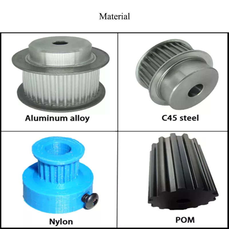
Types of pulleys
Different types of pulleys are commonly used for various purposes, including lifting. Some pulleys are flexible, which means they can move freely around a central axis and can change the direction of force. Some are fixed, such as hinges, and are usually used for heavier loads. Others are movable, such as coiled ropes. Whatever the purpose, pulleys are very useful in raising and lowering objects.
Pulleys are common in many different applications, from elevators and cargo lift systems to lights and curtains. They are also used in sewing machine motors and sliding doors. Garage and patio doors are often equipped with pulleys. Rock climbers use a pulley system to climb rocks safely. These pulley systems have different types of pinions that allow them to balance weight and force direction.
The most common type of pulley is the pulley pulley system. The pulley system utilizes mechanical advantages to lift weight. Archimedes is thought to have discovered the pulley around 250 BC. in ancient Sicily. Mesopotamians also used pulleys, they used ropes to lift water and windmills. Pulley systems can even be found at Stonehenge.
Another type of pulley is called a compound pulley. It consists of a set of parallel pulleys that increase the force required to move large objects. This type is most commonly used in rock climbing and sailing, while composite pulleys can also be found in theater curtains. If you're wondering the difference between these 2 types of pulleys, here's a quick overview:
Mechanical Advantages of Pulley Systems
Pulley systems offer significant mechanical advantages. The ability of the system to reduce the effort required to lift weights increases with the number of rope loops. This advantage is proportional to the number of loops in the system. If the rope had only 1 loop, then a single weight would require the same amount of force to pull. But by adding extra cycles, the force required will be reduced.
The pulley system has the advantage of changing the direction of the force. This makes it easier to move heavy objects. They come in both fixed and mobile. Pulleys are used in many engineering applications because they can be combined with other mechanisms. If you want to know what a pulley can do, read on! Here are some examples. Therefore, you will understand how they are used in engineering.
Single-acting pulleys do not change direction, but compound pulleys do. Their mechanical advantage is six. The compound pulley system consists of a movable pulley and a fixed pulley. The mechanical advantage of the pulley system increases as the number of movable wheels decreases. So if you have 2 wheels, you need twice as much force to lift the same weight because you need a movable pulley.
The mechanical advantage of a pulley system can be maximized by adding more pulleys or rope lengths. For example, if you have a single pulley system, the mechanical advantage is 1 of the smallest. By using 2 or 3 pulleys, up to 5 times the mechanical advantage can be achieved. You can also gain up to 10 times the mechanical advantage by using multiple pulley systems.
The use of a single movable pulley system also adds to the mechanical advantage of the pulley system. In this case, you don't have to change the direction of the force to lift the weight. In contrast, a movable pulley system requires you to move the rope farther to generate the same force. Using a compound pulley system allows you to lift heavy loads with ease.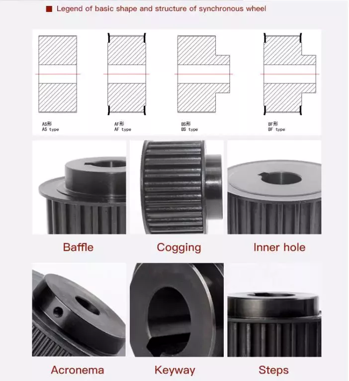
Safety Issues When Using Pulley Systems
Pulleys have an incredibly unique structure, consisting of a disc with a groove in the middle and a shaft running through it. A rope or cord is attached to 1 end of a pulley that turns when force is applied. The other end of the rope is attached to the load. This mechanical advantage means that it is much easier to pull an object using the pulley system than to lift the same object by hand.
Although pulley systems are a common part of many manufacturing processes, some employers do not train their workers to use them properly or install protection to prevent injury. It is important to wear proper PPE and follow standard laboratory safety practices during pulley system activities. Make sure any support structures are strong enough to handle the weight and weight of the rope or rope. If you do fall, be sure to contact your employer immediately.
China Professional Telake Brand Powerful Senior Garden Tool 180HP 200HP 210HP Tractor with Best Sales
Product Description
Product Description:
TK190-210HP series tractor is designed for works on middle-scale farms and auxiliary works on large farm
land. It equips with Chinese famous supercharged engine, 6 cylinders, produces more power and less
fuel consumption, making the work more energy-efficient.
With dynamic and fashionable appearance, flat floor, side console and suspension pedal, HANWO patent
luxury cab, with A/C or heater, provide you a safe, quite and comfortable driving condition.
Standard with enhanced chassis and 16F+8R shuttle shift gearbox, optional creeper type gear shift, to
meet the requirements on more rational speeds;
Equipped with strong pressure device lifter to ensure the best rotary tillage and plowing effect. Force
control, position control or floating control is optional for different conditions.
We use category II type three-point hitch, up to international standard; enhanced lifting arms and
quick-change connectors improve the general strength while matching various implements.
Optional Herringbone tires, radial tires or other type of tires to meet your needs of working conditions;
Main Technical Specifications:
| Model | TK1854 | TK2104 | ||
| Type | 4×4 | 4×4 | ||
|
Overall Dimension |
L×W×H | 5300×2200×3100 | 5300×2300×3100 | |
| Tread | Front Wheel | 1820 | 1820 | |
| Rear Wheel | 1680~ 2380(usual 1800) |
1680~ 2380(usual 1800) |
||
| Wheel Base | 2800 | 2800 | ||
| Min. Ground Base | 450 (the bottom of traction plate) | 470 | ||
| Min. Usage Mass(kg) | 6800 | 6900 | ||
|
Engine |
Model | Weichai WP6G185E330 | Weichai WP6G210E330 | |
| Type | Vertical, water cooled, 4-stroke, turbocharged, intercooled type | |||
| Rated Power(kw) | 136 | 154.4 | ||
| Rated Rev.(r/min) | 2200 | 2200 | ||
| Fuel | Diesel Oil | |||
| Tire | Front Wheel | 16.9-28 | ||
| Rear Wheel | 20.8-38 | |||
| Clutch | Dry-friction, Dual stage, Hydraulic power assisted | |||
| Steering | Hydraulic type | |||
| Transmission Box | 16F+16R synchro shift | |||
| Suspension Type | Post Positioned Three-point Suspension Catalogue III | |||
| PTO | Type and Rev.(r/min) | Post-position, independent type 760/850 | ||
| Spline Size | φ38 Rectangle Spline with 8 teeth | |||
Technology & Innovation:
WeiFang Telake has established a professional R & D team, realized the self-control ability of core components by integrating the industry's
advantageous resources, built a stable quality control system.
Invested tens millions to introduce intelligent mechanization total production line, automatic chassis production line, gearbox processing line and welding
robots, processing centers and other advanced production lines and equipment, to achieve an annual production capacity of 30,000 tractors.
/////////////////////////////////////////////////////////////////////////////////////////////////////////////////////////////////////////////////////////////////////
Packaging & Delivery:
-Delivery time:20- 30 days.
/////////////////////////////////////////////////////////////////////////////////////////////////////////////////////////////////////////////////////////////////////
Certifications:
Common problems
(1) Are you a manufacturing factory or a trading company?
We are a factory with 20 years of professional production experience in the field of 25hp-240hp tractors, located in HangZhou City, ZheJiang Province, China. Our factory has passed ISO9001, CCC, CE, SGS and BV certification. We also have a quality control department to purchase products for customers. This is why the price of our tractors is so reasonable.
(2) Can we print the logo or company name on your product or packaging?
of course. Your logo can be printed on your product by embossing, self-adhesive or silk-screen printing.
(3) About the price
The price is negotiable. It can be changed according to the options or packaging of the tractor.
(4) Regarding payment or other issues
We accept LC, TT, if you have other questions, please email me or chat with me directly.
Contact
Welcome to our factory
Adhere to the business tenet of "Integrity-based, Quality First", and wholeheartedly provide you with the best products and wholehearted service. We actively cooperate with research institutions and multinational companies to achieve continuous innovation. HangZhou Telake Agricultural Equipment CO.,LTD welcomes domestic and foreign customers to visit and guide!
HangZhou Telake Agricultural Equipment CO.,LTD
Adress: East of Xihu (West Lake) Dis. Road,South of Cailin Road,Xihu (West Lake) Dis. Economic District,HangZhou,ZheJiang ,China
How to Identify a Faulty Drive Shaft
The most common problems associated with automotive driveshafts include clicking and rubbing noises. While driving, the noise from the driver's seat is often noticeable. An experienced auto mechanic can easily identify whether the sound is coming from both sides or from 1 side. If you notice any of these signs, it's time to send your car in for a proper diagnosis. Here's a guide to determining if your car's driveshaft is faulty:
Symptoms of Driveshaft Failure
If you're having trouble turning your car, it's time to check your vehicle's driveshaft. A bad driveshaft can limit the overall control of your car, and you should fix it as soon as possible to avoid further problems. Other symptoms of a propshaft failure include strange noises from under the vehicle and difficulty shifting gears. Squeaking from under the vehicle is another sign of a faulty driveshaft.
If your driveshaft fails, your car will stop. Although the engine will still run, the wheels will not turn. You may hear strange noises from under the vehicle, but this is a rare symptom of a propshaft failure. However, you will have plenty of time to fix the problem. If you don't hear any noise, the problem is not affecting your vehicle's ability to move.
The most obvious signs of a driveshaft failure are dull sounds, squeaks or vibrations. If the drive shaft is unbalanced, it is likely to damage the transmission. It will require a trailer to remove it from your vehicle. Apart from that, it can also affect your car's performance and require repairs. So if you hear these signs in your car, be sure to have it checked by a mechanic right away.
Drive shaft assembly
When designing a propshaft, the design should be based on the torque required to drive the vehicle. When this torque is too high, it can cause irreversible failure of the drive shaft. Therefore, a good drive shaft design should have a long service life. Here are some tips to help you design a good driveshaft. Some of the main components of the driveshaft are listed below.
Snap Ring: The snap ring is a removable part that secures the bearing cup assembly in the yoke cross hole. It also has a groove for locating the snap ring. Spline: A spline is a patented tubular machined element with a series of ridges that fit into the grooves of the mating piece. The bearing cup assembly consists of a shaft and end fittings.
U-joint: U-joint is required due to the angular displacement between the T-shaped housing and the pinion. This angle is especially large in raised 4x4s. The design of the U-joint must guarantee a constant rotational speed. Proper driveshaft design must account for the difference in angular velocity between the shafts. The T-bracket and output shaft are attached to the bearing caps at both ends.
U-joint
Your vehicle has a set of U-joints on the driveshaft. If your vehicle needs to be replaced, you can do it yourself. You will need a hammer, ratchet and socket. In order to remove the U-joint, you must first remove the bearing cup. In some cases you will need to use a hammer to remove the bearing cup, you should be careful as you don't want to damage the drive shaft. If you cannot remove the bearing cup, you can also use a vise to press it out.
There are 2 types of U-joints. One is held by a yoke and the other is held by a c-clamp. A full ring is safer and ideal for vehicles that are often used off-road. In some cases, a full circle can be used to repair a c-clamp u-joint.
In addition to excessive torque, extreme loads and improper lubrication are common causes of U-joint failure. The U-joint on the driveshaft can also be damaged if the engine is modified. If you are driving a vehicle with a heavily modified engine, it is not enough to replace the OE U-joint. In this case, it is important to take the time to properly lubricate these components as needed to keep them functional.
tube yoke
QU40866 Tube Yoke is a common replacement for damaged or damaged driveshaft tubes. They are desirably made of a metallic material, such as an aluminum alloy, and include a hollow portion with a lug structure at 1 end. Tube yokes can be manufactured using a variety of methods, including casting and forging. A common method involves drawing solid elements and machining them into the final shape. The resulting components are less expensive to produce, especially when compared to other forms.
The tube fork has a connection point to the driveshaft tube. The lug structure provides attachment points for the gimbal. Typically, the driveshaft tube is 5 inches in diameter and the lug structure is 4 inches in diameter. The lug structure also serves as a mounting point for the drive shaft. Once installed, Tube Yoke is easy to maintain. There are 2 types of lug structures: 1 is forged tube yoke and the other is welded.
Heavy-duty series drive shafts use bearing plates to secure the yoke to the U-joint. All other dimensions are secured with external snap rings. Yokes are usually machined to accept U-bolts. For some applications, grease fittings are used. This attachment is more suitable for off-road vehicles and performance vehicles.
end yoke
The end yoke of the drive shaft is an integral part of the drive train. Choosing a high-quality end yoke will help ensure long-term operation and prevent premature failure. Pat's Driveline offers a complete line of automotive end yokes for power take-offs, differentials and auxiliary equipment. They can also measure your existing parts and provide you with high quality replacements.
A U-bolt is an industrial fastener with threaded legs. When used on a driveshaft, it provides greater stability in unstable terrain. You can purchase a U-bolt kit to secure the pinion carrier to the drive shaft. U-bolts also come with lock washers and nuts. Performance cars and off-road vehicles often use this type of attachment. But before you install it, you have to make sure the yoke is machined to accept it.
End yokes can be made of aluminum or steel and are designed to provide strength. It also offers special bolt styles for various applications. CZPT's drivetrain is also stocked with a full line of automotive flange yokes. The company also produces custom flanged yokes for many popular brands. Since the company has a comprehensive line of replacement flange yokes, it can help you transform your drivetrain from non-serviceable to serviceable.
bushing
The first step in repairing or replacing an automotive driveshaft is to replace worn or damaged bushings. These bushings are located inside the drive shaft to provide a smooth, safe ride. The shaft rotates in a rubber sleeve. If a bushing needs to be replaced, you should first check the manual for recommendations. Some of these components may also need to be replaced, such as the clutch or swingarm.