Product Description
Product Description
Product description:
planetary reducer gearbox is designed with large torque and transmission efficiency, low-speed stability, compact radial size, low noise, etc.
The main devices we are making are walking reducers, lifting reducers and swing reducers.
They are widely used for Truck ,vehicle cranes, crawler cranes, truck mounted cranes, marine cranes, aerial work trucks, excavators, etc.
If above drawing and specifications not suit you,we also can custom according to your specifications,welcome to contact me.
Above reducers we all have stock,will ship out very soon.
Main Products
Our factory mainly produce high quality hydraulic winch,electric winch,hydraulic motor ,gearbox,slewing drive reducers,final drive reducers,we also can custom according to your specifications.if need more information ,pls contact us for the whole product catalog.
Company Profile
CHINAMFG Chuangdong New Material Technology Co., Ltd. is located in CHINAMFG City, ZheJiang Province, China. The factory was establishedin 2008 and specializes in the research and development of planetary transmission technology products. The factory has completeequipment and strong processing capabilities, including boring machines, machining centers, gear shapers, CNC lathes, drillingmachines, and other processing equipment. In addition, the inspection and testing equipment is complete, with main inspectionmethods such as metallographic and physicochemical examination, gear inspection, and finished product loading experiments.
The factory has successively developed a series of planetary transmission mechanisms in the fields of lifting machinery,
exploration machinery, obstacle clearance machinery, aerial work vehicle machinery , marine machinery, petroleum machinery, and truck mounted cranes. At present, our companys main products include 8-100 ton hoisting and slewing mechanisms for truck cranes,16-100 ton walking mechanisms for crawler cranes, 18-30 meter hoisting and slewing mechanisms for aerial work vehicles, 6-25 ton hydraulic winches and slewing mechanisms for truck mounted cranes, and 1.5-30 ton IYJ series hydraulic winches widely used in obstacle clearing machinery, marine machinery, and petroleum machinery. The company actively cooperates with various main engine manufacturers to develop products, and also cooperates with ZheJiang Machinery Design Institute, ZheJiang University, HangZhou
University of Technology and other universities to develop a series of refined and new products, which have won recognition fromthe vast market.
In recent years, with the development and growth of domestic construction machinery, the company has closely followed the marketsituation, vigorously invested in equipment, built standardized factories, and continuously expanded and strengthened the companys scale.
We welcome your cooperation.
Packaging & Shipping
package:wooden boxes
shipping:by sea/rail/road or as required
Products Application
FAQ
Q1:What's you MOQ?
A:MOQ is 1 piece.
Q2:Do you have catalog?
yes,pls contact us for the catalog
Q3 how to ship?
ship by sear/according to your request.
Q4;If the reducer are not the 1 you need,what should do?
Pls send us drawing and specifications you need,then we custom according to your request.
/* January 22, 2571 19:08:37 */!function(){function s(e,r){var a,o={};try{e&&e.split(",").forEach(function(e,t){e&&(a=e.match(/(.*?):(.*)$/))&&1
| Application: | Motor, Electric Cars, Motorcycle, Machinery, Marine, Toy, Agricultural Machinery, Car |
|---|---|
| Hardness: | Hardened Tooth Surface |
| Installation: | Horizontal Type |
| Layout: | Coaxial |
| Gear Shape: | Cylindrical Gear |
| Step: | Three-Step |
| Customization: |
Available
| Customized Request |
|---|

Can gear reducers be customized for specific industrial needs and requirements?
Yes, gear reducers can be customized to meet specific industrial needs and requirements. Manufacturers offer customization options to ensure that gear reducers are tailored to the unique demands of various applications:
1. Gear Ratio Selection: Gear reducers can be designed with specific gear ratios to achieve the desired speed reduction or increase, catering to the specific requirements of the machinery or equipment.
2. Shaft Configurations: Gear reducers can be configured with different shaft sizes, lengths, and orientations to fit seamlessly into existing systems or accommodate specific mounting arrangements.
3. Torque Capacity: Customized gear reducers can be designed to handle higher or lower torque loads based on the application's operational requirements.
4. Environmental Considerations: Gear reducers can be customized with special coatings, materials, or seals to withstand harsh environments, extreme temperatures, or corrosive conditions.
5. Noise and Vibration Reduction: Custom designs can incorporate features to reduce noise and dampen vibrations, enhancing the overall operation and user experience.
6. Mounting and Connection Options: Manufacturers can adapt gear reducer designs to include specific mounting interfaces or connection methods that align with the equipment's design.
7. Lubrication and Maintenance: Customized gear reducers can include features for easy maintenance, such as accessible lubrication points or monitoring systems.
8. Integration with Controls: Gear reducers can be customized to integrate seamlessly with control systems, sensors, or automation processes, enhancing system efficiency and performance.
By collaborating with manufacturers and providing detailed specifications, industries can obtain tailor-made gear reducers that address their specific operational needs and contribute to the success of their applications.

What factors should be considered when selecting the right gear reducer?
Choosing the appropriate gear reducer involves considering several crucial factors to ensure optimal performance and efficiency for your specific application:
- 1. Torque and Power Requirements: Determine the amount of torque and power your machinery needs for its operation.
- 2. Speed Ratio: Calculate the required speed reduction or increase to match the input and output speeds.
- 3. Gear Type: Select the appropriate gear type (helical, bevel, worm, planetary, etc.) based on your application's torque, precision, and efficiency requirements.
- 4. Mounting Options: Consider the available space and the mounting configuration that suits your machinery.
- 5. Environmental Conditions: Evaluate factors such as temperature, humidity, dust, and corrosive elements that may impact the gear reducer's performance.
- 6. Efficiency: Assess the gear reducer's efficiency to minimize power losses and improve overall system performance.
- 7. Backlash: Consider the acceptable level of backlash or play between gear teeth, which can affect precision.
- 8. Maintenance Requirements: Determine the maintenance intervals and procedures necessary for reliable operation.
- 9. Noise and Vibration: Evaluate noise and vibration levels to ensure they meet your machinery's requirements.
- 10. Cost: Compare the initial cost and long-term value of different gear reducer options.
By carefully assessing these factors and consulting with gear reducer manufacturers, engineers and industry professionals can make informed decisions to select the right gear reducer for their specific application, optimizing performance, longevity, and cost-effectiveness.

Are there variations in gear reducer designs for specific tasks and applications?
Yes, gear reducer designs vary widely to suit specific tasks and applications across various industries. Manufacturers offer a range of gear reducer types and configurations to accommodate different requirements, including:
- Helical Gear Reducers: These are versatile and provide smooth and efficient torque transmission. They are commonly used in applications requiring high precision and moderate speed reduction, such as conveyors, mixers, and agitators.
- Bevel Gear Reducers: These are ideal for transmitting power between intersecting shafts. They are often used in heavy machinery, printing presses, and automotive applications.
- Worm Gear Reducers: These provide compact solutions and are suitable for applications with higher speed reduction requirements, such as conveyor systems, winches, and elevators.
- Planetary Gear Reducers: These offer high torque density and are used in applications demanding precise control, such as robotics, aerospace, and heavy-duty machinery.
- Parallel Shaft Gear Reducers: Commonly used in industrial machinery, these reducers are designed for high torque and reliability.
- Right-Angle Gear Reducers: These are used when space limitations require a change in shaft direction, commonly found in packaging equipment and conveyors.
Each type of gear reducer has unique features and benefits that make it suitable for specific tasks. Manufacturers often provide customization options to tailor gear reducers to the precise requirements of an application, including gear ratios, mounting options, and input/output configurations.
Therefore, the variation in gear reducer designs allows industries to select the most appropriate type based on factors such as torque, speed, space constraints, precision, and environmental conditions.


editor by CX 2024-02-29
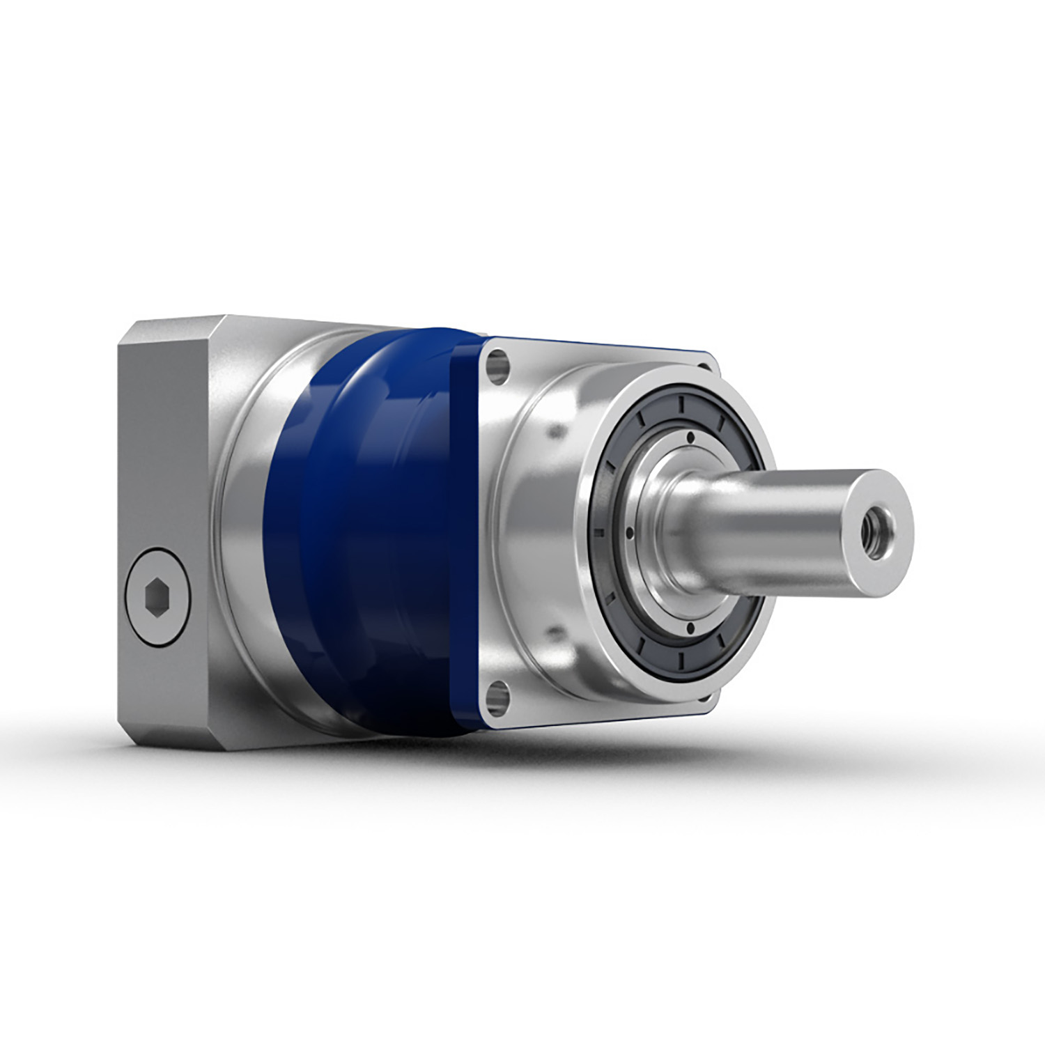
China wholesaler Planetary Gearbox Gear Box Reduction Housing Speed Reducer Epicyclic Motor Transmission Machine Hydraulic Best Price Unit Servo Gearbox Planetary Gearboxes gearbox drive shaft
Product Description
Planetary Gearbox gear box reduction gearbox speed reducer epicyclic motor transmission machine housing best price unit servo hydraulic Planetary Gearboxes
Planetary Gearboxes is an old mechanics fundamental that is still being used for new leading innovative technology like 3D printing, and new methods of transport. The planetary gearbox is 1 in which the output and input shafts are aligned. Its basic function is to transfer the maximum amount of torque with the least amount of space. The gear system consists of a reduction state, an acceleration mode, and coupling. No 1 knows who invented the planetary gearbox, but it has been in use since the 15th century. The planetary gear gets its name from the way it looks while it functions. There is a sun gear in the middle attached to ring gears. As the sun gear rotates, it also moves the ring gears. The sun gears are called input shaft, whereas the carrier and ring gears are called output.
The planetary gearbox works in the ratios from 1.5:1 to 12000:1. In a 3:1 system, there are 3 ring gears and 1 sun gear and is called a one-stage planetary gearbox. In ratios of above 5:1, a two-stage planetary gearbox is used. In a 3:1 system, the sun gear is very big, compared to the ring gear, and in the 10:1 system, the sun gear is much smaller than the ring gears. The ratios are in absolute integers. The planetary gearbox system is very precisely placed together, but it still creates friction due to the moving parts inside - sun gear and ring gear. These need lubrication from time to time from oil, gel, or grease. This requirement is present in most moving mechanical machines.
To know what a planetary gearbox does? And it's advantages? Check our blog here -
There are many showcased benefits of using a gearbox like- three-fold torque compared to the normal gearbox, absolute ratios, low inertia, high efficiency, closed system, etc. The planetary gearbox has its applications in many places. It can be used to increase torque in a robot, to reduce speed in printing press rollers, for positioning, and in packaging machines to name a few.
Buying a gearbox depends on the planned use of the gearbox. There are a certain number of things to keep in mind like - torque, backlash, ratio, corrosion, resistance, noise level, delivery time, price, and availability. There might be other requirements that are different for each buyer.
A planetary gearbox is a medieval tool reincarnated in modern form. That itself says a lot about the usefulness and application of the device. It's an efficient device for the work it performs and has stood the test of time, without getting obsolete.
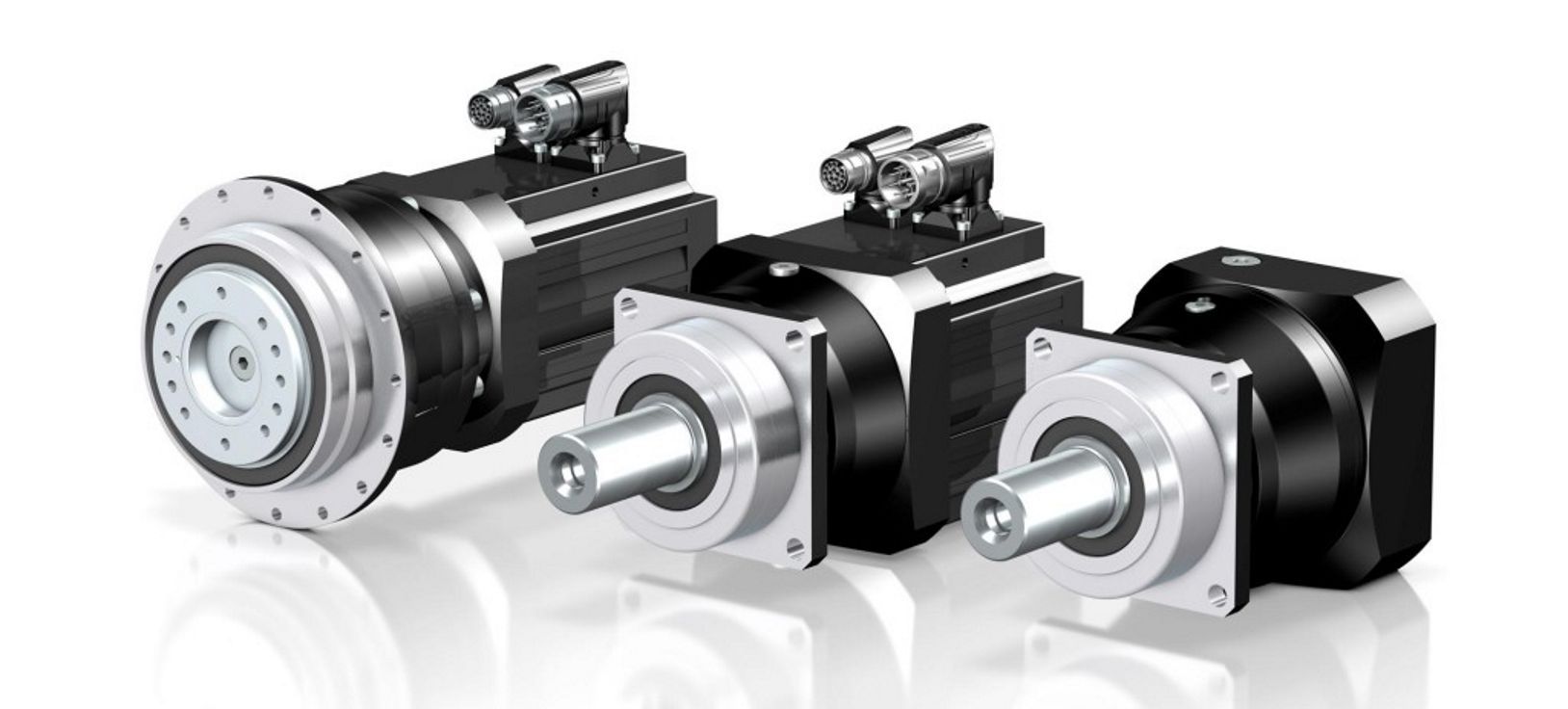
Manufacturer of Planetary Gearbox, Planetary gear reducer, Planetary geared motor, Epicyclic gearing, Planetary gearing, Gearboxes, can interchange and replacement with CHINAMFG gearbox, CHINAMFG brown gearbox and so on.
/* March 10, 2571 17:59:20 */!function(){function s(e,r){var a,o={};try{e&&e.split(",").forEach(function(e,t){e&&(a=e.match(/(.*?):(.*)$/))&&1
| Application: | Motor, Electric Cars, Machinery, Agricultural Machinery |
|---|---|
| Hardness: | Hardened Tooth Surface |
| Installation: | Horizontal Type |
| Layout: | Coaxial |
| Step: | Four-Step |
| Output Torque: | 14nm-2000nm |
| Samples: |
US$ 9999/Piece
1 Piece(Min.Order) | |
|---|
Compatibility of Servo Gearbox with a Specific Motor
The compatibility between a servo gearbox and a specific motor depends on several key factors:
1. Mounting Configuration: The mounting interface of the servo gearbox and motor must be compatible. This includes the type of coupling, flange size, and bolt pattern. Proper alignment ensures efficient power transmission and minimizes mechanical stress.
2. Shaft Diameter and Keyway: The diameter and keyway of the motor shaft must match the input shaft of the servo gearbox. A precise fit prevents slippage and ensures accurate torque transmission.
3. Torque and Speed Ratings: The torque and speed requirements of the application should align with the torque and speed ratings of both the motor and gearbox. Oversizing or undersizing either component can lead to inefficient operation and premature wear.
4. Inertia Matching: Inertia matching between the motor and gearbox helps prevent resonance and oscillations in the system. An appropriate inertia match ensures smooth and precise motion control.
5. Backlash and Stiffness: The gearbox's backlash (play in the gears) and stiffness characteristics should match the application's requirements. Low backlash and high stiffness are crucial for accurate positioning tasks.
6. Efficiency and Heat Dissipation: The combined efficiency of the motor and gearbox affects the overall system efficiency. Inadequate efficiency can lead to energy losses and excessive heat generation.
7. Service Life and Maintenance: Compatibility also involves considering the expected service life and maintenance requirements. A well-matched motor-gearbox combination enhances the durability and reliability of the motion control system.
8. Control and Feedback: The control system's capabilities, such as closed-loop control and feedback devices, play a role in determining compatibility. The motor and gearbox should provide the necessary interfaces for effective integration into the control system.
Manufacturers and engineers often provide guidelines and compatibility charts to assist in selecting the right servo gearbox for a specific motor. Considering these factors ensures optimal performance, efficiency, and longevity of the motion control system.

Real-World Examples of Products Using Servo Gearboxes
Servo gearboxes find application in various industries and products, contributing to their precision, efficiency, and performance:
- Industrial Robots: Industrial robots utilize servo gearboxes to achieve precise and controlled movements, enabling tasks such as assembly, welding, and material handling.
- CNC Machines: Computer Numerical Control (CNC) machines use servo gearboxes for accurate positioning and control of cutting tools, resulting in high-quality and complex machining operations.
- Automated Packaging Machines: Servo gearboxes play a vital role in packaging machines by ensuring precise filling, sealing, and labeling of products, leading to consistent packaging quality.
- Medical Devices: Advanced medical devices like robotic surgical systems use servo gearboxes to provide surgeons with precise control and dexterity during minimally invasive procedures.
- Textile Machinery: Servo gearboxes are employed in textile machinery to control the movement of yarn, ensuring uniform and high-quality fabric production.
- Automated Material Handling Systems: Servo gearboxes enable automated conveyors, lifts, and sorting systems to handle materials efficiently and accurately in warehouses and distribution centers.
- Printers and Plotters: High-resolution printers and plotters use servo gearboxes to precisely position print heads and ensure accurate image reproduction.
- Food Processing Equipment: Servo gearboxes are integrated into food processing machines for tasks like slicing, portioning, and mixing, ensuring consistent product quality and yield.
- Pharmaceutical Manufacturing: Pharmaceutical machinery relies on servo gearboxes for precise dosage and filling operations, crucial for drug production.
- Aerospace Components: Aerospace systems, such as landing gear mechanisms and control surfaces, use servo gearboxes to achieve precise movement and ensure the safety of flight.
These examples demonstrate the widespread adoption of servo gearboxes across various industries, where precision, accuracy, and controlled motion are critical for efficient and high-performance operations.
Servo Gearboxes vs. Standard Gearboxes in Industrial Applications
Servo gearboxes and standard gearboxes serve distinct roles in industrial applications. Here's how they differ:
Precision Control: Servo gearboxes are specifically designed for precise motion control in applications that require accurate speed and position control. Standard gearboxes, while also providing speed reduction or torque multiplication, may not offer the same level of precision.
Backlash: Servo gearboxes are designed to minimize backlash, which is crucial for applications where even slight lost motion is unacceptable. Standard gearboxes may have higher levels of backlash due to their broader design scope.
Dynamic Response: Servo gearboxes excel in dynamic response, enabling quick changes in speed and direction with minimal overshoot. Standard gearboxes may not offer the same level of responsiveness.
High Efficiency: Servo gearboxes are optimized for efficiency to ensure precise power transmission. Standard gearboxes may prioritize other factors like cost or load capacity.
Positioning Accuracy: Servo gearboxes are essential for achieving high positioning accuracy in applications such as robotics and CNC machines. Standard gearboxes might not meet the same accuracy requirements.
Load Distribution: Servo gearboxes distribute loads evenly across gear teeth to enhance durability and minimize wear. Standard gearboxes might not have the same load distribution capabilities.
Compact Design: Servo gearboxes are often designed with a compact form factor to fit within tight spaces. Standard gearboxes might be larger and less optimized for space constraints.
Customization: Servo gearboxes can be highly customizable in terms of size, reduction ratio, and mounting options. Standard gearboxes may offer fewer customization choices.
Application Focus: Servo gearboxes are intended for applications that demand precision and responsiveness, such as robotics, automation, and CNC machining. Standard gearboxes are used in a broader range of applications where precision might not be as critical.
In summary, servo gearboxes are specialized components tailored for high-precision motion control applications, while standard gearboxes serve a wider variety of industrial needs with a focus on durability, load handling, and basic speed reduction.
editor by CX 2024-01-26
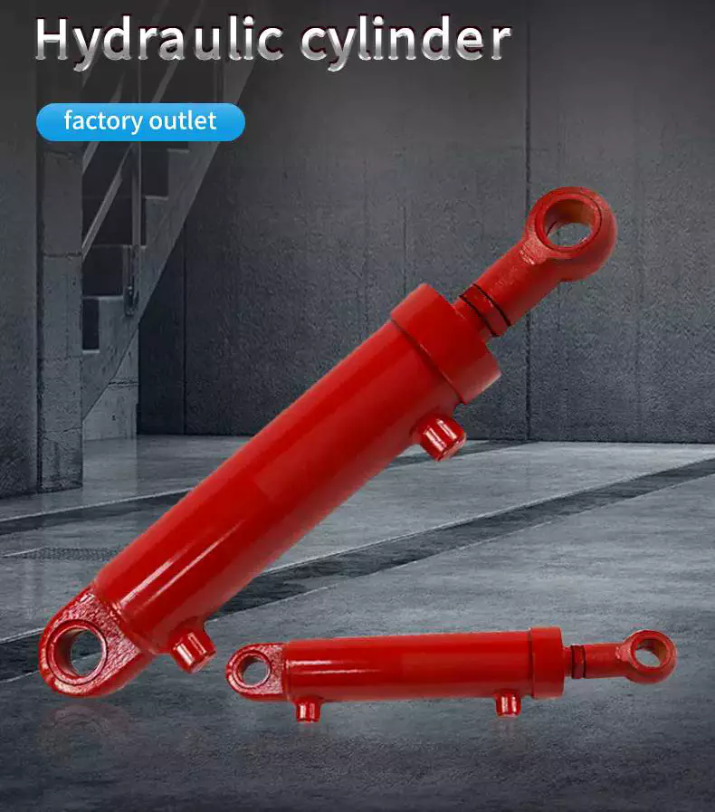
China OEM CZPT Damping Hydraulic Cylinder for Pile Drive Random Chaneel vacuum pump design
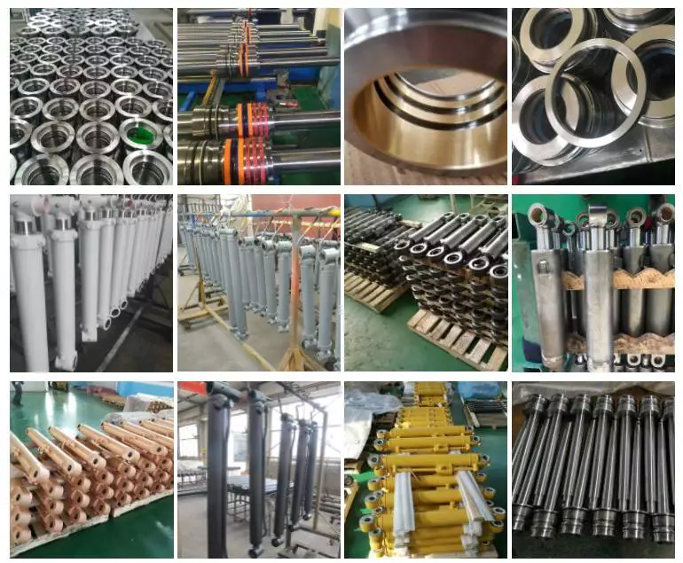
Product Description
Specifications:
| Product Name | HSG Series Hydraulic Cylinder |
| Work Press | 7/14/16/21/31.5MPa 37.5/63MPa Can be Customized |
| Material | Aluminum, Cast Iron,45mnb Steel, Stainless Steel |
| Bore Size | 40mm--320mm, Customizable |
| Shaft Diameter | 20mm--220mm, Customizable |
| Stroke Length | 30mm--14100mm, Customizable |
| Rod Surface Hardness | HRC48-54 |
| Operating Temperature | -40°C to +120 °C |
| Paint Color | Black, Yellow, Blue, Brown, Customizable |
| Service | OEM&ODM |
| Warranty | 1 Year |
| MOQ | 1 Piece |
| Delivery Time | 7-15 Days, Also depending on specific demands |
| Certification | ISO9001,CE |
| Capacity | 50,000Pcs per year |
Product Display:
Mounting:
Working Flow: About Us
Tongte designs and manufactures durable, heavy-duty hydraulic products and accessories and offers lifecycle services to them. We constantly develop our machine base and operations to meet customer-specific needs and remain leaders in the industry. Beyond all else, we want to be the trusted, groundbreaking partner our customers truly need.
In addition to the customized cylinders, CHINAMFG offers hydraulic power units, Electric-Hydraulic linear actuators, piston accumulators, system configurations, and versatile services such as repair and manufacturing services. The modern production facilities are located in HangZhou, ZheJiang (China) where production started in 2001. The core values of Tongke guiding its business strongly are commitment, sustainability, interaction, and customer-first.
We possess over 20 years of experience in the industry and extensive global market experience, our customers are located all over the world, and we truly commit to the customers' needs - these are the success factors of our family-owned company. Our vision is to grow and expand the business further into global markets.
FAQ:
Q1: What does your company do?
A: we are a supplier of high-quality hydraulic products including Hydraulic Cylinders, Hydraulic Power packs, Hydraulic Linear, and other Hydraulic components.
Q2:Are you a manufacturer or trading company?
A: We are a manufacturer.
Q3:Are you able to make Non-standard or customized products?
A: Yes, we can.
Q3: How long is your delivery time?
A: Normally, the delivery time is 7 days if we have stock, and 15-30 working days if we don't. but it
also depends on the product
requirements and quantity.
Q4: Do you provide samples? are the samples free or not?
A: Yes, we can provide samples, but they are not free of charge.
Q5: What are your payment terms?
A: 30% deposit T/T or Irrevocable L/C at sight, If you have any questions, please feel free to
contact us.
Q6: What is your warranty policy?
A: All our products are warranted for 1 full year from the date of delivery against defects in materials and workmanship. Each individual product will be strictly inspected on our factory QC Process
System before shipment. We also have a Customer Service team to respond to customers' questions within 12 hours.
| Certification: | ISO9001 |
|---|---|
| Pressure: | High Pressure |
| Work Temperature: | Normal Temperature |
| Customization: |
Available
|
|
|---|
.shipping-cost-tm .tm-status-off{background: none;padding:0;color: #1470cc}
|
Shipping Cost:
Estimated freight per unit. |
about shipping cost and estimated delivery time. |
|---|
| Payment Method: |
|
|---|---|
|
Initial Payment Full Payment |
| Currency: | US$ |
|---|
| Return&refunds: | You can apply for a refund up to 30 days after receipt of the products. |
|---|
How do hydraulic cylinders enhance the performance of construction and mining equipment?
Hydraulic cylinders play a vital role in enhancing the performance of construction and mining equipment by providing powerful and precise linear motion. These industries require heavy-duty machinery that can withstand demanding conditions and efficiently perform tasks such as lifting, pushing, and digging. Here's a detailed explanation of how hydraulic cylinders enhance the performance of construction and mining equipment:
1. Power and Force:
- Hydraulic cylinders are capable of generating substantial force, allowing construction and mining equipment to handle heavy loads and perform challenging tasks. The hydraulic system applies pressure to the fluid, which is transmitted to the hydraulic cylinder, resulting in the movement of the piston rod. The larger the diameter of the cylinder, the greater the force that can be generated. Hydraulic cylinders enable the equipment to exert significant force, making it possible to lift and move heavy materials, excavate soil and rock, and perform other demanding operations.
2. Precise Control:
- Hydraulic cylinders offer precise control over the movement of construction and mining equipment. By regulating the flow of hydraulic fluid into and out of the cylinder through control valves, operators can precisely control the speed, position, and force exerted by the hydraulic cylinder. This level of control allows for accurate and controlled movements, enabling operators to perform tasks with precision and efficiency. Whether it's lifting a specific load, positioning an attachment, or maneuvering in tight spaces, hydraulic cylinders provide the necessary control for optimal equipment performance.
3. Adaptability:
- Hydraulic cylinders are highly adaptable to various construction and mining equipment. They can be designed and manufactured in different sizes, stroke lengths, and configurations to suit specific requirements. Hydraulic cylinders can be integrated into different types of equipment, such as excavators, loaders, bulldozers, and drilling rigs. Their adaptability allows for the customization of equipment to meet the needs of different applications and operating conditions, enhancing overall performance.
4. Durability and Reliability:
- Construction and mining environments are known for their harsh conditions, including extreme temperatures, vibrations, and exposure to dust, dirt, and debris. Hydraulic cylinders are designed to withstand these challenging conditions and provide long-lasting performance. They are constructed using robust materials, such as high-strength steel, and equipped with seals and components that can endure heavy loads, impacts, and contaminants. The durability and reliability of hydraulic cylinders ensure that construction and mining equipment can operate continuously and withstand the demanding nature of these industries.
5. Safety:
- Hydraulic cylinders contribute to the safety of construction and mining equipment operations. Their precise control allows operators to perform tasks with accuracy, minimizing the risk of accidents and damage to the equipment or surrounding structures. Hydraulic cylinders also enable the implementation of safety features, such as overload protection systems and emergency stop mechanisms, ensuring the safe operation of the equipment. The reliable and controlled movements provided by hydraulic cylinders enhance overall safety in construction and mining operations.
6. Increased Productivity:
- By providing the necessary power, precise control, and adaptability, hydraulic cylinders contribute to increased productivity in construction and mining applications. Construction and mining equipment equipped with hydraulic cylinders can perform tasks more efficiently and effectively, reducing the time and effort required to complete projects. The ability to handle heavy loads, control movements precisely, and adapt to various tasks improves the overall productivity of the equipment, leading to cost savings and improved project timelines.
In summary, hydraulic cylinders enhance the performance of construction and mining equipment by providing power, precise control, adaptability, durability, and safety. They enable these machines to handle heavy loads, perform tasks with accuracy, withstand harsh conditions, and increase productivity. Hydraulic cylinders are integral components that contribute to the efficiency and effectiveness of construction and mining operations.
Impact of Hydraulic Cylinders on Overall Productivity of Manufacturing Operations
Hydraulic cylinders play a crucial role in enhancing the overall productivity of manufacturing operations. These versatile devices are widely used in various industrial applications due to their ability to generate powerful and controlled linear motion. Let's explore how hydraulic cylinders impact the overall productivity of manufacturing operations:
- Powerful Force Generation: Hydraulic cylinders are capable of generating high forces, which enables them to handle heavy loads and perform demanding tasks. By providing the necessary force, hydraulic cylinders facilitate efficient and effective operation of machinery and equipment in manufacturing processes. This ability to exert substantial force contributes to increased productivity by enabling the handling of larger workpieces, enhancing process efficiency, and reducing manual labor requirements.
- Precision and Control: Hydraulic cylinders offer precise control over the movement of loads, allowing for accurate positioning, alignment, and repetitive tasks. The smooth and controlled linear motion provided by hydraulic cylinders ensures precise operation in manufacturing processes, such as assembly, material handling, and machining. This precision and control minimize errors, rework, and scrap, leading to improved productivity and higher-quality output.
- Speed and Efficiency: Hydraulic cylinders can operate at high speeds, enabling rapid movement and cycle times in manufacturing operations. The combination of high force and speed allows for faster operation of machinery and equipment, reducing production cycle times and increasing overall throughput. By optimizing the speed and efficiency of manufacturing processes, hydraulic cylinders contribute to improved productivity and output.
- Flexibility and Adaptability: Hydraulic cylinders are highly flexible and adaptable to different manufacturing applications. They can be customized to meet specific requirements, such as load capacity, stroke length, and mounting options. This versatility allows hydraulic cylinders to be integrated into a wide range of machinery and equipment, accommodating diverse manufacturing needs. The ability to adapt to different tasks and environments enhances overall productivity by enabling efficient utilization of resources and facilitating process optimization.
- Reliability and Durability: Hydraulic cylinders are known for their robustness and durability, making them suitable for demanding manufacturing environments. Their ability to withstand heavy loads, repeated use, and harsh operating conditions ensures reliable performance over extended periods. Minimizing downtime due to cylinder failure or maintenance requirements contributes to increased productivity and uninterrupted manufacturing operations.
In summary, hydraulic cylinders have a significant impact on the overall productivity of manufacturing operations. Their powerful force generation, precision and control, speed and efficiency, flexibility and adaptability, as well as reliability and durability, contribute to optimized processes, increased throughput, improved quality, and reduced labor requirements. By leveraging the capabilities of hydraulic cylinders, manufacturers can enhance productivity, streamline operations, and achieve greater efficiency in their manufacturing processes.
What are the common signs of wear or leakage that indicate hydraulic cylinder issues?
Hydraulic cylinders are critical components in hydraulic systems, and wear or leakage can lead to performance issues and potential system failures. It is important to be aware of the common signs that indicate hydraulic cylinder problems. Here's a detailed explanation of the common signs of wear or leakage that indicate hydraulic cylinder issues:
1. Fluid Leakage:
- Fluid leakage is one of the most obvious signs of hydraulic cylinder problems. If you notice hydraulic fluid leaking from the cylinder, it indicates a seal failure or damage to the cylinder. Leaking fluid may be visible around the rod, piston, or cylinder body. It is important to address fluid leakage promptly as it can lead to a loss of system efficiency, contamination of the surrounding environment, and potential damage to other system components.
2. Reduced Performance:
- Wear or internal damage to the hydraulic cylinder can result in reduced performance. You may notice a decrease in the cylinder's force output, slower operation, or difficulty in extending or retracting the cylinder. Reduced performance can be indicative of worn seals, damaged piston or rod, internal leakage, or contamination within the cylinder. Any noticeable decrease in the cylinder's performance should be inspected and addressed to prevent further damage or system inefficiencies.
3. Abnormal Noise or Vibrations:
- Unusual noise or vibrations during the operation of a hydraulic cylinder can indicate internal wear or damage. Excessive noise, knocking sounds, or vibrations that are not typical for the system may suggest problems such as worn bearings, misalignment, or loose internal components. These signs should be investigated to identify the source of the issue and take appropriate corrective measures.
4. Excessive Heat:
- Overheating of the hydraulic cylinder is another sign of potential issues. If the cylinder feels excessively hot to the touch during normal operation, it may indicate problems such as internal leakage, fluid contamination, or inadequate lubrication. Excessive heat can lead to accelerated wear, reduced efficiency, and overall system malfunctions. Monitoring the temperature of the hydraulic cylinder is important to detect and address potential problems.
5. External Damage:
- Physical damage to the hydraulic cylinder, such as dents, scratches, or bent rods, can contribute to wear and leakage issues. External damage can compromise the integrity of the cylinder, leading to fluid leakage, misalignment, or inefficient operation. Regular inspection of the cylinder's external condition is essential to identify any visible signs of damage and take appropriate actions.
6. Seal Failure:
- Hydraulic cylinder seals are critical components that prevent fluid leakage and maintain system integrity. Signs of seal failure include fluid leakage, reduced performance, and increased friction during cylinder operation. Damaged or worn seals should be replaced promptly to prevent further deterioration of the cylinder's performance and potential damage to other system components.
7. Contamination:
- Contamination within the hydraulic cylinder can cause wear, damage to seals, and overall system inefficiencies. Signs of contamination include the presence of foreign particles, debris, or sludge in the hydraulic fluid or visible damage to seals and other internal components. Regular fluid analysis and maintenance practices should be implemented to prevent contamination and address any signs of contamination promptly.
8. Irregular Seal Wear:
- Hydraulic cylinder seals can wear over time due to friction, pressure, and operating conditions. Irregular seal wear patterns, such as uneven wear or excessive wear in specific areas, may indicate misalignment or improper installation. Monitoring the condition of the seals during regular maintenance can help identify potential issues and prevent premature seal failure.
It is important to address these common signs of wear or leakage promptly to prevent further damage, ensure the optimal performance of hydraulic cylinders, and maintain the overall efficiency and reliability of the hydraulic system. Regular inspection, maintenance, and timely repairs or replacements of damaged components are key to mitigating hydraulic cylinder issues and maximizing system longevity.

editor by CX 2023-11-01
China factory Ce Approved High Quality Tractor Attachment Lwe Series Towable Pto Shaft Drive Side Shift Hydraulic Mini Garden Backhoe for 20-120HP Tractor with Free Design Custom
Product Description
CE Approved High quality Tractor attachment LWE series Towable PTO drive Side shift Hydraulic mini garden Backhoe for 20-120HP tractor
LWE Sideshit Backhoe Main Features, drawing show and Specification:
Perfect working performance of our Backhoe:
High quality Backhoe have ISO,CE, PVOC COC, CO etc certificates:
Backhoe Personalized Packing and Transporting Service to meet different customers' demand :
Top-rank technical team and Advance R&D Center :
Advance Production workshop :
Strictly inspect for every set machine before Goods Delivery :
Perfect after-sale service for both Distributors and Private customers:
Please contact us if you have any demand for our Product :
Best price will be quoted for you as soon as receive your Requirement !
How to Compare Different Types of Spur Gears
When comparing different types of spur gears, there are several important considerations to take into account. The main considerations include the following: Common applications, Pitch diameter, and Addendum circle. Here we will look at each of these factors in more detail. This article will help you understand what each type of spur gear can do for you. Whether you're looking to power an electric motor or a construction machine, the right gear for the job will make the job easier and save you money in the long run.
Common applications
Among its many applications, a spur gear is widely used in airplanes, trains, and bicycles. It is also used in ball mills and crushers. Its high speed-low torque capabilities make it ideal for a variety of applications, including industrial machines. The following are some of the common uses for spur gears. Listed below are some of the most common types. While spur gears are generally quiet, they do have their limitations.
A spur gear transmission can be external or auxiliary. These units are supported by front and rear casings. They transmit drive to the accessory units, which in turn move the machine. The drive speed is typically between 5000 and 6000 rpm or 20,000 rpm for centrifugal breathers. For this reason, spur gears are typically used in large machinery. To learn more about spur gears, watch the following video.
The pitch diameter and diametral pitch of spur gears are important parameters. A diametral pitch, or ratio of teeth to pitch diameter, is important in determining the center distance between 2 spur gears. The center distance between 2 spur gears is calculated by adding the radius of each pitch circle. The addendum, or tooth profile, is the height by which a tooth projects above the pitch circle. Besides pitch, the center distance between 2 spur gears is measured in terms of the distance between their centers.
Another important feature of a spur gear is its low speed capability. It can produce great power even at low speeds. However, if noise control is not a priority, a helical gear is preferable. Helical gears, on the other hand, have teeth arranged in the opposite direction of the axis, making them quieter. However, when considering the noise level, a helical gear will work better in low-speed situations.
Construction
The construction of spur gear begins with the cutting of the gear blank. The gear blank is made of a pie-shaped billet and can vary in size, shape, and weight. The cutting process requires the use of dies to create the correct gear geometry. The gear blank is then fed slowly into the screw machine until it has the desired shape and size. A steel gear blank, called a spur gear billet, is used in the manufacturing process.
A spur gear consists of 2 parts: a centre bore and a pilot hole. The addendum is the circle that runs along the outermost points of a spur gear's teeth. The root diameter is the diameter at the base of the tooth space. The plane tangent to the pitch surface is called the pressure angle. The total diameter of a spur gear is equal to the addendum plus the dedendum.
The pitch circle is a circle formed by a series of teeth and a diametrical division of each tooth. The pitch circle defines the distance between 2 meshed gears. The center distance is the distance between the gears. The pitch circle diameter is a crucial factor in determining center distances between 2 mating spur gears. The center distance is calculated by adding the radius of each gear's pitch circle. The dedendum is the height of a tooth above the pitch circle.
Other considerations in the design process include the material used for construction, surface treatments, and number of teeth. In some cases, a standard off-the-shelf gear is the most appropriate choice. It will meet your application needs and be a cheaper alternative. The gear will not last for long if it is not lubricated properly. There are a number of different ways to lubricate a spur gear, including hydrodynamic journal bearings and self-contained gears.
Addendum circle
The pitch diameter and addendum circle are 2 important dimensions of a spur gear. These diameters are the overall diameter of the gear and the pitch circle is the circle centered around the root of the gear's tooth spaces. The addendum factor is a function of the pitch circle and the addendum value, which is the radial distance between the top of the gear tooth and the pitch circle of the mating gear.
The pitch surface is the right-hand side of the pitch circle, while the root circle defines the space between the 2 gear tooth sides. The dedendum is the distance between the top of the gear tooth and the pitch circle, and the pitch diameter and addendum circle are the 2 radial distances between these 2 circles. The difference between the pitch surface and the addendum circle is known as the clearance.
The number of teeth in the spur gear must not be less than 16 when the pressure angle is 20 degrees. However, a gear with 16 teeth can still be used if its strength and contact ratio are within design limits. In addition, undercutting can be prevented by profile shifting and addendum modification. However, it is also possible to reduce the addendum length through the use of a positive correction. However, it is important to note that undercutting can happen in spur gears with a negative addendum circle.
Another important aspect of a spur gear is its meshing. Because of this, a standard spur gear will have a meshing reference circle called a Pitch Circle. The center distance, on the other hand, is the distance between the center shafts of the 2 gears. It is important to understand the basic terminology involved with the gear system before beginning a calculation. Despite this, it is essential to remember that it is possible to make a spur gear mesh using the same reference circle.
Pitch diameter
To determine the pitch diameter of a spur gear, the type of drive, the type of driver, and the type of driven machine should be specified. The proposed diametral pitch value is also defined. The smaller the pitch diameter, the less contact stress on the pinion and the longer the service life. Spur gears are made using simpler processes than other types of gears. The pitch diameter of a spur gear is important because it determines its pressure angle, the working depth, and the whole depth.
The ratio of the pitch diameter and the number of teeth is called the DIAMETRAL PITCH. The teeth are measured in the axial plane. The FILLET RADIUS is the curve that forms at the base of the gear tooth. The FULL DEPTH TEETH are the ones with the working depth equal to 2.000 divided by the normal diametral pitch. The hub diameter is the outside diameter of the hub. The hub projection is the distance the hub extends beyond the gear face.
A metric spur gear is typically specified with a Diametral Pitch. This is the number of teeth per inch of the pitch circle diameter. It is generally measured in inverse inches. The normal plane intersects the tooth surface at the point where the pitch is specified. In a helical gear, this line is perpendicular to the pitch cylinder. In addition, the pitch cylinder is normally normal to the helix on the outside.
The pitch diameter of a spur gear is typically specified in millimeters or inches. A keyway is a machined groove on the shaft that fits the key into the shaft's keyway. In the normal plane, the pitch is specified in inches. Involute pitch, or diametral pitch, is the ratio of teeth per inch of diameter. While this may seem complicated, it's an important measurement to understand the pitch of a spur gear.
Material
The main advantage of a spur gear is its ability to reduce the bending stress at the tooth no matter the load. A typical spur gear has a face width of 20 mm and will fail when subjected to 3000 N. This is far more than the yield strength of the material. Here is a look at the material properties of a spur gear. Its strength depends on its material properties. To find out what spur gear material best suits your machine, follow the following steps.
The most common material used for spur gears is steel. There are different kinds of steel, including ductile iron and stainless steel. S45C steel is the most common steel and has a 0.45% carbon content. This type of steel is easily obtainable and is used for the production of helical, spur, and worm gears. Its corrosion resistance makes it a popular material for spur gears. Here are some advantages and disadvantages of steel.
A spur gear is made of metal, plastic, or a combination of these materials. The main advantage of metal spur gears is their strength to weight ratio. It is about 1 third lighter than steel and resists corrosion. While aluminum is more expensive than steel and stainless steel, it is also easier to machine. Its design makes it easy to customize for the application. Its versatility allows it to be used in virtually every application. So, if you have a specific need, you can easily find a spur gear that fits your needs.
The design of a spur gear greatly influences its performance. Therefore, it is vital to choose the right material and measure the exact dimensions. Apart from being important for performance, dimensional measurements are also important for quality and reliability. Hence, it is essential for professionals in the industry to be familiar with the terms used to describe the materials and parts of a gear. In addition to these, it is essential to have a good understanding of the material and the dimensional measurements of a gear to ensure that production and purchase orders are accurate.


China Professional Bulgaria Hot Sale Lw Series Tractor Towable Pto Drive 3 Point Hitch Hydraulic Backhoe with Ce Certificate with Great quality
Product Description
Bulgaria hot sale LW series Tractor towable PTO drive 3 point hitch Hydraulic Backhoe with CE certificate
LW Series Backhoe Main Features, drawing show and Specification:
High quality Backhoe have ISO,CE, PVOC COC, CO etc certificates:
Perfect working performance of our Backhoe:
Backhoe by Iron crate or Plywood case packing:
Perfect after-sale service for both Distributors and Private customers:
Please contact us if you have any demand for our Product :
Best price will be quoted for you as soon as receive your Requirement !
What is a driveshaft and how much does it cost to replace one?
Your vehicle is made up of many moving parts. Knowing each part is important because a damaged driveshaft can seriously damage other parts of the car. You may not know how important your driveshaft is, but it's important to know if you want to fix your car. In this article, we'll discuss what a driveshaft is, what its symptoms are, and how much it costs to replace a driveshaft.
Repair damaged driveshafts
A damaged driveshaft does not allow you to turn the wheels freely. It also exposes your vehicle to higher repair costs due to damaged driveshafts. If the drive shaft breaks while the car is in motion, it may cause a crash. Also, it can significantly affect the performance of the car. If you don't fix the problem right away, you could risk more expensive repairs. If you suspect that the drive shaft is damaged, do the following.
First, make sure the drive shaft is protected from dust, moisture, and dust. A proper driveshaft cover will prevent grease from accumulating in the driveshaft, reducing the chance of further damage. The grease will also cushion the metal-to-metal contact in the constant velocity joints. For example, hitting a soft material is better than hitting a metal wall. A damaged prop shaft can not only cause difficult cornering, but it can also cause the vehicle to vibrate, which can further damage the rest of the drivetrain.
If the driveshaft is damaged, you can choose to fix it yourself or take it to a mechanic. Typically, driveshaft repairs cost around $200 to $300. Parts and labor may vary based on your vehicle type and type of repair. These parts can cost up to $600. However, if you don't have a mechanical background, it's better to leave it to a professional.
If you notice that 1 of the 2 drive shafts is worn, it's time to repair it. Worn bushings and bearings can cause the drive shaft to vibrate unnecessarily, causing it to break and cause further damage. You can also check the center bearing if there is any play in the bearing. If these symptoms occur, it is best to take your car to a mechanic as soon as possible.
Learn about U-joints
While most vehicles have at least 1 type of U-joint, there are other types available. CV joints (also known as hot rod joints) are used in a variety of applications. The minor axis is shorter than the major axis on which the U-joint is located. In both cases, the U-joints are lubricated at the factory. During servicing, the drive shaft slip joint should be lubricated.
There are 2 main styles of U-joints, including forged and press fit. They are usually held in place by C-clamps. Some of these U-joints have knurls or grooves. When selecting the correct fitting, be sure to measure the entire fitting. To make sure you get the correct size, you can use the size chart or check the manual for your specific model.
In addition to lubrication, the condition of the U-joint should be checked regularly. Lubricate them regularly to avoid premature failure. If you hear a clicking sound when shifting gears, the u-joint space may be misaligned. In this case, the bearing may need to be serviced. If there is insufficient grease in the bearings, the universal joint may need to be replaced.
U-joint is an important part of the automobile transmission shaft. Without them, your car would have no wheeled suspension. Without them, your vehicle will have a rickety front end and a wobbly rear end. Because cars can't drive on ultra-flat surfaces, they need flexible driveshafts. The U-joint compensates for this by allowing it to move up and down with the suspension.
A proper inspection will determine if your u-joints are loose or worn. It should be easy to pull them out. Make sure not to pull them all the way out. Also, the bearing caps should not move. Any signs of roughness or wear would indicate a need for a new UJ. Also, it is important to note that worn UJs cannot be repaired.
Symptoms of Driveshaft Failure
One of the most common problems associated with a faulty driveshaft is difficulty turning the wheels. This severely limits your overall control over the vehicle. Fortunately, there are several symptoms that could indicate that your driveshaft is failing. You should take immediate steps to determine the cause of the problem. One of the most common causes of driveshaft failure is a weak or faulty reverse gear. Other common causes of driveshaft damage include driving too hard, getting stuck in reverse gear and differential lock.
Another sign of a failed driveshaft is unusual noise while driving. These noises are usually the result of wear on the bushings and bearings that support the drive shaft. They can also cause your car to screech or scratch when switching from drive to idle. Depending on the speed, the noise may be accompanied by vibration. When this happens, it's time to send your vehicle in for a driveshaft replacement.
One of the most common symptoms of driveshaft failure is noticeable jitter when accelerating. This could be a sign of a loose U-joint or worn center bearing. You should thoroughly inspect your car to determine the cause of these sounds and corresponding symptoms. A certified mechanic can help you determine the cause of the noise. A damaged propshaft can severely limit the drivability of the vehicle.
Regular inspection of the drive shaft can prevent serious damage. Depending on the damage, you can replace the driveshaft for anywhere from $500 to $1,000. Depending on the severity of the damage and the level of repair, the cost will depend on the number of parts that need to be replaced. Do not drive with a bad driveshaft as it can cause a serious crash. There are several ways to avoid this problem entirely.
The first symptom to look for is a worn U-joint. If the U-joint comes loose or moves too much when trying to turn the steering wheel, the driveshaft is faulty. If you see visible rust on the bearing cap seals, you can take your car to a mechanic for a thorough inspection. A worn u-joint can also indicate a problem with the transmission.
The cost of replacing the drive shaft
Depending on your state and service center, a driveshaft repair can cost as little as $300 or as high as $2,000, depending on the specifics of your car. Labor costs are usually around $70. Prices for the parts themselves range from $400 to $600. Labor costs also vary by model and vehicle make. Ultimately, the decision to repair or replace the driveshaft will depend on whether you need a quick car repair or a full car repair.
Some cars have 2 separate driveshafts. One goes to the front and the other goes to the back. If your car has 4 wheel drive, you will have two. If you're replacing the axles of an all-wheel-drive car, you'll need a special part for each axle. Choosing the wrong 1 can result in more expensive repairs. Before you start shopping, you should know exactly how much it will cost.
Depending on the type of vehicle you own, a driveshaft replacement will cost between PS250 and PS500. Luxury cars can cost as much as PS400. However, for safety and the overall performance of the car, replacing the driveshaft may be a necessary repair. The cost of replacing a driveshaft depends on how long your car has been on the road and how much wear and tear it has experienced. There are some symptoms that indicate a faulty drive shaft and you should take immediate action.
Repairs can be expensive, so it's best to hire a mechanic with experience in the field. You'll be spending hundreds of dollars a month, but you'll have peace of mind knowing the job will be done right. Remember that you may want to ask a friend or family member to help you. Depending on the make and model of your car, replacing the driveshaft is more expensive than replacing the parts and doing it yourself.
If you suspect that your drive shaft is damaged, be sure to fix it as soon as possible. It is not advisable to drive a car with abnormal vibration and sound for a long time. Fortunately, there are some quick ways to fix the problem and avoid costly repairs later. If you've noticed the symptoms above, it's worth getting the job done. There are many signs that your driveshaft may need service, including lack of power or difficulty moving the vehicle.
China Best Sales Malaysia Hot Selling Lw-6e 20-35HP Garden Small Tractor 3 Point Hitch Pto drive Hydraulic Side-Shift Backhoe Excavator with Hot selling
Product Description
Malaysia hot selling LW-6E 20-35HP Garden small Tractor 3 Point hitch PTO dirve hydraulic side-shift Backhoe excavator
LW-6E Backhoe Main Features, drawing show and Specification:
High quality Backhoe have ISO,CE, PVOC COC, CO etc certificates:
Perfect working performance of our Backhoe:
Backhoe by Iron crate packing:
LW-6E Side-shift Backhoe showing:
Please contact us if you have any demand for our Product :
Best price will be quoted for you as soon as receive your Requirement !
The importance of pulleys
A pulley is a wheel that rides on an axle or axle. The purpose of the pulley is to change the direction of the tensioning cable. The cable then transfers the power from the shaft to the pulley. This article explains the importance of pulleys and demonstrates several different uses for this machine. Also, see the Mechanical Advantages section below for the different types. let's start.
simple machine
A simple pulley machine is a device used to transfer energy. It consists of a wheel with flexible material on the rim and a rope or chain tied to the other end. Then lift the load using the force applied to the other end. The mechanical advantage of this system is one, as the force applied to the load is the same as the force on the pulley shaft.
A simple pulley machine has many benefits, from the ability to build pyramids to building modern buildings with it. Pulleys are also popular with children because they can perform simple tasks such as lifting toys onto a slide, sliding them off the slide, and lifting them up again. These activities, called "transportation" by child development theorists, allow them to learn about the physics of simple machines in the process.
The mechanism works by using cables to transmit force. The cable is attached to 1 side of the pulley and the other side is pulled by the user. Lift the load by pulling on 1 end and the other end of the rope. Simple pulley machines have many commercial and everyday applications, including helping move large objects. They can be fixed or movable, and can be a combination of both. The present invention is a great tool for any beginner or engineer.
axis
The axle wheel is the basic mechanical part that amplifies the force. It may have originally appeared as a tool to lift buckets or heavy objects from a well. Its operation is demonstrated by large and small gears attached to the same shaft. When applied to an object, the force on the large gear F overcomes the force W on the pinion R. The ratio of these 2 forces is called the mechanical advantage.
The ideal mechanical advantage of shaft pulleys is their radius ratio. A large radius will result in a higher mechanical advantage than a small radius. A pulley is a wheel through which a rope or belt runs. Often the wheels are interconnected with cables or belts for added mechanical advantage. The number of support ropes depends on the desired mechanical advantage of the pulley.
In the design of the axle wheel, the axle is the fulcrum and the outer edge is the handle. In simple terms, wheels and axle pulleys are improved versions of levers. The axle pulley moves the load farther than the lever and connects to the load at the center of the axle. Shaft pulleys are versatile and widely used in construction.
rope or belt
Ropes or pulleys are mechanical devices used to move large masses. The rope supports a large mass and can be moved easily by applying a force equal to 1 quarter of the mass to the loose end. Quad pulleys have 4 wheels and provide the mechanical advantage of 4 wheels. It is often used in factories and workshops. It is also a popular choice in the construction industry. If you are installing a pulley in your vehicle, be sure to follow these simple installation instructions.
First, you need to understand the basics of how a rope or pulley works. The machine consists of 1 or more wheels that rotate on an axle. The rope or belt is wrapped around the pulley and the force exerted on the rope is spread around the pulley. It then transfers the force from 1 end of the rope to the other. The pulley system also helps reduce the force required to lift objects.
Another common rope or pulley is the differential pulley. This is similar to a rope pulley, but consists of 2 pulleys of different radii. The tension in the 2 halves of the rope supports half the load that the live pulley should carry. These 2 different types of pulleys are often used together in composite pulley systems.
Mechanical advantage
The mechanical advantage is the ratio of the force used to move the load through the pulley system to the force applied. It has been used to measure the effectiveness of pulley systems, but it also requires assumptions about applied forces and weights. In a simple 1:1 pulley system, the weight lifting the weight is the same as the weight of the person pulling the weight. Adding mechanical advantage can help make up for the lack of manpower.
This advantage stems from the mechanical properties of simple machines. It requires less force and takes up less space and time to accomplish the same task. The same effect can also be achieved by applying less force at a distance. Furthermore, this effect is called the output force ratio. The basic working principle of a pulley system is a rope with a fixed point at 1 end. The movable pulley can be moved with very little force to achieve the desired effect.
The load can be moved through the vertical entry using a simple pulley system. It can use a simple "pulley block" system with a 2:1 "ladder frame" or a 4:1 with dual pulleys. This can be combined with another simple pulley system to create a compound pulley system. In this case, a simple pulley system is pulling another pulley, giving it a 9:1 mechanical advantage.
Commonly used
You've probably seen pulley systems in your kitchen or laundry room. You probably already use it to hang clothes on an adjustable clothesline. You may have seen motor pulleys in the kitchens of commercial buildings. You might even have seen 1 on a crane. These machines use a pulley system to help them lift heavy loads. The same goes for theaters. Some pulleys are attached to the sides of the stage, enabling the operator to move up and down the stage.
Pulley systems have many uses in the oil and petroleum industry. For example, in the oil and gas industry, pulley systems are used to lay cables. They are arranged in a pulley structure to provide mechanical energy. When the rope is running, 2 pulleys are hung on the derrick to facilitate smooth running. In these applications, pulleys are very effective in lifting heavy objects.
A pulley is a simple mechanical device that converts mechanical energy into motion. Unlike chains, pulleys are designed to transfer power from 1 location to another. The force required to lift an object with a pulley is the same as that required by hand. It takes the same amount of force to lift a bucket of water, but it's more comfortable to pull sideways. A bucket of water weighs the same as when lifted vertically, so it's easy to see how this mechanism can be useful.
Safety Notice
When using pulleys, you should take several safety precautions to keep your employees and other workers on the job site safe. In addition to wearing a hard hat, you should also wear gloves to protect your hands. Using pulleys can lead to a variety of injuries, so it's important to keep these precautions in mind before using pulleys. Here are some of the most common:
Pulleys are an important piece of equipment to have on hand when lifting heavy objects. Pulleys not only reduce the force required to lift an object, but also the direction of the force. This is especially important if you are lifting heavy objects, such as a lawn mower or motorcycle. Before starting, it is important to make sure that the anchoring system can support the full weight of the object you are lifting.
When using a pulley system, make sure the anchor points are adequate to support the load. Check with the pulley manufacturer to determine the weight it can safely lift. If the load is too large, composite pulleys can be used instead. For vertical lifts, you should use a sprocket set and wear personal protective equipment. Safety precautions when using pulleys are critical to worker health and safety.
China Standard High Performance Excavator Lw-7e Point Hitch Pto Drive Hydraulic Side Shift Backhoe for 30-55HP Tractor near me supplier
Product Description
High performance Excavator LW-7E Point hitch PTO drive Hydraulic side shift Backhoe for 30-55HP tractor
LW-7E Side-shift Hydraulic Backhoe Main Features:
- 3 Point Linkage mounted with 2 stabilizing legs and operators seat.
- Side shift to give wider range of digging
- Backhoe is powered by a hydraulic pump run off the tractors PTO.
- Fits different brands tractor by 3-plint hitch
- Self contained hydraulic pump as the power source
- Not a permanent fixture and easy to remove
- Exclusive supporting bracket for 3-point hitch and practical effect
- Arm swing back and shear pins in for secure transporting.
LW-7E Side-shift Hydraulic Backhoe Profile/ Catalogue:
Perfect working performance of our Backhoe:
High quality Backhoe have ISO,CE, PVOC COC, CO etc certificates:
Backhoe Personalized Packing and Transporting Service to meet different customers' demand :
Top-rank technical team and Advance R&D Center :
Advance Production workshop :
Strictly inspect for every set machine before Goods Delivery :
Perfect after-sale service for both Distributors and Private customers:
Please contact us if you have any demand for our Product :
Best price will be quoted for you as soon as receive your Requirement !
How to Compare Different Types of Spur Gears
When comparing different types of spur gears, there are several important considerations to take into account. The main considerations include the following: Common applications, Pitch diameter, and Addendum circle. Here we will look at each of these factors in more detail. This article will help you understand what each type of spur gear can do for you. Whether you're looking to power an electric motor or a construction machine, the right gear for the job will make the job easier and save you money in the long run.
Common applications
Among its many applications, a spur gear is widely used in airplanes, trains, and bicycles. It is also used in ball mills and crushers. Its high speed-low torque capabilities make it ideal for a variety of applications, including industrial machines. The following are some of the common uses for spur gears. Listed below are some of the most common types. While spur gears are generally quiet, they do have their limitations.
A spur gear transmission can be external or auxiliary. These units are supported by front and rear casings. They transmit drive to the accessory units, which in turn move the machine. The drive speed is typically between 5000 and 6000 rpm or 20,000 rpm for centrifugal breathers. For this reason, spur gears are typically used in large machinery. To learn more about spur gears, watch the following video.
The pitch diameter and diametral pitch of spur gears are important parameters. A diametral pitch, or ratio of teeth to pitch diameter, is important in determining the center distance between 2 spur gears. The center distance between 2 spur gears is calculated by adding the radius of each pitch circle. The addendum, or tooth profile, is the height by which a tooth projects above the pitch circle. Besides pitch, the center distance between 2 spur gears is measured in terms of the distance between their centers.
Another important feature of a spur gear is its low speed capability. It can produce great power even at low speeds. However, if noise control is not a priority, a helical gear is preferable. Helical gears, on the other hand, have teeth arranged in the opposite direction of the axis, making them quieter. However, when considering the noise level, a helical gear will work better in low-speed situations.
Construction
The construction of spur gear begins with the cutting of the gear blank. The gear blank is made of a pie-shaped billet and can vary in size, shape, and weight. The cutting process requires the use of dies to create the correct gear geometry. The gear blank is then fed slowly into the screw machine until it has the desired shape and size. A steel gear blank, called a spur gear billet, is used in the manufacturing process.
A spur gear consists of 2 parts: a centre bore and a pilot hole. The addendum is the circle that runs along the outermost points of a spur gear's teeth. The root diameter is the diameter at the base of the tooth space. The plane tangent to the pitch surface is called the pressure angle. The total diameter of a spur gear is equal to the addendum plus the dedendum.
The pitch circle is a circle formed by a series of teeth and a diametrical division of each tooth. The pitch circle defines the distance between 2 meshed gears. The center distance is the distance between the gears. The pitch circle diameter is a crucial factor in determining center distances between 2 mating spur gears. The center distance is calculated by adding the radius of each gear's pitch circle. The dedendum is the height of a tooth above the pitch circle.
Other considerations in the design process include the material used for construction, surface treatments, and number of teeth. In some cases, a standard off-the-shelf gear is the most appropriate choice. It will meet your application needs and be a cheaper alternative. The gear will not last for long if it is not lubricated properly. There are a number of different ways to lubricate a spur gear, including hydrodynamic journal bearings and self-contained gears.
Addendum circle
The pitch diameter and addendum circle are 2 important dimensions of a spur gear. These diameters are the overall diameter of the gear and the pitch circle is the circle centered around the root of the gear's tooth spaces. The addendum factor is a function of the pitch circle and the addendum value, which is the radial distance between the top of the gear tooth and the pitch circle of the mating gear.
The pitch surface is the right-hand side of the pitch circle, while the root circle defines the space between the 2 gear tooth sides. The dedendum is the distance between the top of the gear tooth and the pitch circle, and the pitch diameter and addendum circle are the 2 radial distances between these 2 circles. The difference between the pitch surface and the addendum circle is known as the clearance.
The number of teeth in the spur gear must not be less than 16 when the pressure angle is 20 degrees. However, a gear with 16 teeth can still be used if its strength and contact ratio are within design limits. In addition, undercutting can be prevented by profile shifting and addendum modification. However, it is also possible to reduce the addendum length through the use of a positive correction. However, it is important to note that undercutting can happen in spur gears with a negative addendum circle.
Another important aspect of a spur gear is its meshing. Because of this, a standard spur gear will have a meshing reference circle called a Pitch Circle. The center distance, on the other hand, is the distance between the center shafts of the 2 gears. It is important to understand the basic terminology involved with the gear system before beginning a calculation. Despite this, it is essential to remember that it is possible to make a spur gear mesh using the same reference circle.
Pitch diameter
To determine the pitch diameter of a spur gear, the type of drive, the type of driver, and the type of driven machine should be specified. The proposed diametral pitch value is also defined. The smaller the pitch diameter, the less contact stress on the pinion and the longer the service life. Spur gears are made using simpler processes than other types of gears. The pitch diameter of a spur gear is important because it determines its pressure angle, the working depth, and the whole depth.
The ratio of the pitch diameter and the number of teeth is called the DIAMETRAL PITCH. The teeth are measured in the axial plane. The FILLET RADIUS is the curve that forms at the base of the gear tooth. The FULL DEPTH TEETH are the ones with the working depth equal to 2.000 divided by the normal diametral pitch. The hub diameter is the outside diameter of the hub. The hub projection is the distance the hub extends beyond the gear face.
A metric spur gear is typically specified with a Diametral Pitch. This is the number of teeth per inch of the pitch circle diameter. It is generally measured in inverse inches. The normal plane intersects the tooth surface at the point where the pitch is specified. In a helical gear, this line is perpendicular to the pitch cylinder. In addition, the pitch cylinder is normally normal to the helix on the outside.
The pitch diameter of a spur gear is typically specified in millimeters or inches. A keyway is a machined groove on the shaft that fits the key into the shaft's keyway. In the normal plane, the pitch is specified in inches. Involute pitch, or diametral pitch, is the ratio of teeth per inch of diameter. While this may seem complicated, it's an important measurement to understand the pitch of a spur gear.
Material
The main advantage of a spur gear is its ability to reduce the bending stress at the tooth no matter the load. A typical spur gear has a face width of 20 mm and will fail when subjected to 3000 N. This is far more than the yield strength of the material. Here is a look at the material properties of a spur gear. Its strength depends on its material properties. To find out what spur gear material best suits your machine, follow the following steps.
The most common material used for spur gears is steel. There are different kinds of steel, including ductile iron and stainless steel. S45C steel is the most common steel and has a 0.45% carbon content. This type of steel is easily obtainable and is used for the production of helical, spur, and worm gears. Its corrosion resistance makes it a popular material for spur gears. Here are some advantages and disadvantages of steel.
A spur gear is made of metal, plastic, or a combination of these materials. The main advantage of metal spur gears is their strength to weight ratio. It is about 1 third lighter than steel and resists corrosion. While aluminum is more expensive than steel and stainless steel, it is also easier to machine. Its design makes it easy to customize for the application. Its versatility allows it to be used in virtually every application. So, if you have a specific need, you can easily find a spur gear that fits your needs.
The design of a spur gear greatly influences its performance. Therefore, it is vital to choose the right material and measure the exact dimensions. Apart from being important for performance, dimensional measurements are also important for quality and reliability. Hence, it is essential for professionals in the industry to be familiar with the terms used to describe the materials and parts of a gear. In addition to these, it is essential to have a good understanding of the material and the dimensional measurements of a gear to ensure that production and purchase orders are accurate.