Product Description
Product Description
CHINAMFG planetary reducer gearbox is designed with large torque, high start and transmission efficiency, low-speed stability,compact radial size, low noise, etc. The main devices we are making are walking reducers, lifting reducers and swing reducers.
They are widely used for vehicle cranes, crawler cranes, truck mounted cranes, marine cranes, aerial work trucks, excavators, etc.
1)Compact size
2)Low noise
3)High transmission efficiency
4)Good working condition under lower speed
5)Customized hydraulic motors
and brakes for different request
6)One Year Warranty from reception 7)Free components for replacement within warranty period
8)Professional and tailored solution for different requirements
9)Free technical support at any time
10)Customer training isavailable.
Product Parameters
|
Slewing Reducer
|
||||
|
Model
|
DH12B20E
|
DH17B32E
|
DH18B39S
|
DH25B32S
|
|
Max. output torque
|
12000 Nm
|
16500 Nm
|
17500 Nm
|
25000 Nm
|
|
Ratio
|
20.9
|
31.36
|
38.82
|
31.36
|
|
Weight (no motor, oil, drum)
|
125 kgs
|
165 kgs
|
225 kgs
|
240 kgs
|
|
Modules of output gear; Modification Coefficient
|
m=8,10,12,14mm; x=0.5
|
m=8,10,12,14mm; x=0.5
|
m=8,10,12,14mm; x=0.5
|
m=12,14,16mm; x=0.5
|
|
Model
|
DH29B40S
|
DH29B60S
|
DH38B100S
|
DH50B120S
|
|
Max. output torque
|
28500 Nm
|
29000 Nm
|
38000 Nm
|
48500 Nm
|
|
Ratio
|
39.43
|
60.13
|
100.75
|
120.83
|
|
Weight (no motor, oil, drum)
|
210-260 kgs
|
250 kgs
|
315 kgs
|
380-425 kgs
|
|
Modules of output gear; Modification Coefficient
|
m=12,14,16mm; x=0.5
|
m=12,14,16mm; x=0.5
|
m=12,14,16mm; x=0.5
|
m=16 or 18mm; x=0.5
|
|
Hydraulic motor
|
Motor interface structure can be designed with customer requirement
|
|||
|
Remark
|
1. The input steering direction is opposite to the output. 2. For more ratio requirements, please consult us.
|
|||
Packaging & Shipping
1. Packed by wooden box, fumigation-free for export and import standard.
2. Shipped by sea or air with customer require
Company Profile
FAQ
/* January 22, 2571 19:08:37 */!function(){function s(e,r){var a,o={};try{e&&e.split(",").forEach(function(e,t){e&&(a=e.match(/(.*?):(.*)$/))&&1
| Application: | Electric Cars, Machinery, Marine, Car, Lift Equipment |
|---|---|
| Hardness: | Hardened Tooth Surface |
| Installation: | Vertical Type |
| Layout: | Coaxial |
| Step: | Four-Step |
| Ratio: | Customized |
| Customization: |
Available
| Customized Request |
|---|

How do manufacturers ensure the precision of gear tooth profiles in gear reducers?
Manufacturers employ several techniques to ensure the precision of gear tooth profiles in gear reducers, which is crucial for optimal performance and efficiency:
1. Precision Machining: Gear teeth are typically machined using advanced CNC (Computer Numerical Control) machines that can achieve high levels of accuracy and repeatability. This ensures consistent gear tooth profiles across multiple components.
2. Quality Control Measures: Rigorous quality control processes, such as dimensional inspections and profile measurements, are performed at various stages of manufacturing to verify that gear tooth profiles meet the required specifications.
3. Tooth Profile Design: Engineers use specialized software and simulation tools to design gear tooth profiles with precise involute shapes and accurate dimensions. These designs are then translated into machine instructions for manufacturing.
4. Material Selection: High-quality materials with excellent wear resistance and dimensional stability are chosen to minimize the potential for deformation or inaccuracies during machining and operation.
5. Heat Treatment: Heat treatment processes, such as carburizing and quenching, are applied to enhance the surface hardness and durability of gear teeth, reducing the risk of wear and deformation over time.
6. Tooth Grinding and Finishing: After initial machining, gear teeth often undergo precision grinding and finishing processes to achieve the desired tooth profile accuracy and surface finish.
7. Post-Processing Inspection: Gear tooth profiles are inspected again after manufacturing processes to verify that the final components meet the specified tolerances and performance criteria.
8. Computer-Aided Manufacturing (CAM): CAM software is used to generate tool paths and machining instructions, enabling precise control over tool movements and material removal during gear manufacturing.
By combining these techniques and leveraging advanced manufacturing technologies, manufacturers can achieve the necessary precision in gear tooth profiles, resulting in reliable and efficient gear reducers for various industrial applications.

What maintenance practices are essential for prolonging the lifespan of gear reducers?
Proper maintenance is crucial for extending the lifespan and ensuring optimal performance of gear reducers. Here are essential maintenance practices:
- 1. Lubrication: Regular lubrication of gear reducers is vital to reduce friction, wear, and heat generation. Use the recommended lubricant and follow the manufacturer's guidelines for lubrication intervals.
- 2. Inspection: Routinely inspect gear reducers for signs of wear, damage, or leaks. Check for unusual noises, vibrations, or temperature increases during operation.
- 3. Alignment: Ensure proper alignment of the input and output shafts. Misalignment can lead to increased wear, noise, and reduced efficiency. Align the components according to the manufacturer's specifications.
- 4. Cooling and Ventilation: Maintain proper cooling and ventilation to prevent overheating. Ensure that cooling fans and vents are clean and unobstructed.
- 5. Seal Maintenance: Inspect and replace seals as needed to prevent contaminants from entering the gear reducer. Contaminants can lead to accelerated wear and reduced performance.
- 6. Bolts and Fasteners: Regularly check and tighten bolts and fasteners to prevent loosening during operation, which can cause misalignment or component damage.
- 7. Replacing Worn Components: Replace worn or damaged components, such as gears, bearings, and seals, with genuine parts from the manufacturer.
- 8. Vibration Analysis: Conduct periodic vibration analysis to identify potential issues early. Excessive vibration can indicate misalignment or component wear.
- 9. Maintenance Records: Keep detailed maintenance records, including lubrication schedules, inspection dates, and component replacements. This helps track the history of the gear reducer and aids in future maintenance planning.
- 10. Training: Provide proper training to maintenance personnel on gear reducer maintenance and troubleshooting techniques.
By adhering to these maintenance practices, you can maximize the lifespan of your gear reducers, minimize downtime, and ensure reliable operation in your industrial processes.

Can you explain the different types of gear reducers available in the market?
There are several types of gear reducers commonly used in industrial applications:
1. Spur Gear Reducers: These reducers have straight teeth and are cost-effective for applications requiring moderate torque and speed reduction. They are efficient but may produce more noise compared to other types.
2. Helical Gear Reducers: Helical gears have angled teeth, which provide smoother and quieter operation compared to spur gears. They offer higher torque capacities and are suitable for heavy-duty applications.
3. Bevel Gear Reducers: Bevel gears have conical shapes and intersect at an angle, allowing them to transmit power between non-parallel shafts. They are commonly used in applications where shafts intersect at 90 degrees.
4. Worm Gear Reducers: Worm gears consist of a worm (screw) and a mating gear (worm wheel). They offer high torque reduction and are used for applications requiring high ratios, although they can be less efficient.
5. Planetary Gear Reducers: These reducers use a system of planetary gears to achieve high torque output in a compact design. They provide excellent torque multiplication and are commonly used in robotics and automation.
6. Cycloidal Gear Reducers: Cycloidal drives use an eccentric cam to achieve speed reduction. They offer high shock load resistance and are suitable for applications with frequent starting and stopping.
7. Harmonic Drive Reducers: Harmonic drives use a flexible spline to achieve high gear reduction ratios. They provide high precision and are commonly used in applications requiring accurate positioning.
8. Hypoid Gear Reducers: Hypoid gears have helical teeth and non-intersecting shafts, making them suitable for applications with space limitations. They offer high torque and efficiency.
Each type of gear reducer has its own advantages and limitations, and the choice depends on factors such as torque requirements, speed ratios, noise levels, space constraints, and application-specific needs.


editor by CX 2024-04-02
China OEM High Precision Reduction Gear Reducer, High-Precision Speed Gear Reducers, Zero-Backlash Robotic Gearboxes, Right Angle Servo Gearboxes gearbox engine
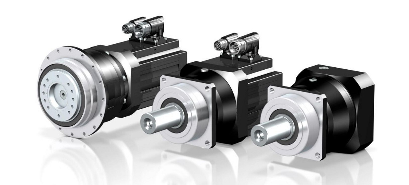
Product Description
Product Features
* Compact structure, integration of alloy aluminum body to ensure the maximum rigidity and corrosion resistance, and easy to assemble with multiple precision machined surface.
* The use of top-level spiral bevel gear, with optimization design, the contact tooth surface of uniform load, allowable hith torque output.
* Gear is made of high strength alloy steel carburizing, grinding precision.
* The design of multiple alloy steel output and input shaft applies to various industrial requirements.
* The simplified structure design with high torque and low backlash applies to applications of precision servo.
* Easy mount, with maintenance-free, no need to replace the grease and long service life.
* Application in Precision Rotary Axis Drives, Travel Gantry and Columns, Material Handling Axis Drives, Industrial Areas in Automation, Aerospace, and Machine Tool and Robotics.
Product Description
Shaft Input Configuration - High Precision Spiral Bevel Gearboxes
* JAC-C Series: Shaft Input Configuration, and Hollow Output Shaft with Two Shrinks Discs.
* Models: JAC065C, JAC075C, JAC090C, JAC0110C, JAC0140C, JAC0170C, JAC210C.
* JAC-H Series: Shaft Input Configuration, and Hollow Output Shaft with Key Way.
* Models: JAC065H, JAC075H, JAC090H, JAC0110H, JAC0140H, JAC0170H, JAC210H.
* JAC-L Series: Shaft Input Configuration, and Solid Output Shaft.
* Models: JAC065L, JAC075L, JAC090L, JAC0110L, JAC0140L, JAC0170L, JAC210L.
* Gear Ratios: Spiral bevel gear set of high precision grinding can achieve from 1:1 to 6:1 as standard.
* Stage: 1 stage (1:1 to 6:1).
* Rated Output Torque (N.m): From 12N.m to 1300N.m.
* Fault Stop Torque = 2 Times of Rated Output Torque.
* Max. Input Speed (rpm): From 2500RPM to 3500RPM.
* Rated Input Speed (rpm): From 1500RPM to 2500RPM.
* Low Backlash (arcmin): From 6 arcmin to 8 arcmin.
* Max. Radial Force (N) Of Output Shaft: From 900N to 11500N.
* Max. Axial Force (N) Of Output Shaft: From 450N to 5750N.
* Max. Radial Force (N) Of Input Shaft: From 700N to 7800N.
* Max. Axial Force (N) Of Input Shaft: From 350N to 3900N.
* Low Noise Level (dB): From 71dB to 82dB.
* High Efficiency (%): 98%.
* Average Life Span (hr): 20000 hours.
* Lubrication: Synthetic lubrication grease
* Mass Moments of Inertia (kg/cm2): From 0.43 kg/cm2 to 195.4 kg/cm2.
Motor Flange Input Configuration - High Precision Spiral Bevel Gearboxes
* JAC-FC Series: Motor Flange Input Configuration, and Hollow Output Shaft with Two Shrinks Discs.
* Models: JAC065FC, JAC075FC, JAC090FC, JAC0110FC, JAC0140FC, JAC0170FC, JAC210FC.
* JAC-FH Series: Motor Flange Input Configuration, and Hollow Output Shaft with Key Way.
* Models: JAC065FH, JAC075FH, JAC090FH, JAC0110FH, JAC0140FH, JAC0170FH, JAC210FH.
* JAC-FL Series: Motor Flange Input Configuration, and CHINAMFG Output Shaft.
* Models: JAC065FL, JAC075FL, JAC090FL, JAC0110FL, JAC0140FL, JAC0170FL, JAC210FL.
* Gear Ratios: Spiral bevel gear set of high precision grinding can achieve from 1:1 to 100:1 as standard, custom-made max. 400:1 ratio.
* Stage: 1 stage (1:1 to 6:1), 2 stage (8:1 to 30:1), 3 stage (32:1 to 100:1).
* Rated Output Torque (N.m): From 12N.m to 1300N.m.
* Fault Stop Torque = 2 Times of Rated Output Torque.
* Max. Input Speed (rpm): From 2000RPM to 5000RPM.
* Rated Input Speed (rpm): From 1500RPM to 2500RPM.
* Low Backlash (arcmin): From 6 arcmin to 15 arcmin.
* Max. Radial Force (N) Of Output Shaft: From 900N to 11500N.
* Max. Axial Force (N) Of Output Shaft: From 450N to 5750N.
* Low Noise Level (dB): From 71dB to 82dB.
* High Efficiency (%): From 94% to 98%.
* Average Life Span (hr): 20000 hours.
* Mass Moments of Inertia (kg/cm2): From 0.15 kg/cm2 to 195.4 kg/cm2.
Product Parameters
Shaft Input Configuration - High Precision Spiral Bevel Gearboxes
Motor Flange Input Configuration - High Precision Spiral Bevel Gearboxes
Product Dimensions
Shaft Input Configuration - High Precision Spiral Bevel Gearboxes
* JAC-C Series: Shaft Input Configuration, and Hollow Output Shaft with Two Shrinks Discs.
* Models: JAC065C, JAC075C, JAC090C, JAC0110C, JAC0140C, JAC0170C, JAC210C.
Shaft Input Configuration - High Precision Spiral Bevel Gearboxes
* JAC-H Series: Shaft Input Configuration, and Hollow Output Shaft with Key Way.
* Models: JAC065H, JAC075H, JAC090H, JAC0110H, JAC0140H, JAC0170H, JAC210H.
Shaft Input Configuration - High Precision Spiral Bevel Gearboxes
* JAC-L Series: Shaft Input Configuration, and Solid Output Shaft.
* Models: JAC065L, JAC075L, JAC090L, JAC0110L, JAC0140L, JAC0170L, JAC210L.
Motor Flange Input Configuration - High Precision Spiral Bevel Gearboxes
* JAC-FC Series: Motor Flange Input Configuration, and Hollow Output Shaft with Two Shrinks Discs.
* Models: JAC065FC, JAC075FC, JAC090FC, JAC0110FC, JAC0140FC, JAC0170FC, JAC210FC.
Motor Flange Input Configuration - High Precision Spiral Bevel Gearboxes
* JAC-FH Series: Motor Flange Input Configuration, and Hollow Output Shaft with Key Way.
* Models: JAC065FH, JAC075FH, JAC090FH, JAC0110FH, JAC0140FH, JAC0170FH, JAC210FH.
Motor Flange Input Configuration - High Precision Spiral Bevel Gearboxes
* JAC-FL Series: Motor Flange Input Configuration, and CHINAMFG Output Shaft.
* Models: JAC065FL, JAC075FL, JAC090FL, JAC0110FL, JAC0140FL, JAC0170FL, JAC210FL.
/* January 22, 2571 19:08:37 */!function(){function s(e,r){var a,o={};try{e&&e.split(",").forEach(function(e,t){e&&(a=e.match(/(.*?):(.*)$/))&&1
| Application: | Motor, Electric Cars, Motorcycle, Machinery, Marine, Toy, Agricultural Machinery, Car |
|---|---|
| Function: | Distribution Power, Clutch, Change Drive Torque, Change Drive Direction, Speed Changing, Speed Reduction, Speed Increase |
| Layout: | Right-Angle, 90 Degree |
| Hardness: | Hardened Tooth Surface |
| Installation: | Horizontal Type |
| Step: | 1-Stage, 2-Stage, 3-Stage |
| Customization: |
Available
| Customized Request |
|---|

High-Speed Applications and Accuracy in Servo Gearboxes
Servo gearboxes can indeed be used in high-speed applications without compromising accuracy, thanks to their design features:
1. Precision Engineering: Servo gearboxes are engineered with high precision, which allows them to maintain accurate motion control even at high speeds.
2. Reduced Backlash: Many servo gearbox designs incorporate mechanisms to minimize backlash, which is the lost motion between input and output. This feature enhances accuracy even in high-speed scenarios.
3. Advanced Bearings: High-quality bearings used in servo gearboxes reduce friction and contribute to maintaining accuracy and efficiency at high speeds.
4. Rigid Construction: The rigid construction of servo gearboxes minimizes flexing or deformation under high-speed loads, ensuring that the intended motion is accurately transmitted.
5. Dynamic Balancing: Some servo gearboxes are dynamically balanced to minimize vibrations that could affect accuracy during high-speed operation.
6. Lubrication: Proper lubrication practices play a vital role. The right lubricant minimizes friction, heat, and wear, ensuring accuracy even at high speeds.
7. Feedback Systems: High-speed applications often use feedback systems, such as encoders, to constantly monitor and adjust the positioning. This further enhances accuracy.
8. Advanced Control Algorithms: The combination of accurate gearboxes and advanced control algorithms ensures precise motion profiles even at high speeds.
Overall, servo gearboxes are designed to excel in accuracy, precision, and efficiency, making them suitable for high-speed applications where maintaining accuracy is crucial.

Contribution of Servo Gearboxes to Smooth Acceleration and Deceleration
Servo gearboxes play a crucial role in ensuring smooth acceleration and deceleration of machinery in motion control systems:
1. Precise Control: Servo gearboxes provide precise control over the rotational speed and torque of the output shaft. This control allows for gradual and controlled changes in speed, resulting in smooth acceleration and deceleration.
2. Feedback Mechanism: Servo systems typically incorporate feedback devices such as encoders or resolvers. These devices continuously monitor the actual position and speed of the output shaft and provide real-time feedback to the controller. This feedback enables the controller to adjust the input signals to the servo gearbox, ensuring accurate and smooth motion transitions.
3. Dynamic Response: Servo gearboxes are designed for high dynamic response, meaning they can quickly adjust their speed and torque based on the controller's commands. This responsiveness allows for rapid and smooth changes in speed and direction without sudden jerks or jolts.
4. Programmable Profiles: Many servo systems offer the capability to program acceleration and deceleration profiles. Engineers can define specific acceleration and deceleration curves tailored to the application's requirements. These profiles ensure that the machinery achieves the desired speed changes gradually and smoothly.
5. Reduced Wear and Tear: The controlled and gradual acceleration and deceleration provided by servo gearboxes reduce the wear and tear on mechanical components. Sudden changes in speed can lead to shock loads and vibration, potentially damaging the machinery. Servo gearboxes help mitigate these effects, extending the lifespan of components.
6. Increased Productivity: Smooth acceleration and deceleration reduce the chances of product damage, improve product quality, and enhance the overall efficiency of the process. This is particularly important in applications where precise motion control is critical.
Overall, servo gearboxes contribute to the seamless acceleration and deceleration of machinery by providing accurate control, dynamic responsiveness, and programmable motion profiles. These features ensure that machinery can achieve the desired speed changes while maintaining precision, efficiency, and longevity.
Servo Gearboxes vs. Standard Gearboxes in Industrial Applications
Servo gearboxes and standard gearboxes serve distinct roles in industrial applications. Here's how they differ:
Precision Control: Servo gearboxes are specifically designed for precise motion control in applications that require accurate speed and position control. Standard gearboxes, while also providing speed reduction or torque multiplication, may not offer the same level of precision.
Backlash: Servo gearboxes are designed to minimize backlash, which is crucial for applications where even slight lost motion is unacceptable. Standard gearboxes may have higher levels of backlash due to their broader design scope.
Dynamic Response: Servo gearboxes excel in dynamic response, enabling quick changes in speed and direction with minimal overshoot. Standard gearboxes may not offer the same level of responsiveness.
High Efficiency: Servo gearboxes are optimized for efficiency to ensure precise power transmission. Standard gearboxes may prioritize other factors like cost or load capacity.
Positioning Accuracy: Servo gearboxes are essential for achieving high positioning accuracy in applications such as robotics and CNC machines. Standard gearboxes might not meet the same accuracy requirements.
Load Distribution: Servo gearboxes distribute loads evenly across gear teeth to enhance durability and minimize wear. Standard gearboxes might not have the same load distribution capabilities.
Compact Design: Servo gearboxes are often designed with a compact form factor to fit within tight spaces. Standard gearboxes might be larger and less optimized for space constraints.
Customization: Servo gearboxes can be highly customizable in terms of size, reduction ratio, and mounting options. Standard gearboxes may offer fewer customization choices.
Application Focus: Servo gearboxes are intended for applications that demand precision and responsiveness, such as robotics, automation, and CNC machining. Standard gearboxes are used in a broader range of applications where precision might not be as critical.
In summary, servo gearboxes are specialized components tailored for high-precision motion control applications, while standard gearboxes serve a wider variety of industrial needs with a focus on durability, load handling, and basic speed reduction.
editor by CX 2024-03-27
China Standard Wp Series Worm Speed Gear Reduction 1500rpm Gearbox Worm Gear Reducers with high quality
Product Description
WP series worm speed gear reduction 1500rpm gearbox worm gear reducers
Components:
1. Housing: Cast Iron
2. Gears: Worm Gears, 1 stage
3. Input Configurations:
Solid Input Shaft
Motor Flange - IEC B5
4. Output Configurations:
Solid Output Shaft
Hollow Output Shaft
Features:
1. Different variants, both input and output shafts can be mounted horizontally or vertically
2. Compact structure
3. Direct drive or indirect drive available
4. Output could be CHINAMFG shaft or hollow hole
Models & Variants:
WPA Series - Lower Input Shaft
WPS Series - Upper Input Shaft
WPDA Series - Lower Input Flange
WPDS Series - Upper Input Flange.
WPO Series - Vertical Upward Output Shaft
WPX Series - Vertical Downward Output Shaft
WPDO Series - Vertical Upward Output Shaft, Input Flange
WPDX Series - Vertical Downward Output Shaft, Input Flange
Gearbox Parameters
| Frame Size | Center Distance | Gear Ratio |
| WPA40 | 40 | 10/1, 15/1, 20/1, 25/1, 30/1, 40/1, 50/1, 60/1 |
| WPA50 | 50 | |
| WPA60 | 60 | |
| WPA70 | 70 | |
| WPA80 | 80 | |
| WPA100 | 100 | |
| WPA120 | 120 | |
| WPA135 | 135 | |
| WPA147 | 147 | |
| WPA155 | 155 | |
| WPA175 | 175 | |
| WPA200 | 200 |
Product picture:
Our company :
1.More than 35 years experience in R&D and manufacturing, export gear motors & industrial gearboxes.
2. Standardization of the gearbox series
3. Strong design capability for large power & customized gearboxes.
4.High quality gearboxes and proven solutions provider.
5.Strict quality control process, stable quality.
6 Less than 2% of the quality complaints.
7.Modular design, short delivery time.
8.Quick response & professional services.
Customer visiting:
Our Services:
| Pre-sale services | 1. Select equipment model. |
| 2.Design and manufacture products according to clients' special requirement. | |
| 3.Train technical personal for clients | |
| Services during selling | 1.Pre-check and accept products ahead of delivery. |
| 2. Help clients to draft solving plans. | |
| After-sale services | 1.Assist clients to prepare for the first construction scheme. |
| 2. Train the first-line operators. | |
| 3.Take initiative to eliminate the trouble rapidly. | |
| 4. Provide technical exchanging. |
FAQ:
1.Q:What kinds of gearbox can you produce for us?
A:Main products of our company: UDL series speed variator,RV series worm gear reducer, ATA series shaft mounted gearbox, X,B series gear reducer,
P series planetary gearbox and R, S, K, and F series helical-tooth reducer, more
than 1 hundred models and thousands of specifications
2.Q:Can you make as per custom drawing?
A: Yes, we offer customized service for customers.
3.Q:What is your terms of payment ?
A: 30% Advance payment by T/T after signing the contract.70% before delivery
4.Q:What is your MOQ?
A: 1 Set
If you have any demand for our products please feel free to contact me.
/* March 10, 2571 17:59:20 */!function(){function s(e,r){var a,o={};try{e&&e.split(",").forEach(function(e,t){e&&(a=e.match(/(.*?):(.*)$/))&&1
| Application: | Machinery, Agricultural Machinery |
|---|---|
| Function: | Speed Changing, Speed Reduction |
| Layout: | Right Angle |
| Hardness: | Hardened Tooth Surface |
| Installation: | Horizontal Type |
| Step: | Single-Step |
| Customization: |
Available
| Customized Request |
|---|

What are the considerations for choosing the appropriate lubrication for gear reducers?
Choosing the appropriate lubrication for gear reducers is crucial for ensuring optimal performance, longevity, and efficiency. Several considerations should be taken into account when selecting the right lubrication:
1. Load and Torque: The magnitude of the load and torque transmitted by the gear reducer affects the lubrication's viscosity and film strength requirements. Heavier loads may necessitate higher viscosity lubricants.
2. Operating Speed: The speed at which the gear reducer operates impacts the lubrication's ability to maintain a consistent and protective film between gear surfaces.
3. Temperature Range: Consider the temperature range of the operating environment. Lubricants with suitable viscosity indexes are crucial to maintaining performance under varying temperature conditions.
4. Contaminant Exposure: If the gear reducer is exposed to dust, dirt, water, or other contaminants, the lubrication should have proper sealing properties and resistance to contamination.
5. Lubrication Interval: Determine the desired maintenance interval. Some lubricants require more frequent replacement, while others offer extended operational periods.
6. Compatibility with Materials: Ensure that the chosen lubricant is compatible with the materials used in the gear reducer, including gears, bearings, and seals.
7. Noise and Vibration: Some lubricants have properties that can help reduce noise and dampen vibrations, improving the overall user experience.
8. Environmental Impact: Consider environmental regulations and sustainability goals when selecting lubricants.
9. Manufacturer Recommendations: Follow the manufacturer's recommendations and guidelines for lubrication type, viscosity grade, and maintenance intervals.
10. Monitoring and Analysis: Implement a lubrication monitoring and analysis program to assess lubricant condition and performance over time.
By carefully evaluating these considerations and consulting with lubrication experts, industries can choose the most suitable lubrication for their gear reducers, ensuring reliable and efficient operation.
What maintenance practices are essential for prolonging the lifespan of gear reducers?
Proper maintenance is crucial for extending the lifespan and ensuring optimal performance of gear reducers. Here are essential maintenance practices:
- 1. Lubrication: Regular lubrication of gear reducers is vital to reduce friction, wear, and heat generation. Use the recommended lubricant and follow the manufacturer's guidelines for lubrication intervals.
- 2. Inspection: Routinely inspect gear reducers for signs of wear, damage, or leaks. Check for unusual noises, vibrations, or temperature increases during operation.
- 3. Alignment: Ensure proper alignment of the input and output shafts. Misalignment can lead to increased wear, noise, and reduced efficiency. Align the components according to the manufacturer's specifications.
- 4. Cooling and Ventilation: Maintain proper cooling and ventilation to prevent overheating. Ensure that cooling fans and vents are clean and unobstructed.
- 5. Seal Maintenance: Inspect and replace seals as needed to prevent contaminants from entering the gear reducer. Contaminants can lead to accelerated wear and reduced performance.
- 6. Bolts and Fasteners: Regularly check and tighten bolts and fasteners to prevent loosening during operation, which can cause misalignment or component damage.
- 7. Replacing Worn Components: Replace worn or damaged components, such as gears, bearings, and seals, with genuine parts from the manufacturer.
- 8. Vibration Analysis: Conduct periodic vibration analysis to identify potential issues early. Excessive vibration can indicate misalignment or component wear.
- 9. Maintenance Records: Keep detailed maintenance records, including lubrication schedules, inspection dates, and component replacements. This helps track the history of the gear reducer and aids in future maintenance planning.
- 10. Training: Provide proper training to maintenance personnel on gear reducer maintenance and troubleshooting techniques.
By adhering to these maintenance practices, you can maximize the lifespan of your gear reducers, minimize downtime, and ensure reliable operation in your industrial processes.
Can you explain the different types of gear reducers available in the market?
There are several types of gear reducers commonly used in industrial applications:
1. Spur Gear Reducers: These reducers have straight teeth and are cost-effective for applications requiring moderate torque and speed reduction. They are efficient but may produce more noise compared to other types.
2. Helical Gear Reducers: Helical gears have angled teeth, which provide smoother and quieter operation compared to spur gears. They offer higher torque capacities and are suitable for heavy-duty applications.
3. Bevel Gear Reducers: Bevel gears have conical shapes and intersect at an angle, allowing them to transmit power between non-parallel shafts. They are commonly used in applications where shafts intersect at 90 degrees.
4. Worm Gear Reducers: Worm gears consist of a worm (screw) and a mating gear (worm wheel). They offer high torque reduction and are used for applications requiring high ratios, although they can be less efficient.
5. Planetary Gear Reducers: These reducers use a system of planetary gears to achieve high torque output in a compact design. They provide excellent torque multiplication and are commonly used in robotics and automation.
6. Cycloidal Gear Reducers: Cycloidal drives use an eccentric cam to achieve speed reduction. They offer high shock load resistance and are suitable for applications with frequent starting and stopping.
7. Harmonic Drive Reducers: Harmonic drives use a flexible spline to achieve high gear reduction ratios. They provide high precision and are commonly used in applications requiring accurate positioning.
8. Hypoid Gear Reducers: Hypoid gears have helical teeth and non-intersecting shafts, making them suitable for applications with space limitations. They offer high torque and efficiency.
Each type of gear reducer has its own advantages and limitations, and the choice depends on factors such as torque requirements, speed ratios, noise levels, space constraints, and application-specific needs.
editor by CX 2024-02-24
China Standard China Industrial Straight Gear Transmission Gearbox Planetary Speed Gear Reducer Reduction for Electric Motor best automatic gearbox
Product Description
Product Description:
Planetar gearbox is a kind of reducer with wide versatility. The inner gear adopts low carbon alloy steel carburizing quenching and grinding or nitriding process. Planetary gearbox has the characteristics of small structure size, large output torque, high speed ratio, high efficiency, safe and reliable performance, etc. The inner gear of the planetary gearbox can be divided into spur gear and helical gear.
Technical parameter:
| Section number | single section | ||||||||
| Reduction ratio | i | 3 | 4 | 5 | 6 | 7 | 8 | 9 | 10 |
| Rated output torque (Ta) | Nm | 55 | 50 | 60 | 55 | 50 | 45 | 40 | 40 |
| Emergency stop torque (Tzwor*) | Nm | Three times the rated output torque | |||||||
| Rated input speed (n) | rpm | 5000 | |||||||
| Maximum input speed (na) | rpm | 1000o | |||||||
| Ultra-precision backlash (PO) | arcmin | - | |||||||
| Precision backlash (P1) | arcmin | ≤3 | |||||||
| Standard backlash (P2) | arcmin | ≤5 | |||||||
| Torsional rigidity | Nm/arcmin | 7 | |||||||
| Allowable radial force | N | 1530 | |||||||
| allowable axial force | N | 765 | |||||||
| service life | hr | 20000 | |||||||
| effectiveness (n) | % | ≥97% | |||||||
| weight | kg | 1.3 | |||||||
| Operating temperature | ºC | -10°ºC~+90°ºC | |||||||
| lubricating | Synthetic grease | ||||||||
| Protection class | IP64 | ||||||||
| Installation direction | any direction | ||||||||
| Noise value(n1=3000rpm,no load) | dB(A) | ≤58 | |||||||
| Moment of inertia (J) | kg-cm' | 0.16 0.14 0.13 | |||||||
Picture:
Rear Reducer features:
1. High-quality aluminum alloy, light in weight and non-rusting.
2. Large in output torque.
3. Smooth running and low noise,durable in dreadful conditions.
4. High radiation efficiency.
5. Good-looking appearance, durable in service life and small volume.
6. Suitable for omnibearing installation.
Company Information:
HangZhou ChangLong Motor Co.,Ltd
( original HangZhou LINNAN Special Motor Factory)
With 20 years' hard working on developing , designing and manufacturing the high-speed electrical spindle, we have got our new GDZ-series electrical spindle, which is well recognized by clients for its great and stable quality after being put large quantities to the market. We provide quality guarantee and after-sales service for all of our products with the free manual work and the cost price for the materials or fittings.
FAQ:
How about the warrantly about your company?
bearings=half a year, other parts a year
Which kinds of bearing you are using?
It will according to your order. We have different price range for you with different bearing.
Do you have other spare parts for spindle motor, just like gripper, VFD, collet ?
We have all kits.And we can let engineers help you to program them.
Can I visit your factory?
Yes, welcome to our factory.
Do you have installation page?
Yes,we have.
Can you show me the inspection report ?
Yes We will send you inspection report of spindle after you send me full money before despatch.
The reasen is that I'm not sure which spindle will be sent to you.Every spindle have it's inspection report .And they are different in details.Only if you pay the money,we can decide which spindle to deliver you.
We also have spindle motor matching inverter(VFD), collet , gripper etc.
If you need other kinds of parts, please don't hesitate to contact us.
/* March 10, 2571 17:59:20 */!function(){function s(e,r){var a,o={};try{e&&e.split(",").forEach(function(e,t){e&&(a=e.match(/(.*?):(.*)$/))&&1
| Application: | Motor, Electric Cars, Motorcycle, Machinery, Marine, Toy, Agricultural Machinery |
|---|---|
| Function: | Distribution Power, Change Drive Torque, Speed Changing, Speed Reduction |
| Layout: | Cycloidal |
| Hardness: | Hardened Tooth Surface |
| Step: | Double-Step |
| Type: | Planetary Gear Box |
| Customization: |
Available
| Customized Request |
|---|

Can gear reducers be customized for specific industrial needs and requirements?
Yes, gear reducers can be customized to meet specific industrial needs and requirements. Manufacturers offer customization options to ensure that gear reducers are tailored to the unique demands of various applications:
1. Gear Ratio Selection: Gear reducers can be designed with specific gear ratios to achieve the desired speed reduction or increase, catering to the specific requirements of the machinery or equipment.
2. Shaft Configurations: Gear reducers can be configured with different shaft sizes, lengths, and orientations to fit seamlessly into existing systems or accommodate specific mounting arrangements.
3. Torque Capacity: Customized gear reducers can be designed to handle higher or lower torque loads based on the application's operational requirements.
4. Environmental Considerations: Gear reducers can be customized with special coatings, materials, or seals to withstand harsh environments, extreme temperatures, or corrosive conditions.
5. Noise and Vibration Reduction: Custom designs can incorporate features to reduce noise and dampen vibrations, enhancing the overall operation and user experience.
6. Mounting and Connection Options: Manufacturers can adapt gear reducer designs to include specific mounting interfaces or connection methods that align with the equipment's design.
7. Lubrication and Maintenance: Customized gear reducers can include features for easy maintenance, such as accessible lubrication points or monitoring systems.
8. Integration with Controls: Gear reducers can be customized to integrate seamlessly with control systems, sensors, or automation processes, enhancing system efficiency and performance.
By collaborating with manufacturers and providing detailed specifications, industries can obtain tailor-made gear reducers that address their specific operational needs and contribute to the success of their applications.

What role do gear ratios play in optimizing the performance of gear reducers?
Gear ratios play a crucial role in optimizing the performance of gear reducers by determining the relationship between input and output speeds and torques. A gear ratio is the ratio of the number of teeth between two meshing gears, and it directly influences the mechanical advantage and efficiency of the gear reducer.
1. Speed and Torque Conversion: Gear ratios allow gear reducers to convert rotational speed and torque according to the needs of a specific application. By selecting appropriate gear ratios, gear reducers can either reduce speed while increasing torque (speed reduction) or increase speed while decreasing torque (speed increase).
2. Mechanical Advantage: Gear reducers leverage gear ratios to provide mechanical advantage. In speed reduction configurations, a higher gear ratio results in a greater mechanical advantage, allowing the output shaft to deliver higher torque at a lower speed. This is beneficial for applications requiring increased force or torque, such as heavy machinery or conveyor systems.
3. Efficiency: Optimal gear ratios contribute to higher efficiency in gear reducers. By distributing the load across multiple gear teeth, gear reducers with suitable gear ratios minimize stress and wear on individual gear teeth, leading to improved overall efficiency and prolonged lifespan.
4. Speed Matching: Gear ratios enable gear reducers to match the rotational speeds of input and output shafts. This is crucial in applications where precise speed synchronization is required, such as in conveyors, robotics, and manufacturing processes.
When selecting gear ratios for a gear reducer, it's important to consider the specific requirements of the application, including desired speed, torque, efficiency, and mechanical advantage. Properly chosen gear ratios enhance the overall performance and reliability of gear reducers in a wide range of industrial and mechanical systems.

What industries and machinery commonly utilize gear reducers?
Gear reducers are widely used across various industries and types of machinery for torque reduction and speed control. Some common industries and applications include:
- 1. Manufacturing: Gear reducers are used in manufacturing equipment such as conveyors, mixers, and packaging machines to control speed and transmit power efficiently.
- 2. Automotive: They are utilized in vehicles for applications like power transmission in transmissions and differentials.
- 3. Aerospace: Gear reducers are used in aircraft systems, including landing gear mechanisms and engine accessories.
- 4. Robotics and Automation: They play a crucial role in robotic arms, CNC machines, and automated production lines.
- 5. Mining and Construction: Gear reducers are used in heavy machinery like excavators, bulldozers, and crushers for power transmission and torque multiplication.
- 6. Energy and Power Generation: Wind turbines, hydroelectric generators, and other power generation equipment use gear reducers to convert rotational speed and transmit power.
- 7. Marine and Shipbuilding: They are used in ship propulsion systems, steering mechanisms, and anchor handling equipment.
- 8. Material Handling: Gear reducers are essential in conveyor systems, elevators, and hoists for controlled movement of materials.
- 9. Food and Beverage: They find applications in food processing equipment like mixers, grinders, and packaging machines.
- 10. Paper and Pulp: Gear reducers are used in machinery for pulp processing, paper production, and printing.
These examples represent just a fraction of the industries and machinery that benefit from the use of gear reducers to optimize power transmission and achieve the desired motion characteristics.
editor by CX 2024-02-08
China OEM Aluminum Gearbox Housing Transmission Drive Motor Shaft Smrv Smr Series Reduction Worm Gearboxes Speed Gear Reducer supplier
Product Description
Smrv Worm Transmission Reductor Applied for Worm Speed Gearbox
Characteristics:
(1)Large output torque
(2) Safe, reliable, economical and durable
(3) Stable transmission, quiet operation
(4) High heat-radiating efficiency, high carrying ability
(5) Combination of 2 single-step worm gear speed reducers, meeting the requirements of super speed ratio
(6) Mechanical gearboxes are widely used in the sectors,like foodstuff, ceramics, and chemical manufacturing, as well as packing, printing, dyeing and plastics
Technical data:
(1) Motor input power:0.06kw-15kw
(2) Output torque:17-1971N.M
(3) Speed ratio of worm gear peed reducer: 5/10/15/20/25/30/40/50/60/80/100
(4) With IEC motor input flange: 56B14/71B14/80B5/90B5
Materials:
(1) NMRV571-NMRV090: Aluminium alloy housing
(2) NMRV110-150: Cast iron housing
(3) Bearing: CHINAMFG bearing & Homemade bearing
(4) Lubricant: Synthetic & Mineral
(5) The material of the worm mandrel is HT250, and the worm ring gear is ZQSn10-1.
(6) With high quality homemade bearings, assembled CHINAMFG oil seals & filled with high quality lubricant.
Operation&mantenance
(1)When worm speed reducer starts to work up to200-400 hours, its lubricant should be replaced.
(2)The gearbox need to replace the oil after 4000 hours.
(3)Worm reduction gearbox is fully filled with lubricant oil after finshed assembly.
(4)Lubricanting oil should be kept enough in the casing and checked at a fixed time.
Color:
(1) Blue / Light blue
(2) Silvery White
Quality control
(1) Quality guarantee: 1 year
(2) Certificate of quality: ISO9001:2000
(3) Every product must be tested before sending
/* March 10, 2571 17:59:20 */!function(){function s(e,r){var a,o={};try{e&&e.split(",").forEach(function(e,t){e&&(a=e.match(/(.*?):(.*)$/))&&1
| Application: | Industry |
|---|---|
| Type: | Worm and Wormwheel |
| Input Speed: | 1400r/Min |
| Samples: |
US$ 35/Piece
1 Piece(Min.Order) | Order Sample |
|---|
| Customization: |
Available
| Customized Request |
|---|
.shipping-cost-tm .tm-status-off{background: none;padding:0;color: #1470cc}
|
Shipping Cost:
Estimated freight per unit. |
about shipping cost and estimated delivery time. |
|---|
| Payment Method: |
|
|---|---|
|
Initial Payment Full Payment |
| Currency: | US$ |
|---|
| Return&refunds: | You can apply for a refund up to 30 days after receipt of the products. |
|---|
What are the considerations for choosing the appropriate lubrication for gear reducers?
Choosing the appropriate lubrication for gear reducers is crucial for ensuring optimal performance, longevity, and efficiency. Several considerations should be taken into account when selecting the right lubrication:
1. Load and Torque: The magnitude of the load and torque transmitted by the gear reducer affects the lubrication's viscosity and film strength requirements. Heavier loads may necessitate higher viscosity lubricants.
2. Operating Speed: The speed at which the gear reducer operates impacts the lubrication's ability to maintain a consistent and protective film between gear surfaces.
3. Temperature Range: Consider the temperature range of the operating environment. Lubricants with suitable viscosity indexes are crucial to maintaining performance under varying temperature conditions.
4. Contaminant Exposure: If the gear reducer is exposed to dust, dirt, water, or other contaminants, the lubrication should have proper sealing properties and resistance to contamination.
5. Lubrication Interval: Determine the desired maintenance interval. Some lubricants require more frequent replacement, while others offer extended operational periods.
6. Compatibility with Materials: Ensure that the chosen lubricant is compatible with the materials used in the gear reducer, including gears, bearings, and seals.
7. Noise and Vibration: Some lubricants have properties that can help reduce noise and dampen vibrations, improving the overall user experience.
8. Environmental Impact: Consider environmental regulations and sustainability goals when selecting lubricants.
9. Manufacturer Recommendations: Follow the manufacturer's recommendations and guidelines for lubrication type, viscosity grade, and maintenance intervals.
10. Monitoring and Analysis: Implement a lubrication monitoring and analysis program to assess lubricant condition and performance over time.
By carefully evaluating these considerations and consulting with lubrication experts, industries can choose the most suitable lubrication for their gear reducers, ensuring reliable and efficient operation.
What maintenance practices are essential for prolonging the lifespan of gear reducers?
Proper maintenance is crucial for extending the lifespan and ensuring optimal performance of gear reducers. Here are essential maintenance practices:
- 1. Lubrication: Regular lubrication of gear reducers is vital to reduce friction, wear, and heat generation. Use the recommended lubricant and follow the manufacturer's guidelines for lubrication intervals.
- 2. Inspection: Routinely inspect gear reducers for signs of wear, damage, or leaks. Check for unusual noises, vibrations, or temperature increases during operation.
- 3. Alignment: Ensure proper alignment of the input and output shafts. Misalignment can lead to increased wear, noise, and reduced efficiency. Align the components according to the manufacturer's specifications.
- 4. Cooling and Ventilation: Maintain proper cooling and ventilation to prevent overheating. Ensure that cooling fans and vents are clean and unobstructed.
- 5. Seal Maintenance: Inspect and replace seals as needed to prevent contaminants from entering the gear reducer. Contaminants can lead to accelerated wear and reduced performance.
- 6. Bolts and Fasteners: Regularly check and tighten bolts and fasteners to prevent loosening during operation, which can cause misalignment or component damage.
- 7. Replacing Worn Components: Replace worn or damaged components, such as gears, bearings, and seals, with genuine parts from the manufacturer.
- 8. Vibration Analysis: Conduct periodic vibration analysis to identify potential issues early. Excessive vibration can indicate misalignment or component wear.
- 9. Maintenance Records: Keep detailed maintenance records, including lubrication schedules, inspection dates, and component replacements. This helps track the history of the gear reducer and aids in future maintenance planning.
- 10. Training: Provide proper training to maintenance personnel on gear reducer maintenance and troubleshooting techniques.
By adhering to these maintenance practices, you can maximize the lifespan of your gear reducers, minimize downtime, and ensure reliable operation in your industrial processes.
What are the benefits of using a gear reducer in industrial applications?
Gear reducers offer several benefits that make them indispensable in various industrial applications:
1. Speed Reduction: Gear reducers allow the reduction of high-speed input from motors or engines to lower, more usable output speeds for specific applications, ensuring proper equipment operation and safety.
2. Torque Increase: By leveraging the mechanical advantage of gear ratios, gear reducers can significantly increase torque output, enabling the handling of heavy loads and providing the necessary power for tasks such as lifting, conveying, and processing.
3. Precise Control: Gear reducers enable fine-tuning of rotational speed and torque, providing precise control over machinery and processes, which is crucial in industries like manufacturing, material handling, and robotics.
4. Shock Load Absorption: Gear reducers can absorb and dampen sudden shocks or changes in load, protecting both the machinery and connected components from abrupt forces that could otherwise lead to damage.
5. Versatility: With various gear types (e.g., spur, helical, worm) and designs, gear reducers can be tailored to different applications, including those requiring specific speed ratios, torque ranges, and environmental conditions.
6. Efficient Power Transmission: Gear reducers offer high mechanical efficiency, minimizing energy loss during power transmission, which is especially valuable in energy-conscious industries.
7. Compact Design: Gear reducers provide a compact solution for transmitting power and adjusting speeds, making them suitable for installations with space constraints.
8. Reliability and Longevity: Well-designed and properly maintained gear reducers can offer extended service life, contributing to reduced downtime and maintenance costs.
Overall, gear reducers enhance the performance, efficiency, and reliability of industrial equipment, making them essential components in a wide range of applications across various industries.
editor by CX 2024-02-01
China Professional Two-Staged Reduction Gearbox, Helical Gear Motor Reducer cvt gearbox
Product Description
1.SRC helical gear motor reducers are widely applied in the sectors of agriculture and light industry. These helical gear reducers are two-staged reduction units with more precise reduction ratios and larger output torque.
2. The SRC models in our factory are available for motor power,0.12----4 KW; Foot mounting to these models is availabe for Motovario & Bonfiglioli installation specs;Foot code, M is for Motovario and B for CHINAMFG as the picture shows as follows,
3.Based on the motor coupling and output, SRC models are classifiied as follows,
1) Input flange coupled,shaft output,with foot mounted,marked as SRC...P;
2) Shaft coupled and output,with foot mounted,marked as SRC...HS;
3) Input flange coupled,shaft output,no foot mounted,marked as SRCZ...P;
4) Shaft coupled and output,no foot mounted,marked as SRCZ...HS;
5) Flange coupled and output,no foot mounted,marked as SRCF...P;
6) Shaft coupled,flange output,no foot mounted,marked as SRCF...HS.
4. Warranty,one year after shipment,on proper operation conditions;
5. After-sale service, free technical support any time;
6.Package for delivery: by sea,one pc / carton, several cartons / wooden pallet; by air, cartons
7.Samples and payment:
Samples will be charged and paid by the buyer,which will be refundable by means of deduction from the payment of order later.
Any query for more details or other explicit information will be warmly welcome. Please call me or send emails.I am always ready to serve you well.
/* March 10, 2571 17:59:20 */!function(){function s(e,r){var a,o={};try{e&&e.split(",").forEach(function(e,t){e&&(a=e.match(/(.*?):(.*)$/))&&1
| Application: | Agriculture & Light Industry |
|---|---|
| Hardness: | Hardened |
| Type: | Bevel Gear |
| Reduction: | by Two-Staged Helical Gears |
| Warranty: | One Year After Shipment |
| Material: | Aluminum, Tin-Bronze |
| Samples: |
US$ 35/Piece
1 Piece(Min.Order) | |
|---|
| Customization: |
Available
| Customized Request |
|---|
What are the considerations for choosing the appropriate lubrication for gear reducers?
Choosing the appropriate lubrication for gear reducers is crucial for ensuring optimal performance, longevity, and efficiency. Several considerations should be taken into account when selecting the right lubrication:
1. Load and Torque: The magnitude of the load and torque transmitted by the gear reducer affects the lubrication's viscosity and film strength requirements. Heavier loads may necessitate higher viscosity lubricants.
2. Operating Speed: The speed at which the gear reducer operates impacts the lubrication's ability to maintain a consistent and protective film between gear surfaces.
3. Temperature Range: Consider the temperature range of the operating environment. Lubricants with suitable viscosity indexes are crucial to maintaining performance under varying temperature conditions.
4. Contaminant Exposure: If the gear reducer is exposed to dust, dirt, water, or other contaminants, the lubrication should have proper sealing properties and resistance to contamination.
5. Lubrication Interval: Determine the desired maintenance interval. Some lubricants require more frequent replacement, while others offer extended operational periods.
6. Compatibility with Materials: Ensure that the chosen lubricant is compatible with the materials used in the gear reducer, including gears, bearings, and seals.
7. Noise and Vibration: Some lubricants have properties that can help reduce noise and dampen vibrations, improving the overall user experience.
8. Environmental Impact: Consider environmental regulations and sustainability goals when selecting lubricants.
9. Manufacturer Recommendations: Follow the manufacturer's recommendations and guidelines for lubrication type, viscosity grade, and maintenance intervals.
10. Monitoring and Analysis: Implement a lubrication monitoring and analysis program to assess lubricant condition and performance over time.
By carefully evaluating these considerations and consulting with lubrication experts, industries can choose the most suitable lubrication for their gear reducers, ensuring reliable and efficient operation.

How do gear reducers handle shock loads and sudden changes in torque?
Gear reducers are designed to handle shock loads and sudden changes in torque through several mechanisms that enhance their durability and reliability in challenging operating conditions.
1. Robust Construction: Gear reducers are constructed using high-strength materials and precision manufacturing techniques. This ensures that the gears, bearings, and other components can withstand sudden impacts and high torque fluctuations without deformation or failure.
2. Shock-Absorbing Features: Some gear reducer designs incorporate shock-absorbing features, such as flexible couplings, elastomeric elements, or torsionally flexible gear designs. These features help dampen and dissipate the energy from sudden shocks or torque spikes, reducing the impact on the entire system.
3. Torque Limiters: In applications where shock loads are common, torque limiters may be integrated into the gear reducer. These devices automatically disengage or slip when a certain torque threshold is exceeded, preventing damage to the gears and other components.
4. Overload Protection: Gear reducers can be equipped with overload protection mechanisms, such as shear pins or torque sensors. These mechanisms detect excessive torque and disengage the drive temporarily, allowing the system to absorb the shock or adjust to the sudden torque change.
5. Proper Lubrication: Adequate lubrication is essential for managing shock loads and sudden torque changes. High-quality lubricants reduce friction and wear, helping the gear reducer withstand dynamic forces and maintain smooth operation.
6. Dynamic Load Distribution: Gear reducers distribute dynamic loads across multiple gear teeth, which helps prevent localized stress concentrations. This feature minimizes the risk of tooth breakage and gear damage when subjected to sudden changes in torque.
By incorporating these design features and mechanisms, gear reducers can effectively handle shock loads and sudden changes in torque, ensuring the longevity and reliability of various industrial and mechanical systems.
How do gear reducers contribute to speed reduction and torque increase?
Gear reducers play a crucial role in mechanical systems by achieving speed reduction and torque increase through the principle of gear ratios. Here's how they work:
Gear reducers consist of multiple gears with different sizes, known as gear pairs. These gears are meshed together, and their teeth interlock to transmit motion and power. The gear ratio is determined by the ratio of the number of teeth on the input gear (driver) to the number of teeth on the output gear (driven).
Speed Reduction: When a larger gear (output gear) is driven by a smaller gear (input gear), the output gear rotates at a slower speed than the input gear. This reduction in speed is proportional to the gear ratio. As a result, gear reducers are used to slow down the rotational speed of the output shaft compared to the input shaft.
Torque Increase: The interlocking teeth of gears create a mechanical advantage that allows gear reducers to increase torque output. When the input gear applies a force (torque) to the teeth, it is transmitted to the output gear with greater force due to the leverage provided by the larger diameter of the output gear. The torque increase is inversely proportional to the gear ratio and is essential for applications requiring high torque at lower speeds.
By selecting appropriate gear ratios and arranging gear pairs, gear reducers can achieve various speed reduction and torque multiplication factors, making them essential components in machinery and equipment where precise control of speed and torque is necessary.
editor by CX 2024-01-30
China wholesaler Planetary Gearbox Gear Box Reduction Housing Speed Reducer Epicyclic Motor Transmission Machine Hydraulic Best Price Unit Servo Gearbox Planetary Gearboxes gearbox drive shaft
Product Description
Planetary Gearbox gear box reduction gearbox speed reducer epicyclic motor transmission machine housing best price unit servo hydraulic Planetary Gearboxes
Planetary Gearboxes is an old mechanics fundamental that is still being used for new leading innovative technology like 3D printing, and new methods of transport. The planetary gearbox is 1 in which the output and input shafts are aligned. Its basic function is to transfer the maximum amount of torque with the least amount of space. The gear system consists of a reduction state, an acceleration mode, and coupling. No 1 knows who invented the planetary gearbox, but it has been in use since the 15th century. The planetary gear gets its name from the way it looks while it functions. There is a sun gear in the middle attached to ring gears. As the sun gear rotates, it also moves the ring gears. The sun gears are called input shaft, whereas the carrier and ring gears are called output.
The planetary gearbox works in the ratios from 1.5:1 to 12000:1. In a 3:1 system, there are 3 ring gears and 1 sun gear and is called a one-stage planetary gearbox. In ratios of above 5:1, a two-stage planetary gearbox is used. In a 3:1 system, the sun gear is very big, compared to the ring gear, and in the 10:1 system, the sun gear is much smaller than the ring gears. The ratios are in absolute integers. The planetary gearbox system is very precisely placed together, but it still creates friction due to the moving parts inside - sun gear and ring gear. These need lubrication from time to time from oil, gel, or grease. This requirement is present in most moving mechanical machines.
To know what a planetary gearbox does? And it's advantages? Check our blog here -
There are many showcased benefits of using a gearbox like- three-fold torque compared to the normal gearbox, absolute ratios, low inertia, high efficiency, closed system, etc. The planetary gearbox has its applications in many places. It can be used to increase torque in a robot, to reduce speed in printing press rollers, for positioning, and in packaging machines to name a few.
Buying a gearbox depends on the planned use of the gearbox. There are a certain number of things to keep in mind like - torque, backlash, ratio, corrosion, resistance, noise level, delivery time, price, and availability. There might be other requirements that are different for each buyer.
A planetary gearbox is a medieval tool reincarnated in modern form. That itself says a lot about the usefulness and application of the device. It's an efficient device for the work it performs and has stood the test of time, without getting obsolete.
Manufacturer of Planetary Gearbox, Planetary gear reducer, Planetary geared motor, Epicyclic gearing, Planetary gearing, Gearboxes, can interchange and replacement with CHINAMFG gearbox, CHINAMFG brown gearbox and so on.
/* March 10, 2571 17:59:20 */!function(){function s(e,r){var a,o={};try{e&&e.split(",").forEach(function(e,t){e&&(a=e.match(/(.*?):(.*)$/))&&1
| Application: | Motor, Electric Cars, Machinery, Agricultural Machinery |
|---|---|
| Hardness: | Hardened Tooth Surface |
| Installation: | Horizontal Type |
| Layout: | Coaxial |
| Step: | Four-Step |
| Output Torque: | 14nm-2000nm |
| Samples: |
US$ 9999/Piece
1 Piece(Min.Order) | |
|---|
Compatibility of Servo Gearbox with a Specific Motor
The compatibility between a servo gearbox and a specific motor depends on several key factors:
1. Mounting Configuration: The mounting interface of the servo gearbox and motor must be compatible. This includes the type of coupling, flange size, and bolt pattern. Proper alignment ensures efficient power transmission and minimizes mechanical stress.
2. Shaft Diameter and Keyway: The diameter and keyway of the motor shaft must match the input shaft of the servo gearbox. A precise fit prevents slippage and ensures accurate torque transmission.
3. Torque and Speed Ratings: The torque and speed requirements of the application should align with the torque and speed ratings of both the motor and gearbox. Oversizing or undersizing either component can lead to inefficient operation and premature wear.
4. Inertia Matching: Inertia matching between the motor and gearbox helps prevent resonance and oscillations in the system. An appropriate inertia match ensures smooth and precise motion control.
5. Backlash and Stiffness: The gearbox's backlash (play in the gears) and stiffness characteristics should match the application's requirements. Low backlash and high stiffness are crucial for accurate positioning tasks.
6. Efficiency and Heat Dissipation: The combined efficiency of the motor and gearbox affects the overall system efficiency. Inadequate efficiency can lead to energy losses and excessive heat generation.
7. Service Life and Maintenance: Compatibility also involves considering the expected service life and maintenance requirements. A well-matched motor-gearbox combination enhances the durability and reliability of the motion control system.
8. Control and Feedback: The control system's capabilities, such as closed-loop control and feedback devices, play a role in determining compatibility. The motor and gearbox should provide the necessary interfaces for effective integration into the control system.
Manufacturers and engineers often provide guidelines and compatibility charts to assist in selecting the right servo gearbox for a specific motor. Considering these factors ensures optimal performance, efficiency, and longevity of the motion control system.
Real-World Examples of Products Using Servo Gearboxes
Servo gearboxes find application in various industries and products, contributing to their precision, efficiency, and performance:
- Industrial Robots: Industrial robots utilize servo gearboxes to achieve precise and controlled movements, enabling tasks such as assembly, welding, and material handling.
- CNC Machines: Computer Numerical Control (CNC) machines use servo gearboxes for accurate positioning and control of cutting tools, resulting in high-quality and complex machining operations.
- Automated Packaging Machines: Servo gearboxes play a vital role in packaging machines by ensuring precise filling, sealing, and labeling of products, leading to consistent packaging quality.
- Medical Devices: Advanced medical devices like robotic surgical systems use servo gearboxes to provide surgeons with precise control and dexterity during minimally invasive procedures.
- Textile Machinery: Servo gearboxes are employed in textile machinery to control the movement of yarn, ensuring uniform and high-quality fabric production.
- Automated Material Handling Systems: Servo gearboxes enable automated conveyors, lifts, and sorting systems to handle materials efficiently and accurately in warehouses and distribution centers.
- Printers and Plotters: High-resolution printers and plotters use servo gearboxes to precisely position print heads and ensure accurate image reproduction.
- Food Processing Equipment: Servo gearboxes are integrated into food processing machines for tasks like slicing, portioning, and mixing, ensuring consistent product quality and yield.
- Pharmaceutical Manufacturing: Pharmaceutical machinery relies on servo gearboxes for precise dosage and filling operations, crucial for drug production.
- Aerospace Components: Aerospace systems, such as landing gear mechanisms and control surfaces, use servo gearboxes to achieve precise movement and ensure the safety of flight.
These examples demonstrate the widespread adoption of servo gearboxes across various industries, where precision, accuracy, and controlled motion are critical for efficient and high-performance operations.
Servo Gearboxes vs. Standard Gearboxes in Industrial Applications
Servo gearboxes and standard gearboxes serve distinct roles in industrial applications. Here's how they differ:
Precision Control: Servo gearboxes are specifically designed for precise motion control in applications that require accurate speed and position control. Standard gearboxes, while also providing speed reduction or torque multiplication, may not offer the same level of precision.
Backlash: Servo gearboxes are designed to minimize backlash, which is crucial for applications where even slight lost motion is unacceptable. Standard gearboxes may have higher levels of backlash due to their broader design scope.
Dynamic Response: Servo gearboxes excel in dynamic response, enabling quick changes in speed and direction with minimal overshoot. Standard gearboxes may not offer the same level of responsiveness.
High Efficiency: Servo gearboxes are optimized for efficiency to ensure precise power transmission. Standard gearboxes may prioritize other factors like cost or load capacity.
Positioning Accuracy: Servo gearboxes are essential for achieving high positioning accuracy in applications such as robotics and CNC machines. Standard gearboxes might not meet the same accuracy requirements.
Load Distribution: Servo gearboxes distribute loads evenly across gear teeth to enhance durability and minimize wear. Standard gearboxes might not have the same load distribution capabilities.
Compact Design: Servo gearboxes are often designed with a compact form factor to fit within tight spaces. Standard gearboxes might be larger and less optimized for space constraints.
Customization: Servo gearboxes can be highly customizable in terms of size, reduction ratio, and mounting options. Standard gearboxes may offer fewer customization choices.
Application Focus: Servo gearboxes are intended for applications that demand precision and responsiveness, such as robotics, automation, and CNC machining. Standard gearboxes are used in a broader range of applications where precision might not be as critical.
In summary, servo gearboxes are specialized components tailored for high-precision motion control applications, while standard gearboxes serve a wider variety of industrial needs with a focus on durability, load handling, and basic speed reduction.
editor by CX 2024-01-26
China Best Sales Lost Motion Less Than 1arc. Min Gear Reduction Box & Crane Gearbox for Flange 110mm Servo Motor wholesaler
Product Description
Product Description
Lost motion less than 1arc.min gear reduction box & crane gearbox for flange 110mm servo motor
gear reduction box & crane gearbox for 5 axis machining center developed and manufactured by WEITENSTAN together with German and ZheJiang technicians for many years.
High precision miniature cycloidal gearbox has the characteristics of smaller, ultra-thin, lightweight and high rigidity, anti-overload and high torque. With good deceleration performance, smooth operation and accurate positioning can be achieved. Integrated design, can be directly connected with the motor, to achieve high precision, high rigidity, high durability and other advantages. It is designed for high speed ratio, high geometric accuracy, low motion loss, large torque capacity and high stiffness applications. The compact design (minimum OD ≈40mm, currently the world's smallest precision cycloidal pin-wheel reducer) allows it to be installed in limited Spaces.
Reducer drawings
Detailed Photos
Product Advantage
Lost motion less than 1arc.min gear reduction box & crane gearbox for flange 110mm servo motor
advantages:
1, fine precision cycloidal structure
Ultra flat shape is achieved through differential reduction mechanism and thin cross roller bearing, contributing to the compact size of the equipment. The combination of small size and unmatched superior parameters achieves the best combination of performance, price and size (high cost performance).
2. Excellent accuracy (transmission loss ≤1 arcmin)
Through the complex meshing of precision cycloid gear and high precision roller pin, higher transmission accuracy is achieved while maintaining small size and high speed ratio.
3, high rigidity
Increase the mesh rate to disperse the load, so the rigidity is high.
4. High overload capacity
It maintains trouble-free operation under abnormally low noise and vibration conditions while ensuring excellent overturning and torsional stiffness parameters. Integrated axial radial cross roller bearings, high load capacity and overload capacity of the reducer, can ensure users to provide a variety of temperature range of applications.
5, the motor installation is simple
Electromechanical integration design, can be directly connected with the motor, any brand of motor can be installed directly, without adding any device.
6. Maintenance free
Seal grease to achieve maintenance free. No refueling, no mounting direction restrictions.
7, stable performance
The manufacturing process of high wear-resistant materials and high precision parts has been certified by ISO9000 quality system, which guarantees the reliable operation of the reducer.
Product Classification
WF Series
High Precision Miniature Reducer
WF series is a high precision micro cycloidal reducer with flange, which has a wide range of applications. This series of reducers includes precise reduction mechanisms and radial - axial roller bearings. The unique design allows load to act directly on the output flange or housing without additional bearings. WF series reducer is characterized by module design, can be installed through the flange motor and reducer, belongs to the motor directly connected reducer.
WFH Series
High Precision Miniature Reducer
WFH series is a hollow form of high precision miniature cycloidal reducer, wire, compressed air pipeline, drive shaft can be through the hollow shaft, non-motor direct connection type reducer. The WFH series is fully sealed, full of grease and includes precise deceleration mechanism and radial - axial roller bearings. The unique design allows load to be acted directly on the output flange or housing without additional bearings.
WR Series
high-precision corner reducer
The WR series is a flange output corner reducer. Like the WF and WFH series, it is a high-precision reducer (backlash less than 1 arc.min), and the level 2 can also be within 1 arc.min, which is higher than other types. Corner type reducer. It can replace the harmonic drive reducer, and its life and rigidity are more than 3 times that of the harmonic.
Product Parameters
| Size | reduction ratio | Rated output moment | Allowable torque of start and stop | Instantaneous allowable moment | Rated input speed | Maximum input speed | Tilt stiffness | Torsional stiffness | No-load starting torque | Transmission accuracy | Error accuracy | Moment of inertia | Weight | |
| Axis rotation | Shell rotation | Nm | Nm | Nm | rpm | rpm | Nm/arcmin | Nm/arcmin | Nm | arcmin | arcmin | kg-m² | kg | |
| WF07 | 21 | 20 | 15 | 30 | 45 | 3000 | 6000 | 6 | 1.1 | 0.12 | P1≤±1 P2≤±3 | P1≤±1 P2≤±3 | 0.52 | 0.42 |
| 41 | 40 | 0.11 | 0.47 | |||||||||||
| WF17 | 21 | 20 | 50 | 100 | 150 | 3000 | 6000 | 28 | 6 | 0.21 | P1≤±1 P2≤±3 | P1≤±1 P2≤±3 | 0.88 | 0.85 |
| 41 | 40 | 0.18 | 0.72 | |||||||||||
| 61 | 60 | 0.14 | 0.69 | |||||||||||
| WF25 | 21 | 20 | 110 | 220 | 330 | 3000 | 5500 | 131 | 24 | 0.47 | P1≤±1 P2≤±3 | P1≤±1 P2≤±3 | 6.12 | 2 |
| 31 | 30 | 0.41 | 5.67 | |||||||||||
| 41 | 40 | 0.38 | 4.9 | |||||||||||
| 51 | 50 | 0.35 | 4.56 | |||||||||||
| 81 | 80 | 0.31 | 4.25 | |||||||||||
| WF32 | 25 | 24 | 190 | 380 | 570 | 3000 | 4500 | 240 | 35 | 1.15 | P1≤±1 P2≤±3 | P1≤±1 P2≤±3 | 11 | 4.2 |
| 31 | 30 | 1.1 | 10.8 | |||||||||||
| 51 | 50 | 0.77 | 9.35 | |||||||||||
| 81 | 80 | 0.74 | 8.32 | |||||||||||
| 101 | 100 | 0.6 | 7.7 | |||||||||||
| WF40 | 25 | 24 | 320 | 640 | 960 | 3000 | 4000 | 377 | 50 | 1.35 | P1≤±1 P2≤±3 | P1≤±1 P2≤±3 | 13.2 | 6.6 |
| 31 | 30 | 1.32 | 12.96 | |||||||||||
| 51 | 50 | 0.92 | 11.22 | |||||||||||
| 81 | 80 | 0.81 | 9.84 | |||||||||||
| 121 | 120 | 0.72 | 8.4 | |||||||||||
Installation Instructions
Company Profile
Q: Speed reducer grease replacement time
A: When sealing appropriate amount of grease and running reducer, the standard replacement time is 20000 hours according to the aging condition of the grease. In addition, when the grease is stained or used in the surrounding temperature condition (above 40ºC), please check the aging and fouling of the grease, and specify the replacement time.
Q: Delivery time
A: Fubao has 2000+ production base, daily output of 1000+ units, standard models within 7 days of delivery.
Q: Reducer selection
A: Fubao provides professional product selection guidance, with higher product matching degree, higher cost performance and higher utilization rate.
Q: Application range of reducer
A: Fubao has a professional research and development team, complete category design, can match any stepping motor, servo motor, more accurate matching.
/* March 10, 2571 17:59:20 */!function(){function s(e,r){var a,o={};try{e&&e.split(",").forEach(function(e,t){e&&(a=e.match(/(.*?):(.*)$/))&&1
| Application: | Motor, Machinery, Agricultural Machinery, Humanoid Robot |
|---|---|
| Hardness: | Hardened Tooth Surface |
| Installation: | Vertical Type |
| Customization: |
Available
| Customized Request |
|---|
.shipping-cost-tm .tm-status-off{background: none;padding:0;color: #1470cc}
|
Shipping Cost:
Estimated freight per unit. |
about shipping cost and estimated delivery time. |
|---|
| Payment Method: |
|
|---|---|
|
Initial Payment Full Payment |
| Currency: | US$ |
|---|
| Return&refunds: | You can apply for a refund up to 30 days after receipt of the products. |
|---|
Lubrication Practices for Maintaining Servo Gearbox Performance
Proper lubrication is essential for maintaining the performance and longevity of servo gearboxes:
1. High-Quality Lubricants: Selecting the right lubricant is crucial. High-quality lubricants with the appropriate viscosity and additives are chosen based on factors like load, speed, and operating conditions.
2. Lubricant Compatibility: Ensure that the chosen lubricant is compatible with the materials used in the gearbox construction, including seals, bearings, and gears.
3. Regular Lubrication Checks: Regularly inspect the lubricant level and condition. Monitor for signs of contamination, degradation, or overheating.
4. Proper Lubricant Amount: Avoid overfilling or underfilling the gearbox. Follow manufacturer guidelines for the correct lubricant amount to ensure optimal performance.
5. Scheduled Lubrication Intervals: Establish a maintenance schedule for lubricant replacement based on operating hours, usage intensity, and environmental conditions.
6. Lubricant Contamination Prevention: Keep the gearbox environment clean and free from contaminants like dust, dirt, and moisture to prevent lubricant contamination.
7. Lubricant Temperature: Monitor and control the operating temperature of the gearbox to prevent lubricant breakdown and ensure proper viscosity.
8. Re-Greasing: In some cases, re-greasing may be necessary due to lubricant aging or displacement. Follow manufacturer recommendations for re-greasing intervals.
9. Seal Inspection: Check the seals regularly for wear and damage. Damaged seals can lead to lubricant leakage and contamination.
10. Expert Consultation: If unsure about lubricant selection or maintenance procedures, consult with experts or follow manufacturer recommendations.
Proper lubrication practices play a critical role in minimizing friction, reducing wear, and ensuring the efficient operation of servo gearboxes in motion control systems.

Considerations for Selecting the Right Servo Gearbox for an Application
Choosing the appropriate servo gearbox for a specific application requires careful evaluation of several key factors:
1. Torque and Speed Requirements: Determine the required torque and speed characteristics of the application, ensuring that the chosen servo gearbox can provide the necessary output.
2. Gear Ratio: Calculate the ideal gear ratio based on the desired motion profile, acceleration, and deceleration requirements.
3. Mounting and Integration: Consider the available space and mechanical layout of the machinery to choose a servo gearbox with the appropriate mounting configuration.
4. Motor Compatibility: Ensure that the servo gearbox is compatible with the specific type and size of motor being used for the application.
5. Precision and Accuracy: Evaluate the level of precision required for the application's motion control. Choose a servo gearbox that can deliver the necessary accuracy and repeatability.
6. Load Distribution: Analyze how the load will be distributed among the gears to prevent excessive wear and ensure optimal performance.
7. Backlash and Compliance: Consider the application's tolerance for backlash and compliance. Choose a servo gearbox with low backlash if precise positioning is essential.
8. Environmental Conditions: Factor in the environmental conditions of the application, such as temperature, humidity, and exposure to contaminants. Choose a servo gearbox with suitable sealing and protection.
9. Lubrication: Determine the lubrication requirements of the gearbox and select a model that aligns with the application's maintenance practices.
10. Overload and Shock: Consider potential overload and shock conditions the gearbox may experience. Choose a servo gearbox that can handle sudden changes in load without compromising performance.
11. Feedback Devices: If precise motion control is required, choose a servo gearbox that is compatible with the desired feedback devices, such as encoders or resolvers.
12. Efficiency: Evaluate the efficiency of the servo gearbox to ensure that it contributes to the overall energy efficiency of the system.
13. Service and Support: Select a reputable manufacturer that offers reliable technical support, documentation, and post-purchase services.
14. Budget: Balance the performance requirements of the application with the available budget to make an informed decision.
By carefully considering these factors, engineers and designers can confidently choose the right servo gearbox that meets the specific needs of their application, optimizing performance and productivity.
Benefits of Using a Servo Gearbox for Precise Motion Control
Servo gearboxes offer several advantages when it comes to achieving precise motion control in various applications:
1. Accuracy: Servo gearboxes provide exceptional accuracy in speed and position control, making them suitable for applications that require tight tolerances and precise movements.
2. Low Backlash: These gearboxes are designed to minimize backlash, which is essential for eliminating lost motion and ensuring accurate positioning.
3. High Torque Density: Servo gearboxes offer a high torque-to-size ratio, allowing them to handle significant loads while maintaining a compact footprint.
4. Dynamic Performance: They excel in dynamic performance, enabling rapid changes in speed and direction with minimal overshoot or settling time.
5. Responsiveness: Servo gearboxes respond quickly to control signals, making them ideal for applications that require rapid adjustments and changes in direction.
6. Smooth Operation: These gearboxes provide smooth and precise movement, critical for applications like robotics, where jerky or uneven motion can lead to inaccuracies or damage.
7. Reduces Maintenance: The accuracy and durability of servo gearboxes can reduce wear and tear on other components, leading to lower maintenance requirements.
8. Improved Efficiency: Servo gearboxes offer high efficiency in power transmission, contributing to energy savings and minimizing heat generation.
9. Customization: They can be tailored to specific application needs, including factors like reduction ratios, mounting options, and feedback compatibility.
10. Versatility: Servo gearboxes find application in various industries, including robotics, CNC machining, medical equipment, and automation.
Overall, the benefits of using a servo gearbox for precise motion control make them an essential component in applications that demand accuracy, responsiveness, and reliable performance.
editor by CX 2024-01-10
China OEM Gearbox Reduction Gear RV Reducer with high quality
Product Description
Details Photos:
1. Hollow mechanism, which can insert cables inside the reducer, so as to realize the space-saving design of the device
2. Built-in mechanism of the main bearing: the reliability is improved and the total cost is reduced
3. Angular contact ball bearings are installed, so they can support external loads. Because of its high rigidity and large moment bearing capacity, it can be applied to rotating shafts; It can reduce the number of components required; Easy installation
4.2-stage reduction mechanism: small vibration, small gD2, the slow revolution speed of RV gear, reduced vibration, reduced motor direct junction (input gear), and inertia
5. Double column support mechanism: high torsional rigidity; Strong impact resistance (500% of rated torque); The crankshaft can be supported by 2 columns
6. Rolling contact mechanism: excellent starting efficiency; Small wear and long service life; Small backlash (1arc. Min.); Use of rolling bearings
7. Needle gear mechanism: small backlash (1arc. Min.), strong impact resistance (500% of rated torque), and more simultaneous meshing of RV gear and needle teeth
Advantages:
1. Large torsional rigidity, high torque
2. Dedicated technical personnel can be on the go to provide design solutions
3. Factory direct sales fine workmanship durable quality assurance
4. Product quality issues have a one-year warranty time, can be returned for replacement or repair
Company profile:
HangZhou CHINAMFG Technology Co., Ltd. was established in 2014. Based on long-term accumulated experience in mechanical design and manufacturing, various types of harmonic reducers have been developed according to the different needs of customers. The company is in a stage of rapid development. , Equipment and personnel are constantly expanding. Now we have a group of experienced technical and managerial personnel, with advanced equipment, complete testing methods, and product manufacturing and design capabilities. Product design and production can be carried out according to customer needs, and a variety of high-precision transmission components such as harmonic reducers and RV reducers have been formed; the products have been sold in domestic and global(Such as USA, Germany, Turkey, India) and have been used in industrial robots, machine tools, medical equipment, laser processing, cutting, and dispensing, Brush making, LED equipment manufacturing, precision electronic equipment, and other industries have established a good reputation.
In the future, Hongwing will adhere to the purpose of gathering talents, keeping close to the market, and technological innovation, carry CHINAMFG the value pursuit in the field of harmonic drive&RV reducers, seek the common development of the company and the society, and quietly build itself into a CHINAMFG brand with independent intellectual property rights. Quality supplier in the field of precision transmission".
Strength factory:
Our plant has an entire campus The number of workshops is around 300 Whether it's from the production of raw materials and the procurement of raw materials to the inspection of finished products, we're doing it ourselves. There is a complete production system
HST-I Parameter:
| Rating table | ||||||||||||||
| Output speed (rpm) | 5 | 10 | 15 | 20 | 25 | 30 | 40 | 50 | 60 | |||||
| Model | Speed ratio code | R Speed ratio |
Output torque (nm) Input capacity (kw) |
|||||||||||
| Axis rotation | Shell rotation | |||||||||||||
| RV-10C | 27 | 27 | 26 | 136 / 0.09 |
111 / 0.16 |
98 / 0.21 |
90 / 0.25 |
84 / 0.29 |
80 / 0.34 |
73 / 0.41 |
68 / 0.47 |
65 / 0.54 |
||
| RV-27C | 36.57 | 1,390/38 | 1352/38 | 368 / 0.26 |
299 / 0.42 |
265 / 0.55 |
243 / 0.68 |
227 / 0.79 |
215 / 0.90 |
197 / 1.10 |
184 / 1.29 |
174 / 1.46 |
||
| RV-50C | 32.54 | 1,985/61 | 1924/61 | 681 / 0.48 |
554 / 0.77 |
490 / 1.03 |
450 / 1.26 |
420 / 1.47 |
398 / 1.67 |
366 / 2.04 |
341 / 2.38 |
|||
| RV-100C | 36.75 | 36.75 | 35.75 | 1,362 / 0.95 |
1,107 / 1.55 |
980 / 2.05 |
899 / 2.51 |
841 / 2.94 |
796 / 3.33 |
730 / 4.08 |
||||
| RV-200C | 34.86 | 1,499/43 | 1456/43 | 2,724 / 1.90 |
2,215 / 3.09 |
1,960 / 4.11 |
1,803 / 5.04 |
1,686 / 5.88 |
1,597 / 6.69 |
|||||
| RV-320C | 35.61 | 2,778/78 | 2700/78 | 4,361 / 3.04 |
3,538 / 4.94 |
3,136 / 6.57 |
2,881 / 8.05 |
2,690 / 9.41 |
||||||
| RV-500C | 37.34 | 3,099/83 | 3016/83 | 6,811 / 4.75 |
5,537 / 7.73 |
4,900 / 10.26 |
4,498 / 12.56 |
|||||||
| Note: 1. The allowable output speed is affected by duty cycle, load, and ambient temperature. When the allowable output speed is above NS1, please consult our company about the precautions. 2. Calculate the input capacity (kW) by the following formula. |
||||||||||||||
| Input capacity (kW)=2π*N*T/60*η/100*10*10*10 | N: output speed (RPM) T: output torque (nm) η = 75: reducer efficiency (%) |
|||||||||||||
| The input capacity is the reference value. 3. When using the reducer at a low temperature, the no-load running torque will increase, so please pay attention when selecting the motor. (refer to low-temperature characteristics) |
||||||||||||||
| T0 Rated torque (note. 7) |
N0 Rated output speed |
K Rated life |
TS1 Allowable starting and stopping torque |
TS2 Instantaneous maximum allowable torque |
NS0 Allowable maximum output speed (Note 1) |
Backlash | Empty range MAX. | Angle transfer Error MAX. | Start efficiency represents the value | MO1 MO1. Permissible moment (Note.4) |
MO2 Momstant moment Permissible moment |
Wr Allowable radial load (Note.9) |
I Converted value of inertia moment input shaft (note. 5) |
Moment of inertia I (I = GD2 / 4) standard center gear |
weight |
| (Nm) | (rpm) | (h) | (Nm) | (Nm) | (r/min) | (arc.sec.) | (arc.min.) | (arc.sec.) | (%) | (Nm) | (Nm) | (N) | (kgm2) | (kgm2) | (kg) |
| 98 | 15 | 6,000 | 245 | 490 | 80 | 1.0 | 1.0 | 70 | 75 | 686 | 1,372 | 5,755 | 1.38×10⁻⁵ | 0.678×10⁻³ | 4.6 |
| 264.6 | 15 | 6,000 | 662 | 1,323 | 60 | 1.0 | 1.0 | 70 | 80 | 980 | 1,960 | 6,520 | 0.550×10⁻⁴ | 0.563×10⁻³ | 8.5 |
| 490 | 15 | 6,000 | 1,225 | Bolt fastening 2,450 | 50 | 1.0 | 1.0 | 60 | 75 | 1,764 | 3,528 | 9,428 | 1.82×10⁻⁴ | 0.363×10⁻² | 14.6 |
| Through-hole bolt fastening 1,960 | |||||||||||||||
| 980 | 15 | 6,000 | 2,450 | Bolt fastening 4,900 | 40 | 1.0 | 1.0 | 50 | 80 | 2,450 | 4,900 | 11,802 | 0.475×10⁻³ | 0.953×10⁻² | 19.5 |
| Through-hole bolt fastening 3,430 | |||||||||||||||
| 1,960 | 15 | 6,000 | 4,900 | Bolt fastening 9,800 | 30 | 1.0 | 1.0 | 50 | 80 | 8,820 | 17,640 | 31,455 | 1.39×10⁻³ | 1.94×10⁻² | 55.6 |
| Through-hole bolt fastening 7,350 | |||||||||||||||
| 3,136 | 15 | 6,000 | 7,840 | 15,680 | 25 | 1.0 | 1.0 | 50 | 85 | 20,580 | 39,200 | 57,087 | 0.518×10⁻² | 0.405×10⁻¹ | 79.5 |
| 4,900 | 15 | 6,000 | 12,250 | 24,500 | 20 | 1.0 | 1.0 | 50 | 80 | 34,300 | 78,400 | 82,970 | 0.996×10⁻² | 1.014×10⁻¹ | 154 |
| 4. The allowable torque will vary according to the thrust load. Please confirm by the allowable moment line diagram. 5. For moment stiffness and torsion stiffness, please refer to the inclination angle and torsion angle calculation. 6. Rated torque refers to the torque value reflecting the rated life at rated output speed, not the data showing the upper limit of load. Please refer to the glossary (p.81) and product selection flow chart (p.82). 7. The above specifications are obtained according to the company's evaluation method. Please confirm that the product meets the use conditions of carrying real aircraft before use. 8. When the radial load is within dimension B, please use it within the allowable radial load range. |
|||||||||||||||
Exhibition:
APPLICATIONS:
FQA:
Q: What should I provide when I choose a gearbox/speed reducer?
A: The best way is to provide the motor drawing with parameters. Our engineer will check and recommend the most suitable gearbox model for your reference.
Or you can also provide the below specification as well:
1) Type, model, and torque.
2) Ratio or output speed
3) Working condition and connection method
4) Quality and installed machine name
5) Input mode and input speed
6) Motor brand model or flange and motor shaft size
/* March 10, 2571 17:59:20 */!function(){function s(e,r){var a,o={};try{e&&e.split(",").forEach(function(e,t){e&&(a=e.match(/(.*?):(.*)$/))&&1
| Application: | Motor, Motorcycle, Machinery, Agricultural Machinery |
|---|---|
| Hardness: | Hardened Tooth Surface |
| Installation: | Horizontal Type |
| Layout: | Coaxial |
| Gear Shape: | Cylindrical Gear |
| Step: | Single-Step |
| Samples: |
US$ 600/Piece
1 Piece(Min.Order) | |
|---|
| Customization: |
Available
| Customized Request |
|---|

How do gear reducers enhance the efficiency of conveyor systems and robotics?
Gear reducers play a significant role in improving the efficiency of both conveyor systems and robotics by optimizing speed, torque, and control. Here's how they contribute:
Conveyor Systems:
In conveyor systems, gear reducers enhance efficiency in the following ways:
- Speed Control: Gear reducers allow precise control over the rotational speed of conveyor belts, ensuring that materials are transported at the desired speed for efficient production processes.
- Torque Adjustment: By adjusting gear ratios, gear reducers provide the necessary torque to handle varying loads and prevent overloading, minimizing energy wastage.
- Reverse Operation: Gear reducers enable smooth bidirectional movement of conveyor belts, facilitating tasks such as loading, unloading, and distribution without the need for additional components.
- Synchronization: Gear reducers ensure synchronized movement of multiple conveyor belts in complex systems, optimizing material flow and minimizing jams or bottlenecks.
Robotics:
In robotics, gear reducers enhance efficiency through the following means:
- Precision Movement: Gear reducers provide precise control over the movement of robot joints and arms, enabling accurate positioning and manipulation of objects.
- Reduced Inertia: Gear reducers help reduce the inertia experienced by robotic components, allowing for quicker and more responsive movements while conserving energy.
- Compact Design: Gear reducers offer a compact and lightweight solution for achieving various motion profiles in robotic systems, allowing for efficient use of space and resources.
- Torque Amplification: By amplifying torque from the motor, gear reducers enable robots to handle heavier loads and perform tasks that require greater force, enhancing their overall capabilities.
By providing precise speed control, torque adjustment, and reliable motion transmission, gear reducers optimize the performance of conveyor systems and robotics, leading to improved efficiency, reduced energy consumption, and enhanced operational capabilities.

How do gear reducers ensure efficient power transmission and motion control?
Gear reducers play a vital role in ensuring efficient power transmission and precise motion control in various industrial applications. They achieve this through the following mechanisms:
- 1. Speed Reduction/Increase: Gear reducers allow you to adjust the speed between the input and output shafts. Speed reduction is essential when the output speed needs to be lower than the input speed, while speed increase is used when the opposite is required.
- 2. Torque Amplification: By altering the gear ratio, gear reducers can amplify torque from the input to the output shaft. This enables machinery to handle higher loads and provide the necessary force for various tasks.
- 3. Gear Train Efficiency: Well-designed gear trains within reducers minimize power losses during transmission. Helical and spur gears, for example, offer high efficiency by distributing load and reducing friction.
- 4. Precision Motion Control: Gear reducers provide precise control over rotational motion. This is crucial in applications where accurate positioning, synchronization, or timing is required, such as in robotics, CNC machines, and conveyor systems.
- 5. Backlash Reduction: Some gear reducers are designed to minimize backlash, which is the play between gear teeth. This reduction in play ensures smoother operation, improved accuracy, and better control.
- 6. Load Distribution: Gear reducers distribute the load evenly among multiple gear teeth, reducing wear and extending the lifespan of the components.
- 7. Shock Absorption: In applications where sudden starts, stops, or changes in direction occur, gear reducers help absorb and dampen shocks, protecting the machinery and ensuring reliable operation.
- 8. Compact Design: Gear reducers provide a compact solution for achieving specific speed and torque requirements, allowing for space-saving integration into machinery.
By combining these principles, gear reducers facilitate the efficient and controlled transfer of power, enabling machinery to perform tasks accurately, reliably, and with the required force, making them essential components in a wide range of industries.
What are the benefits of using a gear reducer in industrial applications?
Gear reducers offer several benefits that make them indispensable in various industrial applications:
1. Speed Reduction: Gear reducers allow the reduction of high-speed input from motors or engines to lower, more usable output speeds for specific applications, ensuring proper equipment operation and safety.
2. Torque Increase: By leveraging the mechanical advantage of gear ratios, gear reducers can significantly increase torque output, enabling the handling of heavy loads and providing the necessary power for tasks such as lifting, conveying, and processing.
3. Precise Control: Gear reducers enable fine-tuning of rotational speed and torque, providing precise control over machinery and processes, which is crucial in industries like manufacturing, material handling, and robotics.
4. Shock Load Absorption: Gear reducers can absorb and dampen sudden shocks or changes in load, protecting both the machinery and connected components from abrupt forces that could otherwise lead to damage.
5. Versatility: With various gear types (e.g., spur, helical, worm) and designs, gear reducers can be tailored to different applications, including those requiring specific speed ratios, torque ranges, and environmental conditions.
6. Efficient Power Transmission: Gear reducers offer high mechanical efficiency, minimizing energy loss during power transmission, which is especially valuable in energy-conscious industries.
7. Compact Design: Gear reducers provide a compact solution for transmitting power and adjusting speeds, making them suitable for installations with space constraints.
8. Reliability and Longevity: Well-designed and properly maintained gear reducers can offer extended service life, contributing to reduced downtime and maintenance costs.
Overall, gear reducers enhance the performance, efficiency, and reliability of industrial equipment, making them essential components in a wide range of applications across various industries.
editor by CX 2023-12-28
China best Cycloidal Pinwheel Speed Reduction Gear Speed Reducer differential gearbox
Product Description
XWD2/ XWD3/XWD4/XWD5/XWD6/XWD7 /XWD8 gearbox with ac motor
Cycloidal reducer adopts meshing cycloid pin gear, planetary transmission principle, so usually also called planetary cycloid reducer. Planetary cycloidal reducer can be widely used in petroleum, environmental protection, chemical, cement, transport, textile, pharmaceutical, food, printing, lifting, mining, metallurgy, construction, power generation and other industries.
As a drive or reduction gear, the machine is divided into horizontal, vertical, biaxial and straight league assembly way,etc. Its unique stable structure can replace ordinary cylindrical gear reducer and worm gear reducer in many cases. Therefore, planetary cycloid gear reducer is widely used in various industries and fields, and is generally welcomed by the majority of users.
XWD/BWY cycloid reducer motor details:
B series:
BW basedoard horizontal installed double axes type
BL flange vertical installed double axes type
BWY basedoard horizontal installed motor direct-connection type
BLY flange vertical installed motor direct-connection type
X series:
XW basedoard horizontal installed double axes type
XL flange vertical installed double axes type
XWD basedoard horizontal installed motor direct-connection type
XLD flange vertical installed motor direct-connection type
Our reduction geared motor Advantage
1,reasonable price with excellent quality
2,delivery in time
3,safe ,reliable ,economical and durable
4,stable transmission ,quiet operation
5,smooth running and low noise
6,nice appearance ,durable service life
7,high heat-radiating efficiency ,high carrying ability
8,each gearbox must be tested before packing
9.reply in high efficiency during 1 working day
10. professional to produce gearbox and electric motor .
If there is any question, please don't hesitate to contact with me (EVA), U can send us your inquiry. And you will get response in 1 working day.
GEARBOX MOTOR CATALOGUE :
PRODUCTION PROCESS :
WORKSHOP EQUIPMENT:
CERTIFICATION :
PACKAGE :
for 1 container, directly loading ,for less, all goods with pallet,
FAQ
1, Q:what\'s your MOQ for ac gearbox motor ?
A: 1pc is ok for each type electric gear box motor
2, Q: What about your warranty for your induction speed reducer motor ?
A: 1 year ,but except man-made destroyed
3, Q: which payment way you can accept ?
A: TT, western union .
4, Q: how about your payment way ?
A: 100%payment in advanced less $5000 ,30% payment in advanced payment , 70% payment before sending over $5000.
5, Q: how about your packing of speed reduction motor ?
A: plywood case ,if size is small ,we will pack with pallet for less 1 container
6, Q: What information should be given, if I buy electric helical geared motor from you ?
A: rated power, ratio or output speed,type ,voltage , mounting way , quantity , if more is better ,
| Application: | Motor, Machinery, Agricultural Machinery |
|---|---|
| Hardness: | Hardened Tooth Surface |
| Layout: | Right Angle |
| Step: | Single-Step |
| Motor Power: | 0.37kw-55kw |
| Voltage: | 380V ( Also Done as Your Need) |
| Customization: |
Available
| Customized Request |
|---|

Are there any disadvantages or limitations to using gear reducer systems?
While gear reducer systems offer numerous advantages, they also come with certain disadvantages and limitations that should be considered during the selection and implementation process:
1. Size and Weight: Gear reducers can be bulky and heavy, especially for applications requiring high gear ratios. This can impact the overall size and weight of the machinery or equipment, which may be a concern in space-constrained environments.
2. Efficiency Loss: Despite their high efficiency, gear reducers can experience energy losses due to friction between gear teeth and other components. This can lead to a reduction in overall system efficiency, particularly in cases where multiple gear stages are used.
3. Cost: The design, manufacturing, and assembly of gear reducers can involve complex processes and precision machining, which can contribute to higher initial costs compared to other power transmission solutions.
4. Maintenance: Gear reducer systems require regular maintenance, including lubrication, inspection, and potential gear replacement over time. Maintenance activities can lead to downtime and associated costs in industrial settings.
5. Noise and Vibration: Gear reducers can generate noise and vibrations, especially at high speeds or when operating under heavy loads. Additional measures may be needed to mitigate noise and vibration issues.
6. Limited Gear Ratios: While gear reducers offer a wide range of gear ratios, there may be limitations in achieving extremely high or low ratios in certain designs.
7. Temperature Sensitivity: Extreme temperatures can affect the performance of gear reducer systems, particularly if inadequate lubrication or cooling is provided.
8. Shock Loads: While gear reducers are designed to handle shock loads to some extent, severe shock loads or abrupt changes in torque can still lead to potential damage or premature wear.
Despite these limitations, gear reducer systems remain widely used and versatile components in various industries, and their disadvantages can often be mitigated through proper design, selection, and maintenance practices.

Can gear reducers be used for both speed reduction and speed increase?
Yes, gear reducers can be utilized for both speed reduction and speed increase, depending on their design and arrangement. The functionality to either decrease or increase rotational speed is achieved by altering the arrangement of gears within the gearbox.
1. Speed Reduction: In speed reduction applications, a gear reducer is designed with gears of different sizes. The input shaft connects to a larger gear, while the output shaft is connected to a smaller gear. As the input shaft rotates, the larger gear turns the smaller gear, resulting in a decrease in output speed compared to the input speed. This configuration provides higher torque output at a lower speed, making it suitable for applications that require increased force or torque.
2. Speed Increase: For speed increase, the gear arrangement is reversed. The input shaft connects to a smaller gear, while the output shaft is connected to a larger gear. As the input shaft rotates, the smaller gear drives the larger gear, resulting in an increase in output speed compared to the input speed. However, the torque output is lower than that of speed reduction configurations.
By choosing the appropriate gear ratios and arrangement, gear reducers can be customized to meet specific speed and torque requirements for various industrial applications. It's important to select the right type of gear reducer and configure it correctly to achieve the desired speed reduction or speed increase.
How do gear reducers contribute to speed reduction and torque increase?
Gear reducers play a crucial role in mechanical systems by achieving speed reduction and torque increase through the principle of gear ratios. Here's how they work:
Gear reducers consist of multiple gears with different sizes, known as gear pairs. These gears are meshed together, and their teeth interlock to transmit motion and power. The gear ratio is determined by the ratio of the number of teeth on the input gear (driver) to the number of teeth on the output gear (driven).
Speed Reduction: When a larger gear (output gear) is driven by a smaller gear (input gear), the output gear rotates at a slower speed than the input gear. This reduction in speed is proportional to the gear ratio. As a result, gear reducers are used to slow down the rotational speed of the output shaft compared to the input shaft.
Torque Increase: The interlocking teeth of gears create a mechanical advantage that allows gear reducers to increase torque output. When the input gear applies a force (torque) to the teeth, it is transmitted to the output gear with greater force due to the leverage provided by the larger diameter of the output gear. The torque increase is inversely proportional to the gear ratio and is essential for applications requiring high torque at lower speeds.
By selecting appropriate gear ratios and arranging gear pairs, gear reducers can achieve various speed reduction and torque multiplication factors, making them essential components in machinery and equipment where precise control of speed and torque is necessary.
editor by CX 2023-12-12