Product Description
Product Features
* Compact structure, integration of alloy aluminum body to ensure the maximum rigidity and corrosion resistance, and easy to assemble with multiple precision machined surface.
* The use of top-level spiral bevel gear, with optimization design, the contact tooth surface of uniform load, allowable hith torque output.
* Gear is made of high strength alloy steel carburizing, grinding precision.
* The design of multiple alloy steel output and input shaft applies to various industrial requirements.
* The simplified structure design with high torque and low backlash applies to applications of precision servo.
* Easy mount, with maintenance-free, no need to replace the grease and long service life.
* Application in Precision Rotary Axis Drives, Travel Gantry and Columns, Material Handling Axis Drives, Industrial Areas in Automation, Aerospace, and Machine Tool and Robotics.
Product Description
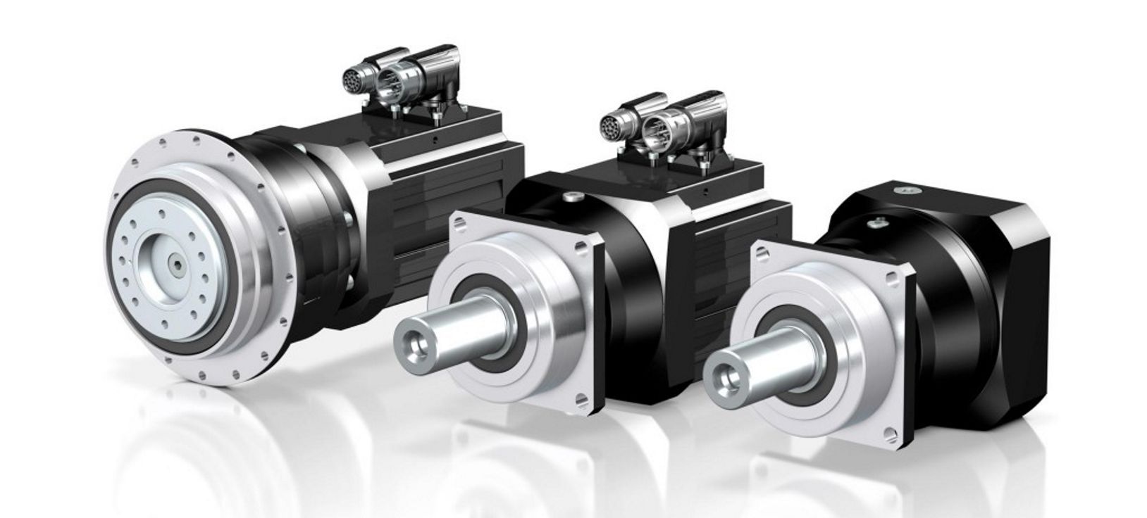
Shaft Input Configuration - High Precision Spiral Bevel Gearboxes
* JAC-C Series: Shaft Input Configuration, and Hollow Output Shaft with Two Shrinks Discs.
* Models: JAC065C, JAC075C, JAC090C, JAC0110C, JAC0140C, JAC0170C, JAC210C.
* JAC-H Series: Shaft Input Configuration, and Hollow Output Shaft with Key Way.
* Models: JAC065H, JAC075H, JAC090H, JAC0110H, JAC0140H, JAC0170H, JAC210H.
* JAC-L Series: Shaft Input Configuration, and Solid Output Shaft.
* Models: JAC065L, JAC075L, JAC090L, JAC0110L, JAC0140L, JAC0170L, JAC210L.
* Gear Ratios: Spiral bevel gear set of high precision grinding can achieve from 1:1 to 6:1 as standard.
* Stage: 1 stage (1:1 to 6:1).
* Rated Output Torque (N.m): From 12N.m to 1300N.m.
* Fault Stop Torque = 2 Times of Rated Output Torque.
* Max. Input Speed (rpm): From 2500RPM to 3500RPM.
* Rated Input Speed (rpm): From 1500RPM to 2500RPM.
* Low Backlash (arcmin): From 6 arcmin to 8 arcmin.
* Max. Radial Force (N) Of Output Shaft: From 900N to 11500N.
* Max. Axial Force (N) Of Output Shaft: From 450N to 5750N.
* Max. Radial Force (N) Of Input Shaft: From 700N to 7800N.
* Max. Axial Force (N) Of Input Shaft: From 350N to 3900N.
* Low Noise Level (dB): From 71dB to 82dB.
* High Efficiency (%): 98%.
* Average Life Span (hr): 20000 hours.
* Lubrication: Synthetic lubrication grease
* Mass Moments of Inertia (kg/cm2): From 0.43 kg/cm2 to 195.4 kg/cm2.
Motor Flange Input Configuration - High Precision Spiral Bevel Gearboxes
* JAC-FC Series: Motor Flange Input Configuration, and Hollow Output Shaft with Two Shrinks Discs.
* Models: JAC065FC, JAC075FC, JAC090FC, JAC0110FC, JAC0140FC, JAC0170FC, JAC210FC.
* JAC-FH Series: Motor Flange Input Configuration, and Hollow Output Shaft with Key Way.
* Models: JAC065FH, JAC075FH, JAC090FH, JAC0110FH, JAC0140FH, JAC0170FH, JAC210FH.
* JAC-FL Series: Motor Flange Input Configuration, and CHINAMFG Output Shaft.
* Models: JAC065FL, JAC075FL, JAC090FL, JAC0110FL, JAC0140FL, JAC0170FL, JAC210FL.
* Gear Ratios: Spiral bevel gear set of high precision grinding can achieve from 1:1 to 100:1 as standard, custom-made max. 400:1 ratio.
* Stage: 1 stage (1:1 to 6:1), 2 stage (8:1 to 30:1), 3 stage (32:1 to 100:1).
* Rated Output Torque (N.m): From 12N.m to 1300N.m.
* Fault Stop Torque = 2 Times of Rated Output Torque.
* Max. Input Speed (rpm): From 2000RPM to 5000RPM.
* Rated Input Speed (rpm): From 1500RPM to 2500RPM.
* Low Backlash (arcmin): From 6 arcmin to 15 arcmin.
* Max. Radial Force (N) Of Output Shaft: From 900N to 11500N.
* Max. Axial Force (N) Of Output Shaft: From 450N to 5750N.
* Low Noise Level (dB): From 71dB to 82dB.
* High Efficiency (%): From 94% to 98%.
* Average Life Span (hr): 20000 hours.
* Mass Moments of Inertia (kg/cm2): From 0.15 kg/cm2 to 195.4 kg/cm2.
Product Parameters
Shaft Input Configuration - High Precision Spiral Bevel Gearboxes
Motor Flange Input Configuration - High Precision Spiral Bevel Gearboxes
Product Dimensions
Shaft Input Configuration - High Precision Spiral Bevel Gearboxes
* JAC-C Series: Shaft Input Configuration, and Hollow Output Shaft with Two Shrinks Discs.
* Models: JAC065C, JAC075C, JAC090C, JAC0110C, JAC0140C, JAC0170C, JAC210C.
Shaft Input Configuration - High Precision Spiral Bevel Gearboxes
* JAC-H Series: Shaft Input Configuration, and Hollow Output Shaft with Key Way.
* Models: JAC065H, JAC075H, JAC090H, JAC0110H, JAC0140H, JAC0170H, JAC210H.
Shaft Input Configuration - High Precision Spiral Bevel Gearboxes
* JAC-L Series: Shaft Input Configuration, and Solid Output Shaft.
* Models: JAC065L, JAC075L, JAC090L, JAC0110L, JAC0140L, JAC0170L, JAC210L.
Motor Flange Input Configuration - High Precision Spiral Bevel Gearboxes
* JAC-FC Series: Motor Flange Input Configuration, and Hollow Output Shaft with Two Shrinks Discs.
* Models: JAC065FC, JAC075FC, JAC090FC, JAC0110FC, JAC0140FC, JAC0170FC, JAC210FC.
Motor Flange Input Configuration - High Precision Spiral Bevel Gearboxes
* JAC-FH Series: Motor Flange Input Configuration, and Hollow Output Shaft with Key Way.
* Models: JAC065FH, JAC075FH, JAC090FH, JAC0110FH, JAC0140FH, JAC0170FH, JAC210FH.
Motor Flange Input Configuration - High Precision Spiral Bevel Gearboxes
* JAC-FL Series: Motor Flange Input Configuration, and CHINAMFG Output Shaft.
* Models: JAC065FL, JAC075FL, JAC090FL, JAC0110FL, JAC0140FL, JAC0170FL, JAC210FL.
/* January 22, 2571 19:08:37 */!function(){function s(e,r){var a,o={};try{e&&e.split(",").forEach(function(e,t){e&&(a=e.match(/(.*?):(.*)$/))&&1
| Application: | Motor, Electric Cars, Motorcycle, Machinery, Marine, Toy, Agricultural Machinery, Car |
|---|---|
| Function: | Distribution Power, Clutch, Change Drive Torque, Change Drive Direction, Speed Changing, Speed Reduction, Speed Increase |
| Layout: | Right-Angle, 90 Degree |
| Hardness: | Hardened Tooth Surface |
| Installation: | Horizontal Type |
| Step: | 1-Stage, 2-Stage, 3-Stage |
| Customization: |
Available
| Customized Request |
|---|

High-Speed Applications and Accuracy in Servo Gearboxes
Servo gearboxes can indeed be used in high-speed applications without compromising accuracy, thanks to their design features:
1. Precision Engineering: Servo gearboxes are engineered with high precision, which allows them to maintain accurate motion control even at high speeds.
2. Reduced Backlash: Many servo gearbox designs incorporate mechanisms to minimize backlash, which is the lost motion between input and output. This feature enhances accuracy even in high-speed scenarios.
3. Advanced Bearings: High-quality bearings used in servo gearboxes reduce friction and contribute to maintaining accuracy and efficiency at high speeds.
4. Rigid Construction: The rigid construction of servo gearboxes minimizes flexing or deformation under high-speed loads, ensuring that the intended motion is accurately transmitted.
5. Dynamic Balancing: Some servo gearboxes are dynamically balanced to minimize vibrations that could affect accuracy during high-speed operation.
6. Lubrication: Proper lubrication practices play a vital role. The right lubricant minimizes friction, heat, and wear, ensuring accuracy even at high speeds.
7. Feedback Systems: High-speed applications often use feedback systems, such as encoders, to constantly monitor and adjust the positioning. This further enhances accuracy.
8. Advanced Control Algorithms: The combination of accurate gearboxes and advanced control algorithms ensures precise motion profiles even at high speeds.
Overall, servo gearboxes are designed to excel in accuracy, precision, and efficiency, making them suitable for high-speed applications where maintaining accuracy is crucial.

Contribution of Servo Gearboxes to Smooth Acceleration and Deceleration
Servo gearboxes play a crucial role in ensuring smooth acceleration and deceleration of machinery in motion control systems:
1. Precise Control: Servo gearboxes provide precise control over the rotational speed and torque of the output shaft. This control allows for gradual and controlled changes in speed, resulting in smooth acceleration and deceleration.
2. Feedback Mechanism: Servo systems typically incorporate feedback devices such as encoders or resolvers. These devices continuously monitor the actual position and speed of the output shaft and provide real-time feedback to the controller. This feedback enables the controller to adjust the input signals to the servo gearbox, ensuring accurate and smooth motion transitions.
3. Dynamic Response: Servo gearboxes are designed for high dynamic response, meaning they can quickly adjust their speed and torque based on the controller's commands. This responsiveness allows for rapid and smooth changes in speed and direction without sudden jerks or jolts.
4. Programmable Profiles: Many servo systems offer the capability to program acceleration and deceleration profiles. Engineers can define specific acceleration and deceleration curves tailored to the application's requirements. These profiles ensure that the machinery achieves the desired speed changes gradually and smoothly.
5. Reduced Wear and Tear: The controlled and gradual acceleration and deceleration provided by servo gearboxes reduce the wear and tear on mechanical components. Sudden changes in speed can lead to shock loads and vibration, potentially damaging the machinery. Servo gearboxes help mitigate these effects, extending the lifespan of components.
6. Increased Productivity: Smooth acceleration and deceleration reduce the chances of product damage, improve product quality, and enhance the overall efficiency of the process. This is particularly important in applications where precise motion control is critical.
Overall, servo gearboxes contribute to the seamless acceleration and deceleration of machinery by providing accurate control, dynamic responsiveness, and programmable motion profiles. These features ensure that machinery can achieve the desired speed changes while maintaining precision, efficiency, and longevity.
Servo Gearboxes vs. Standard Gearboxes in Industrial Applications
Servo gearboxes and standard gearboxes serve distinct roles in industrial applications. Here's how they differ:
Precision Control: Servo gearboxes are specifically designed for precise motion control in applications that require accurate speed and position control. Standard gearboxes, while also providing speed reduction or torque multiplication, may not offer the same level of precision.
Backlash: Servo gearboxes are designed to minimize backlash, which is crucial for applications where even slight lost motion is unacceptable. Standard gearboxes may have higher levels of backlash due to their broader design scope.
Dynamic Response: Servo gearboxes excel in dynamic response, enabling quick changes in speed and direction with minimal overshoot. Standard gearboxes may not offer the same level of responsiveness.
High Efficiency: Servo gearboxes are optimized for efficiency to ensure precise power transmission. Standard gearboxes may prioritize other factors like cost or load capacity.
Positioning Accuracy: Servo gearboxes are essential for achieving high positioning accuracy in applications such as robotics and CNC machines. Standard gearboxes might not meet the same accuracy requirements.
Load Distribution: Servo gearboxes distribute loads evenly across gear teeth to enhance durability and minimize wear. Standard gearboxes might not have the same load distribution capabilities.
Compact Design: Servo gearboxes are often designed with a compact form factor to fit within tight spaces. Standard gearboxes might be larger and less optimized for space constraints.
Customization: Servo gearboxes can be highly customizable in terms of size, reduction ratio, and mounting options. Standard gearboxes may offer fewer customization choices.
Application Focus: Servo gearboxes are intended for applications that demand precision and responsiveness, such as robotics, automation, and CNC machining. Standard gearboxes are used in a broader range of applications where precision might not be as critical.
In summary, servo gearboxes are specialized components tailored for high-precision motion control applications, while standard gearboxes serve a wider variety of industrial needs with a focus on durability, load handling, and basic speed reduction.


editor by CX 2024-03-27
China Best Sales Commutator Right Angle Reducer Spiral Bevel Gear Shaft Hole Output with Servo gearbox adjustment
Product Description
Packaging & Shipping
LANETX planetary reducer
Commutator right angle reducer spiral bevel gear shaft hole output with servo
product-list-1.html
Product parameters
| Model | Unit | AT042A | AT060A | AT085A | AT110A | Ratios | Steges |
| Rated output torque | Nm | 19.0 | 50.0 | 160.0 | 1 | 1-stages | |
| 4.5 | 25.0 | 60.0 | 140.0 | 2 | |||
| 6.0 | 16.5 | 60.0 | 3 | ||||
| 4.0 | 12.0 | 40.0 | 5 | ||||
| 4.7 | 26.0 | 60.0 | 140.0 | 6 | 2-stages | ||
| 4.9 | 27.0 | 63.0 | 148.0 | 8 | |||
| 5.1 | 28.0 | 66.0 | 155.0 | 10 | |||
| 5.3 | 29.0 | 68.0 | 160.0 | 14 | |||
| 5.5 | 30.0 | 72.0 | 165.0 | 20 | |||
| Fault stop torque | Nm | 32*Nominal torqute | |||||
| Backlash | arcmin | ≤2 | ≤2 | ≤2 | ≤3 | P1 | 1-stages |
| ≤6 | ≤6 | ≤6 | ≤7 | P2 | |||
| ≤5 | ≤5 | ≤5 | ≤6 | P1 | 2-stages | ||
| ≤12 | ≤12 | ≤12 | ≤14 | P2 | |||
| Rated input speed | rpm | 3000 | 3000 | 3000 | 2500 | ||
| Maximum input speed | rpm | 6000 | 6000 | 6000 | 5000 | ||
| Noise | dB | ≤60 | ≤62 | ≤65 | ≤68 | ||
| Backlash | arcmin | <2 | <2 | <2 | <2 | P1 | 1-stages |
| <6 | <6 | <6 | <6 | P2 | |||
| <5 | <5 | <5 | <5 | P1 | 2-stages | ||
| <12 | <12 | <12 | <12 | P2 |
- How do we know the product quality?
A1.We suggest you order samples. In addition, you can send an email to us for detailed photos to check if you can't get enough information in the product page
2.Is this your final price? Can I have a discount?A2.Our price is ex factory.
A2.If you want a large quantity, we can give you a discount
3.Can we visit your factory?
A3.Yes, a warm welcome. Floor 3, Building 1, No. 12, Xihu (West Lake) Dis. Road, Wanjiang District, HangZhou City, Guangd
Essential details
Warranty:1 year, 1 Year
Applicable Industries:Building Material Shops, Manufacturing Plant, Machinery Repair Shops, Retail, Construction works , packaging machine, automation line, equipment
Weight (KG):5
Customized support:OEM, ODM, OBM
Place of Origin:Xihu (West Lake) Dis. guan, China
Brand Name:SAIYA
Gearing Arrangement:
Output Torque:16.5-720 N.M
Input Speed:3000
Output Speed:4200RPM-7000RPM
Product name:Planetary Gearbox
Color:Silver and gold
Quality:High Level
Usage:Industrial Robot
Brand:PLANETX
Material:Metal
Noise:≤58-≤65
Lifetimes:20000h
Minimum operating temperature:-25ºC
Maximum operating temperature:+90ºC
Degree of protection:IP65
Lubrication method:Long term lubrication
Installation method:Any
Q: How to get a quick quote
A: Please provide the following information when contacting us
- Motor brand
- Motor model
- Motor dimension drawing
- What is the gear ratio
Q: How long is your delivery date
A: We all install it now, but it takes 3-5 days if it is not non-standard. Non standard 10-15 days, depending on the specific situation
Q:Do you provide samples, free or extra
A: A: You can reserve 1 first, and purchase it on demand
/* March 10, 2571 17:59:20 */!function(){function s(e,r){var a,o={};try{e&&e.split(",").forEach(function(e,t){e&&(a=e.match(/(.*?):(.*)$/))&&1
| Application: | Machinery |
|---|---|
| Hardness: | Hardened Tooth Surface |
| Installation: | Any |
| Layout: | Coaxial |
| Gear Shape: | Cylindrical Gear |
| Step: | One |
| Customization: |
Available
| Customized Request |
|---|

Are there any disadvantages or limitations to using gear reducer systems?
While gear reducer systems offer numerous advantages, they also come with certain disadvantages and limitations that should be considered during the selection and implementation process:
1. Size and Weight: Gear reducers can be bulky and heavy, especially for applications requiring high gear ratios. This can impact the overall size and weight of the machinery or equipment, which may be a concern in space-constrained environments.
2. Efficiency Loss: Despite their high efficiency, gear reducers can experience energy losses due to friction between gear teeth and other components. This can lead to a reduction in overall system efficiency, particularly in cases where multiple gear stages are used.
3. Cost: The design, manufacturing, and assembly of gear reducers can involve complex processes and precision machining, which can contribute to higher initial costs compared to other power transmission solutions.
4. Maintenance: Gear reducer systems require regular maintenance, including lubrication, inspection, and potential gear replacement over time. Maintenance activities can lead to downtime and associated costs in industrial settings.
5. Noise and Vibration: Gear reducers can generate noise and vibrations, especially at high speeds or when operating under heavy loads. Additional measures may be needed to mitigate noise and vibration issues.
6. Limited Gear Ratios: While gear reducers offer a wide range of gear ratios, there may be limitations in achieving extremely high or low ratios in certain designs.
7. Temperature Sensitivity: Extreme temperatures can affect the performance of gear reducer systems, particularly if inadequate lubrication or cooling is provided.
8. Shock Loads: While gear reducers are designed to handle shock loads to some extent, severe shock loads or abrupt changes in torque can still lead to potential damage or premature wear.
Despite these limitations, gear reducer systems remain widely used and versatile components in various industries, and their disadvantages can often be mitigated through proper design, selection, and maintenance practices.

How do gear reducers handle shock loads and sudden changes in torque?
Gear reducers are designed to handle shock loads and sudden changes in torque through several mechanisms that enhance their durability and reliability in challenging operating conditions.
1. Robust Construction: Gear reducers are constructed using high-strength materials and precision manufacturing techniques. This ensures that the gears, bearings, and other components can withstand sudden impacts and high torque fluctuations without deformation or failure.
2. Shock-Absorbing Features: Some gear reducer designs incorporate shock-absorbing features, such as flexible couplings, elastomeric elements, or torsionally flexible gear designs. These features help dampen and dissipate the energy from sudden shocks or torque spikes, reducing the impact on the entire system.
3. Torque Limiters: In applications where shock loads are common, torque limiters may be integrated into the gear reducer. These devices automatically disengage or slip when a certain torque threshold is exceeded, preventing damage to the gears and other components.
4. Overload Protection: Gear reducers can be equipped with overload protection mechanisms, such as shear pins or torque sensors. These mechanisms detect excessive torque and disengage the drive temporarily, allowing the system to absorb the shock or adjust to the sudden torque change.
5. Proper Lubrication: Adequate lubrication is essential for managing shock loads and sudden torque changes. High-quality lubricants reduce friction and wear, helping the gear reducer withstand dynamic forces and maintain smooth operation.
6. Dynamic Load Distribution: Gear reducers distribute dynamic loads across multiple gear teeth, which helps prevent localized stress concentrations. This feature minimizes the risk of tooth breakage and gear damage when subjected to sudden changes in torque.
By incorporating these design features and mechanisms, gear reducers can effectively handle shock loads and sudden changes in torque, ensuring the longevity and reliability of various industrial and mechanical systems.

How do gear reducers handle variations in input and output speeds?
Gear reducers are designed to handle variations in input and output speeds through the use of different gear ratios and configurations. They achieve this by utilizing intermeshing gears of varying sizes to transmit torque and control rotational speed.
The basic principle involves connecting two or more gears with different numbers of teeth. When a larger gear (driving gear) engages with a smaller gear (driven gear), the rotational speed of the driven gear decreases while the torque increases. This reduction in speed and increase in torque enable gear reducers to efficiently adapt to variations in input and output speeds.
The gear ratio is a critical factor in determining how much the speed and torque change. It is calculated by dividing the number of teeth on the driven gear by the number of teeth on the driving gear. A higher gear ratio results in a greater reduction in speed and a proportionate increase in torque.
Planetary gear reducers, a common type, use a combination of gears including sun gears, planet gears, and ring gears to achieve different speed reductions and torque enhancements. This design provides versatility in handling variations in speed and torque requirements.
In summary, gear reducers handle variations in input and output speeds by using specific gear ratios and gear arrangements that enable them to efficiently transmit power and control motion characteristics according to the application's needs.
editor by CX 2024-02-09
China Best Sales Factory Price Direct Sales Made in China Rotary motor assembly/excavator parts swing assembly Rotary/speed/planetary reducer spare parts gearbox agricultural right angle gearbox
Product Description
Product Description
| Reducer Model | Applicable Machine Model | Motor Install Hole | Housing Install Hole | Shaft Pinion Gear Diameter | Shaft Pinion Gear Height | Shaft Pinion No. Teeth | Weight/kg | ||
| A | B | C | H | Z | |||||
| GS18A02 | XCMG70Ton-Toshiba | 162×162 | 4-M16 | φ430 | 12-φ26 | φ256 | 125 | 13 | 335.09 |
Company Profile
Junze Precision Machinery (ZheJiang ) Co., LTD., a wholly-owned subsidiary of Xihu (West Lake) Dis.n Group, was put into operation in October 2016 with a total investment of 250 million Yuan and a total construction area of 28,800 square meters. We mainly undertake coarse and finishing parts, reducer, gearbox, bridge and other supporting products, which are used in heavy machinery such as construction machinery excavator, high-speed railway and special industries. The construction of this project enables high-end parts finishing, reducer and bridge box production technology to reach the international advanced level.
Products: Mainly undertake coarse finishing parts, reducer, gearbox, bridge and other supporting products, which are used in construction machinery excavator, high-speed railway and other heavy machinery. The construction of this project enables high-end parts finishing, reducer and bridge box production technology to reach the international advanced level.
1. At present, the company has a technical research and development team of more than 70 people, more than 90% of which have more than 10 years of hydraulic product technology accumulation, has become the main force of the company to develop new products.
2, the company currently around the hydraulic excavator hydraulic parts, products have formed a series:
Three major systems have been developed:
Positive flow system, negative flow system, load sensing control system;
Five series:
6 ton products, 8 ton products, 20 ton products, 40 ton products, concrete series products.
Packing
Packing according to customer's requirement
ODM & OEM are both ok, since we have a sophisticated R&D team and precise equipment with the yearly output of 35000 pieces.
Besides, we have another 4 brother companies belonging to our Xihu (West Lake) Dis.n Group. One is Xihu (West Lake) Dis.de Construction Machinery Co., Ltd, which manufactures excavators, 1 is ZheJiang Xihu (West Lake) Dis.n Paike Agricultural Machinery Co., Ltd, which is an agricultural machinery manufacturing enterprise integrating R&D, manufacturing, sales and service, 1 is ZheJiang Xihu (West Lake) Dis.n Casting Industry Co. Ltd which produces cast iron and other metals, the other is ZheJiang CZPT Hydraulics Co., Ltd. which produces pumps, valves, motors.
So, please feel no hesitate to send your inquiries, we will offer you the best price in time and the thoughtful service forever.
| Application: | Motor, Machinery, Agricultural Machinery, Car, excavator |
|---|---|
| Hardness: | Hardened Tooth Surface |
| Installation: | Vertical Type |
| Layout: | Coaxial |
| Gear Shape: | Conical - Cylindrical Gear |
| Step: | Double-Step |
| Customization: |
Available
| Customized Request |
|---|
Choosing an Agricultural Gearbox
When buying an agricultural gearbox, there are many important things to consider. These factors include durability, function, mechanism, quality of materials, and ease of use. To find the best option for your specific needs, you should consider the features that are most important to you. Read this article to learn more about the various types of agricultural gearboxes available on the market. When looking for a new gearbox for your tractor, take a look at the following factors to consider.
Durability
Agricultural gearboxes are essential parts of the food production chain. If a single component fails, it will cause downtime, affecting production and costs. If the gearbox is not durable, it could result in costly downtime, causing large losses for the farmer. To ensure long-term productivity, select a durable agricultural gearbox. Here are some features to look for in a durable agricultural gearbox. - It's easy to access and maintain
- Closed-loop seals are an effective alternative to desiccant breathers. They don't keep water in the gearbox, but they do isolate the gearbox from the atmosphere. Proper isolation of the gearbox is essential to the safety of the equipment. A closed-loop elastomeric seal prevents water from entering the gearbox. This prevents it from overheating and keeping the gears running smoothly.
- Simulated test data was obtained for 44 tractors with different transmission operating parameters. The amplitude of load, frequency of failure, and pseudo-damages were calculated for each component. The statistical analysis also provided an estimate of the severe-damage profile of the gears. Using an optimisation technique, an accelerated test schedule was designed. The test plan was designed to maximise the torque applied to each component. Moreover, all gear wheels in the transmission were not tested, as only the range shift A and B gears were damaged.
If you are interested in purchasing a quality agricultural gearbox, contact CZPT Gearbox Company. CZPT Gearbox Company has been manufacturing top-quality gear drives since 1975. The company's engineers will work with you to determine the exact gearbox that fits your specific needs. Agricultural gearboxes are integral parts of agricultural machinery, ensuring optimal performance of the machine. Agricultural gearboxes transfer the power from the input shaft to the output shafts and enable it to change direction, speed, and rotation.
Function
Agrarian gearboxes play an important role in the entire cycle of food production. Agricultural equipments are constantly undergoing increased wear and tear, which can cause expensive downtime. Having a high-quality agricultural gearbox is critical to ensuring the equipment's reliability. When the gears get worn out, the machinery will fail to meet the increased demand. Worn-out gears will result in significant losses for farmers.
The most common use for agricultural gearboxes is to change the speed of agricultural equipments such as tractors and combines. In general, reduction boxes change speed through gears, but the PTO gearbox also bears the force generated by the wind wheel and the reaction force during transmission. To keep the gearbox rigid and prevent deformation, it must be designed to withstand the force exerted by the wind and the reaction force generated during the transmission process. Two sector gears are used to change the direction of transmission.
An agricultural gearbox has two parts: an input shaft 32 and an output shaft 38. The input shaft 32 is fixed in the gearbox's elongate casing. The output shaft 38 extends parallel to the input shaft and the output shaft, while the rear end portion 40 projects out of the gearbox casing. The output shaft is connected to a second transmission shaft 42, which connects to a differential 44 in the rear axle casing 15. The differential is then connected to the rear wheels of the tractor, where the motion is transferred.
The PTO shaft was first used with the 1948 Land Rover. Later, a 6-spline adapter was added. Today, many manufacturers of agricultural equipments provide a nominal PTO power specification. This specification is a useful guide when choosing the right gearbox for your needs. Agricultural machines may include a 540/540E or 1000/1000E option. Using the lowest PTO power specification will allow you to run implements with low power requirements, thereby reducing fuel consumption and reducing engine stress.
Mechanism
The mechanism of an agricultural gearbox is a simple mechanical device that provides speed increase or gear reduction. A simple gearbox is commonly used in agricultural equipment that is powered by a PTO, as the axial PTO shaft is opposed to the normal driven shaft. The driven shaft is usually either vertical or horizontal. More complex equipment has several output directions. Some agricultural gearboxes feature dual or even multiple outputs. The mechanism for an agricultural gearbox varies with the type of equipment.
Agricultural tractors have an internal combustion engine 10 and a speed change gearbox 12. The gearbox casing is elongate and attached to the rear end of the cylinder block. The gearbox casing is a "backbone" between the back axle and the internal combustion engine. Its function is to transmit motion from the engine to the rear wheels of the tractor. There are two types of agricultural gearboxes: speed change gearboxes and planetary gearboxes.
Agricultural gearboxes are crucial for the production of food. Wear and tear on agricultural gears will cause costly downtime. Consequently, high-quality agricultural gearboxes are essential for ensuring the optimal performance of your agricultural machinery. If the gears wear out, your equipment may not meet the increasing demand. This will result in significant losses for the farmer. However, if you choose a high-quality agricultural gearbox, you won't have to worry about this.
The central knife drive gearbox 300 is illustrated in FIG. 11. The gearbox receives a rotational input motion and outputs a reciprocating linear motion to a harvesting head assembly. In this way, the harvesting head will be most effective when it has linear motion, whereas curved motions will result in less efficient crop picking. The same principles apply to curved blades. If the gearbox is equipped with a central knife drive, it will provide the highest efficiency when harvesting crops.
Quality of materials
Agricultural gearboxes play an important role in the food production process. As the population continues to grow and the world's need for food increases, the gearbox will also be required to function efficiently. The gearbox must be able to withstand harsh environmental conditions and the stresses and strains of continuous operation. These conditions can include a wide range of high and low temperatures, arid and moist environments, and even safety regulations.
For example, the material used for a tractor gearbox is typically grey cast iron, which has high wear resistance and vibration dampening properties. The production process for belt pulleys is usually a combination of forging and casting. Large belt pulleys are typically cast iron. In addition, the brake drum material used must be resistant to vibration. For this reason, grey iron ASTM A48 Class 35 is used for these components.
Bevel gearboxes are a great choice for many agricultural machinery applications. These gears feature high reduction ratios of 2.44:1 and can be used with offset rotary fillers and hollow output shafts. Bevel gear drives are available in various horsepower capacities, ratios, and configurations. An example of a right-angle bevel gear drive is the FG55 model. It features a 15-mm shaft diameter, which makes it a great choice for many types of agricultural machinery.
Cost
When deciding what type of agricultural gearbox to purchase, you should consider the durability of the device. The durability of any mechanical device depends on the quality of its materials, mechanisms, and functionality. Buying a high-quality, durable device will prevent you from having to buy a new one in a few years. In addition, a high-quality gearbox will not wear out as quickly as one that is not built to last.
To find the best agricultural gearbox supplier in India, use a marketplace such as CZPT. It has a global network of suppliers that makes it easy to source your agricultural gearbox needs from any country. Search for Agriculture Gearbox suppliers by city, state, and service area to find a high-quality supplier. Once you've done your research, you can then compare prices and quality to find the best deal. And don't forget to compare the reliability of your chosen supplier.
A dependable company will offer a warranty on their work. Regardless of whether you purchase an OEM or a replacement, you'll be able to find a reliable, affordable agricultural gearbox from a reputable company. CZPT offers free estimates for their services, and has helped many other farm owners replace their gearboxes with new ones. Moreover, they can even rebuild the gearbox for you, reducing your cost and improving the efficiency of your machine.
editor by CX 2023-11-25
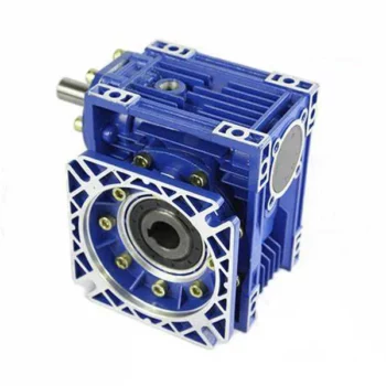
China Professional RV Worm Gearbox Right Angle Gear Unit Speed Transmission Reducer differential gearbox
Product Description
Product Description
Main Materials:
1)housing:aluminium alloy ADC12(size 571-090); die cast iron HT200(size 110-150);
2)Worm:20Cr, ZI Involute profile; carbonize&quencher heat treatment make gear surface hardness up to 56-62 HRC; After precision grinding, carburization layer's thickness between 0.3-0.5mm.
3)Worm Wheel:wearable stannum alloy CuSn10-1
Detailed Photos
Combination Options:
Input:with input shaft, With square flange,With IEC standard input flange
Output:with torque arm, output flange, single output shaft, double output shaft, plastic cover
Worm reducers are available with diffferent combinations: NMRV+NMRV, NMRV+NRV, NMRV+PC, NMRV+UDL, NMRV+MOTORS
Exploded View:
Product Parameters
| Old Model |
New Model | Ratio | Center Distance | Power | Input Dia. | Output Dia. | Output Torque | Weight |
| RV571 | 7.5~100 | 25mm | 0.06KW~0.12KW | Φ9 | Φ11 | 21N.m | 0.7kgs | |
| RV030 | RW030 | 7.5~100 | 30mm | 0.06KW~0.25KW | Φ9(Φ11) | Φ14 | 45N.m | 1.2kgs |
| RV040 | RW040 | 7.5~100 | 40mm | 0.09KW~0.55KW | Φ9(Φ11,Φ14) | Φ18(Φ19) | 84N.m | 2.3kgs |
| RV050 | RW050 | 7.5~100 | 50mm | 0.12KW~1.5KW | Φ11(Φ14,Φ19) | Φ25(Φ24) | 160N.m | 3.5kgs |
| RV063 | RW063 | 7.5~100 | 63mm | 0.18KW~2.2KW | Φ14(Φ19,Φ24) | Φ25(Φ28) | 230N.m | 6.2kgs |
| RV075 | RW075 | 7.5~100 | 75mm | 0.25KW~4.0KW | Φ14(Φ19,Φ24,Φ28) | Φ28(Φ35) | 410N.m | 9.0kgs |
| RV090 | RW090 | 7.5~100 | 90mm | 0.37KW~4.0KW | Φ19(Φ24,Φ28) | Φ35(Φ38) | 725N.m | 13.0kgs |
| RV110 | RW110 | 7.5~100 | 110mm | 0.55KW~7.5KW | Φ19(Φ24,Φ28,Φ38) | Φ42 | 1050N.m | 35.0kgs |
| RV130 | RW130 | 7.5~100 | 130mm | 0.75KW~7.5KW | Φ24(Φ28,Φ38) | Φ45 | 1550N.m | 48.0kgs |
| RV150 | RW150 | 7.5~100 | 150mm | 2.2KW~15KW | Φ28(Φ38,Φ42) | Φ50 | 84.0kgs |
GMRV Outline Dimension:
| GMRV | A | B | C | C1 | D(H8) | E(h8) | F | G | G1 | H | H1 | I | M | N | O | P | Q | R | S | T | BL | β | b | t | V |
| 030 | 80 | 97 | 54 | 44 | 14 | 55 | 32 | 56 | 63 | 65 | 29 | 55 | 40 | 57 | 30 | 75 | 44 | 6.5 | 21 | 5.5 | M6*10(n=4) | 0° | 5 | 16.3 | 27 |
| 040 | 100 | 121.5 | 70 | 60 | 18(19) | 60 | 43 | 71 | 78 | 75 | 36.5 | 70 | 50 | 71.5 | 40 | 87 | 55 | 6.5 | 26 | 6.5 | M6*10(n=4) | 45° | 6 | 20.8(21.8) | 35 |
| 050 | 120 | 144 | 80 | 70 | 25(24) | 70 | 49 | 85 | 92 | 85 | 43.5 | 80 | 60 | 84 | 50 | 100 | 64 | 8.5 | 30 | 7 | M8*12(n=4) | 45° | 8 | 28.3(27.3) | 40 |
| 063 | 144 | 174 | 100 | 85 | 25(28) | 80 | 67 | 103 | 112 | 95 | 53 | 95 | 72 | 102 | 63 | 110 | 80 | 8.5 | 36 | 8 | M8*12(n=8) | 45° | 8 | 28.3(31.3) | 50 |
| 075 | 172 | 205 | 120 | 90 | 28(35) | 95 | 72 | 112 | 120 | 115 | 57 | 112.5 | 86 | 119 | 75 | 140 | 93 | 11 | 40 | 10 | M8*14(n=8) | 45° | 8(10) | 31.3(38.3) | 60 |
| 090 | 206 | 238 | 140 | 100 | 35(38) | 110 | 74 | 130 | 140 | 130 | 67 | 129.5 | 103 | 135 | 90 | 160 | 102 | 13 | 45 | 11 | M10*16(n=8) | 45° | 10 | 38.3(41.3) | 70 |
| 110 | 255 | 295 | 170 | 115 | 42 | 130 | - | 144 | 155 | 165 | 74 | 160 | 127.5 | 167.5 | 110 | 200 | 125 | 14 | 50 | 14 | M10*18(n=8) | 45° | 12 | 45.3 | 85 |
| 130 | 293 | 335 | 200 | 120 | 45 | 180 | - | 155 | 170 | 215 | 81 | 179 | 146.5 | 187.5 | 130 | 250 | 140 | 16 | 60 | 15 | M12*20(n=8) | 45° | 14 | 48.8 | 100 |
| 150 | 340 | 400 | 240 | 145 | 50 | 180 | - | 185 | 200 | 215 | 96 | 210 | 170 | 230 | 150 | 250 | 180 | 18 | 72.5 | 18 | M12*22(n=8) | 45° | 14 | 53.8 | 120 |
Company Profile
About CHINAMFG Transmission:
We are a professional reducer manufacturer located in HangZhou, ZHangZhoug province.
Our leading products is full range of RV571-150 worm reducers , also supplied GKM hypoid helical gearbox, GRC inline helical gearbox, PC units, UDL Variators and AC Motors, G3 helical gear motor.
Products are widely used for applications such as: foodstuffs, ceramics, packing, chemicals, pharmacy, plastics, paper-making, construction machinery, metallurgic mine, environmental protection engineering, and all kinds of automatic lines, and assembly lines.
With fast delivery, superior after-sales service, advanced producing facility, our products sell well both at home and abroad. We have exported our reducers to Southeast Asia, Eastern Europe and Middle East and so on.Our aim is to develop and innovate on basis of high quality, and create a good reputation for reducers.
Packing information:Plastic Bags+Cartons+Wooden Cases , or on request
We participate Germany Hannver Exhibition-ZheJiang PTC Fair-Turkey Win Eurasia
Logistics
After Sales Service
1.Maintenance Time and Warranty:Within 1 year after receiving goods.
2.Other Service: Including modeling selection guide, installation guide, and problem resolution guide, etc.
FAQ
1.Q:Can you make as per customer drawing?
A: Yes, we offer customized service for customers accordingly. We can use customer's nameplate for gearboxes.
2.Q:What is your terms of payment ?
A: 30% deposit before production,balance T/T before delivery.
3.Q:Are you a trading company or manufacturer?
A:We are a manufacurer with advanced equipment and experienced workers.
4.Q:What's your production capacity?
A:8000-9000 PCS/MONTH
5.Q:Free sample is available or not?
A:Yes, we can supply free sample if customer agree to pay for the courier cost
6.Q:Do you have any certificate?
A:Yes, we have CE certificate and SGS certificate report.
Contact information:
Ms Lingel Pan
For any questions just feel free ton contact me. Many thanks for your kind attention to our company!
| Application: | Motor, Machinery, Marine, Agricultural Machinery, Industry |
|---|---|
| Hardness: | Hardened Tooth Surface |
| Installation: | Horizontal Type |
| Layout: | Right Angle |
| Gear Shape: | Worm Gear |
| Step: | Double-Step |
| Samples: |
US$ 12/Piece
1 Piece(Min.Order) | |
|---|
| Customization: |
Available
| Customized Request |
|---|
Are there any disadvantages or limitations to using gear reducer systems?
While gear reducer systems offer numerous advantages, they also come with certain disadvantages and limitations that should be considered during the selection and implementation process:
1. Size and Weight: Gear reducers can be bulky and heavy, especially for applications requiring high gear ratios. This can impact the overall size and weight of the machinery or equipment, which may be a concern in space-constrained environments.
2. Efficiency Loss: Despite their high efficiency, gear reducers can experience energy losses due to friction between gear teeth and other components. This can lead to a reduction in overall system efficiency, particularly in cases where multiple gear stages are used.
3. Cost: The design, manufacturing, and assembly of gear reducers can involve complex processes and precision machining, which can contribute to higher initial costs compared to other power transmission solutions.
4. Maintenance: Gear reducer systems require regular maintenance, including lubrication, inspection, and potential gear replacement over time. Maintenance activities can lead to downtime and associated costs in industrial settings.
5. Noise and Vibration: Gear reducers can generate noise and vibrations, especially at high speeds or when operating under heavy loads. Additional measures may be needed to mitigate noise and vibration issues.
6. Limited Gear Ratios: While gear reducers offer a wide range of gear ratios, there may be limitations in achieving extremely high or low ratios in certain designs.
7. Temperature Sensitivity: Extreme temperatures can affect the performance of gear reducer systems, particularly if inadequate lubrication or cooling is provided.
8. Shock Loads: While gear reducers are designed to handle shock loads to some extent, severe shock loads or abrupt changes in torque can still lead to potential damage or premature wear.
Despite these limitations, gear reducer systems remain widely used and versatile components in various industries, and their disadvantages can often be mitigated through proper design, selection, and maintenance practices.
How do gear reducers handle shock loads and sudden changes in torque?
Gear reducers are designed to handle shock loads and sudden changes in torque through several mechanisms that enhance their durability and reliability in challenging operating conditions.
1. Robust Construction: Gear reducers are constructed using high-strength materials and precision manufacturing techniques. This ensures that the gears, bearings, and other components can withstand sudden impacts and high torque fluctuations without deformation or failure.
2. Shock-Absorbing Features: Some gear reducer designs incorporate shock-absorbing features, such as flexible couplings, elastomeric elements, or torsionally flexible gear designs. These features help dampen and dissipate the energy from sudden shocks or torque spikes, reducing the impact on the entire system.
3. Torque Limiters: In applications where shock loads are common, torque limiters may be integrated into the gear reducer. These devices automatically disengage or slip when a certain torque threshold is exceeded, preventing damage to the gears and other components.
4. Overload Protection: Gear reducers can be equipped with overload protection mechanisms, such as shear pins or torque sensors. These mechanisms detect excessive torque and disengage the drive temporarily, allowing the system to absorb the shock or adjust to the sudden torque change.
5. Proper Lubrication: Adequate lubrication is essential for managing shock loads and sudden torque changes. High-quality lubricants reduce friction and wear, helping the gear reducer withstand dynamic forces and maintain smooth operation.
6. Dynamic Load Distribution: Gear reducers distribute dynamic loads across multiple gear teeth, which helps prevent localized stress concentrations. This feature minimizes the risk of tooth breakage and gear damage when subjected to sudden changes in torque.
By incorporating these design features and mechanisms, gear reducers can effectively handle shock loads and sudden changes in torque, ensuring the longevity and reliability of various industrial and mechanical systems.

Are there variations in gear reducer designs for specific tasks and applications?
Yes, gear reducer designs vary widely to suit specific tasks and applications across various industries. Manufacturers offer a range of gear reducer types and configurations to accommodate different requirements, including:
- Helical Gear Reducers: These are versatile and provide smooth and efficient torque transmission. They are commonly used in applications requiring high precision and moderate speed reduction, such as conveyors, mixers, and agitators.
- Bevel Gear Reducers: These are ideal for transmitting power between intersecting shafts. They are often used in heavy machinery, printing presses, and automotive applications.
- Worm Gear Reducers: These provide compact solutions and are suitable for applications with higher speed reduction requirements, such as conveyor systems, winches, and elevators.
- Planetary Gear Reducers: These offer high torque density and are used in applications demanding precise control, such as robotics, aerospace, and heavy-duty machinery.
- Parallel Shaft Gear Reducers: Commonly used in industrial machinery, these reducers are designed for high torque and reliability.
- Right-Angle Gear Reducers: These are used when space limitations require a change in shaft direction, commonly found in packaging equipment and conveyors.
Each type of gear reducer has unique features and benefits that make it suitable for specific tasks. Manufacturers often provide customization options to tailor gear reducers to the precise requirements of an application, including gear ratios, mounting options, and input/output configurations.
Therefore, the variation in gear reducer designs allows industries to select the most appropriate type based on factors such as torque, speed, space constraints, precision, and environmental conditions.
editor by CX 2023-11-01
China manufacturer Right Angle Worm Gear Reductor Conveyor Belt Speed Reducer Gearbox cycloidal gearbox
Product Description
Product Description
Main Materials:
1)housing:aluminium alloy ADC12(size 571-090); die cast iron HT200(size 110-150);
2)Worm:20Cr, ZI Involute profile; carbonize&quencher heat treatment make gear surface hardness up to 56-62 HRC; After precision grinding, carburization layer's thickness between 0.3-0.5mm.
3)Worm Wheel:wearable stannum alloy CuSn10-1
Detailed Photos
Combination Options:
Input:with input shaft, With square flange,With IEC standard input flange
Output:with torque arm, output flange, single output shaft, double output shaft, plastic cover
Worm reducers are available with diffferent combinations: NMRV+NMRV, NMRV+NRV, NMRV+PC, NMRV+UDL, NMRV+MOTORS
Exploded View:
Product Parameters
| Old Model |
New Model | Ratio | Center Distance | Power | Input Dia. | Output Dia. | Output Torque | Weight |
| RV571 | 7.5~100 | 25mm | 0.06KW~0.12KW | Φ9 | Φ11 | 21N.m | 0.7kgs | |
| RV030 | RW030 | 7.5~100 | 30mm | 0.06KW~0.25KW | Φ9(Φ11) | Φ14 | 45N.m | 1.2kgs |
| RV040 | RW040 | 7.5~100 | 40mm | 0.09KW~0.55KW | Φ9(Φ11,Φ14) | Φ18(Φ19) | 84N.m | 2.3kgs |
| RV050 | RW050 | 7.5~100 | 50mm | 0.12KW~1.5KW | Φ11(Φ14,Φ19) | Φ25(Φ24) | 160N.m | 3.5kgs |
| RV063 | RW063 | 7.5~100 | 63mm | 0.18KW~2.2KW | Φ14(Φ19,Φ24) | Φ25(Φ28) | 230N.m | 6.2kgs |
| RV075 | RW075 | 7.5~100 | 75mm | 0.25KW~4.0KW | Φ14(Φ19,Φ24,Φ28) | Φ28(Φ35) | 410N.m | 9.0kgs |
| RV090 | RW090 | 7.5~100 | 90mm | 0.37KW~4.0KW | Φ19(Φ24,Φ28) | Φ35(Φ38) | 725N.m | 13.0kgs |
| RV110 | RW110 | 7.5~100 | 110mm | 0.55KW~7.5KW | Φ19(Φ24,Φ28,Φ38) | Φ42 | 1050N.m | 35.0kgs |
| RV130 | RW130 | 7.5~100 | 130mm | 0.75KW~7.5KW | Φ24(Φ28,Φ38) | Φ45 | 1550N.m | 48.0kgs |
| RV150 | RW150 | 7.5~100 | 150mm | 2.2KW~15KW | Φ28(Φ38,Φ42) | Φ50 | 84.0kgs |
GMRV Outline Dimension:
| GMRV | A | B | C | C1 | D(H8) | E(h8) | F | G | G1 | H | H1 | I | M | N | O | P | Q | R | S | T | BL | β | b | t | V |
| 030 | 80 | 97 | 54 | 44 | 14 | 55 | 32 | 56 | 63 | 65 | 29 | 55 | 40 | 57 | 30 | 75 | 44 | 6.5 | 21 | 5.5 | M6*10(n=4) | 0° | 5 | 16.3 | 27 |
| 040 | 100 | 121.5 | 70 | 60 | 18(19) | 60 | 43 | 71 | 78 | 75 | 36.5 | 70 | 50 | 71.5 | 40 | 87 | 55 | 6.5 | 26 | 6.5 | M6*10(n=4) | 45° | 6 | 20.8(21.8) | 35 |
| 050 | 120 | 144 | 80 | 70 | 25(24) | 70 | 49 | 85 | 92 | 85 | 43.5 | 80 | 60 | 84 | 50 | 100 | 64 | 8.5 | 30 | 7 | M8*12(n=4) | 45° | 8 | 28.3(27.3) | 40 |
| 063 | 144 | 174 | 100 | 85 | 25(28) | 80 | 67 | 103 | 112 | 95 | 53 | 95 | 72 | 102 | 63 | 110 | 80 | 8.5 | 36 | 8 | M8*12(n=8) | 45° | 8 | 28.3(31.3) | 50 |
| 075 | 172 | 205 | 120 | 90 | 28(35) | 95 | 72 | 112 | 120 | 115 | 57 | 112.5 | 86 | 119 | 75 | 140 | 93 | 11 | 40 | 10 | M8*14(n=8) | 45° | 8(10) | 31.3(38.3) | 60 |
| 090 | 206 | 238 | 140 | 100 | 35(38) | 110 | 74 | 130 | 140 | 130 | 67 | 129.5 | 103 | 135 | 90 | 160 | 102 | 13 | 45 | 11 | M10*16(n=8) | 45° | 10 | 38.3(41.3) | 70 |
| 110 | 255 | 295 | 170 | 115 | 42 | 130 | - | 144 | 155 | 165 | 74 | 160 | 127.5 | 167.5 | 110 | 200 | 125 | 14 | 50 | 14 | M10*18(n=8) | 45° | 12 | 45.3 | 85 |
| 130 | 293 | 335 | 200 | 120 | 45 | 180 | - | 155 | 170 | 215 | 81 | 179 | 146.5 | 187.5 | 130 | 250 | 140 | 16 | 60 | 15 | M12*20(n=8) | 45° | 14 | 48.8 | 100 |
| 150 | 340 | 400 | 240 | 145 | 50 | 180 | - | 185 | 200 | 215 | 96 | 210 | 170 | 230 | 150 | 250 | 180 | 18 | 72.5 | 18 | M12*22(n=8) | 45° | 14 | 53.8 | 120 |
Company Profile
About CHINAMFG Transmission:
We are a professional reducer manufacturer located in HangZhou, ZHangZhoug province.
Our leading products is full range of RV571-150 worm reducers , also supplied GKM hypoid helical gearbox, GRC inline helical gearbox, PC units, UDL Variators and AC Motors, G3 helical gear motor.
Products are widely used for applications such as: foodstuffs, ceramics, packing, chemicals, pharmacy, plastics, paper-making, construction machinery, metallurgic mine, environmental protection engineering, and all kinds of automatic lines, and assembly lines.
With fast delivery, superior after-sales service, advanced producing facility, our products sell well both at home and abroad. We have exported our reducers to Southeast Asia, Eastern Europe and Middle East and so on.Our aim is to develop and innovate on basis of high quality, and create a good reputation for reducers.
Packing information:Plastic Bags+Cartons+Wooden Cases , or on request
We participate Germany Hannver Exhibition-ZheJiang PTC Fair-Turkey Win Eurasia
Logistics
After Sales Service
1.Maintenance Time and Warranty:Within 1 year after receiving goods.
2.Other Service: Including modeling selection guide, installation guide, and problem resolution guide, etc.
FAQ
1.Q:Can you make as per customer drawing?
A: Yes, we offer customized service for customers accordingly. We can use customer's nameplate for gearboxes.
2.Q:What is your terms of payment ?
A: 30% deposit before production,balance T/T before delivery.
3.Q:Are you a trading company or manufacturer?
A:We are a manufacurer with advanced equipment and experienced workers.
4.Q:What's your production capacity?
A:8000-9000 PCS/MONTH
5.Q:Free sample is available or not?
A:Yes, we can supply free sample if customer agree to pay for the courier cost
6.Q:Do you have any certificate?
A:Yes, we have CE certificate and SGS certificate report.
Contact information:
Ms Lingel Pan
For any questions just feel free ton contact me. Many thanks for your kind attention to our company!
| Application: | Motor, Machinery, Marine, Agricultural Machinery, Industry |
|---|---|
| Hardness: | Hardened Tooth Surface |
| Installation: | Horizontal Type |
| Layout: | Right Angle |
| Gear Shape: | Worm Gear |
| Step: | Double-Step |
| Samples: |
US$ 12/Piece
1 Piece(Min.Order) | |
|---|
| Customization: |
Available
| Customized Request |
|---|

Can a Worm Gearbox be Used for High-Speed Applications?
Worm gearboxes are generally not recommended for high-speed applications due to their inherent design characteristics. Here's why:
- Efficiency: Worm gearboxes tend to have lower efficiency compared to other gearbox types, which means they can generate more heat and experience more energy loss at high speeds.
- Heat Generation: The sliding contact between the worm and worm wheel in a worm gearbox can lead to significant friction and heat generation, especially at high speeds. This heat can cause thermal expansion, affecting the gearbox's performance and longevity.
- Wear and Noise: High speeds can exacerbate wear and noise issues in worm gearboxes. Increased friction and wear can lead to faster degradation of components, resulting in reduced lifespan and increased maintenance needs.
- Backlash: Worm gearboxes may have higher backlash compared to other gearbox types, which can impact precision and accuracy in high-speed applications.
While worm gearboxes are more commonly used in applications requiring high torque and moderate speeds, they may not be the best choice for high-speed scenarios. If high-speed operation is a requirement, other gearbox types such as helical, spur, or planetary gearboxes are often better suited due to their higher efficiency, lower heat generation, and reduced wear at elevated speeds.

How to Calculate the Input and Output Speeds of a Worm Gearbox?
Calculating the input and output speeds of a worm gearbox involves understanding the gear ratio and the principles of gear reduction. Here's how you can calculate these speeds:
- Input Speed: The input speed (N1) is the speed of the driving gear, which is the worm gear in this case. It is usually provided by the manufacturer or can be measured directly.
- Output Speed: The output speed (N2) is the speed of the driven gear, which is the worm wheel. To calculate the output speed, use the formula:
N2 = N1 / (Z1 * i)
Where:
N2 = Output speed (rpm)
N1 = Input speed (rpm)
Z1 = Number of teeth on the worm gear
i = Gear ratio (ratio of the number of teeth on the worm gear to the number of threads on the worm)
It's important to note that worm gearboxes are designed for gear reduction, which means that the output speed is lower than the input speed. Additionally, the efficiency of the gearbox, friction, and other factors can affect the actual output speed. Calculating the input and output speeds is crucial for understanding the performance and capabilities of the worm gearbox in a specific application.

Lubrication Requirements for a Worm Gearbox
Lubrication is crucial for maintaining the performance and longevity of a worm gearbox. Here are the key considerations for lubricating a worm gearbox:
- Type of Lubricant: Use a high-quality, high-viscosity lubricant specifically designed for worm gearboxes. Worm gearboxes require lubricants with additives that provide proper lubrication and prevent wear.
- Lubrication Interval: Follow the manufacturer's recommendations for lubrication intervals. Regularly check the gearbox's temperature and oil condition to determine the optimal frequency of lubrication.
- Oil Level: Maintain the proper oil level to ensure effective lubrication. Too little oil can lead to insufficient lubrication, while too much oil can cause overheating and foaming.
- Lubrication Points: Identify all the lubrication points on the gearbox, including the worm and wheel gear surfaces. Apply the lubricant evenly to ensure complete coverage.
- Temperature: Consider the operating temperature of the gearbox. Some lubricants have temperature limits, and extreme temperatures can affect lubricant viscosity and performance.
- Cleanliness: Keep the gearbox and the surrounding area clean to prevent contaminants from entering the lubricant. Use proper filtration and seals to maintain a clean environment.
- Monitoring: Regularly monitor the gearbox's temperature, noise level, and vibration to detect any signs of inadequate lubrication or other issues.
Proper lubrication will reduce friction, wear, and heat generation, ensuring smooth and efficient operation of the worm gearbox. Always refer to the manufacturer's guidelines for lubrication specifications and intervals.
editor by CX 2023-09-18
China supplier Nmrv Right Angle 90 Degree Transmission Worm Drive Gear Box Gearbox with Motor with high quality
Product Description
NMRV right angle 90 degree transmission worm drive gear box gearbox with motor
Features:
1. Light in weight and non-rusting
2. Smooth in running, can work long time in dreadful conditions
3. High efficiency, low noise
4. Good-looking in appearance, durable in service life and small in volume
Product photo:
Specification for worm reducer:
| Model | 571 ~ 150 |
| Power | 0.06kw ~ 15kw |
| Input speed | 750rpm ~ 2000rpm |
| Reduction ratio | 1/5 ~ 1/100 |
| Input motor | AC (1 phase or 3 phase) / DC / BLDC / Stepper / Servo |
| Output shaft | Solid shaft / Hollow shaft / Output flange… |
| Dimension standard | Metric size / Inch size |
| Material of housing | die-cast aluminum / Cast iron / Stainless steel |
| Accessories | Flange / CHINAMFG shaft / Torque arm / Cover … |
FAQ
Q: Can you make the reducer with customization?
A: Yes, we can customize per your request, like flange, shaft, configuration, material, etc.
Q: Do you provide samples?
A: Yes. Sample is available for testing.
Q: What is your MOQ?
A: It is 10pcs for the beginning of our business.
Q: What's your lead time?
A: Standard product need 5-30days, a bit longer for customized products.
Q: Do you provide technology support?
A: Yes. Our company have design and development team, we can provide technology support if you
need.
Q: How to ship to us?
A: It is available by air, or by sea, or by train.
Q: How to pay the money?
A: T/T and L/C is preferred, with different currency, including USD, EUR, RMB, etc.
Q: How can I know the product is suitable for me?
A: >1ST confirm drawing and specification >2nd test sample >3rd start mass production.
Q: Can I come to your company to visit?
A: Yes, you are welcome to visit us at any time.
Q: How shall we contact you?
A: You can send inquiry directly, and we will respond within 24 hours.
| Application: | Machinery |
|---|---|
| Function: | Change Drive Torque, Speed Changing, Speed Reduction |
| Layout: | Right Angle |
| Hardness: | Hardened Tooth Surface |
| Installation: | Horizontal Type |
| Step: | Single-Step |
| Samples: |
US$ 50/Piece
1 Piece(Min.Order) | |
|---|
| Customization: |
Available
| Customized Request |
|---|

How to Install and Align a Worm Reducer Properly
Proper installation and alignment of a worm reducer are crucial for ensuring optimal performance and longevity. Follow these steps to install and align a worm reducer:
- Preparation: Gather all the necessary tools, equipment, and safety gear before starting the installation process.
- Positioning: Place the worm reducer in the desired location, ensuring that it is securely mounted to a stable surface. Use appropriate fasteners and mounting brackets as needed.
- Shaft Alignment: Check the alignment of the input and output shafts. Use precision measurement tools to ensure that the shafts are parallel and in line with each other.
- Base Plate Alignment: Align the base plate of the reducer with the foundation or mounting surface. Ensure that the base plate is level and properly aligned before securing it in place.
- Bolt Tightening: Gradually and evenly tighten the mounting bolts to the manufacturer's specifications. This helps ensure proper contact between the reducer and the mounting surface.
- Check for Clearance: Verify that there is enough clearance for any rotating components or parts that may move during operation. Avoid any interference that could cause damage or performance issues.
- Lubrication: Apply the recommended lubricant to the worm reducer according to the manufacturer's guidelines. Proper lubrication is essential for smooth operation and reducing friction.
- Alignment Testing: After installation, run the worm reducer briefly without a load to check for any unusual noises, vibrations, or misalignment issues.
- Load Testing: Gradually introduce the intended load to the worm reducer and monitor its performance. Ensure that the reducer operates smoothly and efficiently under the load conditions.
It's important to refer to the manufacturer's installation guidelines and specifications for your specific worm reducer model. Proper installation and alignment will contribute to the gearbox's reliability, efficiency, and overall functionality.

How to Calculate the Efficiency of a Worm Gearbox
Calculating the efficiency of a worm gearbox involves determining the ratio of output power to input power. Efficiency is a measure of how well the gearbox converts input power into useful output power without losses. Here's how to calculate it:
- Step 1: Measure Input Power: Measure the input power (Pin) using a power meter or other suitable measuring equipment.
- Step 2: Measure Output Power: Measure the output power (Pout) that the gearbox is delivering to the load.
- Step 3: Calculate Efficiency: Calculate the efficiency (η) using the formula: Efficiency (η) = (Output Power / Input Power) * 100%
For example, if the input power is 1000 watts and the output power is 850 watts, the efficiency would be (850 / 1000) * 100% = 85%.
It's important to note that efficiencies can vary based on factors such as gear design, lubrication, wear, and load conditions. The calculated efficiency provides insight into how effectively the gearbox is converting power, but it's always a good practice to refer to manufacturer specifications for gearbox efficiency ratings.

How Does a Worm Gearbox Compare to Other Types of Gearboxes?
Worm gearboxes offer unique advantages and characteristics that set them apart from other types of gearboxes. Here's a comparison between worm gearboxes and some other common types:
- Helical Gearbox: Worm gearboxes have higher torque multiplication, making them suitable for heavy-load applications, while helical gearboxes are more efficient and offer smoother operation.
- Bevel Gearbox: Worm gearboxes are compact and can transmit motion at right angles, similar to bevel gearboxes, but worm gearboxes have self-locking capabilities.
- Planetary Gearbox: Worm gearboxes provide high torque output and are cost-effective for applications with high reduction ratios, whereas planetary gearboxes offer higher efficiency and can handle higher input speeds.
- Spur Gearbox: Worm gearboxes have better shock load resistance due to their sliding motion, while spur gearboxes are more efficient and suitable for lower torque applications.
- Cycloidal Gearbox: Cycloidal gearboxes have high shock load capacity and compact design, but worm gearboxes are more cost-effective and can handle higher reduction ratios.
While worm gearboxes have advantages such as high torque output, compact design, and self-locking capability, the choice between gearbox types depends on the specific requirements of the application, including torque, efficiency, speed, and space limitations.
editor by CX 2023-09-18
China OEM Right Angle Telescope Worm Gear Speed Reducer S Saf67 Worm Gear Box Motor Reducer 90 Degree Gearbox with Great quality
Product Description
Product Parameters
Features of S series reducer
The same model can be equipped with motors of various powers. It is easy to realize the combination and connection between various models.
The transmission efficiency is high, and the single reducer efficiency is up to 96%. three
The transmission ratio is subdivided and the range is wide. The combined model can form a large transmission ratio and low output speed.
The installation forms are various, and can be installed with any foot, B5 flange or B4 flange. The foot mounting reducer has 2 machined foot mounting planes.
Helical gear and worm gear combination, compact structure, large reduction ratio.
Installation mode: foot installation, hollow shaft installation, flange installation, torque arm installation, small flange installation.
Input mode: motor direct connection, motor belt connection or input shaft, connection flange input.
Average efficiency: reduction ratio 7.5-69.39 is 77%; 70.43-288 is 62%; The S/R combination is 57%.
Detailed Photos
| Hardness: | Hardened Tooth Surface |
|---|---|
| Installation: | 90 Degree |
| Layout: | Expansion |
| Gear Shape: | Bevel Gear |
| Step: | Single-Step |
| Type: | Gear Reducer |
| Samples: |
US$ 150/Piece
1 Piece(Min.Order) | |
|---|

Is it Possible to Reverse the Direction of a Worm Gearbox?
Yes, it is possible to reverse the direction of a worm gearbox by changing the orientation of either the input or output shaft. However, reversing the direction of a worm gearbox can have some implications that need to be considered:
- Efficiency: Reversing the direction of a worm gearbox can potentially affect its efficiency. Worm gearboxes are typically more efficient in one direction of rotation due to the design of the worm and worm wheel.
- Backlash: Reversing the direction of rotation might lead to increased backlash or play in the gearbox, which can impact precision and smooth operation.
- Lubrication: Depending on the gearbox's design, reversing the direction could affect lubrication distribution and lead to uneven wear on the gear teeth.
- Load: Reversing the direction might also impact the gearbox's load-carrying capacity, especially if it's designed for predominantly one-way operation.
- Noise and Vibration: Direction reversal can sometimes result in increased noise and vibration due to changes in gear engagement and meshing behavior.
If you need to reverse the direction of a worm gearbox, it's advisable to consult the gearbox manufacturer's guidelines and recommendations. They can provide insights into whether the specific gearbox model is suitable for reversible operation and any precautions or adjustments needed to ensure proper functioning.

Worm Gearbox vs. Helical Gearbox: A Comparison
Worm gearboxes and helical gearboxes are two popular types of gear systems, each with its own set of advantages and disadvantages. Let's compare them:
| Aspect | Worm Gearbox | Helical Gearbox |
| Efficiency | Lower efficiency due to sliding friction between the worm and worm wheel. | Higher efficiency due to rolling contact between helical gear teeth. |
| Torque Transmission | Excellent torque transmission and high reduction ratios achievable in a single stage. | Good torque transmission, but may require multiple stages for high reduction ratios. |
| Noise and Vibration | Generally higher noise and vibration levels due to sliding action. | Lower noise and vibration levels due to smoother rolling contact. |
| Backlash | Higher inherent backlash due to the design. | Lower backlash due to meshing of helical teeth. |
| Efficiency at Higher Speeds | Less suitable for high-speed applications due to efficiency loss. | More suitable for high-speed applications due to higher efficiency. |
| Overload Protection | Natural self-locking feature provides some overload protection. | May not have the same level of inherent overload protection. |
| Applications | Commonly used for applications requiring high reduction ratios, such as conveyor systems and heavy-duty machinery. | Widely used in various applications including automotive transmissions, industrial machinery, and more. |
Both worm and helical gearboxes have their place in engineering, and the choice between them depends on the specific requirements of the application. Worm gearboxes are preferred for applications with high reduction ratios, while helical gearboxes are chosen for their higher efficiency and smoother operation.
Lubrication Requirements for a Worm Gearbox
Lubrication is crucial for maintaining the performance and longevity of a worm gearbox. Here are the key considerations for lubricating a worm gearbox:
- Type of Lubricant: Use a high-quality, high-viscosity lubricant specifically designed for worm gearboxes. Worm gearboxes require lubricants with additives that provide proper lubrication and prevent wear.
- Lubrication Interval: Follow the manufacturer's recommendations for lubrication intervals. Regularly check the gearbox's temperature and oil condition to determine the optimal frequency of lubrication.
- Oil Level: Maintain the proper oil level to ensure effective lubrication. Too little oil can lead to insufficient lubrication, while too much oil can cause overheating and foaming.
- Lubrication Points: Identify all the lubrication points on the gearbox, including the worm and wheel gear surfaces. Apply the lubricant evenly to ensure complete coverage.
- Temperature: Consider the operating temperature of the gearbox. Some lubricants have temperature limits, and extreme temperatures can affect lubricant viscosity and performance.
- Cleanliness: Keep the gearbox and the surrounding area clean to prevent contaminants from entering the lubricant. Use proper filtration and seals to maintain a clean environment.
- Monitoring: Regularly monitor the gearbox's temperature, noise level, and vibration to detect any signs of inadequate lubrication or other issues.
Proper lubrication will reduce friction, wear, and heat generation, ensuring smooth and efficient operation of the worm gearbox. Always refer to the manufacturer's guidelines for lubrication specifications and intervals.
editor by CX 2023-09-15
China Hot selling Nmrv Aluminum Alloy Transmission Gearbox Right Angle Worm Gearbox gearbox assembly
Product Description
Nmrv Aluminum Alloy transmission gearbox Right Angle Worm Gearbox
Features:
1. Light in weight and non-rusting
2. Smooth in running, can work long time in dreadful conditions
3. High efficiency, low noise
4. Good-looking in appearance, durable in service life and small in volume
Specification for worm reducer:
| Model | 571 ~ 150 |
| Power | 0.06kw ~ 15kw |
| Input speed | 750rpm ~ 2000rpm |
| Reduction ratio | 1/5 ~ 1/100 |
| Input motor | AC (1 phase or 3 phase) / DC / BLDC / Stepper / Servo |
| Output shaft | Solid shaft / Hollow shaft / Output flange… |
| Dimension standard | Metric size / Inch size |
| Material of housing | die-cast aluminum / Cast iron / Stainless steel |
| Accessories | Flange / CHINAMFG shaft / Torque arm / Cover … |
Product photo:
FAQ
Q: Can you make the reducer with customization?
A: Yes, we can customize per your request, like flange, shaft, configuration, material, etc.
Q: Do you provide samples?
A: Yes. Sample is available for testing.
Q: What is your MOQ?
A: It is 10pcs for the beginning of our business.
Q: What's your lead time?
A: Standard product need 5-30days, a bit longer for customized products.
Q: Do you provide technology support?
A: Yes. Our company have design and development team, we can provide technology support if you
need.
Q: How to ship to us?
A: It is available by air, or by sea, or by train.
Q: How to pay the money?
A: T/T and L/C is preferred, with different currency, including USD, EUR, RMB, etc.
Q: How can I know the product is suitable for me?
A: >1ST confirm drawing and specification >2nd test sample >3rd start mass production.
Q: Can I come to your company to visit?
A: Yes, you are welcome to visit us at any time.
Q: How shall we contact you?
A: You can send inquiry directly, and we will respond within 24 hours.
| Application: | Machinery |
|---|---|
| Hardness: | Hardened Tooth Surface |
| Installation: | Horizontal Type |
| Layout: | Right Angle |
| Gear Shape: | Cylindrical Gear |
| Step: | Single-Step |
| Samples: |
US$ 50/Piece
1 Piece(Min.Order) | |
|---|
| Customization: |
Available
| Customized Request |
|---|
Common Problems and Troubleshooting for Worm Gearboxes
Worm gearboxes, like any mechanical component, can experience various issues over time. Here are some common problems that may arise and possible troubleshooting steps:
- Overheating: Overheating can occur due to factors such as inadequate lubrication, excessive loads, or high operating temperatures. Check lubrication levels, ensure proper ventilation, and reduce loads if necessary.
- Noise and Vibration: Excessive noise and vibration may result from misalignment, worn gears, or improper meshing. Check for misalignment, inspect gear teeth for wear, and ensure proper gear meshing.
- Leakage: Oil leakage can be caused by damaged seals or gaskets. Inspect seals and gaskets, and replace them if necessary.
- Reduced Efficiency: Efficiency loss can occur due to friction, wear, or misalignment. Regularly monitor gearbox performance, ensure proper lubrication, and address any wear or misalignment issues.
- Backlash: Excessive backlash can affect precision and accuracy. Adjust gear meshing and reduce backlash to improve performance.
- Seizure or Binding: Seizure or binding can result from inadequate lubrication, debris, or misalignment. Clean the gearbox, ensure proper lubrication, and address misalignment issues.
- Worn Gears: Worn gear teeth can lead to poor performance. Regularly inspect gears for signs of wear, and replace worn gears as needed.
- Seal Wear: Seals can wear over time, leading to leakage and contamination. Inspect seals regularly and replace them if necessary.
If you encounter any of these problems, it's important to address them promptly to prevent further damage and maintain the performance of your worm gearbox. Regular maintenance, proper lubrication, and addressing issues early can help extend the lifespan and reliability of the gearbox.
How to Calculate the Input and Output Speeds of a Worm Gearbox?
Calculating the input and output speeds of a worm gearbox involves understanding the gear ratio and the principles of gear reduction. Here's how you can calculate these speeds:
- Input Speed: The input speed (N1) is the speed of the driving gear, which is the worm gear in this case. It is usually provided by the manufacturer or can be measured directly.
- Output Speed: The output speed (N2) is the speed of the driven gear, which is the worm wheel. To calculate the output speed, use the formula:
N2 = N1 / (Z1 * i)
Where:
N2 = Output speed (rpm)
N1 = Input speed (rpm)
Z1 = Number of teeth on the worm gear
i = Gear ratio (ratio of the number of teeth on the worm gear to the number of threads on the worm)
It's important to note that worm gearboxes are designed for gear reduction, which means that the output speed is lower than the input speed. Additionally, the efficiency of the gearbox, friction, and other factors can affect the actual output speed. Calculating the input and output speeds is crucial for understanding the performance and capabilities of the worm gearbox in a specific application.

What Industries Commonly Use Worm Reducers?
Worm reducers are versatile mechanical components that find applications in various industries due to their unique advantages and capabilities. Some of the industries that commonly use worm reducers include:
- Material Handling: Worm reducers are widely used in material handling equipment such as conveyors, bucket elevators, and cranes to control movement and manage heavy loads.
- Automotive: They are utilized in automotive manufacturing processes, assembly lines, and vehicle positioning systems.
- Food and Beverage: Worm reducers are used in food processing and packaging machinery where hygiene and cleanliness are crucial.
- Agriculture: Agricultural equipment like irrigation systems and tractors use worm reducers for controlling rotational motion.
- Mining and Construction: Heavy-duty applications in mining equipment, excavators, and construction machinery benefit from the torque multiplication provided by worm reducers.
- Energy: Wind turbines and solar tracking systems use worm reducers to convert low-speed, high-torque motion into rotational energy.
- Textile: Textile machinery employs worm reducers for controlling speed and tension in weaving and spinning operations.
- Packaging: Packaging equipment relies on worm reducers for precise movement and positioning of packaging materials.
- Medical: Medical devices and equipment often utilize worm reducers for their accuracy and controlled motion.
- Printing: Printing machines use worm reducers to regulate paper feed and ensure consistent printing quality.
Worm reducers' ability to provide high torque output, compact design, and self-locking characteristics makes them suitable for applications requiring reliable and controlled motion across various industries.
editor by CX 2023-09-15
China high quality Right Angle Nmrv Worm Gearbox for Power Transmission with Great quality
Product Description
Product Description
Main Materials:
1)housing:aluminium alloy ADC12(size 571-090); die cast iron HT200(size 110-150);
2)Worm:20Cr, ZI Involute profile; carbonize&quencher heat treatment make gear surface hardness up to 56-62 HRC; After precision grinding, carburization layer's thickness between 0.3-0.5mm.
3)Worm Wheel:wearable stannum alloy CuSn10-1
Detailed Photos
Combination Options:
Input:with input shaft, With square flange,With IEC standard input flange
Output:with torque arm, output flange, single output shaft, double output shaft, plastic cover
Worm reducers are available with diffferent combinations: NMRV+NMRV, NMRV+NRV, NMRV+PC, NMRV+UDL, NMRV+MOTORS
Exploded View:
Product Parameters
| Old Model |
New Model | Ratio | Center Distance | Power | Input Dia. | Output Dia. | Output Torque | Weight |
| RV571 | 7.5~100 | 25mm | 0.06KW~0.12KW | Φ9 | Φ11 | 21N.m | 0.7kgs | |
| RV030 | RW030 | 7.5~100 | 30mm | 0.06KW~0.25KW | Φ9(Φ11) | Φ14 | 45N.m | 1.2kgs |
| RV040 | RW040 | 7.5~100 | 40mm | 0.09KW~0.55KW | Φ9(Φ11,Φ14) | Φ18(Φ19) | 84N.m | 2.3kgs |
| RV050 | RW050 | 7.5~100 | 50mm | 0.12KW~1.5KW | Φ11(Φ14,Φ19) | Φ25(Φ24) | 160N.m | 3.5kgs |
| RV063 | RW063 | 7.5~100 | 63mm | 0.18KW~2.2KW | Φ14(Φ19,Φ24) | Φ25(Φ28) | 230N.m | 6.2kgs |
| RV075 | RW075 | 7.5~100 | 75mm | 0.25KW~4.0KW | Φ14(Φ19,Φ24,Φ28) | Φ28(Φ35) | 410N.m | 9.0kgs |
| RV090 | RW090 | 7.5~100 | 90mm | 0.37KW~4.0KW | Φ19(Φ24,Φ28) | Φ35(Φ38) | 725N.m | 13.0kgs |
| RV110 | RW110 | 7.5~100 | 110mm | 0.55KW~7.5KW | Φ19(Φ24,Φ28,Φ38) | Φ42 | 1050N.m | 35.0kgs |
| RV130 | RW130 | 7.5~100 | 130mm | 0.75KW~7.5KW | Φ24(Φ28,Φ38) | Φ45 | 1550N.m | 48.0kgs |
| RV150 | RW150 | 7.5~100 | 150mm | 2.2KW~15KW | Φ28(Φ38,Φ42) | Φ50 | 84.0kgs |
GMRV Outline Dimension:
| GMRV | A | B | C | C1 | D(H8) | E(h8) | F | G | G1 | H | H1 | I | M | N | O | P | Q | R | S | T | BL | β | b | t | V |
| 030 | 80 | 97 | 54 | 44 | 14 | 55 | 32 | 56 | 63 | 65 | 29 | 55 | 40 | 57 | 30 | 75 | 44 | 6.5 | 21 | 5.5 | M6*10(n=4) | 0° | 5 | 16.3 | 27 |
| 040 | 100 | 121.5 | 70 | 60 | 18(19) | 60 | 43 | 71 | 78 | 75 | 36.5 | 70 | 50 | 71.5 | 40 | 87 | 55 | 6.5 | 26 | 6.5 | M6*10(n=4) | 45° | 6 | 20.8(21.8) | 35 |
| 050 | 120 | 144 | 80 | 70 | 25(24) | 70 | 49 | 85 | 92 | 85 | 43.5 | 80 | 60 | 84 | 50 | 100 | 64 | 8.5 | 30 | 7 | M8*12(n=4) | 45° | 8 | 28.3(27.3) | 40 |
| 063 | 144 | 174 | 100 | 85 | 25(28) | 80 | 67 | 103 | 112 | 95 | 53 | 95 | 72 | 102 | 63 | 110 | 80 | 8.5 | 36 | 8 | M8*12(n=8) | 45° | 8 | 28.3(31.3) | 50 |
| 075 | 172 | 205 | 120 | 90 | 28(35) | 95 | 72 | 112 | 120 | 115 | 57 | 112.5 | 86 | 119 | 75 | 140 | 93 | 11 | 40 | 10 | M8*14(n=8) | 45° | 8(10) | 31.3(38.3) | 60 |
| 090 | 206 | 238 | 140 | 100 | 35(38) | 110 | 74 | 130 | 140 | 130 | 67 | 129.5 | 103 | 135 | 90 | 160 | 102 | 13 | 45 | 11 | M10*16(n=8) | 45° | 10 | 38.3(41.3) | 70 |
| 110 | 255 | 295 | 170 | 115 | 42 | 130 | - | 144 | 155 | 165 | 74 | 160 | 127.5 | 167.5 | 110 | 200 | 125 | 14 | 50 | 14 | M10*18(n=8) | 45° | 12 | 45.3 | 85 |
| 130 | 293 | 335 | 200 | 120 | 45 | 180 | - | 155 | 170 | 215 | 81 | 179 | 146.5 | 187.5 | 130 | 250 | 140 | 16 | 60 | 15 | M12*20(n=8) | 45° | 14 | 48.8 | 100 |
| 150 | 340 | 400 | 240 | 145 | 50 | 180 | - | 185 | 200 | 215 | 96 | 210 | 170 | 230 | 150 | 250 | 180 | 18 | 72.5 | 18 | M12*22(n=8) | 45° | 14 | 53.8 | 120 |
Company Profile
About CHINAMFG Transmission:
We are a professional reducer manufacturer located in HangZhou, ZHangZhoug province.
Our leading products is full range of RV571-150 worm reducers , also supplied GKM hypoid helical gearbox, GRC inline helical gearbox, PC units, UDL Variators and AC Motors, G3 helical gear motor.
Products are widely used for applications such as: foodstuffs, ceramics, packing, chemicals, pharmacy, plastics, paper-making, construction machinery, metallurgic mine, environmental protection engineering, and all kinds of automatic lines, and assembly lines.
With fast delivery, superior after-sales service, advanced producing facility, our products sell well both at home and abroad. We have exported our reducers to Southeast Asia, Eastern Europe and Middle East and so on.Our aim is to develop and innovate on basis of high quality, and create a good reputation for reducers.
Packing information:Plastic Bags+Cartons+Wooden Cases , or on request
We participate Germany Hannver Exhibition-ZheJiang PTC Fair-Turkey Win Eurasia
Logistics
After Sales Service
1.Maintenance Time and Warranty:Within 1 year after receiving goods.
2.Other Service: Including modeling selection guide, installation guide, and problem resolution guide, etc.
FAQ
1.Q:Can you make as per customer drawing?
A: Yes, we offer customized service for customers accordingly. We can use customer's nameplate for gearboxes.
2.Q:What is your terms of payment ?
A: 30% deposit before production,balance T/T before delivery.
3.Q:Are you a trading company or manufacturer?
A:We are a manufacurer with advanced equipment and experienced workers.
4.Q:What's your production capacity?
A:8000-9000 PCS/MONTH
5.Q:Free sample is available or not?
A:Yes, we can supply free sample if customer agree to pay for the courier cost
6.Q:Do you have any certificate?
A:Yes, we have CE certificate and SGS certificate report.
Contact information:
Ms Lingel Pan
For any questions just feel free ton contact me. Many thanks for your kind attention to our company!
| Application: | Motor, Machinery, Marine, Agricultural Machinery, Industry |
|---|---|
| Function: | Distribution Power, Change Drive Torque, Speed Changing, Speed Reduction |
| Layout: | Right Angle |
| Hardness: | Hardened Tooth Surface |
| Installation: | Horizontal Type |
| Step: | Double-Step |
| Samples: |
US$ 10/Piece
1 Piece(Min.Order) | |
|---|
| Customization: |
Available
| Customized Request |
|---|
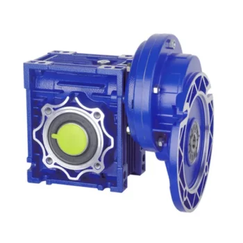
Maintenance Tips for Prolonging the Life of a Worm Gearbox
Proper maintenance is essential to ensure the longevity and reliable performance of a worm gearbox. Here are some maintenance tips to consider:
- Lubrication: Regularly check and replenish the lubricant in the gearbox. Use the recommended lubricant type and quantity specified by the manufacturer.
- Lubrication Schedule: Follow a lubrication schedule based on the operating conditions and manufacturer recommendations. Regular lubrication prevents friction, reduces wear, and dissipates heat.
- Temperature Monitoring: Keep an eye on the operating temperature of the gearbox. Excessive heat can degrade the lubricant and damage components.
- Cleanliness: Keep the gearbox and surrounding area clean from debris and contaminants. Regularly inspect and clean the gearbox exterior.
- Seal Inspection: Check for any leaks or damage to seals and gaskets. Replace them promptly to prevent lubricant leaks and contamination.
- Alignment: Ensure proper alignment between the worm and worm wheel. Misalignment can lead to increased wear and reduced efficiency.
- Torque Monitoring: Monitor the torque levels during operation. Excessive torque can cause overloading and premature wear.
- Regular Inspections: Periodically inspect all components for signs of wear, damage, or unusual noise. Replace worn or damaged parts promptly.
- Proper Usage: Operate the gearbox within its specified limits, including load, speed, and temperature. Avoid overloading or sudden changes in operating conditions.
- Expert Maintenance: If major maintenance or repairs are needed, consult the manufacturer's guidelines or seek the assistance of qualified technicians.
By following these maintenance tips and adhering to the manufacturer's recommendations, you can extend the lifespan of your worm gearbox and ensure its optimal performance over time.

Energy Efficiency of a Worm Gearbox: What to Expect
The energy efficiency of a worm gearbox is an important factor to consider when evaluating its performance. Here's what you can expect in terms of energy efficiency:
- Typical Efficiency Range: Worm gearboxes are known for their compact size and high gear reduction capabilities, but they can exhibit lower energy efficiency compared to other types of gearboxes. The efficiency of a worm gearbox typically falls in the range of 50% to 90%, depending on various factors such as design, manufacturing quality, lubrication, and load conditions.
- Inherent Losses: Worm gearboxes inherently involve sliding contact between the worm and worm wheel. This sliding contact generates friction, leading to energy losses in the form of heat. The sliding action also contributes to lower efficiency when compared to gearboxes with rolling contact.
- Helical-Worm Design: Some manufacturers offer helical-worm gearbox designs that combine elements of helical and worm gearing. These designs aim to improve efficiency by incorporating helical gears in the reduction stage, which can lead to higher efficiency compared to traditional worm gearboxes.
- Lubrication: Proper lubrication plays a significant role in minimizing friction and improving energy efficiency. Using high-quality lubricants and ensuring the gearbox is adequately lubricated can help reduce losses due to friction.
- Application Considerations: While worm gearboxes might have lower energy efficiency compared to other types of gearboxes, they still offer advantages in terms of compactness, high torque transmission, and simplicity. Therefore, the decision to use a worm gearbox should consider the specific requirements of the application, including the trade-off between energy efficiency and other performance factors.
When selecting a worm gearbox, it's essential to consider the trade-offs between energy efficiency, torque transmission, gearbox size, and the specific needs of the application. Regular maintenance, proper lubrication, and selecting a well-designed gearbox can contribute to achieving the best possible energy efficiency within the limitations of worm gearbox technology.

What is a Worm Gearbox and How Does It Work?
A worm gearbox, also known as a worm gear reducer, is a mechanical device used to transmit rotational motion and torque between non-parallel shafts. It consists of a worm screw and a worm wheel, both of which have helical teeth. The worm screw resembles a threaded cylinder, while the worm wheel is a gear with teeth that mesh with the worm screw.
The working principle of a worm gearbox involves the interaction between the worm screw and the worm wheel. When the worm screw is rotated, its helical teeth engage with the teeth of the worm wheel. As the worm screw rotates, it translates the rotational motion into a perpendicular motion, causing the worm wheel to rotate. This perpendicular motion allows the worm gearbox to achieve a high gear reduction ratio, making it suitable for applications that require significant speed reduction.
One of the key features of a worm gearbox is its ability to provide a high gear reduction ratio in a compact design. However, due to the sliding nature of the meshing teeth, worm gearboxes may exhibit higher friction and lower efficiency compared to other types of gearboxes. Therefore, they are often used in applications where efficiency is not the primary concern but where high torque and speed reduction are essential, such as conveyor systems, elevators, automotive steering systems, and certain industrial machinery.
editor by CX 2023-09-15
China high quality Tractor Rotary Mowers Bevel Cultivator Tillers Right Angle Pto Shaft Reducer Gearbox for Farm and Agricultural Machinery
Product Description
Tractor Rotary Mowers Bevel Fertilizer Spreader Tillers Right Angle Pto Shaft Reducer Gearbox for Farm and Agricultural Machinery
Established in Nov.2002,HangZhou CHINAMFG is a professional manufacturer and supplier in supplying spare parts and accessories for agricultural machinery. In addition to the 3000 standards parts, we also offer our customers tailor-made articles or assemblies that are for special application.
HangZhou CHINAMFG focused on the development and production of gearboxes with a professional team and continue to learn advanced technology; the use of first-class equipment; high quality supply chain system, relying on these, the gearboxes get high reputation among customers at home and abroad.
These gearboxes are widely used in rotary tillers, lawn mowers, harvesters, hole diggers, pesticide sprayers, irrigation machines, fertilizer spreaders, blenders and so on. The main products are:
--Straight bevel gearbox
--Spiral bevel gearbox
--Planetary reducer
--Worm gearbox
HangZhou CHINAMFG International Trading Co.,Ltd is a modern enterprise specilizing in the development, production, sales and services of PTO shaft. We adhere to the principle of "Precise Driveline, Advocate Green", using advanced technology and equipments to ensure all the technical standards of precise driveline. So that the transmission efficiency can be maxmized and every drop of resource of customers' can be saved. Meanwhile, we have a customer-centric service system, providing a full range of pre-sale, sale and after-sale service. Customer satisfaction is our forever pursuit.
We follow the principle of people first, trying our best to set up a pleasant surroundings and platform of performance for each employee, so everyone can be self-consciously active to join in "Precise Driveline, Adocate Green" to embody the self-worth, enterprise value and social value.
Newnuro's goal is: reducing customer's purchase budget, support customers to earn more market.
Newnuro always finds solution for customers.Customer satisfaction is our ultimate goal and forever pursuit.
| Application: | Machinery, Agricultural Machinery |
|---|---|
| Function: | Distribution Power, Change Drive Torque, Change Drive Direction, Speed Changing, Speed Reduction, Speed Increase |
| Layout: | Assembled |
| Hardness: | Hardened Tooth Surface |
| Installation: | Horizontal Type |
| Step: | Single-Step |
| Samples: |
US$ 50/Piece
1 Piece(Min.Order) | |
|---|
| Customization: |
Available
| Customized Request |
|---|

How do PTO shafts handle variations in length and connection methods?
PTO (Power Take-Off) shafts are designed to handle variations in length and connection methods to accommodate different equipment setups and ensure efficient power transfer. PTO shafts need to be adjustable in length to bridge the distance between the power source and the driven machinery. Additionally, they must provide versatile connection methods to connect to a wide range of equipment. Here's a detailed explanation of how PTO shafts handle variations in length and connection methods:
1. Telescoping Design: PTO shafts often feature a telescoping design, allowing them to be adjusted in length to suit different equipment configurations. The telescoping feature enables the shaft to extend or retract, accommodating varying distances between the power source (such as a tractor or engine) and the driven machinery. By adjusting the length of the PTO shaft, it can be properly aligned and connected to ensure optimal power transfer. Telescoping PTO shafts typically consist of multiple tubular sections that slide into one another, providing flexibility in length adjustment.
2. Splined Shafts: PTO shafts commonly employ splined shafts as the primary connection method between the power source and driven machinery. Splines are a series of ridges or grooves along the shaft that interlock with corresponding grooves in the mating component. The splined connection allows for torque transfer while maintaining alignment between the power source and driven machinery. Splined shafts can handle variations in length by extending or retracting the telescoping sections while still maintaining a solid connection between the power source and the driven equipment.
3. Adjustable Sliding Yokes: PTO shafts typically feature adjustable sliding yokes on one or both ends of the shaft. These yokes allow for angular adjustment, accommodating variations in the alignment between the power source and driven machinery. The sliding yokes can be moved along the splined shaft to achieve the desired angle and maintain proper alignment. This flexibility ensures that the PTO shaft can handle length variations while ensuring efficient power transfer without placing excessive strain on the universal joints or other components.
4. Universal Joints: Universal joints are integral components of PTO shafts that allow for angular misalignment between the power source and driven machinery. They consist of a cross-shaped yoke with bearings that transmit torque between connected shafts while accommodating misalignment. Universal joints provide flexibility in connecting PTO shafts to equipment that may not be perfectly aligned. As the PTO shaft length varies, the universal joints compensate for the changes in angle, allowing for smooth power transmission even when there are variations in length or misalignment between the power source and driven machinery.
5. Coupling Mechanisms: PTO shafts utilize various coupling mechanisms to securely connect to the power source and driven machinery. These mechanisms often involve a combination of splines, bolts, locking pins, or quick-release mechanisms. The coupling methods can vary depending on the specific equipment and industry requirements. The versatility of PTO shafts allows for the use of different coupling methods, ensuring a reliable and secure connection regardless of the length variation or equipment configuration.
6. Customization Options: PTO shafts can be customized to handle specific length variations and connection methods. Manufacturers offer options to select different lengths of telescoping sections to match the specific distance between the power source and driven machinery. Additionally, PTO shafts can be tailored to accommodate various connection methods through the selection of splined shaft sizes, yoke designs, and coupling mechanisms. This customization enables PTO shafts to meet the specific requirements of different equipment setups, ensuring optimal power transfer and compatibility.
7. Safety Considerations: When handling variations in length and connection methods, it is essential to consider safety. PTO shafts incorporate protective guards and shields to prevent accidental contact with rotating components. These safety measures must be appropriately adjusted and installed to provide adequate coverage and protection, regardless of the PTO shaft's length or connection configuration. Safety guidelines and regulations should be followed to ensure the proper installation, adjustment, and use of PTO shafts in order to prevent accidents or injuries.
By incorporating telescoping designs, splined shafts, adjustable sliding yokes, universal joints, and versatile coupling mechanisms, PTO shafts can handle variations in length and connection methods. The flexibility of PTO shafts allows them to adapt to different equipment setups, ensuring efficient power transfer while maintaining alignment and safety.

How do PTO shafts contribute to the efficiency of agricultural operations?
Power Take-Off (PTO) shafts play a crucial role in improving the efficiency of agricultural operations by providing a versatile and reliable power source for various farming equipment. PTO shafts allow agricultural machinery to access power from tractors or other prime movers, enabling the efficient transfer of energy to perform a wide range of tasks. Here's a detailed explanation of how PTO shafts contribute to the efficiency of agricultural operations:
1. Versatility: PTO shafts offer versatility by allowing the connection of different types of implements and machinery to tractors or other power sources. This versatility enables farmers to use a single power unit, such as a tractor, to operate multiple agricultural implements, including mowers, balers, tillers, seeders, sprayers, and more. The ability to quickly switch between various implements using a PTO shaft minimizes downtime and maximizes efficiency in agricultural operations.
2. Power Transfer: PTO shafts efficiently transfer power from the tractor's engine to the agricultural implements. The rotating power generated by the engine is transmitted through the PTO shaft to drive the machinery connected to it. This direct power transfer eliminates the need for separate engines or motors on each implement, reducing equipment costs and maintenance requirements. PTO shafts ensure a reliable power supply, allowing agricultural operations to be carried out efficiently and effectively.
3. Increased Productivity: By utilizing PTO shafts, agricultural operations can be performed more quickly and efficiently than manual or alternative power methods. PTO-driven machinery typically operates at higher speeds and with greater power compared to human-operated or manual tools. This increased productivity allows farmers to complete tasks such as tilling, seeding, harvesting, and material handling more efficiently, reducing labor requirements and increasing overall farm productivity.
4. Time Savings: PTO shafts contribute to time savings in agricultural operations. The ability to connect and disconnect implements quickly using standardized PTO shafts allows farmers to switch between tasks rapidly. This saves time during equipment setup, as well as when transitioning between different operations in the field. Time efficiency is particularly valuable during critical farming periods, such as planting or harvesting, where timely execution is essential for optimal crop yield and quality.
5. Reduced Manual Labor: PTO shafts minimize the need for manual labor in strenuous or repetitive tasks. By harnessing the power of tractors or other prime movers, farmers can mechanize various operations that would otherwise require significant physical effort. Agricultural implements driven by PTO shafts can perform tasks such as plowing, mowing, and baling with minimal human intervention, reducing labor costs and improving overall efficiency.
6. Precision and Consistency: PTO shafts contribute to precision and consistency in agricultural operations. The consistent power supply from the PTO ensures uniform operation and performance of the connected machinery. This helps in achieving consistent seed placement, even spreading of fertilizers or chemicals, and precise cutting or harvesting of crops. Precision and consistency lead to improved crop quality, enhanced yield, and reduced waste, ultimately contributing to the overall efficiency of agricultural operations.
7. Adaptability to Various Terrain: PTO-driven machinery is highly adaptable to various types of terrain encountered in agricultural operations. Tractors equipped with PTO shafts can traverse uneven or challenging terrain, allowing implements to operate effectively on slopes, rough fields, or hilly landscapes. This adaptability ensures that farmers can efficiently manage their land, regardless of topographical challenges, enhancing operational efficiency and productivity.
8. Integration with Automation and Technology: PTO shafts can be integrated with automation and technology advancements in modern agricultural practices. Automation systems, such as precision guidance and control, can be synchronized with PTO-driven machinery to optimize operations and minimize waste. Additionally, advancements in data collection and analysis allow farmers to monitor and optimize machine performance, fuel efficiency, and productivity, further enhancing the efficiency of agricultural operations.
By providing versatility, efficient power transfer, increased productivity, time savings, reduced manual labor, precision, adaptability to terrain, and integration with automation and technology, PTO shafts significantly contribute to enhancing the efficiency of agricultural operations. They enable farmers to perform a wide range of tasks with ease, ultimately improving productivity, reducing costs, and supporting sustainable farming practices.

Which industries commonly use PTO shafts for power transmission?
PTO shafts (Power Take-Off shafts) are widely used in various industries where power transmission is required to drive machinery and equipment. Their versatility, efficiency, and compatibility with different types of machinery make them valuable components in several sectors. Here's a detailed explanation of the industries that commonly use PTO shafts for power transmission:
1. Agriculture: The agricultural industry extensively relies on PTO shafts for power transmission. Tractors equipped with PTOs are commonly used to drive a wide range of agricultural implements and machinery. PTO-driven equipment includes mowers, balers, tillers, seeders, sprayers, grain augers, harvesters, and many more. PTO shafts allow for the efficient transfer of power from the tractor's engine to these implements, enabling various agricultural operations such as cutting, baling, tilling, planting, spraying, and harvesting. The agricultural sector heavily depends on PTO shafts to enhance productivity and streamline farming processes.
2. Construction and Earthmoving: In the construction and earthmoving industry, PTO shafts find applications in machinery used for excavation, grading, and material handling. PTO-driven equipment such as backhoes, loaders, excavators, trenchers, and stump grinders utilize PTO shafts to transfer power from the prime movers, typically hydraulic systems, to drive the necessary attachments. These attachments require the high torque and power provided by PTO shafts to perform tasks like digging, loading, trenching, and grinding. PTO shafts allow for versatile and efficient power transmission in construction and earthmoving operations.
3. Forestry: The forestry industry utilizes PTO shafts for power transmission in various logging and timber processing equipment. PTO-driven machinery such as wood chippers, sawmills, log splitters, and debarkers rely on PTO shafts to transfer power from tractors or dedicated power units to perform tasks like chipping, sawing, splitting, and debarking wood. PTO shafts provide the necessary power and torque to drive the cutting and processing mechanisms, enabling efficient and productive forestry operations.
4. Landscaping and Groundskeeping: PTO shafts play a crucial role in the landscaping and groundskeeping industry. Equipment like lawn mowers, rotary cutters, flail mowers, and aerators utilize PTO shafts to transfer power from tractors or dedicated power units to drive the cutting or grooming mechanisms. PTO shafts enable efficient power transmission, allowing operators to maintain lawns, parks, golf courses, and other outdoor spaces with precision and productivity.
5. Mining and Quarrying: PTO shafts have applications in the mining and quarrying industry, particularly in equipment used for material extraction, crushing, and screening. PTO-driven machinery such as crushers, screeners, and conveyors rely on PTO shafts to transfer power from engines or motors to drive the crushing and screening mechanisms, as well as the material handling systems. PTO shafts provide the necessary power and torque to process and transport bulk materials effectively in mining and quarrying operations.
6. Industrial Manufacturing: PTO shafts are utilized in various industrial manufacturing processes that require power transmission to drive specific machinery and equipment. Industries such as food processing, textile manufacturing, paper production, and chemical processing may use PTO-driven machinery for tasks like mixing, blending, cutting, extruding, and conveying. PTO shafts enable efficient power transfer to these machines, ensuring smooth and reliable operation in industrial manufacturing settings.
7. Utilities and Infrastructure Maintenance: PTO shafts find applications in utilities and infrastructure maintenance operations. Equipment like street sweepers, sewer cleaners, road maintenance machines, and drain augers utilize PTO shafts to transfer power from trucks or dedicated power units to perform tasks like sweeping, cleaning, and maintenance of roads, sewers, and other public infrastructure. PTO shafts enable efficient power transmission, ensuring effective and reliable operation of these utility and maintenance machines.
8. Others: PTO shafts are also used in several other industries and sectors where power transmission is required. This includes applications in the transportation industry for powering refrigeration units, fuel pumps, and hydraulic systems in trucks and trailers. PTO shafts also find applications in the marine industry for powering winches, pumps, and other equipment on boats and ships.
In summary, PTO shafts are commonly used in a wide range of industries for power transmission. These industries include agriculture, construction and earthmoving, forestry, landscaping and groundskeeping, mining and quarrying, industrial manufacturing, utilities and infrastructure maintenance, transportation, and marine sectors. PTO shafts play a critical rolein enhancing productivity, enabling efficient operation of machinery, and facilitating various tasks in these industries.

editor by CX 2023-09-15