Product Description
Hoist Lift Winch Crane Pushing Pulling Pressing Mixing Moving Helical Worm Right Angle Gear Speed Reducer
Product Description
1. Compact structure and simple assembly;
2. Wide speed ranges and high torque;
3. Low noise, good sealing performance, high efficiency;
4. Stable and safe, long lifetime, universal;
5. Multi-structure, various assembling methods
Detailed Photos
Related Product
Product Parameters
| ANG Helical Gear Reducer | |
| Model | R17 ~ 187, F37-177, K37-187, S37-97 |
| Input power | 0.06kw ~ 250kw |
| Input speed | 750rpm ~ 3000rpm |
| Reduction ratio | 1/1.3 ~ 1/27000 |
| Input motor | AC (1 phase or 3 phase) / DC / BLDC motor |
| Install type | Foot / CHINAMFG shaft / Hollow shaft / Output flange… |
| Efficiency | 94% ~ 98 % for R F K series |
| Material of housing | die-cast aluminum / Cast iron / Stainless steel |
| Precision of gear | Accurate grinding, class 6 |
| Heat treatment | Carburizing and quenching |
| Accessories | Brake / Flange / Motor adapter / Torque arm … |
Our Advantages
Company Profile
Certifications
FAQ
Q: Can you make the gear reducer with customization?
A: Yes, we can customize per your request, like oil, bearing, shaft size, flange, etc.
Q: Do you provide samples?
A: Yes. The sample is available for testing.
Q: What's your lead time?
A: Standard products need 5-30 days, a bit longer for customized products.
Q: Do you provide technical support?
A: Yes. Our company has a design and development team, we can provide technical support if you
need.
Q: How to ship to us?
A: It is available by air, by sea, or by train.
Q: How to pay the money?
A: T/T and L/C are preferred, with different currencies, including USD, EUR, RMB, etc.
Q: How can I know if the product is suitable for me?
A: >1ST confirm drawing and specification >2nd test sample >3rd start mass production.
Q: Can I come to your company to visit?
A: Yes, you are welcome to visit us at any time.
Q: How shall we contact you?
A: You can send an inquiry directly, and we will respond within 24 hours. /* January 22, 2571 19:08:37 */!function(){function s(e,r){var a,o={};try{e&&e.split(",").forEach(function(e,t){e&&(a=e.match(/(.*?):(.*)$/))&&1
| Application: | Motor, Machinery, Marine, Agricultural Machinery, Car |
|---|---|
| Hardness: | Hardened Tooth Surface |
| Installation: | 90 Degree |
| Samples: |
US$ 300/Piece
1 Piece(Min.Order) | Order Sample Blue or Grey
|
|---|
| Customization: |
Available
| Customized Request |
|---|
.shipping-cost-tm .tm-status-off{background: none;padding:0;color: #1470cc}
|
Shipping Cost:
Estimated freight per unit. |
about shipping cost and estimated delivery time. |
|---|
| Payment Method: |
|
|---|---|
|
Initial Payment Full Payment |
| Currency: | US$ |
|---|
| Return&refunds: | You can apply for a refund up to 30 days after receipt of the products. |
|---|

Can gear reducers be customized for specific industrial needs and requirements?
Yes, gear reducers can be customized to meet specific industrial needs and requirements. Manufacturers offer customization options to ensure that gear reducers are tailored to the unique demands of various applications:
1. Gear Ratio Selection: Gear reducers can be designed with specific gear ratios to achieve the desired speed reduction or increase, catering to the specific requirements of the machinery or equipment.
2. Shaft Configurations: Gear reducers can be configured with different shaft sizes, lengths, and orientations to fit seamlessly into existing systems or accommodate specific mounting arrangements.
3. Torque Capacity: Customized gear reducers can be designed to handle higher or lower torque loads based on the application's operational requirements.
4. Environmental Considerations: Gear reducers can be customized with special coatings, materials, or seals to withstand harsh environments, extreme temperatures, or corrosive conditions.
5. Noise and Vibration Reduction: Custom designs can incorporate features to reduce noise and dampen vibrations, enhancing the overall operation and user experience.
6. Mounting and Connection Options: Manufacturers can adapt gear reducer designs to include specific mounting interfaces or connection methods that align with the equipment's design.
7. Lubrication and Maintenance: Customized gear reducers can include features for easy maintenance, such as accessible lubrication points or monitoring systems.
8. Integration with Controls: Gear reducers can be customized to integrate seamlessly with control systems, sensors, or automation processes, enhancing system efficiency and performance.
By collaborating with manufacturers and providing detailed specifications, industries can obtain tailor-made gear reducers that address their specific operational needs and contribute to the success of their applications.

What maintenance practices are essential for prolonging the lifespan of gear reducers?
Proper maintenance is crucial for extending the lifespan and ensuring optimal performance of gear reducers. Here are essential maintenance practices:
- 1. Lubrication: Regular lubrication of gear reducers is vital to reduce friction, wear, and heat generation. Use the recommended lubricant and follow the manufacturer's guidelines for lubrication intervals.
- 2. Inspection: Routinely inspect gear reducers for signs of wear, damage, or leaks. Check for unusual noises, vibrations, or temperature increases during operation.
- 3. Alignment: Ensure proper alignment of the input and output shafts. Misalignment can lead to increased wear, noise, and reduced efficiency. Align the components according to the manufacturer's specifications.
- 4. Cooling and Ventilation: Maintain proper cooling and ventilation to prevent overheating. Ensure that cooling fans and vents are clean and unobstructed.
- 5. Seal Maintenance: Inspect and replace seals as needed to prevent contaminants from entering the gear reducer. Contaminants can lead to accelerated wear and reduced performance.
- 6. Bolts and Fasteners: Regularly check and tighten bolts and fasteners to prevent loosening during operation, which can cause misalignment or component damage.
- 7. Replacing Worn Components: Replace worn or damaged components, such as gears, bearings, and seals, with genuine parts from the manufacturer.
- 8. Vibration Analysis: Conduct periodic vibration analysis to identify potential issues early. Excessive vibration can indicate misalignment or component wear.
- 9. Maintenance Records: Keep detailed maintenance records, including lubrication schedules, inspection dates, and component replacements. This helps track the history of the gear reducer and aids in future maintenance planning.
- 10. Training: Provide proper training to maintenance personnel on gear reducer maintenance and troubleshooting techniques.
By adhering to these maintenance practices, you can maximize the lifespan of your gear reducers, minimize downtime, and ensure reliable operation in your industrial processes.

Are there variations in gear reducer designs for specific tasks and applications?
Yes, gear reducer designs vary widely to suit specific tasks and applications across various industries. Manufacturers offer a range of gear reducer types and configurations to accommodate different requirements, including:
- Helical Gear Reducers: These are versatile and provide smooth and efficient torque transmission. They are commonly used in applications requiring high precision and moderate speed reduction, such as conveyors, mixers, and agitators.
- Bevel Gear Reducers: These are ideal for transmitting power between intersecting shafts. They are often used in heavy machinery, printing presses, and automotive applications.
- Worm Gear Reducers: These provide compact solutions and are suitable for applications with higher speed reduction requirements, such as conveyor systems, winches, and elevators.
- Planetary Gear Reducers: These offer high torque density and are used in applications demanding precise control, such as robotics, aerospace, and heavy-duty machinery.
- Parallel Shaft Gear Reducers: Commonly used in industrial machinery, these reducers are designed for high torque and reliability.
- Right-Angle Gear Reducers: These are used when space limitations require a change in shaft direction, commonly found in packaging equipment and conveyors.
Each type of gear reducer has unique features and benefits that make it suitable for specific tasks. Manufacturers often provide customization options to tailor gear reducers to the precise requirements of an application, including gear ratios, mounting options, and input/output configurations.
Therefore, the variation in gear reducer designs allows industries to select the most appropriate type based on factors such as torque, speed, space constraints, precision, and environmental conditions.


editor by CX 2024-03-29
China Best Sales Commutator Right Angle Reducer Spiral Bevel Gear Shaft Hole Output with Servo gearbox adjustment
Product Description
Packaging & Shipping
LANETX planetary reducer
Commutator right angle reducer spiral bevel gear shaft hole output with servo
product-list-1.html
Product parameters
| Model | Unit | AT042A | AT060A | AT085A | AT110A | Ratios | Steges |
| Rated output torque | Nm | 19.0 | 50.0 | 160.0 | 1 | 1-stages | |
| 4.5 | 25.0 | 60.0 | 140.0 | 2 | |||
| 6.0 | 16.5 | 60.0 | 3 | ||||
| 4.0 | 12.0 | 40.0 | 5 | ||||
| 4.7 | 26.0 | 60.0 | 140.0 | 6 | 2-stages | ||
| 4.9 | 27.0 | 63.0 | 148.0 | 8 | |||
| 5.1 | 28.0 | 66.0 | 155.0 | 10 | |||
| 5.3 | 29.0 | 68.0 | 160.0 | 14 | |||
| 5.5 | 30.0 | 72.0 | 165.0 | 20 | |||
| Fault stop torque | Nm | 32*Nominal torqute | |||||
| Backlash | arcmin | ≤2 | ≤2 | ≤2 | ≤3 | P1 | 1-stages |
| ≤6 | ≤6 | ≤6 | ≤7 | P2 | |||
| ≤5 | ≤5 | ≤5 | ≤6 | P1 | 2-stages | ||
| ≤12 | ≤12 | ≤12 | ≤14 | P2 | |||
| Rated input speed | rpm | 3000 | 3000 | 3000 | 2500 | ||
| Maximum input speed | rpm | 6000 | 6000 | 6000 | 5000 | ||
| Noise | dB | ≤60 | ≤62 | ≤65 | ≤68 | ||
| Backlash | arcmin | <2 | <2 | <2 | <2 | P1 | 1-stages |
| <6 | <6 | <6 | <6 | P2 | |||
| <5 | <5 | <5 | <5 | P1 | 2-stages | ||
| <12 | <12 | <12 | <12 | P2 |
- How do we know the product quality?
A1.We suggest you order samples. In addition, you can send an email to us for detailed photos to check if you can't get enough information in the product page
2.Is this your final price? Can I have a discount?A2.Our price is ex factory.
A2.If you want a large quantity, we can give you a discount
3.Can we visit your factory?
A3.Yes, a warm welcome. Floor 3, Building 1, No. 12, Xihu (West Lake) Dis. Road, Wanjiang District, HangZhou City, Guangd
Essential details
Warranty:1 year, 1 Year
Applicable Industries:Building Material Shops, Manufacturing Plant, Machinery Repair Shops, Retail, Construction works , packaging machine, automation line, equipment
Weight (KG):5
Customized support:OEM, ODM, OBM
Place of Origin:Xihu (West Lake) Dis. guan, China
Brand Name:SAIYA
Gearing Arrangement:
Output Torque:16.5-720 N.M
Input Speed:3000
Output Speed:4200RPM-7000RPM
Product name:Planetary Gearbox
Color:Silver and gold
Quality:High Level
Usage:Industrial Robot
Brand:PLANETX
Material:Metal
Noise:≤58-≤65
Lifetimes:20000h
Minimum operating temperature:-25ºC
Maximum operating temperature:+90ºC
Degree of protection:IP65
Lubrication method:Long term lubrication
Installation method:Any
Q: How to get a quick quote
A: Please provide the following information when contacting us
- Motor brand
- Motor model
- Motor dimension drawing
- What is the gear ratio
Q: How long is your delivery date
A: We all install it now, but it takes 3-5 days if it is not non-standard. Non standard 10-15 days, depending on the specific situation
Q:Do you provide samples, free or extra
A: A: You can reserve 1 first, and purchase it on demand
/* March 10, 2571 17:59:20 */!function(){function s(e,r){var a,o={};try{e&&e.split(",").forEach(function(e,t){e&&(a=e.match(/(.*?):(.*)$/))&&1
| Application: | Machinery |
|---|---|
| Hardness: | Hardened Tooth Surface |
| Installation: | Any |
| Layout: | Coaxial |
| Gear Shape: | Cylindrical Gear |
| Step: | One |
| Customization: |
Available
| Customized Request |
|---|

Are there any disadvantages or limitations to using gear reducer systems?
While gear reducer systems offer numerous advantages, they also come with certain disadvantages and limitations that should be considered during the selection and implementation process:
1. Size and Weight: Gear reducers can be bulky and heavy, especially for applications requiring high gear ratios. This can impact the overall size and weight of the machinery or equipment, which may be a concern in space-constrained environments.
2. Efficiency Loss: Despite their high efficiency, gear reducers can experience energy losses due to friction between gear teeth and other components. This can lead to a reduction in overall system efficiency, particularly in cases where multiple gear stages are used.
3. Cost: The design, manufacturing, and assembly of gear reducers can involve complex processes and precision machining, which can contribute to higher initial costs compared to other power transmission solutions.
4. Maintenance: Gear reducer systems require regular maintenance, including lubrication, inspection, and potential gear replacement over time. Maintenance activities can lead to downtime and associated costs in industrial settings.
5. Noise and Vibration: Gear reducers can generate noise and vibrations, especially at high speeds or when operating under heavy loads. Additional measures may be needed to mitigate noise and vibration issues.
6. Limited Gear Ratios: While gear reducers offer a wide range of gear ratios, there may be limitations in achieving extremely high or low ratios in certain designs.
7. Temperature Sensitivity: Extreme temperatures can affect the performance of gear reducer systems, particularly if inadequate lubrication or cooling is provided.
8. Shock Loads: While gear reducers are designed to handle shock loads to some extent, severe shock loads or abrupt changes in torque can still lead to potential damage or premature wear.
Despite these limitations, gear reducer systems remain widely used and versatile components in various industries, and their disadvantages can often be mitigated through proper design, selection, and maintenance practices.

How do gear reducers handle shock loads and sudden changes in torque?
Gear reducers are designed to handle shock loads and sudden changes in torque through several mechanisms that enhance their durability and reliability in challenging operating conditions.
1. Robust Construction: Gear reducers are constructed using high-strength materials and precision manufacturing techniques. This ensures that the gears, bearings, and other components can withstand sudden impacts and high torque fluctuations without deformation or failure.
2. Shock-Absorbing Features: Some gear reducer designs incorporate shock-absorbing features, such as flexible couplings, elastomeric elements, or torsionally flexible gear designs. These features help dampen and dissipate the energy from sudden shocks or torque spikes, reducing the impact on the entire system.
3. Torque Limiters: In applications where shock loads are common, torque limiters may be integrated into the gear reducer. These devices automatically disengage or slip when a certain torque threshold is exceeded, preventing damage to the gears and other components.
4. Overload Protection: Gear reducers can be equipped with overload protection mechanisms, such as shear pins or torque sensors. These mechanisms detect excessive torque and disengage the drive temporarily, allowing the system to absorb the shock or adjust to the sudden torque change.
5. Proper Lubrication: Adequate lubrication is essential for managing shock loads and sudden torque changes. High-quality lubricants reduce friction and wear, helping the gear reducer withstand dynamic forces and maintain smooth operation.
6. Dynamic Load Distribution: Gear reducers distribute dynamic loads across multiple gear teeth, which helps prevent localized stress concentrations. This feature minimizes the risk of tooth breakage and gear damage when subjected to sudden changes in torque.
By incorporating these design features and mechanisms, gear reducers can effectively handle shock loads and sudden changes in torque, ensuring the longevity and reliability of various industrial and mechanical systems.

How do gear reducers handle variations in input and output speeds?
Gear reducers are designed to handle variations in input and output speeds through the use of different gear ratios and configurations. They achieve this by utilizing intermeshing gears of varying sizes to transmit torque and control rotational speed.
The basic principle involves connecting two or more gears with different numbers of teeth. When a larger gear (driving gear) engages with a smaller gear (driven gear), the rotational speed of the driven gear decreases while the torque increases. This reduction in speed and increase in torque enable gear reducers to efficiently adapt to variations in input and output speeds.
The gear ratio is a critical factor in determining how much the speed and torque change. It is calculated by dividing the number of teeth on the driven gear by the number of teeth on the driving gear. A higher gear ratio results in a greater reduction in speed and a proportionate increase in torque.
Planetary gear reducers, a common type, use a combination of gears including sun gears, planet gears, and ring gears to achieve different speed reductions and torque enhancements. This design provides versatility in handling variations in speed and torque requirements.
In summary, gear reducers handle variations in input and output speeds by using specific gear ratios and gear arrangements that enable them to efficiently transmit power and control motion characteristics according to the application's needs.
editor by CX 2024-02-09
China best 2022 Hotsales Zero Backlash 90° Right Angle Planetary Gear Reducer synchromesh gearbox
Product Description
2571 Hotsales Zero Backlash 90° Right Angle Planetary Gear Reducer
Newgear brand Precision Planetary reducer gearbox for Industrial Robot and Automatic Arm
This Spur planetary gearbox is used for servo motor and related device which need to reduce speed or enlarge torque! CHINAMFG Spur planetary gearboxes external diameter from 60 to 160, gear ratio from 3 to 100! It has high precision and are widely used with servo motor such like Panasonnic,Fuji, Mitsubishi, Omran,Delta, Teco.
Product Description
Characteristic:
(1) Low Noise:The use of helical gear design,to achieve a smooth,quite operation of the reducer.
(2) High Precision:Backlash is 3 arcmin or less,accurate positioning.
(3) High Rigidity,High Torque:The output shaft used large size,large span double support bearing design,which improves the rigidity and torque of the reducer.
(4) High Efficiency:1-stage up to 95% or more,2-stage up to 92% or more.
(5) Maintenance-Free:Low grease wear,can be lifetime lubrication.
(6) Sealing Effect is Good:Lubricating grease with high viscosity,not easy to separate the characteristics,ip65 protection class to ensure that no grease leakage.
(7) Installation Unrestrained:Can be installed arbitrarily.
(8) Wide Applicability:Applicable to any type of servo motor.
(9) An organic [integral] whole output axis.
| Specifications | PVFN60 | PVFN90 | PVFN120 | |||
| Technal Parameters | ||||||
| Max. Torque | Nm | 1.5times rated torque | ||||
| Emergency Stop Torque | Nm | 2.5times rated torque | ||||
| Max. Radial Load | N | 240 | 450 | 1240 | ||
| Max. Axial Load | N | 220 | 430 | 1000 | ||
| Torsional Rigidity | Nm/arcmin | 1.8 | 4.85 | 11 | ||
| Max.Input Speed | rpm | 8000 | 6000 | 6000 | ||
| Rated Input Speed | rpm | 4000 | 3500 | 3500 | ||
| Noise | dB | ≤58 | ≤60 | ≤65 | ||
| Average Life Time | h | 20000 | ||||
| Efficiency Of Full Load | % | L1≥95% L2≥92% | ||||
| Return Backlash | P1 | L1 | arcmin | ≤8 | ≤8 | ≤8 |
| L2 | arcmin | ≤12 | ≤12 | ≤12 | ||
| P2 | L1 | arcmin | ≤16 | ≤16 | ≤16 | |
| L2 | arcmin | ≤20 | ≤20 | ≤20 | ||
| Moment Of Inertia Table | L1 | 3 | Kg*cm2 | 0.46 | 1.73 | 12.78 |
| 4 | Kg*cm2 | 0.46 | 1.73 | 12.78 | ||
| 5 | Kg*cm2 | 0.46 | 1.73 | 12.78 | ||
| 7 | Kg*cm2 | 0.41 | 1.42 | 11.38 | ||
| 10 | Kg*cm2 | 0.41 | 1.42 | 11.38 | ||
| L2 | 12 | Kg*cm2 | 0.44 | 1.49 | 12.18 | |
| 15 | Kg*cm2 | 0.44 | 1.49 | 12.18 | ||
| 16 | Kg*cm2 | 0.72 | 1.49 | 12.18 | ||
| 20 | Kg*cm2 | 0.44 | 1.49 | 12.18 | ||
| 25 | Kg*cm2 | 0.44 | 1.49 | 12.18 | ||
| 28 | Kg*cm2 | 0.44 | 1.49 | 12.18 | ||
| 30 | Kg*cm2 | 0.44 | 1.49 | 12.18 | ||
| 35 | Kg*cm2 | 0.44 | 1.49 | 12.18 | ||
| 40 | Kg*cm2 | 0.44 | 1.49 | 12.18 | ||
| 50 | Kg*cm2 | 0.34 | 1.25 | 11.48 | ||
| 70 | Kg*cm2 | 0.34 | 1.25 | 11.48 | ||
| 100 | Kg*cm2 | 0.34 | 1.25 | 11.48 | ||
| Technical Parameter | Level | Ratio | PVFN60 | PVFN90 | PVFN120 | |
| Rated Torque | L1 | 3 | Nm | 27 | 96 | 161 |
| 4 | Nm | 40 | 122 | 210 | ||
| 5 | Nm | 40 | 122 | 210 | ||
| 7 | Nm | 34 | 95 | 170 | ||
| 10 | Nm | 16 | 56 | 86 | ||
| L2 | 12 | Nm | 27 | 96 | 161 | |
| 15 | Nm | 27 | 96 | 161 | ||
| 16 | Nm | 40 | 122 | 210 | ||
| 20 | Nm | 40 | 122 | 210 | ||
| 25 | Nm | 40 | 122 | 210 | ||
| 28 | Nm | 40 | 122 | 210 | ||
| 30 | Nm | 27 | 96 | 161 | ||
| 35 | Nm | 40 | 122 | 210 | ||
| 40 | Nm | 40 | 122 | 210 | ||
| 50 | Nm | 40 | 122 | 210 | ||
| 70 | Nm | 34 | 95 | 170 | ||
| 100 | Nm | 16 | 56 | 86 | ||
| Degree Of Protection | IP65 | |||||
| Operation Temprature | ºC | - 10ºC to -90ºC | ||||
| Weight | L1 | kg | 1.7 | 4.4 | 12 | |
| L2 | kg | 1.9 | 5 | 14 | ||
Company Profile
Packaging & Shipping
Quality inspection procedure:
We have 20 QC/QA workers.10 strict QC processes including incoming materials QC, IPQC 10 Ageing test QC100% products will go through a 24-hours ageing test QC)before shipping.
/* March 10, 2571 17:59:20 */!function(){function s(e,r){var a,o={};try{e&&e.split(",").forEach(function(e,t){e&&(a=e.match(/(.*?):(.*)$/))&&1
| Application: | Motor, Electric Cars, Machinery, Marine, Agricultural Machinery, Car, Textile Machinery |
|---|---|
| Hardness: | Hardened Tooth Surface |
| Installation: | Horizontal Type |
| Samples: |
US$ 120/Set
1 Set(Min.Order) | Order Sample |
|---|
| Customization: |
Available
| Customized Request |
|---|
.shipping-cost-tm .tm-status-off{background: none;padding:0;color: #1470cc}
| Shipping Cost:
Estimated freight per unit. |
about shipping cost and estimated delivery time. |
|---|
| Payment Method: |
|
|---|---|
|
Initial Payment Full Payment |
| Currency: | US$ |
|---|
| Return&refunds: | You can apply for a refund up to 30 days after receipt of the products. |
|---|
Can gear reducers be customized for specific industrial needs and requirements?
Yes, gear reducers can be customized to meet specific industrial needs and requirements. Manufacturers offer customization options to ensure that gear reducers are tailored to the unique demands of various applications:
1. Gear Ratio Selection: Gear reducers can be designed with specific gear ratios to achieve the desired speed reduction or increase, catering to the specific requirements of the machinery or equipment.
2. Shaft Configurations: Gear reducers can be configured with different shaft sizes, lengths, and orientations to fit seamlessly into existing systems or accommodate specific mounting arrangements.
3. Torque Capacity: Customized gear reducers can be designed to handle higher or lower torque loads based on the application's operational requirements.
4. Environmental Considerations: Gear reducers can be customized with special coatings, materials, or seals to withstand harsh environments, extreme temperatures, or corrosive conditions.
5. Noise and Vibration Reduction: Custom designs can incorporate features to reduce noise and dampen vibrations, enhancing the overall operation and user experience.
6. Mounting and Connection Options: Manufacturers can adapt gear reducer designs to include specific mounting interfaces or connection methods that align with the equipment's design.
7. Lubrication and Maintenance: Customized gear reducers can include features for easy maintenance, such as accessible lubrication points or monitoring systems.
8. Integration with Controls: Gear reducers can be customized to integrate seamlessly with control systems, sensors, or automation processes, enhancing system efficiency and performance.
By collaborating with manufacturers and providing detailed specifications, industries can obtain tailor-made gear reducers that address their specific operational needs and contribute to the success of their applications.
How do gear reducers handle shock loads and sudden changes in torque?
Gear reducers are designed to handle shock loads and sudden changes in torque through several mechanisms that enhance their durability and reliability in challenging operating conditions.
1. Robust Construction: Gear reducers are constructed using high-strength materials and precision manufacturing techniques. This ensures that the gears, bearings, and other components can withstand sudden impacts and high torque fluctuations without deformation or failure.
2. Shock-Absorbing Features: Some gear reducer designs incorporate shock-absorbing features, such as flexible couplings, elastomeric elements, or torsionally flexible gear designs. These features help dampen and dissipate the energy from sudden shocks or torque spikes, reducing the impact on the entire system.
3. Torque Limiters: In applications where shock loads are common, torque limiters may be integrated into the gear reducer. These devices automatically disengage or slip when a certain torque threshold is exceeded, preventing damage to the gears and other components.
4. Overload Protection: Gear reducers can be equipped with overload protection mechanisms, such as shear pins or torque sensors. These mechanisms detect excessive torque and disengage the drive temporarily, allowing the system to absorb the shock or adjust to the sudden torque change.
5. Proper Lubrication: Adequate lubrication is essential for managing shock loads and sudden torque changes. High-quality lubricants reduce friction and wear, helping the gear reducer withstand dynamic forces and maintain smooth operation.
6. Dynamic Load Distribution: Gear reducers distribute dynamic loads across multiple gear teeth, which helps prevent localized stress concentrations. This feature minimizes the risk of tooth breakage and gear damage when subjected to sudden changes in torque.
By incorporating these design features and mechanisms, gear reducers can effectively handle shock loads and sudden changes in torque, ensuring the longevity and reliability of various industrial and mechanical systems.

Can you explain the different types of gear reducers available in the market?
There are several types of gear reducers commonly used in industrial applications:
1. Spur Gear Reducers: These reducers have straight teeth and are cost-effective for applications requiring moderate torque and speed reduction. They are efficient but may produce more noise compared to other types.
2. Helical Gear Reducers: Helical gears have angled teeth, which provide smoother and quieter operation compared to spur gears. They offer higher torque capacities and are suitable for heavy-duty applications.
3. Bevel Gear Reducers: Bevel gears have conical shapes and intersect at an angle, allowing them to transmit power between non-parallel shafts. They are commonly used in applications where shafts intersect at 90 degrees.
4. Worm Gear Reducers: Worm gears consist of a worm (screw) and a mating gear (worm wheel). They offer high torque reduction and are used for applications requiring high ratios, although they can be less efficient.
5. Planetary Gear Reducers: These reducers use a system of planetary gears to achieve high torque output in a compact design. They provide excellent torque multiplication and are commonly used in robotics and automation.
6. Cycloidal Gear Reducers: Cycloidal drives use an eccentric cam to achieve speed reduction. They offer high shock load resistance and are suitable for applications with frequent starting and stopping.
7. Harmonic Drive Reducers: Harmonic drives use a flexible spline to achieve high gear reduction ratios. They provide high precision and are commonly used in applications requiring accurate positioning.
8. Hypoid Gear Reducers: Hypoid gears have helical teeth and non-intersecting shafts, making them suitable for applications with space limitations. They offer high torque and efficiency.
Each type of gear reducer has its own advantages and limitations, and the choice depends on factors such as torque requirements, speed ratios, noise levels, space constraints, and application-specific needs.
editor by CX 2024-01-25
China OEM 90mm Pvln Series Right Angle 20: 1 Ratio Planetary Gear Reducer bevel gearbox
Product Description
Pvfn90 Right Angle 1:20 Ration Planetary Gear Reducer
Nickel chromium molybdenum alloy steel gear is manufactured with carburizing heat treatment for high abrasion resistance and impact toughness and by honing process to increase gear precision and low noise operation.Internal gear bore uses needle roller to obtain higher abrasion resistance and strength.
Product Parameters
Characteristic:
(1) Low Noise:The use of helical gear design,to achieve a smooth,quite operation of the reducer.
(2) High Precision:Backlash is 3 arcmin or less,accurate positioning.
(3) High Rigidity,High Torque:The output shaft used large size,large span double support bearing design,which improves the rigidity and torque of the reducer.
(4) High Efficiency:1-stage up to 95% or more,2-stage up to 92% or more.
(5) Maintenance-Free:Low grease wear,can be lifetime lubrication.
(6) Sealing Effect is Good:Lubricating grease with high viscosity,not easy to separate the characteristics,ip65 protection class to ensure that no grease leakage.
(7) Installation Unrestrained:Can be installed arbitrarily.
(8) Wide Applicability:Applicable to any type of servo motor.
(9) An organic [integral] whole output axis.
| Specifications | PVLN60 | PVLN90 | PVLN120 | |||
| Technal Parameters | ||||||
| Max. Torque | Nm | 1.5times rated torque | ||||
| Emergency Stop Torque | Nm | 2.5times rated torque | ||||
| Max. Radial Load | N | 240 | 450 | 1240 | ||
| Max. Axial Load | N | 220 | 430 | 1000 | ||
| Torsional Rigidity | Nm/arcmin | 1.8 | 4.85 | 11 | ||
| Max.Input Speed | rpm | 8000 | 6000 | 6000 | ||
| Rated Input Speed | rpm | 4000 | 3500 | 3500 | ||
| Noise | dB | ≤58 | ≤60 | ≤65 | ||
| Average Life Time | h | 20000 | ||||
| Efficiency Of Full Load | % | L1≥95% L2≥92% | ||||
| Return Backlash | P1 | L1 | arcmin | ≤8 | ≤8 | ≤8 |
| L2 | arcmin | ≤12 | ≤12 | ≤12 | ||
| P2 | L1 | arcmin | ≤16 | ≤16 | ≤16 | |
| L2 | arcmin | ≤20 | ≤20 | ≤20 | ||
| Moment Of Inertia Table | L1 | 3 | Kg*cm2 | 0.46 | 1.73 | 12.78 |
| 4 | Kg*cm2 | 0.46 | 1.73 | 12.78 | ||
| 5 | Kg*cm2 | 0.46 | 1.73 | 12.78 | ||
| 7 | Kg*cm2 | 0.41 | 1.42 | 11.38 | ||
| 10 | Kg*cm2 | 0.41 | 1.42 | 11.38 | ||
| L2 | 12 | Kg*cm2 | 0.44 | 1.49 | 12.18 | |
| 15 | Kg*cm2 | 0.44 | 1.49 | 12.18 | ||
| 16 | Kg*cm2 | 0.72 | 1.49 | 12.18 | ||
| 20 | Kg*cm2 | 0.44 | 1.49 | 12.18 | ||
| 25 | Kg*cm2 | 0.44 | 1.49 | 12.18 | ||
| 28 | Kg*cm2 | 0.44 | 1.49 | 12.18 | ||
| 30 | Kg*cm2 | 0.44 | 1.49 | 12.18 | ||
| 35 | Kg*cm2 | 0.44 | 1.49 | 12.18 | ||
| 40 | Kg*cm2 | 0.44 | 1.49 | 12.18 | ||
| 50 | Kg*cm2 | 0.34 | 1.25 | 11.48 | ||
| 70 | Kg*cm2 | 0.34 | 1.25 | 11.48 | ||
| 100 | Kg*cm2 | 0.34 | 1.25 | 11.48 | ||
| Technical Parameter | Level | Ratio | PVLN60 | PVLN90 | PVLN120 | |
| Rated Torque | L1 | 3 | Nm | 27 | 96 | 161 |
| 4 | Nm | 40 | 122 | 210 | ||
| 5 | Nm | 40 | 122 | 210 | ||
| 7 | Nm | 34 | 95 | 170 | ||
| 10 | Nm | 16 | 56 | 86 | ||
| L2 | 12 | Nm | 27 | 96 | 161 | |
| 15 | Nm | 27 | 96 | 161 | ||
| 16 | Nm | 40 | 122 | 210 | ||
| 20 | Nm | 40 | 122 | 210 | ||
| 25 | Nm | 40 | 122 | 210 | ||
| 28 | Nm | 40 | 122 | 210 | ||
| 30 | Nm | 27 | 96 | 161 | ||
| 35 | Nm | 40 | 122 | 210 | ||
| 40 | Nm | 40 | 122 | 210 | ||
| 50 | Nm | 40 | 122 | 210 | ||
| 70 | Nm | 34 | 95 | 170 | ||
| 100 | Nm | 16 | 56 | 86 | ||
| Degree Of Protection | IP65 | |||||
| Operation Temprature | ºC | - 10ºC to -90ºC | ||||
| Weight | L1 | kg | 1.7 | 4.4 | 12 | |
| L2 | kg | 1.9 | 5 | 14 | ||
Company Profile
Packaging & Shipping
1. Lead time: 7-10 working days as usual, 20 working days in busy season, it will be based on the detailed order quantity;
2. Delivery: DHL/ UPS/ FEDEX/ EMS/ TNT
FAQ
1. who are we?
Hefa Group is based in ZheJiang , China, start from 1998,has a 3 subsidiaries in total.The Main Products is planetary gearbox,timing belt pulley, helical gear,spur gear,gear rack,gear ring,chain wheel,hollow rotating platform,module,etc
2. how can we guarantee quality?
Always a pre-production sample before mass production;
Always final Inspection before shipment;
3. how to choose the suitable planetary gearbox?
First of all,we need you to be able to provide relevant parameters.If you have a motor drawing,it will let us recommend a suitable gearbox for you faster.If not,we hope you can provide the following motor parameters:output speed,output torque,voltage,current,ip,noise,operating conditions,motor size and power,etc
4. why should you buy from us not from other suppliers?
We are a 22 years experiences manufacturer on making the gears, specializing in manufacturing all kinds of spur/bevel/helical gear, grinding gear, gear shaft, timing pulley, rack, planetary gear reducer, timing belt and such transmission gear parts
5. what services can we provide?
Accepted Delivery Terms: Fedex,DHL,UPS;
Accepted Payment Currency:USD,EUR,HKD,GBP,CNY;
Accepted Payment Type: T/T,L/C,PayPal,Western Union;
Language Spoken:English,Chinese,Japanese
| Application: | Industrial |
|---|---|
| Speed: | Low Speed |
| Function: | Driving |
| Casing Protection: | Closed Type |
| Starting Mode: | Direct on-line Starting |
| Certification: | ISO9001 |
| Samples: |
US$ 218/Set
1 Set(Min.Order) | |
|---|
| Customization: |
Available
| Customized Request |
|---|
Can gear reducers be customized for specific industrial needs and requirements?
Yes, gear reducers can be customized to meet specific industrial needs and requirements. Manufacturers offer customization options to ensure that gear reducers are tailored to the unique demands of various applications:
1. Gear Ratio Selection: Gear reducers can be designed with specific gear ratios to achieve the desired speed reduction or increase, catering to the specific requirements of the machinery or equipment.
2. Shaft Configurations: Gear reducers can be configured with different shaft sizes, lengths, and orientations to fit seamlessly into existing systems or accommodate specific mounting arrangements.
3. Torque Capacity: Customized gear reducers can be designed to handle higher or lower torque loads based on the application's operational requirements.
4. Environmental Considerations: Gear reducers can be customized with special coatings, materials, or seals to withstand harsh environments, extreme temperatures, or corrosive conditions.
5. Noise and Vibration Reduction: Custom designs can incorporate features to reduce noise and dampen vibrations, enhancing the overall operation and user experience.
6. Mounting and Connection Options: Manufacturers can adapt gear reducer designs to include specific mounting interfaces or connection methods that align with the equipment's design.
7. Lubrication and Maintenance: Customized gear reducers can include features for easy maintenance, such as accessible lubrication points or monitoring systems.
8. Integration with Controls: Gear reducers can be customized to integrate seamlessly with control systems, sensors, or automation processes, enhancing system efficiency and performance.
By collaborating with manufacturers and providing detailed specifications, industries can obtain tailor-made gear reducers that address their specific operational needs and contribute to the success of their applications.
How do gear reducers handle shock loads and sudden changes in torque?
Gear reducers are designed to handle shock loads and sudden changes in torque through several mechanisms that enhance their durability and reliability in challenging operating conditions.
1. Robust Construction: Gear reducers are constructed using high-strength materials and precision manufacturing techniques. This ensures that the gears, bearings, and other components can withstand sudden impacts and high torque fluctuations without deformation or failure.
2. Shock-Absorbing Features: Some gear reducer designs incorporate shock-absorbing features, such as flexible couplings, elastomeric elements, or torsionally flexible gear designs. These features help dampen and dissipate the energy from sudden shocks or torque spikes, reducing the impact on the entire system.
3. Torque Limiters: In applications where shock loads are common, torque limiters may be integrated into the gear reducer. These devices automatically disengage or slip when a certain torque threshold is exceeded, preventing damage to the gears and other components.
4. Overload Protection: Gear reducers can be equipped with overload protection mechanisms, such as shear pins or torque sensors. These mechanisms detect excessive torque and disengage the drive temporarily, allowing the system to absorb the shock or adjust to the sudden torque change.
5. Proper Lubrication: Adequate lubrication is essential for managing shock loads and sudden torque changes. High-quality lubricants reduce friction and wear, helping the gear reducer withstand dynamic forces and maintain smooth operation.
6. Dynamic Load Distribution: Gear reducers distribute dynamic loads across multiple gear teeth, which helps prevent localized stress concentrations. This feature minimizes the risk of tooth breakage and gear damage when subjected to sudden changes in torque.
By incorporating these design features and mechanisms, gear reducers can effectively handle shock loads and sudden changes in torque, ensuring the longevity and reliability of various industrial and mechanical systems.
Are there variations in gear reducer designs for specific tasks and applications?
Yes, gear reducer designs vary widely to suit specific tasks and applications across various industries. Manufacturers offer a range of gear reducer types and configurations to accommodate different requirements, including:
- Helical Gear Reducers: These are versatile and provide smooth and efficient torque transmission. They are commonly used in applications requiring high precision and moderate speed reduction, such as conveyors, mixers, and agitators.
- Bevel Gear Reducers: These are ideal for transmitting power between intersecting shafts. They are often used in heavy machinery, printing presses, and automotive applications.
- Worm Gear Reducers: These provide compact solutions and are suitable for applications with higher speed reduction requirements, such as conveyor systems, winches, and elevators.
- Planetary Gear Reducers: These offer high torque density and are used in applications demanding precise control, such as robotics, aerospace, and heavy-duty machinery.
- Parallel Shaft Gear Reducers: Commonly used in industrial machinery, these reducers are designed for high torque and reliability.
- Right-Angle Gear Reducers: These are used when space limitations require a change in shaft direction, commonly found in packaging equipment and conveyors.
Each type of gear reducer has unique features and benefits that make it suitable for specific tasks. Manufacturers often provide customization options to tailor gear reducers to the precise requirements of an application, including gear ratios, mounting options, and input/output configurations.
Therefore, the variation in gear reducer designs allows industries to select the most appropriate type based on factors such as torque, speed, space constraints, precision, and environmental conditions.
editor by CX 2023-11-29
China Best Sales Factory Price Direct Sales Made in China Rotary motor assembly/excavator parts swing assembly Rotary/speed/planetary reducer spare parts gearbox agricultural right angle gearbox
Product Description
Product Description
| Reducer Model | Applicable Machine Model | Motor Install Hole | Housing Install Hole | Shaft Pinion Gear Diameter | Shaft Pinion Gear Height | Shaft Pinion No. Teeth | Weight/kg | ||
| A | B | C | H | Z | |||||
| GS18A02 | XCMG70Ton-Toshiba | 162×162 | 4-M16 | φ430 | 12-φ26 | φ256 | 125 | 13 | 335.09 |
Company Profile
Junze Precision Machinery (ZheJiang ) Co., LTD., a wholly-owned subsidiary of Xihu (West Lake) Dis.n Group, was put into operation in October 2016 with a total investment of 250 million Yuan and a total construction area of 28,800 square meters. We mainly undertake coarse and finishing parts, reducer, gearbox, bridge and other supporting products, which are used in heavy machinery such as construction machinery excavator, high-speed railway and special industries. The construction of this project enables high-end parts finishing, reducer and bridge box production technology to reach the international advanced level.
Products: Mainly undertake coarse finishing parts, reducer, gearbox, bridge and other supporting products, which are used in construction machinery excavator, high-speed railway and other heavy machinery. The construction of this project enables high-end parts finishing, reducer and bridge box production technology to reach the international advanced level.
1. At present, the company has a technical research and development team of more than 70 people, more than 90% of which have more than 10 years of hydraulic product technology accumulation, has become the main force of the company to develop new products.
2, the company currently around the hydraulic excavator hydraulic parts, products have formed a series:
Three major systems have been developed:
Positive flow system, negative flow system, load sensing control system;
Five series:
6 ton products, 8 ton products, 20 ton products, 40 ton products, concrete series products.
Packing
Packing according to customer's requirement
ODM & OEM are both ok, since we have a sophisticated R&D team and precise equipment with the yearly output of 35000 pieces.
Besides, we have another 4 brother companies belonging to our Xihu (West Lake) Dis.n Group. One is Xihu (West Lake) Dis.de Construction Machinery Co., Ltd, which manufactures excavators, 1 is ZheJiang Xihu (West Lake) Dis.n Paike Agricultural Machinery Co., Ltd, which is an agricultural machinery manufacturing enterprise integrating R&D, manufacturing, sales and service, 1 is ZheJiang Xihu (West Lake) Dis.n Casting Industry Co. Ltd which produces cast iron and other metals, the other is ZheJiang CZPT Hydraulics Co., Ltd. which produces pumps, valves, motors.
So, please feel no hesitate to send your inquiries, we will offer you the best price in time and the thoughtful service forever.
| Application: | Motor, Machinery, Agricultural Machinery, Car, excavator |
|---|---|
| Hardness: | Hardened Tooth Surface |
| Installation: | Vertical Type |
| Layout: | Coaxial |
| Gear Shape: | Conical - Cylindrical Gear |
| Step: | Double-Step |
| Customization: |
Available
| Customized Request |
|---|
Choosing an Agricultural Gearbox
When buying an agricultural gearbox, there are many important things to consider. These factors include durability, function, mechanism, quality of materials, and ease of use. To find the best option for your specific needs, you should consider the features that are most important to you. Read this article to learn more about the various types of agricultural gearboxes available on the market. When looking for a new gearbox for your tractor, take a look at the following factors to consider.
Durability
Agricultural gearboxes are essential parts of the food production chain. If a single component fails, it will cause downtime, affecting production and costs. If the gearbox is not durable, it could result in costly downtime, causing large losses for the farmer. To ensure long-term productivity, select a durable agricultural gearbox. Here are some features to look for in a durable agricultural gearbox. - It's easy to access and maintain
- Closed-loop seals are an effective alternative to desiccant breathers. They don't keep water in the gearbox, but they do isolate the gearbox from the atmosphere. Proper isolation of the gearbox is essential to the safety of the equipment. A closed-loop elastomeric seal prevents water from entering the gearbox. This prevents it from overheating and keeping the gears running smoothly.
- Simulated test data was obtained for 44 tractors with different transmission operating parameters. The amplitude of load, frequency of failure, and pseudo-damages were calculated for each component. The statistical analysis also provided an estimate of the severe-damage profile of the gears. Using an optimisation technique, an accelerated test schedule was designed. The test plan was designed to maximise the torque applied to each component. Moreover, all gear wheels in the transmission were not tested, as only the range shift A and B gears were damaged.
If you are interested in purchasing a quality agricultural gearbox, contact CZPT Gearbox Company. CZPT Gearbox Company has been manufacturing top-quality gear drives since 1975. The company's engineers will work with you to determine the exact gearbox that fits your specific needs. Agricultural gearboxes are integral parts of agricultural machinery, ensuring optimal performance of the machine. Agricultural gearboxes transfer the power from the input shaft to the output shafts and enable it to change direction, speed, and rotation.
Function
Agrarian gearboxes play an important role in the entire cycle of food production. Agricultural equipments are constantly undergoing increased wear and tear, which can cause expensive downtime. Having a high-quality agricultural gearbox is critical to ensuring the equipment's reliability. When the gears get worn out, the machinery will fail to meet the increased demand. Worn-out gears will result in significant losses for farmers.
The most common use for agricultural gearboxes is to change the speed of agricultural equipments such as tractors and combines. In general, reduction boxes change speed through gears, but the PTO gearbox also bears the force generated by the wind wheel and the reaction force during transmission. To keep the gearbox rigid and prevent deformation, it must be designed to withstand the force exerted by the wind and the reaction force generated during the transmission process. Two sector gears are used to change the direction of transmission.
An agricultural gearbox has two parts: an input shaft 32 and an output shaft 38. The input shaft 32 is fixed in the gearbox's elongate casing. The output shaft 38 extends parallel to the input shaft and the output shaft, while the rear end portion 40 projects out of the gearbox casing. The output shaft is connected to a second transmission shaft 42, which connects to a differential 44 in the rear axle casing 15. The differential is then connected to the rear wheels of the tractor, where the motion is transferred.
The PTO shaft was first used with the 1948 Land Rover. Later, a 6-spline adapter was added. Today, many manufacturers of agricultural equipments provide a nominal PTO power specification. This specification is a useful guide when choosing the right gearbox for your needs. Agricultural machines may include a 540/540E or 1000/1000E option. Using the lowest PTO power specification will allow you to run implements with low power requirements, thereby reducing fuel consumption and reducing engine stress.
Mechanism
The mechanism of an agricultural gearbox is a simple mechanical device that provides speed increase or gear reduction. A simple gearbox is commonly used in agricultural equipment that is powered by a PTO, as the axial PTO shaft is opposed to the normal driven shaft. The driven shaft is usually either vertical or horizontal. More complex equipment has several output directions. Some agricultural gearboxes feature dual or even multiple outputs. The mechanism for an agricultural gearbox varies with the type of equipment.
Agricultural tractors have an internal combustion engine 10 and a speed change gearbox 12. The gearbox casing is elongate and attached to the rear end of the cylinder block. The gearbox casing is a "backbone" between the back axle and the internal combustion engine. Its function is to transmit motion from the engine to the rear wheels of the tractor. There are two types of agricultural gearboxes: speed change gearboxes and planetary gearboxes.
Agricultural gearboxes are crucial for the production of food. Wear and tear on agricultural gears will cause costly downtime. Consequently, high-quality agricultural gearboxes are essential for ensuring the optimal performance of your agricultural machinery. If the gears wear out, your equipment may not meet the increasing demand. This will result in significant losses for the farmer. However, if you choose a high-quality agricultural gearbox, you won't have to worry about this.
The central knife drive gearbox 300 is illustrated in FIG. 11. The gearbox receives a rotational input motion and outputs a reciprocating linear motion to a harvesting head assembly. In this way, the harvesting head will be most effective when it has linear motion, whereas curved motions will result in less efficient crop picking. The same principles apply to curved blades. If the gearbox is equipped with a central knife drive, it will provide the highest efficiency when harvesting crops.
Quality of materials
Agricultural gearboxes play an important role in the food production process. As the population continues to grow and the world's need for food increases, the gearbox will also be required to function efficiently. The gearbox must be able to withstand harsh environmental conditions and the stresses and strains of continuous operation. These conditions can include a wide range of high and low temperatures, arid and moist environments, and even safety regulations.
For example, the material used for a tractor gearbox is typically grey cast iron, which has high wear resistance and vibration dampening properties. The production process for belt pulleys is usually a combination of forging and casting. Large belt pulleys are typically cast iron. In addition, the brake drum material used must be resistant to vibration. For this reason, grey iron ASTM A48 Class 35 is used for these components.
Bevel gearboxes are a great choice for many agricultural machinery applications. These gears feature high reduction ratios of 2.44:1 and can be used with offset rotary fillers and hollow output shafts. Bevel gear drives are available in various horsepower capacities, ratios, and configurations. An example of a right-angle bevel gear drive is the FG55 model. It features a 15-mm shaft diameter, which makes it a great choice for many types of agricultural machinery.
Cost
When deciding what type of agricultural gearbox to purchase, you should consider the durability of the device. The durability of any mechanical device depends on the quality of its materials, mechanisms, and functionality. Buying a high-quality, durable device will prevent you from having to buy a new one in a few years. In addition, a high-quality gearbox will not wear out as quickly as one that is not built to last.
To find the best agricultural gearbox supplier in India, use a marketplace such as CZPT. It has a global network of suppliers that makes it easy to source your agricultural gearbox needs from any country. Search for Agriculture Gearbox suppliers by city, state, and service area to find a high-quality supplier. Once you've done your research, you can then compare prices and quality to find the best deal. And don't forget to compare the reliability of your chosen supplier.
A dependable company will offer a warranty on their work. Regardless of whether you purchase an OEM or a replacement, you'll be able to find a reliable, affordable agricultural gearbox from a reputable company. CZPT offers free estimates for their services, and has helped many other farm owners replace their gearboxes with new ones. Moreover, they can even rebuild the gearbox for you, reducing your cost and improving the efficiency of your machine.
editor by CX 2023-11-25
China Best Sales Wp Series Cast Iron Right Angle Worm Gear Reducer for Lawn Mower synchromesh gearbox
Product Description
WP series cast iron Right Angle Worm Gear Reducer for lawn mower
Our Gearbox has many items for your choosing and we can produce as per your drawing or sample to meet your special request
1. Large output torque
2. Safe, reliable, economical and durable
3. Stable transmission, quiet operation
4. High carrying ability
5. High modularization design, may equip with various outer power input conveniently. Same machine type may equip with various power motor. It is easy to realize the combination and junction between every machine type
6. Transmission ratio: Fine division, wide scope. The combined machine type may form very large transmission ratio, i. E. Output very low rotary speed.
7. Form of installation: The position to be installed is not limited.
8. High strength, compact the box body of high strength cast iron, gear and gear shaft adapts the gas carbonization, quenching and fine grinding process, therefore the bearing capacity of unit volume is high.
9. Long life: Under the condition of correct type chosen(including choosing suitable operation parament ) normal operation and maintenance, the life if main parts speed reducer(except wearing parts)should not be less than 20000 hours. The wearing parts include lubricating oil, oil seal and bearing.
10. Low noise: Because main parts of speed reducer are processed, and tested critically, therefore the noise of speed reducer is low.
11.Our gear box have reached the advance international level, can replace the same kind of products imported.
Company Information
HangZhou CHINAMFG Industry Co., Ltd. is a specialized supplier of a full range of chains, sprockets, gears, gear racks, v belt pulley, timing pulley, V-belts, couplings, machined parts and so on.
Due to our CHINAMFG in offering best service to our clients, understanding of your needs and overriding sense of responsibility toward filling ordering requirements, we have obtained the trust of buyers worldwide. Having accumulated precious experience in cooperating with foreign customers, our products are selling well in the American, European, South American and Asian markets.Our products are manufactured by modern computerized machinery and equipment. Meanwhile, our products are manufactured according to high quality standards, and complying with the international advanced standard criteria.
With many years' experience in this line, we will be trusted by our advantages in competitive price, one-time delivery, prompt response, on-hand engineering support and good after-sales services.
Additionally, all our production procedures are in compliance with ISO9001 standards. We also can design and make non-standard products to meet customers' special requirements. Quality and credit are the bases that make a corporation alive. We will provide best services and high quality products with all sincerity. If you need any information or samples, please contact us and you will have our soon reply.
| Application: | Motor, Machinery, Marine, Agricultural Machinery |
|---|---|
| Function: | Distribution Power, Clutch, Change Drive Torque, Change Drive Direction, Speed Changing, Speed Reduction, Speed Increase |
| Layout: | Coaxial |
| Customization: |
Available
| Customized Request |
|---|
.shipping-cost-tm .tm-status-off{background: none;padding:0;color: #1470cc}
| Shipping Cost:
Estimated freight per unit. |
about shipping cost and estimated delivery time. |
|---|
| Payment Method: |
|
|---|---|
|
Initial Payment Full Payment |
| Currency: | US$ |
|---|
| Return&refunds: | You can apply for a refund up to 30 days after receipt of the products. |
|---|
How do gear reducers contribute to energy efficiency in machinery and equipment?
Gear reducers play a significant role in enhancing energy efficiency in various machinery and equipment. Here's how they contribute:
1. Speed Reduction: Gear reducers are commonly used to reduce the speed of the input shaft, allowing the motor to operate at a higher speed where it's most efficient. This speed reduction helps match the motor's optimal operating range, reducing energy consumption.
2. Torque Increase: Gear reducers can increase torque output while decreasing speed, enabling machinery to handle higher loads without the need for a larger, more energy-intensive motor.
3. Matching Load Requirements: By adjusting gear ratios, gear reducers ensure that the machinery's output speed and torque match the load requirements. This prevents the motor from operating at unnecessary high speeds, saving energy.
4. Variable Speed Applications: In applications requiring variable speeds, gear reducers allow for efficient speed control without the need for continuous motor adjustments, improving energy usage.
5. Efficient Power Transmission: Gear reducers efficiently transmit power from the motor to the load, minimizing energy losses due to friction and inefficiencies.
6. Motor Downsizing: Gear reducers enable the use of smaller, more energy-efficient motors by converting their higher speed, lower torque output into the lower speed, higher torque needed for the application.
7. Decoupling Motor and Load Speeds: In cases where the motor and load speeds are inherently different, gear reducers ensure the motor operates at its most efficient speed while still delivering the required output to the load.
8. Overcoming Inertia: Gear reducers help overcome the inertia of heavy loads, making it easier for motors to start and stop, reducing energy consumption during frequent operation.
9. Precise Control: Gear reducers provide precise control over speed and torque, optimizing the energy consumption of machinery in processes that require accurate adjustments.
10. Regenerative Braking: In some applications, gear reducers can be used to capture and convert kinetic energy back into electrical energy during braking or deceleration, improving overall energy efficiency.
By efficiently managing speed, torque, and power transmission, gear reducers contribute to energy-efficient operation, reducing energy consumption, and minimizing the environmental impact of machinery and equipment.

What role do gear ratios play in optimizing the performance of gear reducers?
Gear ratios play a crucial role in optimizing the performance of gear reducers by determining the relationship between input and output speeds and torques. A gear ratio is the ratio of the number of teeth between two meshing gears, and it directly influences the mechanical advantage and efficiency of the gear reducer.
1. Speed and Torque Conversion: Gear ratios allow gear reducers to convert rotational speed and torque according to the needs of a specific application. By selecting appropriate gear ratios, gear reducers can either reduce speed while increasing torque (speed reduction) or increase speed while decreasing torque (speed increase).
2. Mechanical Advantage: Gear reducers leverage gear ratios to provide mechanical advantage. In speed reduction configurations, a higher gear ratio results in a greater mechanical advantage, allowing the output shaft to deliver higher torque at a lower speed. This is beneficial for applications requiring increased force or torque, such as heavy machinery or conveyor systems.
3. Efficiency: Optimal gear ratios contribute to higher efficiency in gear reducers. By distributing the load across multiple gear teeth, gear reducers with suitable gear ratios minimize stress and wear on individual gear teeth, leading to improved overall efficiency and prolonged lifespan.
4. Speed Matching: Gear ratios enable gear reducers to match the rotational speeds of input and output shafts. This is crucial in applications where precise speed synchronization is required, such as in conveyors, robotics, and manufacturing processes.
When selecting gear ratios for a gear reducer, it's important to consider the specific requirements of the application, including desired speed, torque, efficiency, and mechanical advantage. Properly chosen gear ratios enhance the overall performance and reliability of gear reducers in a wide range of industrial and mechanical systems.
How do gear reducers contribute to speed reduction and torque increase?
Gear reducers play a crucial role in mechanical systems by achieving speed reduction and torque increase through the principle of gear ratios. Here's how they work:
Gear reducers consist of multiple gears with different sizes, known as gear pairs. These gears are meshed together, and their teeth interlock to transmit motion and power. The gear ratio is determined by the ratio of the number of teeth on the input gear (driver) to the number of teeth on the output gear (driven).
Speed Reduction: When a larger gear (output gear) is driven by a smaller gear (input gear), the output gear rotates at a slower speed than the input gear. This reduction in speed is proportional to the gear ratio. As a result, gear reducers are used to slow down the rotational speed of the output shaft compared to the input shaft.
Torque Increase: The interlocking teeth of gears create a mechanical advantage that allows gear reducers to increase torque output. When the input gear applies a force (torque) to the teeth, it is transmitted to the output gear with greater force due to the leverage provided by the larger diameter of the output gear. The torque increase is inversely proportional to the gear ratio and is essential for applications requiring high torque at lower speeds.
By selecting appropriate gear ratios and arranging gear pairs, gear reducers can achieve various speed reduction and torque multiplication factors, making them essential components in machinery and equipment where precise control of speed and torque is necessary.
editor by CX 2023-11-16
China Professional RV Worm Gearbox Right Angle Gear Unit Speed Transmission Reducer differential gearbox
Product Description
Product Description
Main Materials:
1)housing:aluminium alloy ADC12(size 571-090); die cast iron HT200(size 110-150);
2)Worm:20Cr, ZI Involute profile; carbonize&quencher heat treatment make gear surface hardness up to 56-62 HRC; After precision grinding, carburization layer's thickness between 0.3-0.5mm.
3)Worm Wheel:wearable stannum alloy CuSn10-1
Detailed Photos
Combination Options:
Input:with input shaft, With square flange,With IEC standard input flange
Output:with torque arm, output flange, single output shaft, double output shaft, plastic cover
Worm reducers are available with diffferent combinations: NMRV+NMRV, NMRV+NRV, NMRV+PC, NMRV+UDL, NMRV+MOTORS
Exploded View:
Product Parameters
| Old Model |
New Model | Ratio | Center Distance | Power | Input Dia. | Output Dia. | Output Torque | Weight |
| RV571 | 7.5~100 | 25mm | 0.06KW~0.12KW | Φ9 | Φ11 | 21N.m | 0.7kgs | |
| RV030 | RW030 | 7.5~100 | 30mm | 0.06KW~0.25KW | Φ9(Φ11) | Φ14 | 45N.m | 1.2kgs |
| RV040 | RW040 | 7.5~100 | 40mm | 0.09KW~0.55KW | Φ9(Φ11,Φ14) | Φ18(Φ19) | 84N.m | 2.3kgs |
| RV050 | RW050 | 7.5~100 | 50mm | 0.12KW~1.5KW | Φ11(Φ14,Φ19) | Φ25(Φ24) | 160N.m | 3.5kgs |
| RV063 | RW063 | 7.5~100 | 63mm | 0.18KW~2.2KW | Φ14(Φ19,Φ24) | Φ25(Φ28) | 230N.m | 6.2kgs |
| RV075 | RW075 | 7.5~100 | 75mm | 0.25KW~4.0KW | Φ14(Φ19,Φ24,Φ28) | Φ28(Φ35) | 410N.m | 9.0kgs |
| RV090 | RW090 | 7.5~100 | 90mm | 0.37KW~4.0KW | Φ19(Φ24,Φ28) | Φ35(Φ38) | 725N.m | 13.0kgs |
| RV110 | RW110 | 7.5~100 | 110mm | 0.55KW~7.5KW | Φ19(Φ24,Φ28,Φ38) | Φ42 | 1050N.m | 35.0kgs |
| RV130 | RW130 | 7.5~100 | 130mm | 0.75KW~7.5KW | Φ24(Φ28,Φ38) | Φ45 | 1550N.m | 48.0kgs |
| RV150 | RW150 | 7.5~100 | 150mm | 2.2KW~15KW | Φ28(Φ38,Φ42) | Φ50 | 84.0kgs |
GMRV Outline Dimension:
| GMRV | A | B | C | C1 | D(H8) | E(h8) | F | G | G1 | H | H1 | I | M | N | O | P | Q | R | S | T | BL | β | b | t | V |
| 030 | 80 | 97 | 54 | 44 | 14 | 55 | 32 | 56 | 63 | 65 | 29 | 55 | 40 | 57 | 30 | 75 | 44 | 6.5 | 21 | 5.5 | M6*10(n=4) | 0° | 5 | 16.3 | 27 |
| 040 | 100 | 121.5 | 70 | 60 | 18(19) | 60 | 43 | 71 | 78 | 75 | 36.5 | 70 | 50 | 71.5 | 40 | 87 | 55 | 6.5 | 26 | 6.5 | M6*10(n=4) | 45° | 6 | 20.8(21.8) | 35 |
| 050 | 120 | 144 | 80 | 70 | 25(24) | 70 | 49 | 85 | 92 | 85 | 43.5 | 80 | 60 | 84 | 50 | 100 | 64 | 8.5 | 30 | 7 | M8*12(n=4) | 45° | 8 | 28.3(27.3) | 40 |
| 063 | 144 | 174 | 100 | 85 | 25(28) | 80 | 67 | 103 | 112 | 95 | 53 | 95 | 72 | 102 | 63 | 110 | 80 | 8.5 | 36 | 8 | M8*12(n=8) | 45° | 8 | 28.3(31.3) | 50 |
| 075 | 172 | 205 | 120 | 90 | 28(35) | 95 | 72 | 112 | 120 | 115 | 57 | 112.5 | 86 | 119 | 75 | 140 | 93 | 11 | 40 | 10 | M8*14(n=8) | 45° | 8(10) | 31.3(38.3) | 60 |
| 090 | 206 | 238 | 140 | 100 | 35(38) | 110 | 74 | 130 | 140 | 130 | 67 | 129.5 | 103 | 135 | 90 | 160 | 102 | 13 | 45 | 11 | M10*16(n=8) | 45° | 10 | 38.3(41.3) | 70 |
| 110 | 255 | 295 | 170 | 115 | 42 | 130 | - | 144 | 155 | 165 | 74 | 160 | 127.5 | 167.5 | 110 | 200 | 125 | 14 | 50 | 14 | M10*18(n=8) | 45° | 12 | 45.3 | 85 |
| 130 | 293 | 335 | 200 | 120 | 45 | 180 | - | 155 | 170 | 215 | 81 | 179 | 146.5 | 187.5 | 130 | 250 | 140 | 16 | 60 | 15 | M12*20(n=8) | 45° | 14 | 48.8 | 100 |
| 150 | 340 | 400 | 240 | 145 | 50 | 180 | - | 185 | 200 | 215 | 96 | 210 | 170 | 230 | 150 | 250 | 180 | 18 | 72.5 | 18 | M12*22(n=8) | 45° | 14 | 53.8 | 120 |
Company Profile
About CHINAMFG Transmission:
We are a professional reducer manufacturer located in HangZhou, ZHangZhoug province.
Our leading products is full range of RV571-150 worm reducers , also supplied GKM hypoid helical gearbox, GRC inline helical gearbox, PC units, UDL Variators and AC Motors, G3 helical gear motor.
Products are widely used for applications such as: foodstuffs, ceramics, packing, chemicals, pharmacy, plastics, paper-making, construction machinery, metallurgic mine, environmental protection engineering, and all kinds of automatic lines, and assembly lines.
With fast delivery, superior after-sales service, advanced producing facility, our products sell well both at home and abroad. We have exported our reducers to Southeast Asia, Eastern Europe and Middle East and so on.Our aim is to develop and innovate on basis of high quality, and create a good reputation for reducers.
Packing information:Plastic Bags+Cartons+Wooden Cases , or on request
We participate Germany Hannver Exhibition-ZheJiang PTC Fair-Turkey Win Eurasia
Logistics
After Sales Service
1.Maintenance Time and Warranty:Within 1 year after receiving goods.
2.Other Service: Including modeling selection guide, installation guide, and problem resolution guide, etc.
FAQ
1.Q:Can you make as per customer drawing?
A: Yes, we offer customized service for customers accordingly. We can use customer's nameplate for gearboxes.
2.Q:What is your terms of payment ?
A: 30% deposit before production,balance T/T before delivery.
3.Q:Are you a trading company or manufacturer?
A:We are a manufacurer with advanced equipment and experienced workers.
4.Q:What's your production capacity?
A:8000-9000 PCS/MONTH
5.Q:Free sample is available or not?
A:Yes, we can supply free sample if customer agree to pay for the courier cost
6.Q:Do you have any certificate?
A:Yes, we have CE certificate and SGS certificate report.
Contact information:
Ms Lingel Pan
For any questions just feel free ton contact me. Many thanks for your kind attention to our company!
| Application: | Motor, Machinery, Marine, Agricultural Machinery, Industry |
|---|---|
| Hardness: | Hardened Tooth Surface |
| Installation: | Horizontal Type |
| Layout: | Right Angle |
| Gear Shape: | Worm Gear |
| Step: | Double-Step |
| Samples: |
US$ 12/Piece
1 Piece(Min.Order) | |
|---|
| Customization: |
Available
| Customized Request |
|---|
Are there any disadvantages or limitations to using gear reducer systems?
While gear reducer systems offer numerous advantages, they also come with certain disadvantages and limitations that should be considered during the selection and implementation process:
1. Size and Weight: Gear reducers can be bulky and heavy, especially for applications requiring high gear ratios. This can impact the overall size and weight of the machinery or equipment, which may be a concern in space-constrained environments.
2. Efficiency Loss: Despite their high efficiency, gear reducers can experience energy losses due to friction between gear teeth and other components. This can lead to a reduction in overall system efficiency, particularly in cases where multiple gear stages are used.
3. Cost: The design, manufacturing, and assembly of gear reducers can involve complex processes and precision machining, which can contribute to higher initial costs compared to other power transmission solutions.
4. Maintenance: Gear reducer systems require regular maintenance, including lubrication, inspection, and potential gear replacement over time. Maintenance activities can lead to downtime and associated costs in industrial settings.
5. Noise and Vibration: Gear reducers can generate noise and vibrations, especially at high speeds or when operating under heavy loads. Additional measures may be needed to mitigate noise and vibration issues.
6. Limited Gear Ratios: While gear reducers offer a wide range of gear ratios, there may be limitations in achieving extremely high or low ratios in certain designs.
7. Temperature Sensitivity: Extreme temperatures can affect the performance of gear reducer systems, particularly if inadequate lubrication or cooling is provided.
8. Shock Loads: While gear reducers are designed to handle shock loads to some extent, severe shock loads or abrupt changes in torque can still lead to potential damage or premature wear.
Despite these limitations, gear reducer systems remain widely used and versatile components in various industries, and their disadvantages can often be mitigated through proper design, selection, and maintenance practices.
How do gear reducers handle shock loads and sudden changes in torque?
Gear reducers are designed to handle shock loads and sudden changes in torque through several mechanisms that enhance their durability and reliability in challenging operating conditions.
1. Robust Construction: Gear reducers are constructed using high-strength materials and precision manufacturing techniques. This ensures that the gears, bearings, and other components can withstand sudden impacts and high torque fluctuations without deformation or failure.
2. Shock-Absorbing Features: Some gear reducer designs incorporate shock-absorbing features, such as flexible couplings, elastomeric elements, or torsionally flexible gear designs. These features help dampen and dissipate the energy from sudden shocks or torque spikes, reducing the impact on the entire system.
3. Torque Limiters: In applications where shock loads are common, torque limiters may be integrated into the gear reducer. These devices automatically disengage or slip when a certain torque threshold is exceeded, preventing damage to the gears and other components.
4. Overload Protection: Gear reducers can be equipped with overload protection mechanisms, such as shear pins or torque sensors. These mechanisms detect excessive torque and disengage the drive temporarily, allowing the system to absorb the shock or adjust to the sudden torque change.
5. Proper Lubrication: Adequate lubrication is essential for managing shock loads and sudden torque changes. High-quality lubricants reduce friction and wear, helping the gear reducer withstand dynamic forces and maintain smooth operation.
6. Dynamic Load Distribution: Gear reducers distribute dynamic loads across multiple gear teeth, which helps prevent localized stress concentrations. This feature minimizes the risk of tooth breakage and gear damage when subjected to sudden changes in torque.
By incorporating these design features and mechanisms, gear reducers can effectively handle shock loads and sudden changes in torque, ensuring the longevity and reliability of various industrial and mechanical systems.
Are there variations in gear reducer designs for specific tasks and applications?
Yes, gear reducer designs vary widely to suit specific tasks and applications across various industries. Manufacturers offer a range of gear reducer types and configurations to accommodate different requirements, including:
- Helical Gear Reducers: These are versatile and provide smooth and efficient torque transmission. They are commonly used in applications requiring high precision and moderate speed reduction, such as conveyors, mixers, and agitators.
- Bevel Gear Reducers: These are ideal for transmitting power between intersecting shafts. They are often used in heavy machinery, printing presses, and automotive applications.
- Worm Gear Reducers: These provide compact solutions and are suitable for applications with higher speed reduction requirements, such as conveyor systems, winches, and elevators.
- Planetary Gear Reducers: These offer high torque density and are used in applications demanding precise control, such as robotics, aerospace, and heavy-duty machinery.
- Parallel Shaft Gear Reducers: Commonly used in industrial machinery, these reducers are designed for high torque and reliability.
- Right-Angle Gear Reducers: These are used when space limitations require a change in shaft direction, commonly found in packaging equipment and conveyors.
Each type of gear reducer has unique features and benefits that make it suitable for specific tasks. Manufacturers often provide customization options to tailor gear reducers to the precise requirements of an application, including gear ratios, mounting options, and input/output configurations.
Therefore, the variation in gear reducer designs allows industries to select the most appropriate type based on factors such as torque, speed, space constraints, precision, and environmental conditions.
editor by CX 2023-11-01
China OEM Hot Sale AC Gear Motor Right Angle Speed Reducer for Wall Breaker manufacturer
Product Description
TaiBang Motor Industry Group Co., Ltd.
The main products is induction motor, reversible motor, DC brush gear motor, DC brushless gear motor, CH/CV big gear motors, Planetary gear motor ,Worm gear motor etc, which used widely in various fields of manufacturing pipelining, transportation, food, medicine, printing, fabric, packing, office, apparatus, entertainment etc, and is the preferred and matched product for automatic machine.
Motor Model Instruction
5RK40GN-CM
| 5 | R | K | 40 | R | GN | C | M |
| Frame Size | Type | Motor series | Power | Speed Control Motor |
Shaft Type | Voltage | Accessory |
| 2:60mm
3:70mm 4:80mm 5:90mm 6:104mm |
I:Induction
R:Reversible T:Torque |
K series | 6W
15W 25W 40W 60W 90W 120W 140W 180W 200W |
A:Round Shaft
GN:Bevel Gear Shaft GU:Bevel Gear Shaft |
A:Single Phase 110V
C:Single Phase 220V S:3-Phase 220V S3:3-Phase 380V S4:3-Phase 440V |
T/P:Thermally Protected
F:Fan M:Electro-magnetic |
Gear Head Model Instruction
5GN-100K
| 5 | GN | 100 | K | |
| Frame Size | Shaft Type | Gear Reduction Ratio | Bearing Type | Other information |
| 2:60mm
3:70mm 4:80mm 5:90mm 6:104mm |
GN:Bevel Gear Shaft (60#,70#,80#,90# reduction gear head) GU:Bevel Gear Shaft GM:Intermediate Gear Head GS:Gearhead with ears |
1:100 | K:Standard Rolling Bearing
RT:Right Angle With Axile RC:Right Angle With Hollow Shaft |
Such as shaft diameter,shaft length,etc. |
Specification of motor 40W 90mm Fixed speed AC gear motor
| Type | Gear Tooth Output Shaft | Power (W) |
Frequency (Hz) |
Voltage (V) |
Current (A) |
Start Torque (g.cm) |
Rated | Gearbox Type | ||
| Torque (g.cm) |
Speed (rpm) |
Bearing Gearbox | Middle Gearbox | |||||||
| Reversible Motor | 5RK40GN-C | 40 | 50 | 220 | 0.45 | 3000 | 3000 | 1300 | 5GN/GU-K | 5GN10X |
| 40 | 60 | 220 | 0.41 | 2500 | 2515 | 1550 | 5GN/GU-K | 5GN10X | ||
Gear Head Torque Table(Kg.cm) (kg.cm×9.8÷100)=N.m
| Output Speed :RPM | 500 | 300 | 200 | 150 | 120 | 100 | 75 | 60 | 50 | 30 | 20 | 15 | 10 | 7.5 | 6 | 5 | 3 | ||
| Speed Ratio | 50Hz | 3 | 5 | 7.5 | 10 | 12.5 | 15 | 20 | 25 | 30 | 50 | 75 | 100 | 150 | 200 | 250 | 300 | 500 | |
| 60Hz | 3.6 | 6 | 9 | 15 | 18 | 30 | 36 | 60 | 90 | 120 | 180 | 300 | 360 | 600 | |||||
| Allowed Torque |
40W | kg.cm | 6.7 | 11 | 16 | 21.3 | 28 | 33 | 42 | 54 | 65 | 108 | 150 | 150 | 150 | 150 | 150 | 150 | 150 |
| 60W | kg.cm | 10 | 16 | 24 | 32 | 40 | 48 | 64 | 77 | 93 | 150 | 150 | 150 | 150 | 150 | 150 | 150 | 150 | |
| 90W | kg.cm | 14 | 23 | 35 | 46 | 58 | 69 | 92 | 110 | 133 | 200 | 200 | 200 | 200 | 200 | 200 | 200 | 200 | |
| 120W | kg.cm | 19 | 30.7 | 46 | 61 | 77 | 92 | 123 | 147 | 177 | 200 | 200 | 200 | 200 | 200 | 200 | 200 | 200 | |
| Note: Speed figures are based on synchronous speed, The actual output speed, under rated torque conditions, is about 10-20% less than synchronous speed, a grey background indicates output shaft of geared motor rotates in the same direction as output shaft of motor. A white background indicates rotates rotation in the opposite direction. | |||||||||||||||||||
Drawing:5RK40GN-C/5GN3~20K(Short gearbox shell 43mm)
Drawing:5RK40GN-C/5GN25~180K(Short gearbox shell 61mm)
Above drawing is for standard screw hole.If need through hole, terminal box, or electronic magnet brake, need to tell the seller.
Connection Diagram:
| Application: | Industrial |
|---|---|
| Speed: | Constant Speed |
| Number of Stator: | Single-Phase |
| Function: | Driving, Control |
| Casing Protection: | Closed Type |
| Number of Poles: | 4 |
| Samples: |
US$ 50/Piece
1 Piece(Min.Order) | |
|---|
| Customization: |
Available
| Customized Request |
|---|
Can gear reducers be customized for specific industrial needs and requirements?
Yes, gear reducers can be customized to meet specific industrial needs and requirements. Manufacturers offer customization options to ensure that gear reducers are tailored to the unique demands of various applications:
1. Gear Ratio Selection: Gear reducers can be designed with specific gear ratios to achieve the desired speed reduction or increase, catering to the specific requirements of the machinery or equipment.
2. Shaft Configurations: Gear reducers can be configured with different shaft sizes, lengths, and orientations to fit seamlessly into existing systems or accommodate specific mounting arrangements.
3. Torque Capacity: Customized gear reducers can be designed to handle higher or lower torque loads based on the application's operational requirements.
4. Environmental Considerations: Gear reducers can be customized with special coatings, materials, or seals to withstand harsh environments, extreme temperatures, or corrosive conditions.
5. Noise and Vibration Reduction: Custom designs can incorporate features to reduce noise and dampen vibrations, enhancing the overall operation and user experience.
6. Mounting and Connection Options: Manufacturers can adapt gear reducer designs to include specific mounting interfaces or connection methods that align with the equipment's design.
7. Lubrication and Maintenance: Customized gear reducers can include features for easy maintenance, such as accessible lubrication points or monitoring systems.
8. Integration with Controls: Gear reducers can be customized to integrate seamlessly with control systems, sensors, or automation processes, enhancing system efficiency and performance.
By collaborating with manufacturers and providing detailed specifications, industries can obtain tailor-made gear reducers that address their specific operational needs and contribute to the success of their applications.

What factors should be considered when selecting the right gear reducer?
Choosing the appropriate gear reducer involves considering several crucial factors to ensure optimal performance and efficiency for your specific application:
- 1. Torque and Power Requirements: Determine the amount of torque and power your machinery needs for its operation.
- 2. Speed Ratio: Calculate the required speed reduction or increase to match the input and output speeds.
- 3. Gear Type: Select the appropriate gear type (helical, bevel, worm, planetary, etc.) based on your application's torque, precision, and efficiency requirements.
- 4. Mounting Options: Consider the available space and the mounting configuration that suits your machinery.
- 5. Environmental Conditions: Evaluate factors such as temperature, humidity, dust, and corrosive elements that may impact the gear reducer's performance.
- 6. Efficiency: Assess the gear reducer's efficiency to minimize power losses and improve overall system performance.
- 7. Backlash: Consider the acceptable level of backlash or play between gear teeth, which can affect precision.
- 8. Maintenance Requirements: Determine the maintenance intervals and procedures necessary for reliable operation.
- 9. Noise and Vibration: Evaluate noise and vibration levels to ensure they meet your machinery's requirements.
- 10. Cost: Compare the initial cost and long-term value of different gear reducer options.
By carefully assessing these factors and consulting with gear reducer manufacturers, engineers and industry professionals can make informed decisions to select the right gear reducer for their specific application, optimizing performance, longevity, and cost-effectiveness.
Are there variations in gear reducer designs for specific tasks and applications?
Yes, gear reducer designs vary widely to suit specific tasks and applications across various industries. Manufacturers offer a range of gear reducer types and configurations to accommodate different requirements, including:
- Helical Gear Reducers: These are versatile and provide smooth and efficient torque transmission. They are commonly used in applications requiring high precision and moderate speed reduction, such as conveyors, mixers, and agitators.
- Bevel Gear Reducers: These are ideal for transmitting power between intersecting shafts. They are often used in heavy machinery, printing presses, and automotive applications.
- Worm Gear Reducers: These provide compact solutions and are suitable for applications with higher speed reduction requirements, such as conveyor systems, winches, and elevators.
- Planetary Gear Reducers: These offer high torque density and are used in applications demanding precise control, such as robotics, aerospace, and heavy-duty machinery.
- Parallel Shaft Gear Reducers: Commonly used in industrial machinery, these reducers are designed for high torque and reliability.
- Right-Angle Gear Reducers: These are used when space limitations require a change in shaft direction, commonly found in packaging equipment and conveyors.
Each type of gear reducer has unique features and benefits that make it suitable for specific tasks. Manufacturers often provide customization options to tailor gear reducers to the precise requirements of an application, including gear ratios, mounting options, and input/output configurations.
Therefore, the variation in gear reducer designs allows industries to select the most appropriate type based on factors such as torque, speed, space constraints, precision, and environmental conditions.
editor by CX 2023-10-07
China manufacturer Right Angle Worm Gear Reductor Conveyor Belt Speed Reducer Gearbox cycloidal gearbox
Product Description
Product Description
Main Materials:
1)housing:aluminium alloy ADC12(size 571-090); die cast iron HT200(size 110-150);
2)Worm:20Cr, ZI Involute profile; carbonize&quencher heat treatment make gear surface hardness up to 56-62 HRC; After precision grinding, carburization layer's thickness between 0.3-0.5mm.
3)Worm Wheel:wearable stannum alloy CuSn10-1
Detailed Photos
Combination Options:
Input:with input shaft, With square flange,With IEC standard input flange
Output:with torque arm, output flange, single output shaft, double output shaft, plastic cover
Worm reducers are available with diffferent combinations: NMRV+NMRV, NMRV+NRV, NMRV+PC, NMRV+UDL, NMRV+MOTORS
Exploded View:
Product Parameters
| Old Model |
New Model | Ratio | Center Distance | Power | Input Dia. | Output Dia. | Output Torque | Weight |
| RV571 | 7.5~100 | 25mm | 0.06KW~0.12KW | Φ9 | Φ11 | 21N.m | 0.7kgs | |
| RV030 | RW030 | 7.5~100 | 30mm | 0.06KW~0.25KW | Φ9(Φ11) | Φ14 | 45N.m | 1.2kgs |
| RV040 | RW040 | 7.5~100 | 40mm | 0.09KW~0.55KW | Φ9(Φ11,Φ14) | Φ18(Φ19) | 84N.m | 2.3kgs |
| RV050 | RW050 | 7.5~100 | 50mm | 0.12KW~1.5KW | Φ11(Φ14,Φ19) | Φ25(Φ24) | 160N.m | 3.5kgs |
| RV063 | RW063 | 7.5~100 | 63mm | 0.18KW~2.2KW | Φ14(Φ19,Φ24) | Φ25(Φ28) | 230N.m | 6.2kgs |
| RV075 | RW075 | 7.5~100 | 75mm | 0.25KW~4.0KW | Φ14(Φ19,Φ24,Φ28) | Φ28(Φ35) | 410N.m | 9.0kgs |
| RV090 | RW090 | 7.5~100 | 90mm | 0.37KW~4.0KW | Φ19(Φ24,Φ28) | Φ35(Φ38) | 725N.m | 13.0kgs |
| RV110 | RW110 | 7.5~100 | 110mm | 0.55KW~7.5KW | Φ19(Φ24,Φ28,Φ38) | Φ42 | 1050N.m | 35.0kgs |
| RV130 | RW130 | 7.5~100 | 130mm | 0.75KW~7.5KW | Φ24(Φ28,Φ38) | Φ45 | 1550N.m | 48.0kgs |
| RV150 | RW150 | 7.5~100 | 150mm | 2.2KW~15KW | Φ28(Φ38,Φ42) | Φ50 | 84.0kgs |
GMRV Outline Dimension:
| GMRV | A | B | C | C1 | D(H8) | E(h8) | F | G | G1 | H | H1 | I | M | N | O | P | Q | R | S | T | BL | β | b | t | V |
| 030 | 80 | 97 | 54 | 44 | 14 | 55 | 32 | 56 | 63 | 65 | 29 | 55 | 40 | 57 | 30 | 75 | 44 | 6.5 | 21 | 5.5 | M6*10(n=4) | 0° | 5 | 16.3 | 27 |
| 040 | 100 | 121.5 | 70 | 60 | 18(19) | 60 | 43 | 71 | 78 | 75 | 36.5 | 70 | 50 | 71.5 | 40 | 87 | 55 | 6.5 | 26 | 6.5 | M6*10(n=4) | 45° | 6 | 20.8(21.8) | 35 |
| 050 | 120 | 144 | 80 | 70 | 25(24) | 70 | 49 | 85 | 92 | 85 | 43.5 | 80 | 60 | 84 | 50 | 100 | 64 | 8.5 | 30 | 7 | M8*12(n=4) | 45° | 8 | 28.3(27.3) | 40 |
| 063 | 144 | 174 | 100 | 85 | 25(28) | 80 | 67 | 103 | 112 | 95 | 53 | 95 | 72 | 102 | 63 | 110 | 80 | 8.5 | 36 | 8 | M8*12(n=8) | 45° | 8 | 28.3(31.3) | 50 |
| 075 | 172 | 205 | 120 | 90 | 28(35) | 95 | 72 | 112 | 120 | 115 | 57 | 112.5 | 86 | 119 | 75 | 140 | 93 | 11 | 40 | 10 | M8*14(n=8) | 45° | 8(10) | 31.3(38.3) | 60 |
| 090 | 206 | 238 | 140 | 100 | 35(38) | 110 | 74 | 130 | 140 | 130 | 67 | 129.5 | 103 | 135 | 90 | 160 | 102 | 13 | 45 | 11 | M10*16(n=8) | 45° | 10 | 38.3(41.3) | 70 |
| 110 | 255 | 295 | 170 | 115 | 42 | 130 | - | 144 | 155 | 165 | 74 | 160 | 127.5 | 167.5 | 110 | 200 | 125 | 14 | 50 | 14 | M10*18(n=8) | 45° | 12 | 45.3 | 85 |
| 130 | 293 | 335 | 200 | 120 | 45 | 180 | - | 155 | 170 | 215 | 81 | 179 | 146.5 | 187.5 | 130 | 250 | 140 | 16 | 60 | 15 | M12*20(n=8) | 45° | 14 | 48.8 | 100 |
| 150 | 340 | 400 | 240 | 145 | 50 | 180 | - | 185 | 200 | 215 | 96 | 210 | 170 | 230 | 150 | 250 | 180 | 18 | 72.5 | 18 | M12*22(n=8) | 45° | 14 | 53.8 | 120 |
Company Profile
About CHINAMFG Transmission:
We are a professional reducer manufacturer located in HangZhou, ZHangZhoug province.
Our leading products is full range of RV571-150 worm reducers , also supplied GKM hypoid helical gearbox, GRC inline helical gearbox, PC units, UDL Variators and AC Motors, G3 helical gear motor.
Products are widely used for applications such as: foodstuffs, ceramics, packing, chemicals, pharmacy, plastics, paper-making, construction machinery, metallurgic mine, environmental protection engineering, and all kinds of automatic lines, and assembly lines.
With fast delivery, superior after-sales service, advanced producing facility, our products sell well both at home and abroad. We have exported our reducers to Southeast Asia, Eastern Europe and Middle East and so on.Our aim is to develop and innovate on basis of high quality, and create a good reputation for reducers.
Packing information:Plastic Bags+Cartons+Wooden Cases , or on request
We participate Germany Hannver Exhibition-ZheJiang PTC Fair-Turkey Win Eurasia
Logistics
After Sales Service
1.Maintenance Time and Warranty:Within 1 year after receiving goods.
2.Other Service: Including modeling selection guide, installation guide, and problem resolution guide, etc.
FAQ
1.Q:Can you make as per customer drawing?
A: Yes, we offer customized service for customers accordingly. We can use customer's nameplate for gearboxes.
2.Q:What is your terms of payment ?
A: 30% deposit before production,balance T/T before delivery.
3.Q:Are you a trading company or manufacturer?
A:We are a manufacurer with advanced equipment and experienced workers.
4.Q:What's your production capacity?
A:8000-9000 PCS/MONTH
5.Q:Free sample is available or not?
A:Yes, we can supply free sample if customer agree to pay for the courier cost
6.Q:Do you have any certificate?
A:Yes, we have CE certificate and SGS certificate report.
Contact information:
Ms Lingel Pan
For any questions just feel free ton contact me. Many thanks for your kind attention to our company!
| Application: | Motor, Machinery, Marine, Agricultural Machinery, Industry |
|---|---|
| Hardness: | Hardened Tooth Surface |
| Installation: | Horizontal Type |
| Layout: | Right Angle |
| Gear Shape: | Worm Gear |
| Step: | Double-Step |
| Samples: |
US$ 12/Piece
1 Piece(Min.Order) | |
|---|
| Customization: |
Available
| Customized Request |
|---|
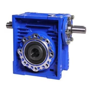
Can a Worm Gearbox be Used for High-Speed Applications?
Worm gearboxes are generally not recommended for high-speed applications due to their inherent design characteristics. Here's why:
- Efficiency: Worm gearboxes tend to have lower efficiency compared to other gearbox types, which means they can generate more heat and experience more energy loss at high speeds.
- Heat Generation: The sliding contact between the worm and worm wheel in a worm gearbox can lead to significant friction and heat generation, especially at high speeds. This heat can cause thermal expansion, affecting the gearbox's performance and longevity.
- Wear and Noise: High speeds can exacerbate wear and noise issues in worm gearboxes. Increased friction and wear can lead to faster degradation of components, resulting in reduced lifespan and increased maintenance needs.
- Backlash: Worm gearboxes may have higher backlash compared to other gearbox types, which can impact precision and accuracy in high-speed applications.
While worm gearboxes are more commonly used in applications requiring high torque and moderate speeds, they may not be the best choice for high-speed scenarios. If high-speed operation is a requirement, other gearbox types such as helical, spur, or planetary gearboxes are often better suited due to their higher efficiency, lower heat generation, and reduced wear at elevated speeds.

How to Calculate the Input and Output Speeds of a Worm Gearbox?
Calculating the input and output speeds of a worm gearbox involves understanding the gear ratio and the principles of gear reduction. Here's how you can calculate these speeds:
- Input Speed: The input speed (N1) is the speed of the driving gear, which is the worm gear in this case. It is usually provided by the manufacturer or can be measured directly.
- Output Speed: The output speed (N2) is the speed of the driven gear, which is the worm wheel. To calculate the output speed, use the formula:
N2 = N1 / (Z1 * i)
Where:
N2 = Output speed (rpm)
N1 = Input speed (rpm)
Z1 = Number of teeth on the worm gear
i = Gear ratio (ratio of the number of teeth on the worm gear to the number of threads on the worm)
It's important to note that worm gearboxes are designed for gear reduction, which means that the output speed is lower than the input speed. Additionally, the efficiency of the gearbox, friction, and other factors can affect the actual output speed. Calculating the input and output speeds is crucial for understanding the performance and capabilities of the worm gearbox in a specific application.

Lubrication Requirements for a Worm Gearbox
Lubrication is crucial for maintaining the performance and longevity of a worm gearbox. Here are the key considerations for lubricating a worm gearbox:
- Type of Lubricant: Use a high-quality, high-viscosity lubricant specifically designed for worm gearboxes. Worm gearboxes require lubricants with additives that provide proper lubrication and prevent wear.
- Lubrication Interval: Follow the manufacturer's recommendations for lubrication intervals. Regularly check the gearbox's temperature and oil condition to determine the optimal frequency of lubrication.
- Oil Level: Maintain the proper oil level to ensure effective lubrication. Too little oil can lead to insufficient lubrication, while too much oil can cause overheating and foaming.
- Lubrication Points: Identify all the lubrication points on the gearbox, including the worm and wheel gear surfaces. Apply the lubricant evenly to ensure complete coverage.
- Temperature: Consider the operating temperature of the gearbox. Some lubricants have temperature limits, and extreme temperatures can affect lubricant viscosity and performance.
- Cleanliness: Keep the gearbox and the surrounding area clean to prevent contaminants from entering the lubricant. Use proper filtration and seals to maintain a clean environment.
- Monitoring: Regularly monitor the gearbox's temperature, noise level, and vibration to detect any signs of inadequate lubrication or other issues.
Proper lubrication will reduce friction, wear, and heat generation, ensuring smooth and efficient operation of the worm gearbox. Always refer to the manufacturer's guidelines for lubrication specifications and intervals.
editor by CX 2023-09-18
China OEM Right Angle Telescope Worm Gear Speed Reducer S Saf67 Worm Gear Box Motor Reducer 90 Degree Gearbox with Great quality
Product Description
Product Parameters
Features of S series reducer
The same model can be equipped with motors of various powers. It is easy to realize the combination and connection between various models.
The transmission efficiency is high, and the single reducer efficiency is up to 96%. three
The transmission ratio is subdivided and the range is wide. The combined model can form a large transmission ratio and low output speed.
The installation forms are various, and can be installed with any foot, B5 flange or B4 flange. The foot mounting reducer has 2 machined foot mounting planes.
Helical gear and worm gear combination, compact structure, large reduction ratio.
Installation mode: foot installation, hollow shaft installation, flange installation, torque arm installation, small flange installation.
Input mode: motor direct connection, motor belt connection or input shaft, connection flange input.
Average efficiency: reduction ratio 7.5-69.39 is 77%; 70.43-288 is 62%; The S/R combination is 57%.
Detailed Photos
| Hardness: | Hardened Tooth Surface |
|---|---|
| Installation: | 90 Degree |
| Layout: | Expansion |
| Gear Shape: | Bevel Gear |
| Step: | Single-Step |
| Type: | Gear Reducer |
| Samples: |
US$ 150/Piece
1 Piece(Min.Order) | |
|---|

Is it Possible to Reverse the Direction of a Worm Gearbox?
Yes, it is possible to reverse the direction of a worm gearbox by changing the orientation of either the input or output shaft. However, reversing the direction of a worm gearbox can have some implications that need to be considered:
- Efficiency: Reversing the direction of a worm gearbox can potentially affect its efficiency. Worm gearboxes are typically more efficient in one direction of rotation due to the design of the worm and worm wheel.
- Backlash: Reversing the direction of rotation might lead to increased backlash or play in the gearbox, which can impact precision and smooth operation.
- Lubrication: Depending on the gearbox's design, reversing the direction could affect lubrication distribution and lead to uneven wear on the gear teeth.
- Load: Reversing the direction might also impact the gearbox's load-carrying capacity, especially if it's designed for predominantly one-way operation.
- Noise and Vibration: Direction reversal can sometimes result in increased noise and vibration due to changes in gear engagement and meshing behavior.
If you need to reverse the direction of a worm gearbox, it's advisable to consult the gearbox manufacturer's guidelines and recommendations. They can provide insights into whether the specific gearbox model is suitable for reversible operation and any precautions or adjustments needed to ensure proper functioning.

Worm Gearbox vs. Helical Gearbox: A Comparison
Worm gearboxes and helical gearboxes are two popular types of gear systems, each with its own set of advantages and disadvantages. Let's compare them:
| Aspect | Worm Gearbox | Helical Gearbox |
| Efficiency | Lower efficiency due to sliding friction between the worm and worm wheel. | Higher efficiency due to rolling contact between helical gear teeth. |
| Torque Transmission | Excellent torque transmission and high reduction ratios achievable in a single stage. | Good torque transmission, but may require multiple stages for high reduction ratios. |
| Noise and Vibration | Generally higher noise and vibration levels due to sliding action. | Lower noise and vibration levels due to smoother rolling contact. |
| Backlash | Higher inherent backlash due to the design. | Lower backlash due to meshing of helical teeth. |
| Efficiency at Higher Speeds | Less suitable for high-speed applications due to efficiency loss. | More suitable for high-speed applications due to higher efficiency. |
| Overload Protection | Natural self-locking feature provides some overload protection. | May not have the same level of inherent overload protection. |
| Applications | Commonly used for applications requiring high reduction ratios, such as conveyor systems and heavy-duty machinery. | Widely used in various applications including automotive transmissions, industrial machinery, and more. |
Both worm and helical gearboxes have their place in engineering, and the choice between them depends on the specific requirements of the application. Worm gearboxes are preferred for applications with high reduction ratios, while helical gearboxes are chosen for their higher efficiency and smoother operation.
Lubrication Requirements for a Worm Gearbox
Lubrication is crucial for maintaining the performance and longevity of a worm gearbox. Here are the key considerations for lubricating a worm gearbox:
- Type of Lubricant: Use a high-quality, high-viscosity lubricant specifically designed for worm gearboxes. Worm gearboxes require lubricants with additives that provide proper lubrication and prevent wear.
- Lubrication Interval: Follow the manufacturer's recommendations for lubrication intervals. Regularly check the gearbox's temperature and oil condition to determine the optimal frequency of lubrication.
- Oil Level: Maintain the proper oil level to ensure effective lubrication. Too little oil can lead to insufficient lubrication, while too much oil can cause overheating and foaming.
- Lubrication Points: Identify all the lubrication points on the gearbox, including the worm and wheel gear surfaces. Apply the lubricant evenly to ensure complete coverage.
- Temperature: Consider the operating temperature of the gearbox. Some lubricants have temperature limits, and extreme temperatures can affect lubricant viscosity and performance.
- Cleanliness: Keep the gearbox and the surrounding area clean to prevent contaminants from entering the lubricant. Use proper filtration and seals to maintain a clean environment.
- Monitoring: Regularly monitor the gearbox's temperature, noise level, and vibration to detect any signs of inadequate lubrication or other issues.
Proper lubrication will reduce friction, wear, and heat generation, ensuring smooth and efficient operation of the worm gearbox. Always refer to the manufacturer's guidelines for lubrication specifications and intervals.
editor by CX 2023-09-15