Product Description
Product Description
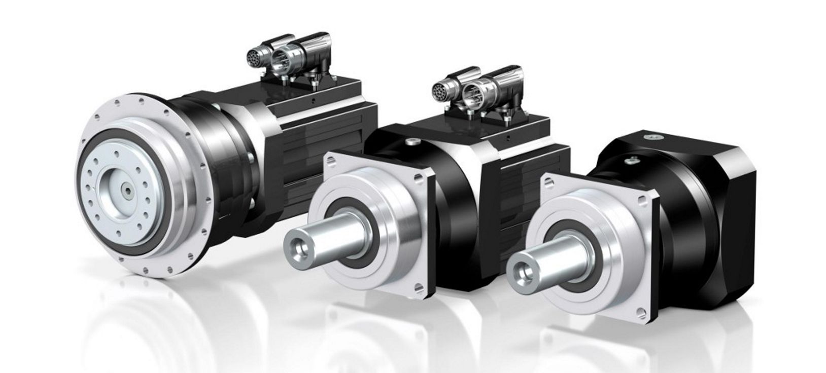
Fubao planetary reducer manufacturers, supply of 3arc/min helical gear 200mm gearbox for machine tool turret has the following advantages:
1, compact structure: the characteristics of large torque planetary reducer is to make full use of space, limited space design bearing and gear ratio, so that the product is smaller than the traditional reducer volume can save space.
2, high efficiency: the planetary gear group will be in a completely tight meshing state when running, reducing gear collision or local meshing resulting in gear damage. The completely tight meshing characteristic makes the efficiency loss of each gear transmission only 3%. This type of transmission mode can ensure that the kinetic energy input reducer to the mechanical end of the process, still can maintain high transmission efficiency, avoid the internal gear friction, sliding, mechanical loss.
3, high axial and radial load capacity: the output shaft of Fubao technology's high-torque planetary reducer adopts a large-span style, so that the bearing is configured at both ends of the output shaft. The design can effectively disperse the force acting on the output shaft and reduce the load of the bearing. In other words, the product strengthens the bearing and radial load capacity under the same size.
4, high strength: large torque planetary reducer gear group is very strong and stable, the thickness of the gear dispersed the load on the gear. The large span bearing group provides a stable structure, and the precision gear group allows the load to be distributed to each planetary gear under tight meshing to withstand the torque load.
5, high stability: precision processing to ensure that the product coaxial and concentric, coupled with bearing large span design, so that large torque planetary reducer with excellent stability.
Product Parameters
| DA series parameters | Model number | DA60 | DA090 | DA120 | DA150 |
| Rated output torque | 40~60Nm | 120~340Nm | 230~340Nm | 450~650Nm | |
| Reduction ratio | L1:3,5,7,10 L2:9,12,15,16,20,21,25,28,30,30,40,49,50,70 | ||||
| Planetary gear backlash | L1 PO≤1 P1≤3 P2≤5 L2 P0≤3 P1≤5 P2≤7 | ||||
Detailed Photos
Product Details
Other products
Company Profile
HangZhou Fubao Electromechanical Technology Co., Ltd. was established in 2008. Is a collection of scientific research, sales, service in 1 of the transmission device product supplier, committed to provide customers with good products and automation system solutions.
The compa contact-info.htmlny has a complete precision reducer design, production capacity. Set R & D, manufacturing, assembly, sales in one, in the field of gear manufacturing has more than 10 years of experience. With strong manufacturing capacity, it can steadily and continuously produce high-quality precision reducer products.
Factory Display
FAQ
Q: Speed reducer grease replacement time
A: When sealing appropriate amount of grease and running reducer, the standard replacement time is 20000 hours according to the aging condition of the grease. In addition, when the grease is stained or used in the surrounding temperature condition (above 40ºC), please check the aging and fouling of the grease, and specify the replacement time.
Q: Delivery time
A: Fubao has 2000+ production base, daily output of 1000+ units, standard models within 7 days of delivery.
Q: Reducer selection
A: Fubao provides professional product selection guidance, with higher product matching degree, higher cost performance and higher utilization rate.
Q: Application range of reducer
A: Fubao has a professional research and development team, complete category design, can match any stepping motor, servo motor, more accurate matching.
| Application: | Motor, Machinery, Agricultural Machinery |
|---|---|
| Function: | Distribution Power, Change Drive Torque, Speed Changing, Speed Reduction, Speed Increase, Lower The Speed and Increase The Torque |
| Layout: | Coaxial |
| Customization: |
Available
| Customized Request |
|---|
.shipping-cost-tm .tm-status-off{background: none;padding:0;color: #1470cc}
|
Shipping Cost:
Estimated freight per unit. |
about shipping cost and estimated delivery time. |
|---|
| Payment Method: |
|
|---|---|
|
Initial Payment Full Payment |
| Currency: | US$ |
|---|
| Return&refunds: | You can apply for a refund up to 30 days after receipt of the products. |
|---|

Handling Backlash and Ensuring Precise Positioning in Servo Gearboxes
Servo gearboxes play a critical role in minimizing backlash and ensuring precise positioning in motion control systems:
1. Reduced Backlash Gearing: Many servo gearboxes utilize reduced backlash gearing technology. This involves designing gears with tighter tolerances and improved meshing profiles, resulting in minimal play between gear teeth. This reduces or eliminates backlash, which is essential for accurate motion control.
2. Preloading: Some servo gearboxes employ preloading mechanisms to remove any gaps between gears. By applying a controlled axial load to the gears, the meshing teeth remain in constant contact, eliminating backlash and enhancing precision.
3. Stiffness and Rigidity: Servo gearboxes are designed to be stiff and rigid, which helps minimize elastic deformation under load. This stiffness prevents gear teeth from deflecting, reducing the potential for backlash and maintaining accurate positioning.
4. High Gear Meshing Quality: The manufacturing process of servo gearboxes focuses on producing high-quality gears with precise tooth profiles and minimal manufacturing variations. This ensures consistent and smooth gear meshing, minimizing the likelihood of backlash.
5. Closed-Loop Control: Combining servo gearboxes with closed-loop control systems allows for real-time feedback on position and speed. Any deviation from the desired position can be quickly corrected by adjusting the motor's output, compensating for any inherent backlash and ensuring precise positioning.
6. Advanced Gear Coatings: Some servo gearboxes incorporate advanced gear coatings or treatments that improve the meshing characteristics and reduce friction. This contributes to smoother gear engagement and minimizes backlash effects.
7. Inertia Matching: Properly matching the inertia of the load to the servo motor and gearbox combination reduces the likelihood of overshooting or oscillations during positioning. Accurate inertia matching enhances the control system's ability to maintain precise positioning.
Servo gearboxes' ability to handle backlash and ensure precise positioning is crucial for applications that require high accuracy, such as robotics, CNC machines, and automated manufacturing processes. By employing advanced design techniques and technologies, servo gearboxes contribute to achieving repeatable and accurate motion control.
Considerations for Selecting the Right Servo Gearbox for an Application
Choosing the appropriate servo gearbox for a specific application requires careful evaluation of several key factors:
1. Torque and Speed Requirements: Determine the required torque and speed characteristics of the application, ensuring that the chosen servo gearbox can provide the necessary output.
2. Gear Ratio: Calculate the ideal gear ratio based on the desired motion profile, acceleration, and deceleration requirements.
3. Mounting and Integration: Consider the available space and mechanical layout of the machinery to choose a servo gearbox with the appropriate mounting configuration.
4. Motor Compatibility: Ensure that the servo gearbox is compatible with the specific type and size of motor being used for the application.
5. Precision and Accuracy: Evaluate the level of precision required for the application's motion control. Choose a servo gearbox that can deliver the necessary accuracy and repeatability.
6. Load Distribution: Analyze how the load will be distributed among the gears to prevent excessive wear and ensure optimal performance.
7. Backlash and Compliance: Consider the application's tolerance for backlash and compliance. Choose a servo gearbox with low backlash if precise positioning is essential.
8. Environmental Conditions: Factor in the environmental conditions of the application, such as temperature, humidity, and exposure to contaminants. Choose a servo gearbox with suitable sealing and protection.
9. Lubrication: Determine the lubrication requirements of the gearbox and select a model that aligns with the application's maintenance practices.
10. Overload and Shock: Consider potential overload and shock conditions the gearbox may experience. Choose a servo gearbox that can handle sudden changes in load without compromising performance.
11. Feedback Devices: If precise motion control is required, choose a servo gearbox that is compatible with the desired feedback devices, such as encoders or resolvers.
12. Efficiency: Evaluate the efficiency of the servo gearbox to ensure that it contributes to the overall energy efficiency of the system.
13. Service and Support: Select a reputable manufacturer that offers reliable technical support, documentation, and post-purchase services.
14. Budget: Balance the performance requirements of the application with the available budget to make an informed decision.
By carefully considering these factors, engineers and designers can confidently choose the right servo gearbox that meets the specific needs of their application, optimizing performance and productivity.
Servo Gearboxes vs. Standard Gearboxes in Industrial Applications
Servo gearboxes and standard gearboxes serve distinct roles in industrial applications. Here's how they differ:
Precision Control: Servo gearboxes are specifically designed for precise motion control in applications that require accurate speed and position control. Standard gearboxes, while also providing speed reduction or torque multiplication, may not offer the same level of precision.
Backlash: Servo gearboxes are designed to minimize backlash, which is crucial for applications where even slight lost motion is unacceptable. Standard gearboxes may have higher levels of backlash due to their broader design scope.
Dynamic Response: Servo gearboxes excel in dynamic response, enabling quick changes in speed and direction with minimal overshoot. Standard gearboxes may not offer the same level of responsiveness.
High Efficiency: Servo gearboxes are optimized for efficiency to ensure precise power transmission. Standard gearboxes may prioritize other factors like cost or load capacity.
Positioning Accuracy: Servo gearboxes are essential for achieving high positioning accuracy in applications such as robotics and CNC machines. Standard gearboxes might not meet the same accuracy requirements.
Load Distribution: Servo gearboxes distribute loads evenly across gear teeth to enhance durability and minimize wear. Standard gearboxes might not have the same load distribution capabilities.
Compact Design: Servo gearboxes are often designed with a compact form factor to fit within tight spaces. Standard gearboxes might be larger and less optimized for space constraints.
Customization: Servo gearboxes can be highly customizable in terms of size, reduction ratio, and mounting options. Standard gearboxes may offer fewer customization choices.
Application Focus: Servo gearboxes are intended for applications that demand precision and responsiveness, such as robotics, automation, and CNC machining. Standard gearboxes are used in a broader range of applications where precision might not be as critical.
In summary, servo gearboxes are specialized components tailored for high-precision motion control applications, while standard gearboxes serve a wider variety of industrial needs with a focus on durability, load handling, and basic speed reduction.


editor by CX 2023-11-16
China Standard Customize Planetary Gear Box Transmission for Servo Motor Injection Molding Take-out Robot CNC Machine Atuomatic Tools Change with Best Sales
Product Description
Note:
The specifications can be designed according to the customer's requirements!
Application:
Food Beverage, Printing, Agriculture, CNC Machine, CNC Atuomatic Tools Change
Parameter:
Gearbox Electrical Specifications
| Reducer Series | 1 |
| Transmission efficiency | >=90% |
| Max radial load | ≤200N |
| Max axial load | ≤100N |
| Transmission torque | 15N.m |
| Reduction Ratio | 10/1 |
| Length(mm) | 95 |
| Note: We can manufacture products according to customer's requirements. | |
About Us:
We specialized in researching, developing, and servicing electric motors, gearbox, and high precision gears with the small module. After years of development, we have an independent product design and R&D team, service team, and a professional quality control team. To realize our service concept better, provide high-quality products and excellent service, we have been committed to the core ability and training. We have a holding factory in HangZhou, which produces high precision small mold gears, gear shaft, gearbox, and planetary gearbox assembling.
Work-flow:
Certificate:
RoHS, CE, and more...
Service:
ODM & OEM
Gearbox design and development
Package&Ship:
Carton, pallet, or what you want
The delivery time is about 30-45 days.
Customer's Visiting:
FAQ:
1. Can you custom gearbox?
YES.
2. DO you provide the sample?
YES.
3. Do you provide technical support?
YES
4. Do you have a factory?
Yes, we are a professional manufacturer.
5. Can I come to your company to visit?
YES
| Transmission Torque: | 15n.M |
|---|---|
| Length(mm): | 95 |
| Ratio: | 10/1 |
| Max Radial Load: | 200n |
| Transmission Efficiency: | >=90% |
| Transport Package: | Carton or Pallet |
| Samples: |
US$ 200/Piece
1 Piece(Min.Order) | |
|---|
| Customization: |
Available
| Customized Request |
|---|

The Role of Harmonic Drive Servo Gearboxes in Advanced Motion Control Systems
Harmonic Drive servo gearboxes play a crucial role in advanced motion control systems by offering several unique features:
1. High Precision: Harmonic Drive gearboxes are known for their exceptional precision due to the unique gear mechanism they employ. This precision is essential for achieving accurate and repeatable motion control.
2. Zero Backlash: Harmonic Drive gearboxes are designed with zero backlash, which means there is no lost motion between input and output. This feature ensures that the commanded motion is precisely transferred without any delays or inaccuracies.
3. Compact Design: Harmonic Drive gearboxes have a compact structure, making them suitable for applications with limited space. The compact design allows for easy integration into various systems.
4. High Torque Transmission: Despite their compact size, harmonic drive gearboxes can transmit high torque efficiently. This feature is essential for applications that require both high precision and high torque.
5. Smooth Motion: The unique wave generator mechanism in harmonic drive gearboxes contributes to smooth and continuous motion, which is particularly beneficial in applications involving robotic arms, satellite positioning, and more.
6. Reduction Ratios: Harmonic Drive gearboxes offer high reduction ratios in a single-stage, allowing for precise control of output motion even when input motion is at high speeds.
7. Low Maintenance: The absence of backlash and the use of high-quality materials result in reduced wear and maintenance requirements, enhancing the longevity of the gearbox.
8. Advanced Applications: Harmonic Drive gearboxes are commonly used in robotics, aerospace, medical equipment, automation, and other industries where precision and reliability are paramount.
Overall, harmonic drive servo gearboxes are a critical component in achieving advanced motion control, enabling engineers to design and operate complex systems with unparalleled precision and accuracy.
Customization of Servo Gearboxes for Specific Industrial Needs
Servo gearboxes can indeed be customized to meet specific industrial requirements. Manufacturers offer customization options to ensure that the servo gearboxes are optimized for the intended applications:
1. Gear Ratio Selection: Depending on the desired speed and torque output, manufacturers can provide various gear ratios to achieve the required motion characteristics.
2. Torque and Speed Ratings: Servo gearboxes can be tailored to handle different torque and speed demands, ensuring that they can efficiently operate within the specified parameters of the application.
3. Mounting Configurations: Manufacturers offer various mounting options, such as flange mounts or shaft mounts, to suit the mechanical layout of the machinery.
4. Output Shaft Configuration: Custom output shaft configurations, such as different diameters or keyway options, can be provided based on the integration requirements.
5. Environmental Considerations: For applications with specific environmental conditions, such as high humidity or extreme temperatures, servo gearboxes can be designed with protective features or special coatings.
6. Lubrication and Sealing: Custom lubrication options and sealing mechanisms can be incorporated to ensure optimal performance and longevity in the given environment.
7. Feedback Devices: Some applications may require specific feedback devices, such as encoders or resolvers, for precise motion control. Manufacturers can integrate these devices into the gearbox design.
8. Noise Reduction: Customized designs can include features that reduce noise and vibration, which is crucial in noise-sensitive applications.
9. Compact Designs: Manufacturers can work on compact designs to accommodate space constraints in the machinery.
10. Integration with Motors: Customized servo gearboxes can be designed to seamlessly integrate with specific types of motors, ensuring efficient power transmission.
By offering customization options, manufacturers enable industries to obtain servo gearboxes that perfectly align with their unique industrial needs, ultimately enhancing performance, precision, and overall system efficiency.

Benefits of Using a Servo Gearbox for Precise Motion Control
Servo gearboxes offer several advantages when it comes to achieving precise motion control in various applications:
1. Accuracy: Servo gearboxes provide exceptional accuracy in speed and position control, making them suitable for applications that require tight tolerances and precise movements.
2. Low Backlash: These gearboxes are designed to minimize backlash, which is essential for eliminating lost motion and ensuring accurate positioning.
3. High Torque Density: Servo gearboxes offer a high torque-to-size ratio, allowing them to handle significant loads while maintaining a compact footprint.
4. Dynamic Performance: They excel in dynamic performance, enabling rapid changes in speed and direction with minimal overshoot or settling time.
5. Responsiveness: Servo gearboxes respond quickly to control signals, making them ideal for applications that require rapid adjustments and changes in direction.
6. Smooth Operation: These gearboxes provide smooth and precise movement, critical for applications like robotics, where jerky or uneven motion can lead to inaccuracies or damage.
7. Reduces Maintenance: The accuracy and durability of servo gearboxes can reduce wear and tear on other components, leading to lower maintenance requirements.
8. Improved Efficiency: Servo gearboxes offer high efficiency in power transmission, contributing to energy savings and minimizing heat generation.
9. Customization: They can be tailored to specific application needs, including factors like reduction ratios, mounting options, and feedback compatibility.
10. Versatility: Servo gearboxes find application in various industries, including robotics, CNC machining, medical equipment, and automation.
Overall, the benefits of using a servo gearbox for precise motion control make them an essential component in applications that demand accuracy, responsiveness, and reliable performance.
editor by CX 2023-10-07
China factory Low Noise Big Torque Worm Gear Box with Electric Motor gearbox adjustment
Product Description
| Product Description |
Our Gearbox has many items for your choosing and we can produce as per your drawing or sample to meet your special request
1. Large output torque
2. Safe, reliable, economical and durable
3. Stable transmission, quiet operation
4. High carrying ability
5. High modularization design, may equip with various outer power input conveniently. Same machine type may equip with various power motor. It is easy to realize the combination and junction between every machine type
6. Transmission ratio: Fine division, wide scope. The combined machine type may form very large transmission ratio, i. E. Output very low rotary speed.
7. Form of installation: The position to be installed is not limited.
8. High strength, compact the box body of high strength cast iron, gear and gear shaft adapts the gas carbonization, quenching and fine grinding process, therefore the bearing capacity of unit volume is high.
9. Long life: Under the condition of correct type chosen(including choosing suitable operation parament ) normal operation and maintenance, the life if main parts speed reducer(except wearing parts)should not be less than 20000 hours. The wearing parts include lubricating oil, oil seal and bearing.
10. Low noise: Because main parts of speed reducer are processed, and tested critically, therefore the noise of speed reducer is low.
11.Our gear box have reached the advance international level, can replace the same kind of products imported.
|
Size |
Ratio |
A |
B |
E |
F |
H |
M |
N |
|
40 |
1/5 1/10 1/15 1/20 1/25 1/30 1/40 1/50 1/60 |
142 |
112 |
70 |
80 |
135 |
90 |
100 |
|
50 |
175 |
145 |
95 |
110 |
180 |
120 |
140 |
|
|
60 |
195 |
165 |
105 |
120 |
210 |
130 |
150 |
|
|
70 |
234 |
195 |
115 |
150 |
243 |
150 |
190 |
|
|
80 |
264 |
210 |
135 |
180 |
273 |
170 |
220 |
|
|
100 |
300 |
245 |
155 |
220 |
340 |
190 |
260 |
|
|
120 |
385 |
285 |
180 |
260 |
405 |
230 |
320 |
|
|
135 |
435 |
320 |
200 |
290 |
455 |
250 |
350 |
|
|
155 |
507 |
387 |
220 |
320 |
490 |
280 |
390 |
|
|
175 |
550 |
407 |
250 |
350 |
565 |
310 |
430 |
|
|
200 |
594 |
480 |
290 |
390 |
625 |
360 |
480 |
|
|
250 |
710 |
560 |
380 |
480 |
730 |
460 |
560 |
|
Size |
G |
Z |
Input Shaft |
Output Shaft |
Weight Kg |
Oil Weight L |
||
|
HS |
U |
LS |
S |
|||||
|
40 |
12 |
10 |
25 |
12 |
28 |
14 |
3.8 |
0.14 |
|
50 |
15 |
11 |
30 |
12 |
40 |
17 |
7 |
0.17 |
|
60 |
20 |
11 |
40 |
15 |
50 |
22 |
10.5 |
0.23 |
|
70 |
20 |
15 |
40 |
18 |
60 |
28 |
14.5 |
0.5 |
|
80 |
20 |
15 |
50 |
22 |
65 |
32 |
22 |
0.7 |
|
100 |
25 |
15 |
50 |
25 |
75 |
38 |
36 |
1.6 |
|
120 |
30 |
18 |
65 |
30 |
85 |
45 |
63 |
3.0 |
|
135 |
30 |
18 |
75 |
35 |
95 |
55 |
80 |
3.5 |
|
155 |
38 |
20 |
85 |
40 |
110 |
60 |
114 |
3.6 |
|
175 |
40 |
20 |
85 |
45 |
110 |
65 |
150 |
4.5 |
|
200 |
42 |
22 |
95 |
50 |
125 |
70 |
218 |
6.4 |
|
250 |
42 |
27 |
110 |
60 |
155 |
90 |
363 |
8.5 |
|
Size |
Ratio |
A |
B |
E |
F |
H |
M |
N |
|
40 |
1/5 1/10 1/15 1/20 1/25 1/30 1/40 1/50 1/60 |
142 |
85 |
70 |
80 |
135 |
90 |
100 |
|
50 |
175 |
105 |
95 |
110 |
180 |
120 |
140 |
|
|
60 |
195 |
120 |
105 |
120 |
205 |
130 |
150 |
|
|
70 |
234 |
140 |
115 |
150 |
235 |
150 |
190 |
|
|
80 |
264 |
160 |
135 |
180 |
265 |
170 |
220 |
|
|
100 |
300 |
178 |
155 |
220 |
327 |
190 |
260 |
|
|
120 |
385 |
230 |
180 |
260 |
388 |
230 |
320 |
|
|
135 |
435 |
260 |
200 |
290 |
445 |
250 |
350 |
|
|
155 |
507 |
300 |
220 |
320 |
483 |
280 |
390 |
|
|
175 |
550 |
325 |
250 |
350 |
550 |
310 |
430 |
|
|
200 |
594 |
350 |
290 |
390 |
610 |
360 |
480 |
|
|
250 |
710 |
420 |
380 |
480 |
755 |
460 |
560 |
|
Size |
G |
Z |
Input Shaft |
Output Shaft |
Weight Kg |
Oil Weight |
||
|
HS |
U |
LS |
S |
|||||
|
40 |
12 |
10 |
25 |
12 |
28 |
14 |
3.8 |
|
|
50 |
15 |
11 |
30 |
12 |
40 |
17 |
7 |
0.4 |
|
60 |
20 |
11 |
40 |
15 |
50 |
22 |
10.5 |
0.5 |
|
70 |
25 |
15 |
40 |
18 |
60 |
28 |
14.5 |
0.7 |
|
80 |
25 |
15 |
50 |
22 |
65 |
32 |
22 |
1.1 |
|
100 |
25 |
15 |
50 |
25 |
75 |
38 |
36 |
2.3 |
|
120 |
30 |
18 |
65 |
30 |
85 |
45 |
63 |
4.5 |
|
135 |
30 |
18 |
75 |
35 |
95 |
55 |
80 |
6.0 |
|
155 |
38 |
20 |
85 |
40 |
110 |
60 |
114 |
6.2 |
|
175 |
40 |
20 |
85 |
45 |
110 |
65 |
150 |
8.0 |
|
200 |
42 |
22 |
95 |
50 |
125 |
70 |
218 |
9.0 |
|
250 |
48 |
27 |
110 |
60 |
155 |
90 |
363 |
17.0 |
|
Size |
Ratio |
A |
B |
E1 |
E2 |
F |
G |
M |
N |
|
40 |
1/5 1/10 1/15 1/20 1/25 1/30 1/40 1/50 1/60 |
142 |
85 |
72 |
85 |
75 |
12 |
179 |
97 |
|
50 |
175 |
105 |
93 |
102 |
90 |
14 |
220 |
116 |
|
|
60 |
195 |
120 |
105 |
120 |
100 |
15 |
260 |
126 |
|
|
70 |
234 |
140 |
120 |
135 |
120 |
20 |
295 |
156 |
|
|
80 |
264 |
160 |
130 |
150 |
140 |
20 |
320 |
176 |
|
|
100 |
300 |
178 |
155 |
180 |
190 |
30 |
375 |
226 |
|
|
120 |
385 |
230 |
185 |
215 |
220 |
30 |
450 |
266 |
|
|
135 |
435 |
260 |
210 |
235 |
260 |
35 |
495 |
306 |
|
|
155 |
507 |
300 |
245 |
295 |
290 |
45 |
590 |
350 |
|
|
175 |
550 |
325 |
267 |
323 |
320 |
45 |
640 |
394 |
|
|
200 |
594 |
350 |
290 |
360 |
370 |
42 |
710 |
440 |
|
|
250 |
710 |
420 |
350 |
440 |
440 |
46 |
860 |
510 |
HangZhou CHINAMFG Industry Co., Ltd. is a specialized supplier of a full range of chains, sprockets, gears, gear racks, v belt pulley, timing pulley, V-belts, couplings, machined parts and so on.
Due to our CHINAMFG in offering best service to our clients, understanding of your needs and overriding sense of responsibility toward filling ordering requirements, we have obtained the trust of buyers worldwide. Having accumulated precious experience in cooperating with foreign customers, our products are selling well in the American, European, South American and Asian markets. Our products are manufactured by modern computerized machinery and equipment. Meanwhile, our products are manufactured according to high quality standards, and complying with the international advanced standard criteria.
With many years' experience in this line, we will be trusted by our advantages in competitive price, one-time delivery, prompt response, on-hand engineering support and good after-sales services.
Additionally, all our production procedures are in compliance with ISO9001 standards. We also can design and make non-standard products to meet customers' special requirements. Quality and credit are the bases that make a corporation alive. We will provide best services and high quality products with all sincerity. If you need any information or samples, please contact us and you will have our soon reply.
FAQ:
Q1: Are you trading company or manufacturer ?
A: We are factory.
Q2: How long is your delivery time and shipment?
1.Sample Lead-times: generally 10 workdays.
2.Production Lead-times: 20-40 workdays after getting your deposit.
Q3. What is your terms of payment?
A: T/T 30% as deposit, and 70% before delivery.
Q4: What is your advantages?
1. Manufacturer,the most competitive price and good quality.
2. Perfect technical engineers give you the best support.
3. OEM is available.
4. Rich stock and quick delivery.
Q5. If you can't find the product on our website,what do you next?
Please send us inquiry with product pictures and drawings by email or other ways and we'll check.
|
Shipping Cost:
Estimated freight per unit. |
To be negotiated |
|---|
| Application: | Machinery, Marine, Agricultural Machinery |
|---|---|
| Function: | Speed Changing |
| Layout: | Cycloidal |
| Samples: |
US$ 120/Piece
1 Piece(Min.Order) | Order Sample |
|---|
| Customization: |
Available
| Customized Request |
|---|

Calculating Gear Ratio in a Worm Reducer
The gear ratio in a worm reducer is determined by the number of teeth on the worm wheel (also known as the worm gear) and the number of threads on the worm shaft. The gear ratio formula for a worm reducer is:
Gear Ratio = Number of Teeth on Worm Wheel / Number of Threads on Worm Shaft
For example, if the worm wheel has 60 teeth and the worm shaft has a single thread, the gear ratio would be 60:1.
It's important to note that worm reducers have an inherent self-locking property due to the angle of the worm threads. As a result, the gear ratio also affects the mechanical advantage and the system's ability to resist backdriving.
When calculating the gear ratio, ensure that the worm reducer is properly designed and that the gear ratio aligns with the desired mechanical characteristics for your application. Additionally, consider factors such as efficiency, load capacity, and speed limitations when selecting a gear ratio for a worm reducer.

How to Calculate the Input and Output Speeds of a Worm Gearbox?
Calculating the input and output speeds of a worm gearbox involves understanding the gear ratio and the principles of gear reduction. Here's how you can calculate these speeds:
- Input Speed: The input speed (N1) is the speed of the driving gear, which is the worm gear in this case. It is usually provided by the manufacturer or can be measured directly.
- Output Speed: The output speed (N2) is the speed of the driven gear, which is the worm wheel. To calculate the output speed, use the formula:
N2 = N1 / (Z1 * i)
Where:
N2 = Output speed (rpm)
N1 = Input speed (rpm)
Z1 = Number of teeth on the worm gear
i = Gear ratio (ratio of the number of teeth on the worm gear to the number of threads on the worm)
It's important to note that worm gearboxes are designed for gear reduction, which means that the output speed is lower than the input speed. Additionally, the efficiency of the gearbox, friction, and other factors can affect the actual output speed. Calculating the input and output speeds is crucial for understanding the performance and capabilities of the worm gearbox in a specific application.

How Does a Worm Gearbox Compare to Other Types of Gearboxes?
Worm gearboxes offer unique advantages and characteristics that set them apart from other types of gearboxes. Here's a comparison between worm gearboxes and some other common types:
- Helical Gearbox: Worm gearboxes have higher torque multiplication, making them suitable for heavy-load applications, while helical gearboxes are more efficient and offer smoother operation.
- Bevel Gearbox: Worm gearboxes are compact and can transmit motion at right angles, similar to bevel gearboxes, but worm gearboxes have self-locking capabilities.
- Planetary Gearbox: Worm gearboxes provide high torque output and are cost-effective for applications with high reduction ratios, whereas planetary gearboxes offer higher efficiency and can handle higher input speeds.
- Spur Gearbox: Worm gearboxes have better shock load resistance due to their sliding motion, while spur gearboxes are more efficient and suitable for lower torque applications.
- Cycloidal Gearbox: Cycloidal gearboxes have high shock load capacity and compact design, but worm gearboxes are more cost-effective and can handle higher reduction ratios.
While worm gearboxes have advantages such as high torque output, compact design, and self-locking capability, the choice between gearbox types depends on the specific requirements of the application, including torque, efficiency, speed, and space limitations.
editor by CX 2023-09-18
China supplier Nmrv Right Angle 90 Degree Transmission Worm Drive Gear Box Gearbox with Motor with high quality
Product Description
NMRV right angle 90 degree transmission worm drive gear box gearbox with motor
Features:
1. Light in weight and non-rusting
2. Smooth in running, can work long time in dreadful conditions
3. High efficiency, low noise
4. Good-looking in appearance, durable in service life and small in volume
Product photo:
Specification for worm reducer:
| Model | 571 ~ 150 |
| Power | 0.06kw ~ 15kw |
| Input speed | 750rpm ~ 2000rpm |
| Reduction ratio | 1/5 ~ 1/100 |
| Input motor | AC (1 phase or 3 phase) / DC / BLDC / Stepper / Servo |
| Output shaft | Solid shaft / Hollow shaft / Output flange… |
| Dimension standard | Metric size / Inch size |
| Material of housing | die-cast aluminum / Cast iron / Stainless steel |
| Accessories | Flange / CHINAMFG shaft / Torque arm / Cover … |
FAQ
Q: Can you make the reducer with customization?
A: Yes, we can customize per your request, like flange, shaft, configuration, material, etc.
Q: Do you provide samples?
A: Yes. Sample is available for testing.
Q: What is your MOQ?
A: It is 10pcs for the beginning of our business.
Q: What's your lead time?
A: Standard product need 5-30days, a bit longer for customized products.
Q: Do you provide technology support?
A: Yes. Our company have design and development team, we can provide technology support if you
need.
Q: How to ship to us?
A: It is available by air, or by sea, or by train.
Q: How to pay the money?
A: T/T and L/C is preferred, with different currency, including USD, EUR, RMB, etc.
Q: How can I know the product is suitable for me?
A: >1ST confirm drawing and specification >2nd test sample >3rd start mass production.
Q: Can I come to your company to visit?
A: Yes, you are welcome to visit us at any time.
Q: How shall we contact you?
A: You can send inquiry directly, and we will respond within 24 hours.
| Application: | Machinery |
|---|---|
| Function: | Change Drive Torque, Speed Changing, Speed Reduction |
| Layout: | Right Angle |
| Hardness: | Hardened Tooth Surface |
| Installation: | Horizontal Type |
| Step: | Single-Step |
| Samples: |
US$ 50/Piece
1 Piece(Min.Order) | |
|---|
| Customization: |
Available
| Customized Request |
|---|

How to Install and Align a Worm Reducer Properly
Proper installation and alignment of a worm reducer are crucial for ensuring optimal performance and longevity. Follow these steps to install and align a worm reducer:
- Preparation: Gather all the necessary tools, equipment, and safety gear before starting the installation process.
- Positioning: Place the worm reducer in the desired location, ensuring that it is securely mounted to a stable surface. Use appropriate fasteners and mounting brackets as needed.
- Shaft Alignment: Check the alignment of the input and output shafts. Use precision measurement tools to ensure that the shafts are parallel and in line with each other.
- Base Plate Alignment: Align the base plate of the reducer with the foundation or mounting surface. Ensure that the base plate is level and properly aligned before securing it in place.
- Bolt Tightening: Gradually and evenly tighten the mounting bolts to the manufacturer's specifications. This helps ensure proper contact between the reducer and the mounting surface.
- Check for Clearance: Verify that there is enough clearance for any rotating components or parts that may move during operation. Avoid any interference that could cause damage or performance issues.
- Lubrication: Apply the recommended lubricant to the worm reducer according to the manufacturer's guidelines. Proper lubrication is essential for smooth operation and reducing friction.
- Alignment Testing: After installation, run the worm reducer briefly without a load to check for any unusual noises, vibrations, or misalignment issues.
- Load Testing: Gradually introduce the intended load to the worm reducer and monitor its performance. Ensure that the reducer operates smoothly and efficiently under the load conditions.
It's important to refer to the manufacturer's installation guidelines and specifications for your specific worm reducer model. Proper installation and alignment will contribute to the gearbox's reliability, efficiency, and overall functionality.

How to Calculate the Efficiency of a Worm Gearbox
Calculating the efficiency of a worm gearbox involves determining the ratio of output power to input power. Efficiency is a measure of how well the gearbox converts input power into useful output power without losses. Here's how to calculate it:
- Step 1: Measure Input Power: Measure the input power (Pin) using a power meter or other suitable measuring equipment.
- Step 2: Measure Output Power: Measure the output power (Pout) that the gearbox is delivering to the load.
- Step 3: Calculate Efficiency: Calculate the efficiency (η) using the formula: Efficiency (η) = (Output Power / Input Power) * 100%
For example, if the input power is 1000 watts and the output power is 850 watts, the efficiency would be (850 / 1000) * 100% = 85%.
It's important to note that efficiencies can vary based on factors such as gear design, lubrication, wear, and load conditions. The calculated efficiency provides insight into how effectively the gearbox is converting power, but it's always a good practice to refer to manufacturer specifications for gearbox efficiency ratings.
How Does a Worm Gearbox Compare to Other Types of Gearboxes?
Worm gearboxes offer unique advantages and characteristics that set them apart from other types of gearboxes. Here's a comparison between worm gearboxes and some other common types:
- Helical Gearbox: Worm gearboxes have higher torque multiplication, making them suitable for heavy-load applications, while helical gearboxes are more efficient and offer smoother operation.
- Bevel Gearbox: Worm gearboxes are compact and can transmit motion at right angles, similar to bevel gearboxes, but worm gearboxes have self-locking capabilities.
- Planetary Gearbox: Worm gearboxes provide high torque output and are cost-effective for applications with high reduction ratios, whereas planetary gearboxes offer higher efficiency and can handle higher input speeds.
- Spur Gearbox: Worm gearboxes have better shock load resistance due to their sliding motion, while spur gearboxes are more efficient and suitable for lower torque applications.
- Cycloidal Gearbox: Cycloidal gearboxes have high shock load capacity and compact design, but worm gearboxes are more cost-effective and can handle higher reduction ratios.
While worm gearboxes have advantages such as high torque output, compact design, and self-locking capability, the choice between gearbox types depends on the specific requirements of the application, including torque, efficiency, speed, and space limitations.
editor by CX 2023-09-18
China OEM Right Angle Telescope Worm Gear Speed Reducer S Saf67 Worm Gear Box Motor Reducer 90 Degree Gearbox with Great quality
Product Description
Product Parameters
Features of S series reducer
The same model can be equipped with motors of various powers. It is easy to realize the combination and connection between various models.
The transmission efficiency is high, and the single reducer efficiency is up to 96%. three
The transmission ratio is subdivided and the range is wide. The combined model can form a large transmission ratio and low output speed.
The installation forms are various, and can be installed with any foot, B5 flange or B4 flange. The foot mounting reducer has 2 machined foot mounting planes.
Helical gear and worm gear combination, compact structure, large reduction ratio.
Installation mode: foot installation, hollow shaft installation, flange installation, torque arm installation, small flange installation.
Input mode: motor direct connection, motor belt connection or input shaft, connection flange input.
Average efficiency: reduction ratio 7.5-69.39 is 77%; 70.43-288 is 62%; The S/R combination is 57%.
Detailed Photos
| Hardness: | Hardened Tooth Surface |
|---|---|
| Installation: | 90 Degree |
| Layout: | Expansion |
| Gear Shape: | Bevel Gear |
| Step: | Single-Step |
| Type: | Gear Reducer |
| Samples: |
US$ 150/Piece
1 Piece(Min.Order) | |
|---|

Is it Possible to Reverse the Direction of a Worm Gearbox?
Yes, it is possible to reverse the direction of a worm gearbox by changing the orientation of either the input or output shaft. However, reversing the direction of a worm gearbox can have some implications that need to be considered:
- Efficiency: Reversing the direction of a worm gearbox can potentially affect its efficiency. Worm gearboxes are typically more efficient in one direction of rotation due to the design of the worm and worm wheel.
- Backlash: Reversing the direction of rotation might lead to increased backlash or play in the gearbox, which can impact precision and smooth operation.
- Lubrication: Depending on the gearbox's design, reversing the direction could affect lubrication distribution and lead to uneven wear on the gear teeth.
- Load: Reversing the direction might also impact the gearbox's load-carrying capacity, especially if it's designed for predominantly one-way operation.
- Noise and Vibration: Direction reversal can sometimes result in increased noise and vibration due to changes in gear engagement and meshing behavior.
If you need to reverse the direction of a worm gearbox, it's advisable to consult the gearbox manufacturer's guidelines and recommendations. They can provide insights into whether the specific gearbox model is suitable for reversible operation and any precautions or adjustments needed to ensure proper functioning.

Worm Gearbox vs. Helical Gearbox: A Comparison
Worm gearboxes and helical gearboxes are two popular types of gear systems, each with its own set of advantages and disadvantages. Let's compare them:
| Aspect | Worm Gearbox | Helical Gearbox |
| Efficiency | Lower efficiency due to sliding friction between the worm and worm wheel. | Higher efficiency due to rolling contact between helical gear teeth. |
| Torque Transmission | Excellent torque transmission and high reduction ratios achievable in a single stage. | Good torque transmission, but may require multiple stages for high reduction ratios. |
| Noise and Vibration | Generally higher noise and vibration levels due to sliding action. | Lower noise and vibration levels due to smoother rolling contact. |
| Backlash | Higher inherent backlash due to the design. | Lower backlash due to meshing of helical teeth. |
| Efficiency at Higher Speeds | Less suitable for high-speed applications due to efficiency loss. | More suitable for high-speed applications due to higher efficiency. |
| Overload Protection | Natural self-locking feature provides some overload protection. | May not have the same level of inherent overload protection. |
| Applications | Commonly used for applications requiring high reduction ratios, such as conveyor systems and heavy-duty machinery. | Widely used in various applications including automotive transmissions, industrial machinery, and more. |
Both worm and helical gearboxes have their place in engineering, and the choice between them depends on the specific requirements of the application. Worm gearboxes are preferred for applications with high reduction ratios, while helical gearboxes are chosen for their higher efficiency and smoother operation.

Lubrication Requirements for a Worm Gearbox
Lubrication is crucial for maintaining the performance and longevity of a worm gearbox. Here are the key considerations for lubricating a worm gearbox:
- Type of Lubricant: Use a high-quality, high-viscosity lubricant specifically designed for worm gearboxes. Worm gearboxes require lubricants with additives that provide proper lubrication and prevent wear.
- Lubrication Interval: Follow the manufacturer's recommendations for lubrication intervals. Regularly check the gearbox's temperature and oil condition to determine the optimal frequency of lubrication.
- Oil Level: Maintain the proper oil level to ensure effective lubrication. Too little oil can lead to insufficient lubrication, while too much oil can cause overheating and foaming.
- Lubrication Points: Identify all the lubrication points on the gearbox, including the worm and wheel gear surfaces. Apply the lubricant evenly to ensure complete coverage.
- Temperature: Consider the operating temperature of the gearbox. Some lubricants have temperature limits, and extreme temperatures can affect lubricant viscosity and performance.
- Cleanliness: Keep the gearbox and the surrounding area clean to prevent contaminants from entering the lubricant. Use proper filtration and seals to maintain a clean environment.
- Monitoring: Regularly monitor the gearbox's temperature, noise level, and vibration to detect any signs of inadequate lubrication or other issues.
Proper lubrication will reduce friction, wear, and heat generation, ensuring smooth and efficient operation of the worm gearbox. Always refer to the manufacturer's guidelines for lubrication specifications and intervals.
editor by CX 2023-09-15
China Best Sales S Series Helical Worm Variable Speed Gear Box with Motor cycloidal gearbox
Product Description
S Series Helical Worm Variable Speed Gear Box with Motor
1. Product Characteristics
S series helical worm gearbox adopts the helical worm gears to make its structure more reasonable. S series not only has higher transmission efficency and loading capability than those single-stage worm wheel transmission, but also smaller volume and appearance. Moreover, S series worm gearbox has higher transmission ratio, and can be combined with various gearboxes and speed variators to meet the different requirements.
2. Technical Data
| Rated Power | 0.18~22KW |
| Output Speed | 0.16~147r/min |
| Output Torque | 90~4000N.m |
| Mounted Form | Foot-mounted, flange mounted, shaft-mounted, torque arm mounted |
| Housing | Aluminum and Casting Iron |
3. Structure
S series gearbox are available in the following designs:
(1) SY Foot mounted helical worm gearbox with CHINAMFG shaft
(2) SAY Helical worm gearbox with hollow shaft
(3) SAZY Small flange mounted helical worm gearbox with hollow shaft
(4) SA (S,SF,SAF,SAZ)Y Assemble users' motor or special motor, flange is required
(5) SFY Flange mounted helical worm gearbox with CHINAMFG shaft
(6) SAFY Flange mounted helical worm gearbox with hollow shaft
(7) SATY Torque arm mounted helical worm gearbox with hollow shaft
(8) S (SF,SA,SAF,SAZ) S Shaft input helical worm gearbox
(9) SA (S,SF,SAF,SAZ)RY Combined helical worm gearbox
(10) SA (S,SF,SAF,SAZ)SR Shaft input combined helical worm gearbox
4. Detailed parameters
| Size | 38 | 48 | 58 | 68 | 78 | 88 | 98 |
| Structure | S SA SF SAF SAT SAZ | ||||||
| Input Power(KW) | 0.18-0.75 | 0.18-1.5 | 0.18-3 | 0.25-5.5 | 0.55-7.5 | 0.75-15 | 1.5-22 |
| Ratio | 10.27-152 | 11.46-244.74 | 10.78-196.21 | 11.55-227.20 | 9.96-241.09 | 11.83-222 | 12.75-230.48 |
| Maximum torque(N.m) | 90 | 170 | 295 | 520 | 1270 | 2280 | 4000 |
5.Product Pictures:
6.Our company :
AOKMAN was founded in 1982, which has more than 36 years in R & D and manufacturing of gearboxes, gears, shaft, motor and spare parts.
We can offer the proper solution for uncountable applications. Our products are widely used in the ranges of metallurgical, steel, mining, pulp and paper, sugar and alcohol market and various other types of machines with a strong presence in the international market.
AOKMAN has become a reliable supplier, able to supply high quality gearboxes.With 36 years experience, we assure you the utmost reliability and security for both product and services.
7.Customer visiting:
8.Our Services:
| Pre-sale services | 1. Select equipment model. |
| 2.Design and manufacture products according to clients' special requirement. | |
| 3.Train technical personal for clients | |
| Services during selling | 1.Pre-check and accept products ahead of delivery. |
| 2. Help clients to draft solving plans. | |
| After-sale services | 1.Assist clients to prepare for the first construction scheme. |
| 2. Train the first-line operators. | |
| 3.Take initiative to eliminate the trouble rapidly. | |
| 4. Provide technical exchanging. |
9.FAQ:
1.Q:What kinds of gearbox can you produce for us?
A:Main products of our company: UDL series speed variator,RV series worm gear reducer, ATA series shaft mounted gearbox, X,B series gear reducer,
P series planetary gearbox and R, S, K, and F series helical-tooth reducer, more
than 1 hundred models and thousands of specifications
2.Q:Can you make as per custom drawing?
A: Yes, we offer customized service for customers.
3.Q:What is your terms of payment ?
A: 30% Advance payment by T/T after signing the contract.70% before delivery
4.Q:What is your MOQ?
A: 1 Set
If you have any demand for our products please feel free to contact me.
| Application: | Machinery, Reducer |
|---|---|
| Function: | Change Drive Torque, Speed Changing, Speed Reduction |
| Layout: | Right Angle |
| Hardness: | Hardened |
| Type: | Worm and Wormwheel |
| Material: | Cast Iron |
| Customization: |
Available
| Customized Request |
|---|
How to Install and Align a Worm Reducer Properly
Proper installation and alignment of a worm reducer are crucial for ensuring optimal performance and longevity. Follow these steps to install and align a worm reducer:
- Preparation: Gather all the necessary tools, equipment, and safety gear before starting the installation process.
- Positioning: Place the worm reducer in the desired location, ensuring that it is securely mounted to a stable surface. Use appropriate fasteners and mounting brackets as needed.
- Shaft Alignment: Check the alignment of the input and output shafts. Use precision measurement tools to ensure that the shafts are parallel and in line with each other.
- Base Plate Alignment: Align the base plate of the reducer with the foundation or mounting surface. Ensure that the base plate is level and properly aligned before securing it in place.
- Bolt Tightening: Gradually and evenly tighten the mounting bolts to the manufacturer's specifications. This helps ensure proper contact between the reducer and the mounting surface.
- Check for Clearance: Verify that there is enough clearance for any rotating components or parts that may move during operation. Avoid any interference that could cause damage or performance issues.
- Lubrication: Apply the recommended lubricant to the worm reducer according to the manufacturer's guidelines. Proper lubrication is essential for smooth operation and reducing friction.
- Alignment Testing: After installation, run the worm reducer briefly without a load to check for any unusual noises, vibrations, or misalignment issues.
- Load Testing: Gradually introduce the intended load to the worm reducer and monitor its performance. Ensure that the reducer operates smoothly and efficiently under the load conditions.
It's important to refer to the manufacturer's installation guidelines and specifications for your specific worm reducer model. Proper installation and alignment will contribute to the gearbox's reliability, efficiency, and overall functionality.

Worm Gearboxes in Conveyor Systems: Benefits and Considerations
Worm gearboxes play a crucial role in conveyor systems, offering several benefits and considerations for their effective integration:
- Space Efficiency: Worm gearboxes have a compact design, making them suitable for applications with limited space, such as conveyor systems.
- High Reduction Ratios: Worm gearboxes can achieve high reduction ratios in a single stage, allowing for slower conveyor speeds without sacrificing torque.
- Self-Locking: Worm gearboxes have inherent self-locking properties, preventing the conveyor from moving when the motor is not actively driving it.
- Directional Control: Worm gearboxes facilitate directional control, enabling the conveyor to move forward or reverse as needed.
- Low Noise: Worm gearboxes often produce lower noise levels compared to other gearbox types, contributing to quieter conveyor operation.
However, there are also considerations to keep in mind when using worm gearboxes in conveyor systems:
- Efficiency: Worm gearboxes may have lower mechanical efficiency compared to some other gearbox types, leading to energy losses.
- Heat Generation: Worm gearboxes can generate more heat due to sliding contact between the worm and gear, necessitating proper cooling mechanisms.
- Lubrication: Proper lubrication is critical to prevent wear and ensure efficient operation. Regular maintenance is required to monitor lubrication levels.
- Load and Speed: Worm gearboxes are well-suited for applications with high torque and low to moderate speed requirements. They may not be optimal for high-speed conveyors.
Before integrating a worm gearbox into a conveyor system, it's important to carefully consider the specific requirements of the application, including load, speed, space constraints, and efficiency needs. Consulting with gearbox experts and manufacturers can help ensure the right choice for the conveyor's performance and longevity.

Advantages of Using a Worm Reducer in Mechanical Systems
Worm reducers offer several advantages that make them suitable for various mechanical systems:
- High Gear Reduction Ratio: Worm gearboxes provide significant speed reduction, making them ideal for applications that require a high gear reduction ratio without the need for multiple gears.
- Compact Design: Worm reducers have a compact and space-saving design, allowing them to be used in applications with limited space.
- Self-Locking: Worm gearboxes exhibit self-locking properties, which means that the worm screw can prevent the worm wheel from reversing its motion. This is beneficial for applications where the gearbox needs to hold a load in place without external braking mechanisms.
- Smooth and Quiet Operation: Worm gearboxes operate with a sliding motion between the teeth, resulting in smoother and quieter operation compared to some other types of gearboxes.
- High Torque Transmission: Worm gearboxes can transmit high torque levels, making them suitable for applications that require powerful torque output.
- Heat Dissipation: The sliding action between the worm screw and the worm wheel contributes to heat dissipation, which can be advantageous in applications that generate heat during operation.
- Stable Performance: Worm reducers offer stable and reliable performance, making them suitable for continuous operation in various industrial and mechanical systems.
Despite these advantages, it's important to note that worm gearboxes also have limitations, such as lower efficiency compared to other gear types due to the sliding motion and potential for higher heat generation. Therefore, selecting the appropriate type of gearbox depends on the specific requirements and constraints of the application.
editor by CX 2023-09-15
China high quality OEM RV040 RV050 RV063 Electric Motor with Gear Box Gearbox Nmrv Worm Gear Reducer manufacturer
Product Description
Specification
|
Type |
Worm Gearbox/Worm Gear Speed Reducer |
|
Model |
NMRV:571,030,040,050,063,075,090,110,130,150 |
|
Center distance |
25-150mm |
|
Ratio |
5,7.5,10,15,20,25,30,40,50,60,80,100 |
|
Torque |
1.8-1800Nm |
|
Motor |
2 pole, 4 pole, 6 pole |
|
Mounting position |
Omnidirectional |
|
Color |
Blue/Silver grey Or On request |
|
Material |
NMRV571~090:Aluminum alloy; NMRV110~150 Cast iron |
Product Description
Worm Gear Speed Reducer.
Worm gear speed reducers are popular for their flexibility and efficiency, because they can show the best deceleration capacity in the smallest space and are typically applied in transmissions with low speed and high torque.
The worm speed reducer can also be easily mounted with various accessories like torque arms, different types of flanges, shafts and so on.
We attach much importance to the details of the products. The housing of our worm gearbox is made of aluminum alloy or cast iron,the worm is made of carburized 20Cr, and the suppliers of raw materials are rigorously screened, thus to ensure our products are of high quality, long service life and low noise.
Sihai is a professional manufacturer of speed reducers that can provide you with both single-stage worm gear reducer and two-stage worm gear reducer, as well as customized gearboxes according to your requirement.
Details
Multiple inputs and outputs
00:00
00:00
FAQ
Q1.How to choose a gearbox which meets our requirement?
A1. You can provide the technical information of output speed,motor power,motor parameter,output torque,equipment connection mode etc.Or,you can refer to our catalogue and confirm with me.
Q2. How is your price? Can you offer any discount?
A2: We will give the best price we can base on your needs and the quantities.
Q3. Do you offer any visiting?
A3: Yes! Welcome!Notify me in advance.
Q4. When is the best time to contact you?
A4: Any time, we will reply you as soon as possible.
Q5. How long will it take for the lead time?
A5: At the time we agreed
| Application: | Motor, Electric Cars, Motorcycle, Machinery, Marine, Toy, Agricultural Machinery, Car, Motor, Electric Cars, Motorcycle, Machinery, Marine, Toy, Agricultural Machinery, Car, Motor, Machinery, Marine, Agricultural Machinery, Building Material Shops |
|---|---|
| Function: | Speed Changing, Speed Reduction, Speed Changing, Speed Reduction |
| Layout: | Gearbox, Gearbox |
| Hardness: | Gearbox, Gearbox |
| Installation: | Gearbox, Gearbox |
| Step: | Gearbox, Gearbox |
| Customization: |
Available
| Customized Request |
|---|
Calculating Gear Ratio in a Worm Reducer
The gear ratio in a worm reducer is determined by the number of teeth on the worm wheel (also known as the worm gear) and the number of threads on the worm shaft. The gear ratio formula for a worm reducer is:
Gear Ratio = Number of Teeth on Worm Wheel / Number of Threads on Worm Shaft
For example, if the worm wheel has 60 teeth and the worm shaft has a single thread, the gear ratio would be 60:1.
It's important to note that worm reducers have an inherent self-locking property due to the angle of the worm threads. As a result, the gear ratio also affects the mechanical advantage and the system's ability to resist backdriving.
When calculating the gear ratio, ensure that the worm reducer is properly designed and that the gear ratio aligns with the desired mechanical characteristics for your application. Additionally, consider factors such as efficiency, load capacity, and speed limitations when selecting a gear ratio for a worm reducer.
Worm Gearbox Applications in Robotics and Automation
Worm gearboxes play a crucial role in various robotics and automation applications due to their unique characteristics and benefits. Here are some common applications where worm gearboxes are used:
- Robotic Arm Movement: Worm gearboxes are employed in robotic arms to provide precise and controlled movement. The self-locking property of worm gearboxes helps maintain the arm's position without requiring additional brakes.
- Conveyor Systems: In automated production lines, worm gearboxes are used to drive conveyor belts and move materials or products along assembly lines with accuracy.
- Precision Positioning: Worm gearboxes are used in precision positioning systems, such as those found in pick-and-place robots and CNC machines. They ensure accurate and repeatable movements.
- Pan and Tilt Mechanisms: Worm gearboxes are utilized in pan and tilt mechanisms of surveillance cameras, robotic cameras, and sensors. The self-locking feature helps stabilize and maintain the desired angle.
- Automated Gates and Doors: Worm gearboxes are used in automated gate and door systems to control their opening and closing movements smoothly and safely.
- Material Handling: Robots in warehouses and distribution centers use worm gearboxes to manipulate and lift objects, enhancing efficiency in material handling.
- Medical Robotics: Worm gearboxes are employed in medical robots for surgical procedures, diagnostic equipment, and rehabilitation devices, ensuring precise and controlled movements.
- Industrial Robots: Industrial robots rely on worm gearboxes for various tasks, including welding, painting, assembly, and packaging, where precise movements are essential.
- Automated Testing Equipment: In testing and inspection applications, worm gearboxes provide the necessary movement and positioning for accurate testing and measurements.
- Food and Beverage Industry: Worm gearboxes are used in automated food processing and packaging systems, ensuring hygienic and precise movement of products.
Worm gearboxes are preferred in these applications due to their compact size, high torque output, self-locking feature, and ability to provide a right-angle drive. However, selecting the right gearbox requires considering factors such as load, speed, efficiency, and environmental conditions.
Lubrication Requirements for a Worm Gearbox
Lubrication is crucial for maintaining the performance and longevity of a worm gearbox. Here are the key considerations for lubricating a worm gearbox:
- Type of Lubricant: Use a high-quality, high-viscosity lubricant specifically designed for worm gearboxes. Worm gearboxes require lubricants with additives that provide proper lubrication and prevent wear.
- Lubrication Interval: Follow the manufacturer's recommendations for lubrication intervals. Regularly check the gearbox's temperature and oil condition to determine the optimal frequency of lubrication.
- Oil Level: Maintain the proper oil level to ensure effective lubrication. Too little oil can lead to insufficient lubrication, while too much oil can cause overheating and foaming.
- Lubrication Points: Identify all the lubrication points on the gearbox, including the worm and wheel gear surfaces. Apply the lubricant evenly to ensure complete coverage.
- Temperature: Consider the operating temperature of the gearbox. Some lubricants have temperature limits, and extreme temperatures can affect lubricant viscosity and performance.
- Cleanliness: Keep the gearbox and the surrounding area clean to prevent contaminants from entering the lubricant. Use proper filtration and seals to maintain a clean environment.
- Monitoring: Regularly monitor the gearbox's temperature, noise level, and vibration to detect any signs of inadequate lubrication or other issues.
Proper lubrication will reduce friction, wear, and heat generation, ensuring smooth and efficient operation of the worm gearbox. Always refer to the manufacturer's guidelines for lubrication specifications and intervals.
editor by CX 2023-09-15