Product Description
SC Transmission China helical worm S series gear reducer of speed
Model:37~97
Ratio:6.8~288
Input power: 0.12~22kW
Output torque:11~4900N.m
Product Description
1.1. S series: right-angle speed reduction gearing composed by helical gears, worms, and gears, optimized and designed according to international standard
1.2.High precision, high efficiency, fine classification in transmission ratio, wide range, large transmission torque, reliable performance, low noise, flexible installation, and convenient use and maintenance.
1.3. They are widely used in various low-speed transmissions, which are general basic parts of mechanical transmission.
| Housing material | Cast iron |
| Housing hardness | HBS90-240 |
| Gear material: | 20CrMnTi |
| Surface hardnesss of gear | HRC58°-62° |
| Gear core hardness | HRC33°-40° |
| Input/Output shaft material . | 40CrMnTi |
| Input/Output shaft hardness | HBS241°-286° |
| Shaft at oil seal postion hardness | HRC48 ° -55 ° |
| Machining precision of gears material | Accurate grinding 6-5 grade |
| Heat treatment | tempering, cementing, quenching etc |
| Efficiency | up to 90% |
| Noise(Max) | 60-68dB |
| Unit model | Foot mounted,flange mounted,hollow shaft mounted |
| Input method | flange input,inline input,shaft input |
| Vibration | ≤ 20um |
| Backlash | ≤ 20Arcmin |
| Bearing brands | NSK,C&U etc |
| Oil seal brands | NAK,SKF etc |
| Lubricant | VG680 |
| Motor | IP55, F class |
| Motor shaft | 40Cr, Tempering, cementing,quenching etc. |
Product Parameters
Company Profile
FAQ
Shipping
/* January 22, 2571 19:08:37 */!function(){function s(e,r){var a,o={};try{e&&e.split(",").forEach(function(e,t){e&&(a=e.match(/(.*?):(.*)$/))&&1
| Application: | Motor, Machinery, Agricultural Machinery |
|---|---|
| Hardness: | Hardened Tooth Surface |
| Installation: | Horizontal Type |
| Gear Shape: | Helical Gear |
| Step: | Single-Step |
| Type: | Gear Reducer |
| Samples: |
US$ 50/Piece
1 Piece(Min.Order) | |
|---|
| Customization: |
Available
| Customized Request |
|---|

How do gear reducers enhance the efficiency of conveyor systems and robotics?
Gear reducers play a significant role in improving the efficiency of both conveyor systems and robotics by optimizing speed, torque, and control. Here's how they contribute:
Conveyor Systems:
In conveyor systems, gear reducers enhance efficiency in the following ways:
- Speed Control: Gear reducers allow precise control over the rotational speed of conveyor belts, ensuring that materials are transported at the desired speed for efficient production processes.
- Torque Adjustment: By adjusting gear ratios, gear reducers provide the necessary torque to handle varying loads and prevent overloading, minimizing energy wastage.
- Reverse Operation: Gear reducers enable smooth bidirectional movement of conveyor belts, facilitating tasks such as loading, unloading, and distribution without the need for additional components.
- Synchronization: Gear reducers ensure synchronized movement of multiple conveyor belts in complex systems, optimizing material flow and minimizing jams or bottlenecks.
Robotics:
In robotics, gear reducers enhance efficiency through the following means:
- Precision Movement: Gear reducers provide precise control over the movement of robot joints and arms, enabling accurate positioning and manipulation of objects.
- Reduced Inertia: Gear reducers help reduce the inertia experienced by robotic components, allowing for quicker and more responsive movements while conserving energy.
- Compact Design: Gear reducers offer a compact and lightweight solution for achieving various motion profiles in robotic systems, allowing for efficient use of space and resources.
- Torque Amplification: By amplifying torque from the motor, gear reducers enable robots to handle heavier loads and perform tasks that require greater force, enhancing their overall capabilities.
By providing precise speed control, torque adjustment, and reliable motion transmission, gear reducers optimize the performance of conveyor systems and robotics, leading to improved efficiency, reduced energy consumption, and enhanced operational capabilities.

Can gear reducers be used for both speed reduction and speed increase?
Yes, gear reducers can be utilized for both speed reduction and speed increase, depending on their design and arrangement. The functionality to either decrease or increase rotational speed is achieved by altering the arrangement of gears within the gearbox.
1. Speed Reduction: In speed reduction applications, a gear reducer is designed with gears of different sizes. The input shaft connects to a larger gear, while the output shaft is connected to a smaller gear. As the input shaft rotates, the larger gear turns the smaller gear, resulting in a decrease in output speed compared to the input speed. This configuration provides higher torque output at a lower speed, making it suitable for applications that require increased force or torque.
2. Speed Increase: For speed increase, the gear arrangement is reversed. The input shaft connects to a smaller gear, while the output shaft is connected to a larger gear. As the input shaft rotates, the smaller gear drives the larger gear, resulting in an increase in output speed compared to the input speed. However, the torque output is lower than that of speed reduction configurations.
By choosing the appropriate gear ratios and arrangement, gear reducers can be customized to meet specific speed and torque requirements for various industrial applications. It's important to select the right type of gear reducer and configure it correctly to achieve the desired speed reduction or speed increase.

What are the benefits of using a gear reducer in industrial applications?
Gear reducers offer several benefits that make them indispensable in various industrial applications:
1. Speed Reduction: Gear reducers allow the reduction of high-speed input from motors or engines to lower, more usable output speeds for specific applications, ensuring proper equipment operation and safety.
2. Torque Increase: By leveraging the mechanical advantage of gear ratios, gear reducers can significantly increase torque output, enabling the handling of heavy loads and providing the necessary power for tasks such as lifting, conveying, and processing.
3. Precise Control: Gear reducers enable fine-tuning of rotational speed and torque, providing precise control over machinery and processes, which is crucial in industries like manufacturing, material handling, and robotics.
4. Shock Load Absorption: Gear reducers can absorb and dampen sudden shocks or changes in load, protecting both the machinery and connected components from abrupt forces that could otherwise lead to damage.
5. Versatility: With various gear types (e.g., spur, helical, worm) and designs, gear reducers can be tailored to different applications, including those requiring specific speed ratios, torque ranges, and environmental conditions.
6. Efficient Power Transmission: Gear reducers offer high mechanical efficiency, minimizing energy loss during power transmission, which is especially valuable in energy-conscious industries.
7. Compact Design: Gear reducers provide a compact solution for transmitting power and adjusting speeds, making them suitable for installations with space constraints.
8. Reliability and Longevity: Well-designed and properly maintained gear reducers can offer extended service life, contributing to reduced downtime and maintenance costs.
Overall, gear reducers enhance the performance, efficiency, and reliability of industrial equipment, making them essential components in a wide range of applications across various industries.


editor by CX 2024-03-01
China Professional CZPT S Series Helical Worm Hollow Shaft Gear Speed Reducer with Motor cvt gearbox
Product Description
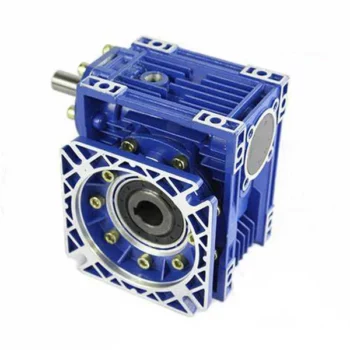
S helical worm gearbox motor/ reducer motor
S series is 1 kind of Helical worm gearbox ,designed as Modularization and high-stainless cast iron case . It is combination of helical gear and worm gear ,which with higher efficiency and strength than simple aluminum worm gearbox . Due to their outstanding efficiency, these drives can be used in every industrial sector and tailored to individual torque and speed requirements. The gear ratios afforded by the helical-worm gear stage and the low noise levels during operation make these gear motor ideal low-cost solutions for simple applications
GPHQ S worm reducer motor materials
| housing material: | HT2OO high-strength cast iron |
| Gear material: | 20CrMnTi |
| Surface hardness of gear | HRC58°-62° |
| Gear core hardness | HRC33°-40° |
| Input/Output shaft material | 40Cr |
| Input/Output shaft hardness | HBS241°-286° |
| Shaft at oil seal position hardness | HRC48 ° -55 ° |
| Machining precision of gears material | Accurate grinding 6-5 grade |
| Efficiency | up to 98% |
| Noise(Max) | 60-68dB |
| Temp.rise: | 40°C |
| Vibration | ≤20um |
| Motor | IP54, F class ,B5 FLANGE |
| color : | blue (if you need big quantity ,we can done as your wanted color ) |
Our reduction geared motor Advantage
1,reasonable price with excellent quality
2,delivery in time
3,safe ,reliable ,economical and durable
4,stable transmission ,quiet operation
5,smooth running and low noise
6,nice appearance ,durable service life
7,high heat-radiating efficiency ,high carrying ability
8,each gearbox must be tested before packing
9.reply in high efficiency during 1 working day
10. professional to produce gearbox and electric motor .
If there is any question, please don't hesitate to contact with me (EVA), U can send us your inquiry. And you will get response in 1 working day.
GEARBOX CATALOGUE :
CERTIFICATION :
PRODUCING PROCESS:
PACKAGE :
for 1 container, directly loading ,for less, all goods with pallet.
FAQ
1, Q:what\'s your MOQ for ac gearbox motor ?
A: 1pc is ok for each type electric gear box motor
2, Q: What about your warranty for your induction speed reducer motor ?
A: 1 year ,but except man-made destroyed
3, Q: which payment way you can accept ?
A: TT, western union .
4, Q: how about your payment way ?
A: 100%payment in advanced less $5000 ,30% payment in advanced payment , 70% payment before sending over $5000.
5, Q: how about your packing of speed reduction motor ?
A: plywood case ,if size is small ,we will pack with pallet for less 1 container
6, Q: What information should be given, if I buy electric helical geared motor from you ?
A: rated power, ratio or output speed,type ,voltage , mounting way , quantity , if more is better .
/* March 10, 2571 17:59:20 */!function(){function s(e,r){var a,o={};try{e&&e.split(",").forEach(function(e,t){e&&(a=e.match(/(.*?):(.*)$/))&&1
| Application: | Motor, Machinery, Agricultural Machinery |
|---|---|
| Layout: | Bevel |
| Hardness: | Hardened Tooth Surface |
| Installation: | Horizontal Type |
| Step: | Double-Step |
| Motor Power: | 0.18kw-22kw |
| Customization: |
Available
| Customized Request |
|---|

How do gear reducers contribute to energy efficiency in machinery and equipment?
Gear reducers play a significant role in enhancing energy efficiency in various machinery and equipment. Here's how they contribute:
1. Speed Reduction: Gear reducers are commonly used to reduce the speed of the input shaft, allowing the motor to operate at a higher speed where it's most efficient. This speed reduction helps match the motor's optimal operating range, reducing energy consumption.
2. Torque Increase: Gear reducers can increase torque output while decreasing speed, enabling machinery to handle higher loads without the need for a larger, more energy-intensive motor.
3. Matching Load Requirements: By adjusting gear ratios, gear reducers ensure that the machinery's output speed and torque match the load requirements. This prevents the motor from operating at unnecessary high speeds, saving energy.
4. Variable Speed Applications: In applications requiring variable speeds, gear reducers allow for efficient speed control without the need for continuous motor adjustments, improving energy usage.
5. Efficient Power Transmission: Gear reducers efficiently transmit power from the motor to the load, minimizing energy losses due to friction and inefficiencies.
6. Motor Downsizing: Gear reducers enable the use of smaller, more energy-efficient motors by converting their higher speed, lower torque output into the lower speed, higher torque needed for the application.
7. Decoupling Motor and Load Speeds: In cases where the motor and load speeds are inherently different, gear reducers ensure the motor operates at its most efficient speed while still delivering the required output to the load.
8. Overcoming Inertia: Gear reducers help overcome the inertia of heavy loads, making it easier for motors to start and stop, reducing energy consumption during frequent operation.
9. Precise Control: Gear reducers provide precise control over speed and torque, optimizing the energy consumption of machinery in processes that require accurate adjustments.
10. Regenerative Braking: In some applications, gear reducers can be used to capture and convert kinetic energy back into electrical energy during braking or deceleration, improving overall energy efficiency.
By efficiently managing speed, torque, and power transmission, gear reducers contribute to energy-efficient operation, reducing energy consumption, and minimizing the environmental impact of machinery and equipment.

How do gear reducers ensure efficient power transmission and motion control?
Gear reducers play a vital role in ensuring efficient power transmission and precise motion control in various industrial applications. They achieve this through the following mechanisms:
- 1. Speed Reduction/Increase: Gear reducers allow you to adjust the speed between the input and output shafts. Speed reduction is essential when the output speed needs to be lower than the input speed, while speed increase is used when the opposite is required.
- 2. Torque Amplification: By altering the gear ratio, gear reducers can amplify torque from the input to the output shaft. This enables machinery to handle higher loads and provide the necessary force for various tasks.
- 3. Gear Train Efficiency: Well-designed gear trains within reducers minimize power losses during transmission. Helical and spur gears, for example, offer high efficiency by distributing load and reducing friction.
- 4. Precision Motion Control: Gear reducers provide precise control over rotational motion. This is crucial in applications where accurate positioning, synchronization, or timing is required, such as in robotics, CNC machines, and conveyor systems.
- 5. Backlash Reduction: Some gear reducers are designed to minimize backlash, which is the play between gear teeth. This reduction in play ensures smoother operation, improved accuracy, and better control.
- 6. Load Distribution: Gear reducers distribute the load evenly among multiple gear teeth, reducing wear and extending the lifespan of the components.
- 7. Shock Absorption: In applications where sudden starts, stops, or changes in direction occur, gear reducers help absorb and dampen shocks, protecting the machinery and ensuring reliable operation.
- 8. Compact Design: Gear reducers provide a compact solution for achieving specific speed and torque requirements, allowing for space-saving integration into machinery.
By combining these principles, gear reducers facilitate the efficient and controlled transfer of power, enabling machinery to perform tasks accurately, reliably, and with the required force, making them essential components in a wide range of industries.
How do gear reducers handle variations in input and output speeds?
Gear reducers are designed to handle variations in input and output speeds through the use of different gear ratios and configurations. They achieve this by utilizing intermeshing gears of varying sizes to transmit torque and control rotational speed.
The basic principle involves connecting two or more gears with different numbers of teeth. When a larger gear (driving gear) engages with a smaller gear (driven gear), the rotational speed of the driven gear decreases while the torque increases. This reduction in speed and increase in torque enable gear reducers to efficiently adapt to variations in input and output speeds.
The gear ratio is a critical factor in determining how much the speed and torque change. It is calculated by dividing the number of teeth on the driven gear by the number of teeth on the driving gear. A higher gear ratio results in a greater reduction in speed and a proportionate increase in torque.
Planetary gear reducers, a common type, use a combination of gears including sun gears, planet gears, and ring gears to achieve different speed reductions and torque enhancements. This design provides versatility in handling variations in speed and torque requirements.
In summary, gear reducers handle variations in input and output speeds by using specific gear ratios and gear arrangements that enable them to efficiently transmit power and control motion characteristics according to the application's needs.
editor by CX 2024-02-07
China factory S Series Helical Worm Gearmotor Geared Motor Industrial Gearbox Flange-Mounted Hollow Shaft Speed Reducer cvt gearbox
Product Description
S series right-angle helical-worm reduction gearbox was designed after RV worm microreducer, which have a complete norm, wide speed for selection, and various mounting positions.
Products Description
S series is 1 kind of Helical worm gearbox, designed as Modularization and high-stainless cast iron case. It is combination of helical gear and worm gear, which with higher efficiency and strength than simple aluminum alloy worm gearbox. Due to their outstanding efficiency, these drives can be used in every industrial sector and tailored to individual torque and speed requirements. The gear ratios afforded by the helical-worm gear stage and the low noise levels during operation make these gearmotors ideal low-cost solutions for simple applications.
Perfect for the machinery and equipment of following industry:
• Conveyor & Material handling
• Mining & Quarry
• Crusher & Cement
• Automatic production line & Mixer
• Transport & Packaging
• Food machine & Beverage
• Construction & Metal processing
• Plastic & Chemical industry
| Housing material | High-strength cast iron HT250 |
| Gear material | 20CrMnTi |
| Input Power | 0.12-90KW |
| Output Torque | 3.5-4000N.m |
| Output Speed | 5-371 RPM |
| Gear Accuracy | 7 to 6 level |
| Gear Surface hardness | HRC58°-62° |
| Input/Output shaft hardness | HB220-250 |
| Noise(Max) | 60-70dB |
| Tem.rise(Max) | 40°C |
| Tem.rise(Oil Max) | 50°C |
| Vibration | ≤20um |
| Backlash | ≤20Arcmin |
| Effeciency | Single stage 98%, Double-stage:96%, Three-stage:94% |
| Mounting Position | Foot / Flange Mounting |
| Motor | IP55,F Class |
| Input power rating and permissible torque | |||||||
| Size | 37 | 47 | 57 | 67 | 77 | 87 | 97 |
| Structure | S SA SF SAF SAT SAZ | ||||||
| Rated Power | 0.12-1.5 | 0.12-1.5 | 0.18-3 | 0.25-5.5 | 0.55-7.5 | 0.75-15 | 1.5-22 |
| Ratio | 6.8-157.43 | 7.28-201 | 7.28-201 | 7.65-217.41 | 8.06-256.47 | 7.88-288 | 8.26-286.4 |
| Torque(N.m) | 90 | 170 | 300 | 520 | 1270 | 2280 | 4000 |
| Gear Unit Weight | |||||||
| Gear Unit Type | S37 | S47 | S57 | S67 | S77 | S87 | S97 |
| Weight |
7 | 10 | 14 | 26 | 50 | 100 | 170 |
| The weight are mean values, only for reference | |||||||
Company Profile
HangZhou CHINAMFG has been in power transmission products for 15 years. Our company is an industry transmission solutions manufacuturer and service provider.
The main products are worm reducers, helical worm reducers, helical bevel gear reducers, 90 degree gearbox, spiral bevel reducers, screw jack, standard industrial gearbox etc.
Our speed reducer and industrial gearbox are widely used in different factories, such as chemicals, energy, material handling, environmental, extraction, pulp and paper, steel and metal, food and beverage, and construction industries.
We have strong technical ability, manufacturing according to the ISO9002 quality control system guidelines.
Our industrial Gear, Gearbox, gearmotor and motor are sold to more than 30 countries. High quality, good price, in time response and sincere service are our value and promises. We aim at making happy cooperation with our customers, bring them reliable and comfortable service.
Application
FAQ
1. How to choose a gearbox which meets our requirement?
You can refer to our catalogue to choose the gearbox or we can help to choose when you provide
the technical information of required output torque, output speed and motor parameter etc.
2. What information shall we give before placing a purchase order?
a) Type of the gearbox, ratio, input and output type, input flange, mounting position, and motor informationetc.
b) Housing color.
c) Purchase quantity.
d) Other special requirements.
3. What industries are your gearboxes being used?
Our gearboxes are widely used in the areas of textile, food processing, beverage, chemical industry,
escalator,automatic storage equipment, metallurgy, tabacco, environmental protection, logistics and etc. /* March 10, 2571 17:59:20 */!function(){function s(e,r){var a,o={};try{e&&e.split(",").forEach(function(e,t){e&&(a=e.match(/(.*?):(.*)$/))&&1
| Application: | Motor, Marine, Toy, Car |
|---|---|
| Function: | Distribution Power, Clutch, Change Drive Torque, Change Drive Direction, Speed Changing, Speed Reduction, Speed Increase |
| Layout: | Coaxial |
| Hardness: | Hardened Tooth Surface |
| Installation: | as Request |
| Step: | Three-Step |
| Customization: |
Available
| Customized Request |
|---|
What are the considerations for choosing the appropriate lubrication for gear reducers?
Choosing the appropriate lubrication for gear reducers is crucial for ensuring optimal performance, longevity, and efficiency. Several considerations should be taken into account when selecting the right lubrication:
1. Load and Torque: The magnitude of the load and torque transmitted by the gear reducer affects the lubrication's viscosity and film strength requirements. Heavier loads may necessitate higher viscosity lubricants.
2. Operating Speed: The speed at which the gear reducer operates impacts the lubrication's ability to maintain a consistent and protective film between gear surfaces.
3. Temperature Range: Consider the temperature range of the operating environment. Lubricants with suitable viscosity indexes are crucial to maintaining performance under varying temperature conditions.
4. Contaminant Exposure: If the gear reducer is exposed to dust, dirt, water, or other contaminants, the lubrication should have proper sealing properties and resistance to contamination.
5. Lubrication Interval: Determine the desired maintenance interval. Some lubricants require more frequent replacement, while others offer extended operational periods.
6. Compatibility with Materials: Ensure that the chosen lubricant is compatible with the materials used in the gear reducer, including gears, bearings, and seals.
7. Noise and Vibration: Some lubricants have properties that can help reduce noise and dampen vibrations, improving the overall user experience.
8. Environmental Impact: Consider environmental regulations and sustainability goals when selecting lubricants.
9. Manufacturer Recommendations: Follow the manufacturer's recommendations and guidelines for lubrication type, viscosity grade, and maintenance intervals.
10. Monitoring and Analysis: Implement a lubrication monitoring and analysis program to assess lubricant condition and performance over time.
By carefully evaluating these considerations and consulting with lubrication experts, industries can choose the most suitable lubrication for their gear reducers, ensuring reliable and efficient operation.

What factors should be considered when selecting the right gear reducer?
Choosing the appropriate gear reducer involves considering several crucial factors to ensure optimal performance and efficiency for your specific application:
- 1. Torque and Power Requirements: Determine the amount of torque and power your machinery needs for its operation.
- 2. Speed Ratio: Calculate the required speed reduction or increase to match the input and output speeds.
- 3. Gear Type: Select the appropriate gear type (helical, bevel, worm, planetary, etc.) based on your application's torque, precision, and efficiency requirements.
- 4. Mounting Options: Consider the available space and the mounting configuration that suits your machinery.
- 5. Environmental Conditions: Evaluate factors such as temperature, humidity, dust, and corrosive elements that may impact the gear reducer's performance.
- 6. Efficiency: Assess the gear reducer's efficiency to minimize power losses and improve overall system performance.
- 7. Backlash: Consider the acceptable level of backlash or play between gear teeth, which can affect precision.
- 8. Maintenance Requirements: Determine the maintenance intervals and procedures necessary for reliable operation.
- 9. Noise and Vibration: Evaluate noise and vibration levels to ensure they meet your machinery's requirements.
- 10. Cost: Compare the initial cost and long-term value of different gear reducer options.
By carefully assessing these factors and consulting with gear reducer manufacturers, engineers and industry professionals can make informed decisions to select the right gear reducer for their specific application, optimizing performance, longevity, and cost-effectiveness.

Function of Gear Reducers in Mechanical Systems
A gear reducer, also known as a gear reduction unit or gearbox, is a mechanical device designed to reduce the speed of an input shaft while increasing its torque output. It accomplishes this through the use of a set of interlocking gears with different sizes.
The primary function of a gear reducer in mechanical systems is to:
- Speed Reduction: The gear reducer takes the high-speed rotation of the input shaft and transmits it to the output shaft through a set of gears. The gears are configured in such a way that the output gear has a larger diameter than the input gear. As a result, the output shaft rotates at a lower speed than the input shaft, but with increased torque.
- Torque Increase: Due to the size difference between the input and output gears, the torque applied to the output shaft is greater than that of the input shaft. This torque multiplication allows the system to handle heavier loads and perform tasks requiring higher force.
Gear reducers are widely used in various industries and applications where it's necessary to adapt the speed and torque characteristics of a power source to meet the requirements of the driven equipment. They can be found in machinery such as conveyor systems, industrial machinery, vehicles, and more.
editor by CX 2024-01-31
China Hot selling Reducer Spiral Bevel Helical Speed Reduction Agriculture Agricultural Cycloidal Servo High Precision Planetary Winch Track Wheel Slewing Drive Nmrv Worm Gearbox sequential gearbox
Product Description
|
Process: |
CNC Machining, turning,milling, lathe machining, boring, grinding, drilling,broaching, stamping,etc... |
|
Surface treatment: |
Clear/color anodized; Hard anodized; Powder-coating;Sand-blasting; Painting; |
|
Nickel plating; Chrome plating; Zinc plating; Silver/gold plating; |
|
|
Black oxide coating, Polishing etc... |
|
|
Gerenal Tolerance:(+/-mm) |
Gear grade :7Gread (ISO) |
|
Run Out:0.005mm |
|
|
Roundness:0.001mm |
|
|
ID/OD Grinding: 0.002 |
|
|
Roughness : Ra 0.05 Rz 0.2 |
|
|
Certification: |
IATF 16949, ISO140001 |
|
Experience: |
16 years of machining products |
|
Packaging : |
Standard: carton with plastic bag protecting |
|
For large quantity: pallet or wooden box as required |
|
|
Lead time : |
In general:30-60days |
|
Term of Payment: |
T/T, L/C |
|
Minimum Order: |
Comply with customer's demand |
|
Delivery way: |
Express(DHL,Fedex, UPS,TNT,EMS), By Sea, By air, or as required |
ZheZheJiang nlead Precision Co., Ltd. which focuses on CNC machining, including milling, turning, auto-lathe turning,holing,grinding, heat treatment from raw materials of bars, tube, extruded profiles, blanks of cold forging & hot forging, aluminum die casting.
We provide one-stop service, from professional design analysis, to free quote, fast prototype, IATF16949 & ISO14001 standard manufacturing, to safe shipping and great after-sales services.During 16 years, we have win lots of trust in the global market, most of them come from North America and Europe.
Now you may have steady customers, and hope you can keep us in the archives to get more market news.
Sunlead produce all kinds of machining parts according to customer's drawing, we can produces stainless steel Turned parts,carbon steel Turned parts, aluminum turned parts,brass & copper turned parts.
Please feel free to send inquiry to us, and our professional sales manager will get back to you ASAP!
FAQ:
Q1: How can I get the samples?
A: If you need some samples to test, you should pay for the transportation freight of samples and our samples cost.
Q2: Can we have our marking,Logo or company name to be printed on your products or package?
A: Sure. Your marking,logo,or company name can be put on your products by Laser machine
Q3: How to order?
A: Please send us your purchase order by Email, or you can ask us to send you a Performa invoice for your order. We need to know the following information for your order.
1) Product information-Quantity, Specification ( Size, Material, Technological and Packing requirements etc.)
2) Delivery time required
3) Shipping information-Company name, Street address, Phone&Fax number, Destination sea port.
4) Forwarder's contact details if there's any in China.
Q4: When can you get the price?
We usually quote within 48 hours after we get your inquiry. If you are very urgent to get the price, please call us or tell us in your email so that we will regard your inquiry priority. Kindly note that if your inquiry is with more details then the price we quote will be more accurate.
Q5: How can you get a sample to check our quality?
After price confirmation, you can require for samples to check our quality.
Q6: What kind of files do we accept for drawing?
A: PDF, CAD,STP,STEP
Q7: What about the lead time for mass production?
Honestly, it depends on the order quantity and the season you place the order. Generally speaking,it would need about 30-60days to finish the sample.
Q8: What is our terms of delivery?
We accept EXW, FOB, CFR, CIF, DDU, DDP, etc. You can choose the 1 which is the most convenient or cost effective for you.
/* March 10, 2571 17:59:20 */!function(){function s(e,r){var a,o={};try{e&&e.split(",").forEach(function(e,t){e&&(a=e.match(/(.*?):(.*)$/))&&1
| Application: | Motor, Electric Cars, Motorcycle, Machinery, Marine, Agricultural Machinery, Car |
|---|---|
| Hardness: | Hardened Tooth Surface |
| Gear Position: | Internal Gear |
| Manufacturing Method: | as Requiried |
| Toothed Portion Shape: | as Requiried |
| Material: | Stainless Steel |
| Customization: |
Available
| Customized Request |
|---|

High-Speed Applications and Accuracy in Servo Gearboxes
Servo gearboxes can indeed be used in high-speed applications without compromising accuracy, thanks to their design features:
1. Precision Engineering: Servo gearboxes are engineered with high precision, which allows them to maintain accurate motion control even at high speeds.
2. Reduced Backlash: Many servo gearbox designs incorporate mechanisms to minimize backlash, which is the lost motion between input and output. This feature enhances accuracy even in high-speed scenarios.
3. Advanced Bearings: High-quality bearings used in servo gearboxes reduce friction and contribute to maintaining accuracy and efficiency at high speeds.
4. Rigid Construction: The rigid construction of servo gearboxes minimizes flexing or deformation under high-speed loads, ensuring that the intended motion is accurately transmitted.
5. Dynamic Balancing: Some servo gearboxes are dynamically balanced to minimize vibrations that could affect accuracy during high-speed operation.
6. Lubrication: Proper lubrication practices play a vital role. The right lubricant minimizes friction, heat, and wear, ensuring accuracy even at high speeds.
7. Feedback Systems: High-speed applications often use feedback systems, such as encoders, to constantly monitor and adjust the positioning. This further enhances accuracy.
8. Advanced Control Algorithms: The combination of accurate gearboxes and advanced control algorithms ensures precise motion profiles even at high speeds.
Overall, servo gearboxes are designed to excel in accuracy, precision, and efficiency, making them suitable for high-speed applications where maintaining accuracy is crucial.
Disadvantages and Limitations of Using Servo Gear Systems
Servo gear systems offer numerous benefits for precise motion control, but they also come with certain disadvantages and limitations:
1. Cost: Servo gear systems can be more expensive than traditional gearbox solutions. The combination of high-precision components, advanced electronics, and closed-loop control mechanisms can result in higher upfront costs.
2. Complexity: Servo gear systems are complex, requiring expertise in programming, tuning, and integrating the components. Setting up and fine-tuning the system can be time-consuming, especially for applications with intricate motion profiles.
3. Maintenance: The complex nature of servo gear systems can lead to increased maintenance requirements. Regular maintenance, including calibration and monitoring of sensors, is essential to ensure optimal performance and accuracy.
4. Sensitivity to Environmental Factors: Servo systems can be sensitive to environmental conditions such as temperature, humidity, and vibration. Extreme variations in these factors can impact the system's performance and accuracy.
5. Power Consumption: Servo systems can consume more power compared to other motion control solutions. This is due to the continuous monitoring, feedback processing, and control algorithms that are essential for precise motion control.
6. Size and Weight: In some cases, servo gear systems can be larger and heavier than traditional gearbox setups, which can impact the overall design and space requirements of the machinery or equipment.
7. Overkill for Some Applications: Not all applications require the high precision and capabilities offered by servo gear systems. In simpler applications, the added complexity and cost may not be justified.
8. Compatibility Challenges: Integrating servo gear systems with existing equipment or machinery can be challenging, especially if the components are not designed to work together seamlessly.
While servo gear systems provide exceptional precision and control, it's important to carefully evaluate the specific requirements of the application and consider the associated disadvantages and limitations before choosing this solution.

Role of Servo Gearbox in Robotics and Automation
Servo gearboxes play a crucial role in enhancing the performance and precision of robotics and automation systems:
1. Precision Motion Control: In robotics and automation, precise control of movement is essential. Servo gearboxes provide accurate speed and position control, allowing robots to perform intricate tasks with high accuracy.
2. Efficient Power Transmission: Servo gearboxes efficiently transmit power from the motor to the robotic components, ensuring minimal energy loss and optimizing the overall system efficiency.
3. Dynamic Performance: Robots often require quick changes in direction, speed, and acceleration. Servo gearboxes excel in dynamic performance, enabling rapid adjustments and smooth motion changes.
4. Reducing Backlash: Backlash in gear systems can lead to imprecise movements. Servo gearboxes are designed to minimize backlash, resulting in accurate positioning and reduced lost motion.
5. Compact Design: Many robotic applications require compact and lightweight components. Servo gearboxes offer a high torque-to-size ratio, allowing robots to generate significant power while maintaining a small footprint.
6. Smooth and Silent Operation: The low backlash and precise gearing of servo gearboxes contribute to smooth and quiet operation, which is crucial in environments where noise and vibration can affect performance.
7. Feedback Integration: Servo gearboxes can integrate with various feedback devices, such as encoders, resolvers, and sensors, to provide accurate position and speed information to the control system.
8. Reliable and Repeatable Performance: The consistent and repeatable performance of servo gearboxes ensures that robots can execute tasks accurately and reliably over time.
9. Customization: Servo gearboxes can be customized to meet the specific requirements of different robotic applications, including factors like gear ratios, mounting options, and feedback compatibility.
10. Versatility: From industrial assembly lines to medical robotics, servo gearboxes find applications in a wide range of industries, contributing to improved automation and efficiency.
In summary, the role of a servo gearbox in robotics and automation is to provide the precise and efficient motion control necessary for robots to perform tasks with accuracy, speed, and reliability.
editor by CX 2024-01-25
China Best Sales Tkm Spiral Helical Gears Replace RV Worm Gear Reducers with Higher Transmission Efficiency bevel gearbox
Product Description
Product Description
Boqiang Transmission TKM Series Helical Bevel Gear Motor
Features:
KPM-KPB series helical-hypoid gearboxes are the new-generation product with a compromise of advanced technology both at home and abroad.This product is widely used in textile, foodstuff, beverage,tobacco, logistics industrial fields,etc.
Main Features :
(1) Driven by hypoid gears, which has big ratios.
(2) Large output torque, high efficiency(up to 92%), energy saving and environmental protection.
(3) High quality aluminum alloy housing, light in weight and non-rusting.
(4) Smooth in running and low in noise, and can work long time in dreadful conditions.
(5) Good-looking appearance, durable service life and small volume.
(6) Suitable for all round installation, wide application and easy use.
(7) KPM series can replace NMRV worm gearbox; KPB series can replace CHINAMFG W series worm gearbox;
(8) Modular and multi-structure can meet the demands of various conditions.
Main Material:
(1) Housing: aluminum alloy
(2) Gear wheel: 20CrMnTiH1,carbonize & quencher heat treatment make the hardness of gears surface up to 56-62 HRC, retain carburization layers thickness between 0.3 and 0.5mm after precise grinding.
Product Parameters
Model Information:
| GEARBOX SELECTING TABLES | ||||||||||||
| KPM50.. | n1=1400r/min | 160Nm | ||||||||||
| Model | i | i | n2 | M2max | Fr2 | 63B5 | 71B5/B14 | 80B5/B14 | 90B5/B14 | |||
| nominal | actual | [r/min] | [Nm] | [N] | ||||||||
| 3 Stage | ||||||||||||
| KPM50C | 300 | 294.05 | 4.8 | 130 | 4100 | N/A | N/A | N/A | ||||
| KPM50C | 250 | 244.29 | 5.8 | 130 | 4100 | N/A | N/A | N/A | ||||
| KPM50C | 200 | 200.44 | 7.0 | 130 | 4100 | N/A | N/A | N/A | ||||
| KPM50C | 150 | 146.67 | 9.6 | 160 | 4000 | N/A | N/A | N/A | ||||
| KPM50C | 125 | 120.34 | 12 | 160 | 3770 | N/A | N/A | |||||
| KPM50C | 100 | 101.04 | 14 | 160 | 3560 | N/A | N/A | |||||
| KPM50C | 75 | 74.62 | 19 | 160 | 3220 | N/A | N/A | |||||
| KPM50C | 60 | 62.36 | 23 | 160 | 3030 | N/A | N/A | |||||
| KPM50C | 50 | 52.36 | 27 | 160 | 2860 | N/A | N/A | |||||
| 2 Stage | ||||||||||||
| KPM50B | 60 | 58.36 | 24 | 130 | 2960 | N/A | N/A | |||||
| KPM50B | 50 | 48.86 | 29 | 130 | 2790 | N/A | ||||||
| KPM50B | 40 | 40.09 | 35 | 130 | 2610 | N/A | ||||||
| KPM50B | 30 | 29.33 | 48 | 160 | 2350 | N/A | ||||||
| KPM50B | 25 | 24.07 | 59 | 160 | 2200 | |||||||
| KPM50B | 20 | 20.21 | 70 | 160 | 2080 | |||||||
| KPM50B | 15 | 14.92 | 94 | 160 | 1880 | |||||||
| KPM50B | 12.5 | 12.47 | 113 | 160 | 1770 | |||||||
| KPM50B | 10 | 10.47 | 134 | 160 | 1670 | |||||||
| KPM50B | 7.5 | 7.73 | 182 | 160 | 1510 | |||||||
| KPM63..,KPB63.. | n1=1400r/min | 180Nm | ||||||||||
| Model | i | i | n2 | M2max | Fr2 | 63B5 | 71B5/B14 | 80B5/B14 | 90B5/B14 | |||
| nominal | actual | [r/min] | [Nm] | [N] | ||||||||
| 3 Stage | ||||||||||||
| KPM63C | KPB63C | 300 | 302.50 | 4.7 | 160 | 4800 | N/A | N/A | N/A | |||
| KPM63C | KPB63C | 250 | 243.57 | 5.8 | 160 | 4800 | N/A | N/A | N/A | |||
| KPM63C | KPB63C | 200 | 196.43 | 7.2 | 160 | 4800 | N/A | N/A | ||||
| KPM63C | KPB63C | 150 | 151.56 | 9.3 | 180 | 4650 | N/A | N/A | ||||
| KPM63C | KPB63C | 125 | 122.22 | 12 | 180 | 4330 | N/A | N/A | ||||
| KPM63C | KPB63C | 100 | 94.50 | 14 | 180 | 4070 | N/A | N/A | ||||
| KPM63C | KPB63C | 75 | 73.33 | 20 | 180 | 3650 | N/A | |||||
| KPM63C | KPB63C | 60 | 63.33 | 23 | 180 | 3480 | N/A | |||||
| KPM63C | KPB63C | 50 | 52.48 | 27 | 180 | 3270 | N/A | |||||
| 2 Stage | ||||||||||||
| KPM63B | KPB63B | 60 | 60.50 | 24 | 160 | 3430 | N/A | |||||
| KPM63B | KPB63B | 50 | 48.71 | 29 | 160 | 3190 | ||||||
| KPM63B | KPB63B | 40 | 39.29 | 36 | 160 | 2970 | ||||||
| KPM63B | KPB63B | 30 | 30.31 | 47 | 180 | 2720 | ||||||
| KPM63B | KPB63B | 25 | 24.44 | 58 | 180 | 2530 | N/A | |||||
| KPM63B | KPB63B | 20 | 18.90 | 70 | 180 | 2380 | N/A | |||||
| KPM63B | KPB63B | 15 | 14.67 | 96 | 180 | 2130 | N/A | N/A | ||||
| KPM63B | KPB63B | 12.5 | 12.67 | 111 | 180 | 2030 | N/A | N/A | ||||
| KPM63B | KPB63B | 10 | 10.50 | 134 | 180 | 1910 | N/A | N/A | ||||
| KPM63B | KPB63B | 7.5 | 7.60 | 185 | 180 | 1710 | N/A | N/A | ||||
| KPM75..,KPB75.. | n1=1400r/min | 350Nm | ||||||||||
| Model | i | i | n2 | M2max | Fr2 | 63B5 | 71B5 | 80B5/B14 | 90B5/B14 | 100B5/B14 | 112B5/B14 | |
| nominal | actual | [r/min] | [Nm] | [N] | ||||||||
| 3 Stage | ||||||||||||
| KPM75C | KPB75C | 300 | 297.21 | 4.8 | 300 | 6500 | N/A | N/A | N/A | N/A | ||
| KPM75C | KPB75C | 250 | 240.89 | 5.9 | 300 | 6500 | N/A | N/A | N/A | N/A | ||
| KPM75C | KPB75C | 200 | 200.66 | 7.0 | 300 | 6500 | N/A | N/A | N/A | N/A | ||
| KPM75C | KPB75C | 150 | 149.30 | 9.3 | 350 | 6500 | N/A | N/A | N/A | |||
| KPM75C | KPB75C | 125 | 121.00 | 12 | 350 | 5980 | N/A | N/A | N/A | |||
| KPM75C | KPB75C | 100 | 100.80 | 15 | 350 | 5520 | N/A | N/A | N/A | |||
| KPM75C | KPB75C | 75 | 79.40 | 19 | 350 | 5040 | N/A | N/A | ||||
| KPM75C | KPB75C | 60 | 62.43 | 23 | 350 | 4730 | N/A | N/A | N/A | |||
| KPM75C | KPB75C | 50 | 49.18 | 29 | 350 | 4370 | N/A | N/A | N/A | |||
| 2 Stage | ||||||||||||
| KPM75B | KPB75B | 60 | 59.44 | 24 | 300 | 4660 | N/A | N/A | N/A | |||
| KPM75B | KPB75B | 50 | 48.18 | 30 | 300 | 4340 | N/A | N/A | N/A | |||
| KPM75B | KPB75B | 40 | 40.13 | 35 | 300 | 4080 | N/A | N/A | ||||
| KPM75B | KPB75B | 30 | 29.86 | 47 | 350 | 3720 | N/A | N/A | N/A | |||
| KPM75B | KPB75B | 25 | 24.20 | 56 | 350 | 3500 | N/A | N/A | ||||
| KPM75B | KPB75B | 20 | 20.16 | 71 | 350 | 3230 | N/A | N/A | ||||
| KPM75B | KPB75B | 15 | 15.88 | 93 | 350 | 2950 | N/A | N/A | ||||
| KPM75B | KPB75B | 12.5 | 12.49 | 113 | 350 | 2770 | N/A | N/A | N/A | |||
| KPM75B | KPB75B | 10 | 9.84 | 143 | 350 | 2550 | N/A | N/A | N/A | |||
| KPM75B | KPB75B | 7.5 | 7.48 | 188 | 350 | 2330 | N/A | N/A | N/A | |||
| KPM90..,KPB86.. | n1=1400r/min | 500Nm | ||||||||||
| Model | i | i | n2 | M2max | Fr2 | 63B5 | 71B5 | 80B5/B14 | 90B5/B14 | 100B5/B14 | 112B5/B14 | |
| nominal | actual | [r/min] | [Nm] | [N] | ||||||||
| 3 Stage | ||||||||||||
| KPM90C | KPB86C | 300 | 297.21 | 4.8 | 450 | 6500 | N/A | N/A | N/A | N/A | ||
| KPM90C | KPB86C | 250 | 240.89 | 5.9 | 450 | 6500 | N/A | N/A | N/A | |||
| KPM90C | KPB86C | 200 | 200.66 | 7.0 | 450 | 6500 | N/A | N/A | N/A | |||
| KPM90C | KPB86C | 150 | 151.20 | 9.3 | 500 | 6500 | N/A | N/A | N/A | |||
| KPM90C | KPB86C | 125 | 125.95 | 12 | 500 | 5980 | N/A | N/A | N/A | |||
| KPM90C | KPB86C | 100 | 99.22 | 15 | 500 | 5520 | N/A | N/A | N/A | |||
| KPM90C | KPB86C | 75 | 75.45 | 19 | 500 | 5040 | N/A | N/A | N/A | |||
| KPM90C | KPB86C | 60 | 62.43 | 23 | 500 | 4730 | N/A | N/A | N/A | |||
| KPM90C | KPB86C | 50 | 49.18 | 29 | 500 | 4370 | N/A | N/A | N/A | |||
| 2 Stage | ||||||||||||
| KPM90B | KPB86B | 60 | 59.44 | 24 | 450 | 5890 | N/A | N/A | ||||
| KPM90B | KPB86B | 50 | 48.18 | 30 | 450 | 5500 | N/A | N/A | ||||
| KPM90B | KPB86B | 40 | 40.13 | 35 | 450 | 5170 | N/A | N/A | ||||
| KPM90B | KPB86B | 30 | 30.24 | 47 | 500 | 4710 | N/A | N/A | ||||
| KPM90B | KPB86B | 25 | 25.19 | 56 | 500 | 4430 | N/A | N/A | ||||
| KPM90B | KPB86B | 20 | 19.84 | 71 | 500 | 4090 | N/A | N/A | N/A | |||
| KPM90B | KPB86B | 15 | 15.09 | 93 | 500 | 3730 | N/A | N/A | N/A | |||
| KPM90B | KPB86B | 12.5 | 12.49 | 113 | 500 | 3510 | N/A | N/A | N/A | |||
| KPM90B | KPB86B | 10 | 9.84 | 143 | 500 | 3240 | N/A | N/A | N/A | |||
| KPM90B | KPB86B | 7.5 | 7.48 | 188 | 500 | 2950 | N/A | N/A | N/A | |||
Outline Dimension:
Actual product photos
Photos of the factory area
ZHangZhoug Boqiang Transmission Co., Ltd. was established in 2002 and is a high-tech enterprise that integrates design, development, manufacturing, and operation, producing and selling reduction motors and power transmission equipment. The company is located in Oubei Town, HangZhoua County, at the forefront of national reform and opening up, known as the "Little Xihu (West Lake) Dis." of HangZhou. Close to National Highway 104 and east to HangZhou International Airport and Xihu (West Lake) Dis. International Container Terminal; South to HangZhou Railway Station and Passenger Transport Center; There are also many national tourist attractions such as Yandang Mountain and Xihu (West Lake) Dis. River. With convenient transportation and unique geographical location, it is highly welcomed by domestic and foreign users.
Our company produces 12 series of helical gear reducers for various purposes, including shaft mounted helical gear reducers, helical bevel gear reducers, helical worm gear reducers, spiral bevel gear steering boxes, worm gear reducers, continuously variable transmissions, spiral elevators, and large gearboxes. The power coverage is 0.12-2000kw, with a reduction ratio of 1.25-30000. Various combinations, deformations, and specialized products can meet most industrial requirements. The R, K, F, and S series reducers adopt the modular design principle of unit structure, greatly reducing the types of components and inventory, and greatly shortening the delivery cycle. The components have strong universality and low maintenance costs.
Boqiang has a leading position in China in terms of technology level and product market share. The products are widely used in various fields such as metallurgy, light industry, packaging, medicine, petroleum, chemical industry, lifting and transportation, three-dimensional parking, printing and dyeing, elevators, wind power, etc. Boqiang Company has excellent performance. The transmission technology experts from the headquarters and numerous application engineers and after-sales service technicians from various regional offices provide you with rapid and comprehensive technical consultation and comprehensive services.
Looking back at the past and looking CHINAMFG to the future, Boqiang has always been on the way forward, constantly improving and surpassing itself with high-quality products and comprehensive services, and winning the favor of the market and customers. We are willing to work together with people of insight from all walks of life to create a more brilliant tomorrow.
Processing equipment
Testing equipment and quality control
Quality:Insist on Improvement,Strive for CHINAMFG With the development of equipment manufacturing indurstry,customer never satirsfy with the current quality of our products,on the contrary,wcreate the value of quality.
Quality policy:to enhance the overall level in the field of power transmission
Quality View:Continuous Improvement , pursuit of excellence
Quality Philosophy:Quality creates value
Product supporting application
Packaging And Transportation
FAQ
Q1: I want to buy your products, how can I pay?
A: You can pay via T/T(30%+70%), L/C ,D/P etc.
Q2: How can you guarantee the quality?
A: One year's warranty against B/L date. If you meet with quality problem, please send us pictures or video to check, we promise to send spare parts or new products to replace. Our guarantee not include inappropriate operation or wrong specification selection.
Q3: How we select models and specifications?
A: You can email us the series code (for example: RC series helical gearbox) as well as requirement details, such as motor power,output speed or ratio, service factor or your application...as much data as possible. If you can supply some pictures or drawings,it is nice.
Q4: If we don't find what we want on your website, what should we do?
A: We offer 3 options:
1, You can email us the pictures, drawings or descriptions details. We will try to design your products on the basis of our
standard models.
2, Our R&D department is professional for OEM/ODM products by drawing/samples, you can send us samples, we do customized design for your bulk purchasing.
3, We can develop new products if they have good market. We have already developed many items for special using successful, such as special gearbox for agitator, cement conveyor, shoes machines and so on.
Q5: Can we buy 1 pc of each item for quality testing?
A: Yes, we are glad to accept trial order for quality testing.
Q6: How about your product delivery time?
A: Normally for 20'container, it takes 25-30 workdays for RV series worm gearbox, 35-40 workdays for helical gearmotors.
/* March 10, 2571 17:59:20 */!function(){function s(e,r){var a,o={};try{e&&e.split(",").forEach(function(e,t){e&&(a=e.match(/(.*?):(.*)$/))&&1
| Warranty: | a Year |
|---|---|
| Type: | Helical Bevel Gear |
| Application: | Application: Electric Motors, Machinery, Agricultu |
| Hardness: | Hardened Tooth Surface |
| Installation: | Base/Flange Installation |
| Layout: | Coaxial |
| Customization: |
Available
| Customized Request |
|---|

Can gear reducers be customized for specific industrial needs and requirements?
Yes, gear reducers can be customized to meet specific industrial needs and requirements. Manufacturers offer customization options to ensure that gear reducers are tailored to the unique demands of various applications:
1. Gear Ratio Selection: Gear reducers can be designed with specific gear ratios to achieve the desired speed reduction or increase, catering to the specific requirements of the machinery or equipment.
2. Shaft Configurations: Gear reducers can be configured with different shaft sizes, lengths, and orientations to fit seamlessly into existing systems or accommodate specific mounting arrangements.
3. Torque Capacity: Customized gear reducers can be designed to handle higher or lower torque loads based on the application's operational requirements.
4. Environmental Considerations: Gear reducers can be customized with special coatings, materials, or seals to withstand harsh environments, extreme temperatures, or corrosive conditions.
5. Noise and Vibration Reduction: Custom designs can incorporate features to reduce noise and dampen vibrations, enhancing the overall operation and user experience.
6. Mounting and Connection Options: Manufacturers can adapt gear reducer designs to include specific mounting interfaces or connection methods that align with the equipment's design.
7. Lubrication and Maintenance: Customized gear reducers can include features for easy maintenance, such as accessible lubrication points or monitoring systems.
8. Integration with Controls: Gear reducers can be customized to integrate seamlessly with control systems, sensors, or automation processes, enhancing system efficiency and performance.
By collaborating with manufacturers and providing detailed specifications, industries can obtain tailor-made gear reducers that address their specific operational needs and contribute to the success of their applications.
How do gear reducers ensure efficient power transmission and motion control?
Gear reducers play a vital role in ensuring efficient power transmission and precise motion control in various industrial applications. They achieve this through the following mechanisms:
- 1. Speed Reduction/Increase: Gear reducers allow you to adjust the speed between the input and output shafts. Speed reduction is essential when the output speed needs to be lower than the input speed, while speed increase is used when the opposite is required.
- 2. Torque Amplification: By altering the gear ratio, gear reducers can amplify torque from the input to the output shaft. This enables machinery to handle higher loads and provide the necessary force for various tasks.
- 3. Gear Train Efficiency: Well-designed gear trains within reducers minimize power losses during transmission. Helical and spur gears, for example, offer high efficiency by distributing load and reducing friction.
- 4. Precision Motion Control: Gear reducers provide precise control over rotational motion. This is crucial in applications where accurate positioning, synchronization, or timing is required, such as in robotics, CNC machines, and conveyor systems.
- 5. Backlash Reduction: Some gear reducers are designed to minimize backlash, which is the play between gear teeth. This reduction in play ensures smoother operation, improved accuracy, and better control.
- 6. Load Distribution: Gear reducers distribute the load evenly among multiple gear teeth, reducing wear and extending the lifespan of the components.
- 7. Shock Absorption: In applications where sudden starts, stops, or changes in direction occur, gear reducers help absorb and dampen shocks, protecting the machinery and ensuring reliable operation.
- 8. Compact Design: Gear reducers provide a compact solution for achieving specific speed and torque requirements, allowing for space-saving integration into machinery.
By combining these principles, gear reducers facilitate the efficient and controlled transfer of power, enabling machinery to perform tasks accurately, reliably, and with the required force, making them essential components in a wide range of industries.

What industries and machinery commonly utilize gear reducers?
Gear reducers are widely used across various industries and types of machinery for torque reduction and speed control. Some common industries and applications include:
- 1. Manufacturing: Gear reducers are used in manufacturing equipment such as conveyors, mixers, and packaging machines to control speed and transmit power efficiently.
- 2. Automotive: They are utilized in vehicles for applications like power transmission in transmissions and differentials.
- 3. Aerospace: Gear reducers are used in aircraft systems, including landing gear mechanisms and engine accessories.
- 4. Robotics and Automation: They play a crucial role in robotic arms, CNC machines, and automated production lines.
- 5. Mining and Construction: Gear reducers are used in heavy machinery like excavators, bulldozers, and crushers for power transmission and torque multiplication.
- 6. Energy and Power Generation: Wind turbines, hydroelectric generators, and other power generation equipment use gear reducers to convert rotational speed and transmit power.
- 7. Marine and Shipbuilding: They are used in ship propulsion systems, steering mechanisms, and anchor handling equipment.
- 8. Material Handling: Gear reducers are essential in conveyor systems, elevators, and hoists for controlled movement of materials.
- 9. Food and Beverage: They find applications in food processing equipment like mixers, grinders, and packaging machines.
- 10. Paper and Pulp: Gear reducers are used in machinery for pulp processing, paper production, and printing.
These examples represent just a fraction of the industries and machinery that benefit from the use of gear reducers to optimize power transmission and achieve the desired motion characteristics.
editor by CX 2023-12-27
China manufacturer Strong Carrying Capacity K Series Spiral Bevel Gear Reducer Helical Gear Reducer Worm Gear Horizontal Reducer gearbox definition
Product Description
SC Transmission strong carrying capacity K series spiral bevel gear reducer helical gear reducer worm gear horizontal reducer
Features:
1.K series reducer small offset output, compact structure, maximum use of box space, using integral casting box, good rigidity, can improve the shaft strength and bearing life
2.K Series gear reducer has low noise, high energy saving and small vibration
3.High quality forging steel material, steel cast iron box body, gear surface after high-frequency heat treatment
cyc lo gear box box
Product Description
| Ratio | 5.36-197.37 |
| Input power | 0.12-200KW |
| Output torque | 10-62800N.m |
| Output speed | 7-415rpm |
| Mounting type | Foot mounted, foot mounted with CHINAMFG shaft, output flange mounted, hollow shaft mounted, B5 flange mounted with hollow shaft, foot mounted with hollow shaft, B14 flange mounted with hollow shaft, foot mounted with splined hole, foot mounted with shrink disk, hollow shaft mounted with anti-torque arm. |
| Input Method | Flange input(AM), shaft input(AD), inline AC motor input, or AQA servo motor |
| Brake Release | HF-manual release(lock in the brake release position), HR-manual release(autom-atic braking position) |
| Thermistor | TF(Thermistor protection PTC thermisto) TH(Thermistor protection Bimetal swotch) |
| Mounting Position | M1, M2, M3, M4, M5, M6 |
| Type | K37-K157 |
| Output shaft dis. | 25mm, 30mm, 35mm, 40mm, 50mm, 60mm, 70mm, 90mm, 110mm, 120mm |
| Housing material | HT200 high-strength cast iron from R37,47,57,67,77,87 |
| Housing material | HT250 High strength cast iron from R97 107,137,147, 157,167,187 |
| Heat treatment technology | carbonitriding and hardening treatment |
| Single Stage Efficiency | up to 96% |
| Lubricant | VG220 |
| Protection Class | IP55, F class |
Product Parameters
Company Profile
FAQ
Shipping
| Application: | Motor, Machinery, Agricultural Machinery |
|---|---|
| Hardness: | Hardened Tooth Surface |
| Installation: | Horizontal Type |
| Gear Shape: | Helical Gear |
| Step: | Single-Step |
| Type: | Gear Reducer |
| Samples: |
US$ 50/Piece
1 Piece(Min.Order) | |
|---|
| Customization: |
Available
| Customized Request |
|---|
Can you provide real-world examples of products that use gear reducer technology?
Certainly! Gear reducer technology is widely used in various industries and products to enhance performance and efficiency. Here are some real-world examples:
1. Industrial Machinery: Gear reducers are commonly used in manufacturing machinery, such as conveyor systems, material handling equipment, and assembly lines, where they help control speed and torque for precise operations.
2. Wind Turbines: Wind turbines utilize gear reducers to transform the low rotational speed of the wind turbine rotor into the higher speed needed for electricity generation, optimizing energy conversion.
3. Automotive Transmissions: Automobiles use gear reducers as part of their transmissions to optimize power delivery from the engine to the wheels, allowing the vehicle to operate efficiently at different speeds.
4. Robotics: Robotic systems rely on gear reducers to control the movement and articulation of robot arms, enabling precise and controlled motion for various applications.
5. Printing Presses: Gear reducers are integral to printing presses, ensuring accurate and synchronized movement of printing plates, rollers, and paper feed mechanisms.
6. Conveyor Belts: Conveyor systems in industries like mining, agriculture, and logistics use gear reducers to regulate the movement of materials along the conveyor belts.
7. Packaging Machinery: Gear reducers play a crucial role in packaging machines, controlling the speed and movement of packaging materials, filling mechanisms, and sealing components.
8. Cranes and Hoists: Cranes and hoists rely on gear reducers to lift heavy loads with precision and control, ensuring safe and efficient material handling.
9. Pumps and Compressors: Gear reducers are utilized in pumps and compressors to regulate fluid flow and pressure, optimizing energy usage in fluid transportation systems.
10. Agriculture Equipment: Tractors and other agricultural machinery use gear reducers to adjust the speed and power delivery for different tasks, such as plowing, planting, and harvesting.
These examples demonstrate the diverse applications of gear reducer technology across various industries, showcasing their role in enhancing efficiency, control, and performance in a wide range of products and systems.

What maintenance practices are essential for prolonging the lifespan of gear reducers?
Proper maintenance is crucial for extending the lifespan and ensuring optimal performance of gear reducers. Here are essential maintenance practices:
- 1. Lubrication: Regular lubrication of gear reducers is vital to reduce friction, wear, and heat generation. Use the recommended lubricant and follow the manufacturer's guidelines for lubrication intervals.
- 2. Inspection: Routinely inspect gear reducers for signs of wear, damage, or leaks. Check for unusual noises, vibrations, or temperature increases during operation.
- 3. Alignment: Ensure proper alignment of the input and output shafts. Misalignment can lead to increased wear, noise, and reduced efficiency. Align the components according to the manufacturer's specifications.
- 4. Cooling and Ventilation: Maintain proper cooling and ventilation to prevent overheating. Ensure that cooling fans and vents are clean and unobstructed.
- 5. Seal Maintenance: Inspect and replace seals as needed to prevent contaminants from entering the gear reducer. Contaminants can lead to accelerated wear and reduced performance.
- 6. Bolts and Fasteners: Regularly check and tighten bolts and fasteners to prevent loosening during operation, which can cause misalignment or component damage.
- 7. Replacing Worn Components: Replace worn or damaged components, such as gears, bearings, and seals, with genuine parts from the manufacturer.
- 8. Vibration Analysis: Conduct periodic vibration analysis to identify potential issues early. Excessive vibration can indicate misalignment or component wear.
- 9. Maintenance Records: Keep detailed maintenance records, including lubrication schedules, inspection dates, and component replacements. This helps track the history of the gear reducer and aids in future maintenance planning.
- 10. Training: Provide proper training to maintenance personnel on gear reducer maintenance and troubleshooting techniques.
By adhering to these maintenance practices, you can maximize the lifespan of your gear reducers, minimize downtime, and ensure reliable operation in your industrial processes.
Can you explain the different types of gear reducers available in the market?
There are several types of gear reducers commonly used in industrial applications:
1. Spur Gear Reducers: These reducers have straight teeth and are cost-effective for applications requiring moderate torque and speed reduction. They are efficient but may produce more noise compared to other types.
2. Helical Gear Reducers: Helical gears have angled teeth, which provide smoother and quieter operation compared to spur gears. They offer higher torque capacities and are suitable for heavy-duty applications.
3. Bevel Gear Reducers: Bevel gears have conical shapes and intersect at an angle, allowing them to transmit power between non-parallel shafts. They are commonly used in applications where shafts intersect at 90 degrees.
4. Worm Gear Reducers: Worm gears consist of a worm (screw) and a mating gear (worm wheel). They offer high torque reduction and are used for applications requiring high ratios, although they can be less efficient.
5. Planetary Gear Reducers: These reducers use a system of planetary gears to achieve high torque output in a compact design. They provide excellent torque multiplication and are commonly used in robotics and automation.
6. Cycloidal Gear Reducers: Cycloidal drives use an eccentric cam to achieve speed reduction. They offer high shock load resistance and are suitable for applications with frequent starting and stopping.
7. Harmonic Drive Reducers: Harmonic drives use a flexible spline to achieve high gear reduction ratios. They provide high precision and are commonly used in applications requiring accurate positioning.
8. Hypoid Gear Reducers: Hypoid gears have helical teeth and non-intersecting shafts, making them suitable for applications with space limitations. They offer high torque and efficiency.
Each type of gear reducer has its own advantages and limitations, and the choice depends on factors such as torque requirements, speed ratios, noise levels, space constraints, and application-specific needs.
editor by CX 2023-12-07
China factory Gearboxes Nmrv Worm Gearing Small Speed Reducer Helical Bevel Agricultural Planetary Gearbox with high quality
Product Description
Gearboxes nmrv Worm Gearing small speed reducer helical bevel agricultural planetary gearbox
Application of planetary gearbox
Planetary gearboxes are used in a wide variety of applications, including:
- Automotive: Planetary gearboxes are used in automotive applications such as power steering, automatic transmissions, and differentials.
- Machine tools: Planetary gearboxes are used in machine tools such as lathes, milling machines, and CNC machines.
- Robotics: Planetary gearboxes are used in robotics applications such as actuators and manipulators.
- Aerospace: Planetary gearboxes are used in aerospace applications such as aircraft engines, landing gear, and flight control systems.
- Industrial: Planetary gearboxes are used in industrial applications such as conveyors, elevators, and cranes.
- Medical: Planetary gearboxes are used in medical applications such as surgical robots and medical imaging equipment.
Planetary gearboxes offer a number of advantages over other types of gearboxes, including:
- Compact size: Planetary gearboxes are very compact, which makes them ideal for use in space-constrained applications.
- High efficiency: Planetary gearboxes are very efficient, which means that they use less energy than other types of gearboxes.
- High torque: Planetary gearboxes can transmit a high amount of torque, which makes them ideal for applications that require high power.
- Low noise: Planetary gearboxes are very quiet, which makes them ideal for use in noise-sensitive applications.
- Long life: Planetary gearboxes have a long life, which makes them a cost-effective choice for applications that require high reliability.
As a result of these advantages, planetary gearboxes are a popular choice for a wide variety of applications.
| Application: | Motor, Electric Cars, Motorcycle, Machinery, Marine, Agricultural Machinery, Car |
|---|---|
| Function: | Distribution Power, Clutch, Change Drive Torque, Change Drive Direction, Speed Changing, Speed Reduction, Speed Increase |
| Layout: | Coaxial |
| Hardness: | Hardened Tooth Surface |
| Installation: | Horizontal Type |
| Step: | Steel |
| Samples: |
US$ 9999/Piece
1 Piece(Min.Order) | |
|---|
Common Problems and Troubleshooting for Worm Gearboxes
Worm gearboxes, like any mechanical component, can experience various issues over time. Here are some common problems that may arise and possible troubleshooting steps:
- Overheating: Overheating can occur due to factors such as inadequate lubrication, excessive loads, or high operating temperatures. Check lubrication levels, ensure proper ventilation, and reduce loads if necessary.
- Noise and Vibration: Excessive noise and vibration may result from misalignment, worn gears, or improper meshing. Check for misalignment, inspect gear teeth for wear, and ensure proper gear meshing.
- Leakage: Oil leakage can be caused by damaged seals or gaskets. Inspect seals and gaskets, and replace them if necessary.
- Reduced Efficiency: Efficiency loss can occur due to friction, wear, or misalignment. Regularly monitor gearbox performance, ensure proper lubrication, and address any wear or misalignment issues.
- Backlash: Excessive backlash can affect precision and accuracy. Adjust gear meshing and reduce backlash to improve performance.
- Seizure or Binding: Seizure or binding can result from inadequate lubrication, debris, or misalignment. Clean the gearbox, ensure proper lubrication, and address misalignment issues.
- Worn Gears: Worn gear teeth can lead to poor performance. Regularly inspect gears for signs of wear, and replace worn gears as needed.
- Seal Wear: Seals can wear over time, leading to leakage and contamination. Inspect seals regularly and replace them if necessary.
If you encounter any of these problems, it's important to address them promptly to prevent further damage and maintain the performance of your worm gearbox. Regular maintenance, proper lubrication, and addressing issues early can help extend the lifespan and reliability of the gearbox.

Worm Gearbox Applications in Robotics and Automation
Worm gearboxes play a crucial role in various robotics and automation applications due to their unique characteristics and benefits. Here are some common applications where worm gearboxes are used:
- Robotic Arm Movement: Worm gearboxes are employed in robotic arms to provide precise and controlled movement. The self-locking property of worm gearboxes helps maintain the arm's position without requiring additional brakes.
- Conveyor Systems: In automated production lines, worm gearboxes are used to drive conveyor belts and move materials or products along assembly lines with accuracy.
- Precision Positioning: Worm gearboxes are used in precision positioning systems, such as those found in pick-and-place robots and CNC machines. They ensure accurate and repeatable movements.
- Pan and Tilt Mechanisms: Worm gearboxes are utilized in pan and tilt mechanisms of surveillance cameras, robotic cameras, and sensors. The self-locking feature helps stabilize and maintain the desired angle.
- Automated Gates and Doors: Worm gearboxes are used in automated gate and door systems to control their opening and closing movements smoothly and safely.
- Material Handling: Robots in warehouses and distribution centers use worm gearboxes to manipulate and lift objects, enhancing efficiency in material handling.
- Medical Robotics: Worm gearboxes are employed in medical robots for surgical procedures, diagnostic equipment, and rehabilitation devices, ensuring precise and controlled movements.
- Industrial Robots: Industrial robots rely on worm gearboxes for various tasks, including welding, painting, assembly, and packaging, where precise movements are essential.
- Automated Testing Equipment: In testing and inspection applications, worm gearboxes provide the necessary movement and positioning for accurate testing and measurements.
- Food and Beverage Industry: Worm gearboxes are used in automated food processing and packaging systems, ensuring hygienic and precise movement of products.
Worm gearboxes are preferred in these applications due to their compact size, high torque output, self-locking feature, and ability to provide a right-angle drive. However, selecting the right gearbox requires considering factors such as load, speed, efficiency, and environmental conditions.

How to Select the Right Worm Gearbox for Your Application
Selecting the right worm gearbox for your application involves careful consideration of various factors:
- Load Requirements: Determine the torque and load requirements of your application to ensure the selected gearbox can handle the load without compromising performance.
- Speed Reduction: Calculate the required gear reduction ratio to achieve the desired output speed. Worm gearboxes are known for high reduction ratios.
- Efficiency: Consider the gearbox's efficiency, as worm gearboxes typically have lower efficiency due to the sliding action. Evaluate whether the efficiency meets your application's needs.
- Space Constraints: Assess the available space for the gearbox. Worm gearboxes have a compact design, making them suitable for applications with limited space.
- Mounting Options: Determine the mounting orientation and configuration that best suits your application.
- Operating Environment: Consider factors such as temperature, humidity, and exposure to contaminants. Choose a gearbox with appropriate seals and materials to withstand the environment.
- Backlash: Evaluate the acceptable level of backlash in your application. Worm gearboxes may exhibit more backlash compared to other gear types.
- Self-Locking: If self-locking capability is required, confirm that the selected gearbox can prevent reverse motion without the need for external braking mechanisms.
- Maintenance: Consider the maintenance requirements of the gearbox. Some worm gearboxes require periodic lubrication and maintenance to ensure proper functioning.
- Cost: Balance the features and performance of the gearbox with the overall cost to ensure it aligns with your budget.
Consult with gearbox manufacturers or experts to get recommendations tailored to your specific application. Testing and simulations can also help validate the suitability of a particular gearbox for your needs.
editor by CX 2023-09-18
China Custom S Helical Worm Gearboxes with Flange Output cvt gearbox
Product Description
Overview
-----------------------------------------------------------------------------------------------------------------------------------------------------------------------------------------------------------------------------------------------
Quick Details
Gearing Arrangement: Helical Brand Name: EED
Input Speed: 1400 rpm Output Speed: 4.8 rpm to 1075 rpm
Rated Power: 0.12 ~ 160KW Gear Ratio: 2.64-251.25
Color: Blue/Silver or on request Origin: ZHangZhoug, China (Mainland)
Warranty: 1 Year Application: Industry
-----------------------------------------------------------------------------------------------------------------------------------------------------------------------------------------------------------------------------------------------
Supply Ability
Supply Ability: 20000 Piece/Pieces per Month
Extra Service: OEM is welcome
QC System: ISO9001:2008
-----------------------------------------------------------------------------------------------------------------------------------------------------------------------------------------------------------------------------------------------
Packaging & Delivery
Package: Wooden box/Paper carton
Port: HangZhou/ZheJiang or on request
-----------------------------------------------------------------------------------------------------------------------------------------------------------------------------------------------------------------------------------------------
1. S series worm gearboxes is the combination transmission structure using helical gears and worm l gears, with right angle Installation type
2. Little vibration and low noise, with large transmission ratio, the transmission efficiency is higher
3. The material of gears is 20CrMnTi alloy steel and the hardness can reach to HRC58° ~ 62° After tempering, cementiting, quenching etc.
Heat treatment. All the gears are processed by accurate grinding and the precision can reach to grade 6~5.
4. Installation: Foot-mounted, flange, torque arm and so on; Output type: CHINAMFG shaft, hollow shaft and can choose to add one-key, spline, or
shrink disc connection. Input Model: Directly connected with motor, flange input or shaft input.
About CHINAMFG since 1984
HangZhou Melchizedek Import & Export Co., Ltd. is a leader manufactur in mechanism field and punching/stamp
ing field since 1984. Our main product, NMRV worm gear speed reducer and series helical gearbox, XDR,
XDF, XDK, XDShave reached the advanced technique index of the congeneric European and Janpanese produc
ts, We offer standard gears, sprockets, chains, pulleys, couplings, bushes and so on. We also can accept orders
of non-standard products, such as gears, shafts, punching parts ect, according to customers' Drawings or sam-
ples.
Our company has complete set of equipment including CNC, lathes, milling machines, gear hobbing machine, g-
ear grinding machine, gear honing machine, gear shaping machine, worm grinder, grinding machines, drilling m-
achines, boringmachines, planer, drawing benches, punches, hydraulic presses, plate shearing machines and s-
o on. We have advanced testing equipments also.
Our company has established favorable cooperation relationships with sub-suppliers involving casting, raw mat-
erial, heat treatment, surface finishing and so on.
| Application: | Motor, Machinery, Agricultural Machinery |
|---|---|
| Hardness: | Hardened Tooth Surface |
| Installation: | Horizontal Type |
| Step: | Double-Step |
| Type: | Worm and Wormwheel |
| Transport Package: | Plywood Case |
| Customization: |
Available
| Customized Request |
|---|

Can a Worm Gearbox Be Used in Heavy-Duty Machinery?
Yes, a worm gearbox can be used in heavy-duty machinery and is often chosen for such applications due to its inherent characteristics and advantages:
- High Torque Transmission: Worm gearboxes are known for their ability to transmit high torque loads, making them suitable for heavy-duty machinery that requires significant power transmission.
- Load Distribution: The design of worm gears provides robust load distribution and excellent contact between the worm and worm wheel teeth. This enhances their load-carrying capacity, making them capable of handling heavy loads without premature wear or failure.
- Compact Design: Worm gearboxes are compact and offer high reduction ratios in a single stage. This allows for the reduction of high input speeds to lower output speeds, often required in heavy-duty machinery.
- Overload Protection: Worm gears have a natural self-locking feature, which means the gear cannot be easily back-driven by external forces. This feature provides inherent overload protection, preventing damage to the gearbox and machinery in cases of sudden load spikes.
- Smooth Operation: Worm gearboxes offer smooth and steady operation, which is crucial for heavy-duty machinery where precision and controlled movement are essential.
However, when considering the use of a worm gearbox in heavy-duty applications, it's important to ensure proper engineering and sizing. The design should account for factors such as load, speed, duty cycle, lubrication, and temperature to ensure optimal performance and longevity.
Overall, worm gearboxes are well-suited for heavy-duty machinery across various industries, including mining, construction, manufacturing, and more.

How to Calculate the Input and Output Speeds of a Worm Gearbox?
Calculating the input and output speeds of a worm gearbox involves understanding the gear ratio and the principles of gear reduction. Here's how you can calculate these speeds:
- Input Speed: The input speed (N1) is the speed of the driving gear, which is the worm gear in this case. It is usually provided by the manufacturer or can be measured directly.
- Output Speed: The output speed (N2) is the speed of the driven gear, which is the worm wheel. To calculate the output speed, use the formula:
N2 = N1 / (Z1 * i)
Where:
N2 = Output speed (rpm)
N1 = Input speed (rpm)
Z1 = Number of teeth on the worm gear
i = Gear ratio (ratio of the number of teeth on the worm gear to the number of threads on the worm)
It's important to note that worm gearboxes are designed for gear reduction, which means that the output speed is lower than the input speed. Additionally, the efficiency of the gearbox, friction, and other factors can affect the actual output speed. Calculating the input and output speeds is crucial for understanding the performance and capabilities of the worm gearbox in a specific application.

Types of Worm Gear Configurations and Their Uses
Worm gear configurations vary based on the arrangement of the worm and the gear it engages with. Here are common types and their applications:
- Single Enveloping Worm Gear: This configuration offers high torque transmission and efficiency. It's used in heavy-duty applications like mining equipment and industrial machinery.
- Double Enveloping Worm Gear: With increased contact area, this type provides higher load capacity and improved efficiency. It's used in aerospace applications, robotics, and precision machinery.
- Non-Throated Worm Gear: This type has a cylindrical worm without a throat. It's suitable for applications requiring precise motion control, such as CNC machines and robotics.
- Throated Worm Gear: Featuring a throat in the worm, this configuration offers smooth engagement and higher load capacity. It's used in conveyors, elevators, and automotive applications.
- Non-Modular Worm Gear: In this design, the worm and gear are a matched set, resulting in better meshing and efficiency. It's utilized in various industries where customization is essential.
- Modular Worm Gear: This type allows interchangeability of worm and gear components, providing flexibility in design and maintenance. It's commonly used in conveyors, mixers, and material handling systems.
Selecting the appropriate worm gear configuration depends on factors such as load capacity, efficiency, precision, and application requirements. Consulting gearbox experts can help determine the best configuration for your specific needs.
editor by CX 2023-09-18
China high quality High Quality S Series Helical Worm Speed Reducer Gearmotor Gearbox Design for Winch planetary gearbox
Product Description
Detailed Photos
Features of S series reducer
The same model can be equipped with motors of various powers. It is easy to realize the combination and connection between various models.
The transmission efficiency is high, and the single reducer efficiency is up to 96%. three
The transmission ratio is subdivided and the range is wide. The combined model can form a large transmission ratio and low output speed.
The installation forms are various, and can be installed with any foot, B5 flange or B4 flange. The foot mounting reducer has 2 machined foot mounting planes.
Helical gear and worm gear combination, compact structure, large reduction ratio.
Installation mode: foot installation, hollow shaft installation, flange installation, torque arm installation, small flange installation.
Input mode: motor direct connection, motor belt connection or input shaft, connection flange input.
Average efficiency: reduction ratio 7.5-69.39 is 77%; 70.43-288 is 62%; The S/R combination is 57%.
S57 SF57 SA57 SAF57 S series helical worm gear box speed reducer 0.18kw 0.25kw 0.37kw 0.55kw 0.75kw 1.1kw 1.5kw 2.2kw 3kw, max. permissible torque up to 300Nm, transmission ratios from 10.78 to 196.21. Mounting mode: foot mounted, flange mounted, short flange mounted, torque arm mounted. Output shaft: CHINAMFG shaft, hollow shaft (with key, with shrink disc and with involute spline).
S series helical gear worm reducer
Features of products
1. The S series helical gear worm gear motor has a high technological content. It has a helical gear and a worm gear combined with an integrated transmission to improve the torque and efficiency of the machine. This series of products have complete specifications, wide speed range, good versatility, adapt to various installation methods, safe and reliable performance and long life, and have implemented international standards.
2. The uneven surface of the body has the effect of heat dissipation, strong vibration absorption, low temperature rise and low noise.
3. The machine has good sealing performance and strong adaptability to the working environment.
4. The machine has high transmission accuracy, and is especially suitable for working in occasions with frequent starting. It can be connected to various types of reducers and equipped with various types of motor drives, and can be installed in the 90-degree transmission operating position.
5. The key components of the motor are made of highly wear-resistant materials and undergo special heat treatment. They have the characteristics of high machining accuracy, stable transmission, small size, large carrying capacity, and long life.
6. The reducer can be equipped with various types of motors, forming a mechatronics, which fully guarantees the quality characteristics of the product.
|
Gearing Arrangement |
Helical-worm |
|
Output Torque |
10-4484 Nm |
|
Input Speed |
Reference details page |
|
Output Speed |
0.21-12 r/min |
|
Color |
Customizable |
|
Certificate |
ISO9001 |
|
Structure |
SF |
|
Input power rating |
0.55-7.5 |
|
Ratio |
9.96-241.09 |
|
Maximum torque |
1270 |
|
Input Configurations |
Equipped with Electric Motors |
|
Applicable Motors |
Single Phase AC Motor, Three Phase AC Motor |
|
Output Configurations |
Solid Shaft Output |
|
nstallation |
Foot-mounted |
|
Lubrication |
Oil-bath and Splash Lubrication |
Product Description
Product Parameters
For more models, please contact us!
F helical gear reducer
Parallel output, compact structure, large transmission torque, stable operation, low noise and long life.
Installation method: base installation, flange installation, torque arm installation.
Reduction ratio: basic type 2 level 4.3-25.3, 3 level 28.2-273, combined to 18509.
The rotation direction of the input and output of the basic two-stage is the same, and the three-stage is opposite; please consult when combining.
Output mode: hollow shaft output or CHINAMFG shaft output.
Average efficiency: Level 2 96%, Level 3 94%, F/CR average efficiency 85%.
K helical bevel gear reducer
Vertical output, compact structure, hard tooth surface transmission torque, high-precision gears ensure stable work, low noise
and long life.
Installation method: base installation, flange installation, torque arm installation, small flange installation.
Input mode: motor direct connection, motor belt connection or input shaft, connection flange input.
Output mode: hollow shaft output or CHINAMFG shaft output, the average efficiency is 94%.
Reduction ratio: basic type 8.1-191, combined to 13459.
R helical gear reducer
Small bias output, compact structure, maximum use of cabinet space, the second and third levels are in the same cabinet. Using an integral cast box, the box structure has good rigidity, which is easy to improve the strength of the shaft and the life of the
bearing.
Installation method: pedestal installation, flanges with large and small flanges are easy to choose.
Solid shaft output, the average efficiency is 96% in the second stage, 94% in the third stage, and 85% in CR/CR. The CRM series specially designed for mixing can carry large axial and radial forces.
Company Profile
Certifications
Packaging & Shipping
FAQ
| Hardness: | Hardened Tooth Surface |
|---|---|
| Installation: | 90 Degree |
| Layout: | Expansion |
| Gear Shape: | Bevel Gear |
| Step: | Single-Step |
| Type: | Gear Reducer |
| Samples: |
US$ 80/Piece
1 Piece(Min.Order) | |
|---|

What are the Noise Levels Associated with Worm Gearboxes?
The noise levels associated with worm gearboxes can vary depending on several factors, including the design, quality, operating conditions, and maintenance of the gearbox. Here are some key points to consider:
- Design and Quality: Well-designed and high-quality worm gearboxes tend to produce lower noise levels. Factors such as gear tooth profile, precision manufacturing, and proper alignment can contribute to reduced noise.
- Gear Engagement: The way the worm and worm wheel engage and mesh with each other can impact noise levels. Proper tooth contact and alignment can help minimize noise during operation.
- Lubrication: Inadequate or improper lubrication can lead to increased friction and wear, resulting in higher noise levels. Using the recommended lubricant and maintaining proper lubrication levels are important for noise reduction.
- Operating Conditions: Operating the gearbox within its specified load and speed limits can help prevent excessive noise generation. Overloading or operating at high speeds beyond the gearbox's capabilities can lead to increased noise.
- Backlash: Excessive backlash or play between the gear teeth can lead to impact noise as the teeth engage. Proper backlash adjustment can help mitigate this issue.
- Maintenance: Regular maintenance, including gear inspection, lubrication checks, and addressing any wear or damage, can help keep noise levels in check.
It's important to note that while worm gearboxes can produce some noise due to the nature of gear meshing, proper design, maintenance, and operation can significantly reduce noise levels. If noise is a concern for your application, consulting with gearbox manufacturers and experts can provide insights into selecting the right gearbox type and implementing measures to minimize noise.
How to Calculate the Input and Output Speeds of a Worm Gearbox?
Calculating the input and output speeds of a worm gearbox involves understanding the gear ratio and the principles of gear reduction. Here's how you can calculate these speeds:
- Input Speed: The input speed (N1) is the speed of the driving gear, which is the worm gear in this case. It is usually provided by the manufacturer or can be measured directly.
- Output Speed: The output speed (N2) is the speed of the driven gear, which is the worm wheel. To calculate the output speed, use the formula:
N2 = N1 / (Z1 * i)
Where:
N2 = Output speed (rpm)
N1 = Input speed (rpm)
Z1 = Number of teeth on the worm gear
i = Gear ratio (ratio of the number of teeth on the worm gear to the number of threads on the worm)
It's important to note that worm gearboxes are designed for gear reduction, which means that the output speed is lower than the input speed. Additionally, the efficiency of the gearbox, friction, and other factors can affect the actual output speed. Calculating the input and output speeds is crucial for understanding the performance and capabilities of the worm gearbox in a specific application.
Advantages of Using a Worm Reducer in Mechanical Systems
Worm reducers offer several advantages that make them suitable for various mechanical systems:
- High Gear Reduction Ratio: Worm gearboxes provide significant speed reduction, making them ideal for applications that require a high gear reduction ratio without the need for multiple gears.
- Compact Design: Worm reducers have a compact and space-saving design, allowing them to be used in applications with limited space.
- Self-Locking: Worm gearboxes exhibit self-locking properties, which means that the worm screw can prevent the worm wheel from reversing its motion. This is beneficial for applications where the gearbox needs to hold a load in place without external braking mechanisms.
- Smooth and Quiet Operation: Worm gearboxes operate with a sliding motion between the teeth, resulting in smoother and quieter operation compared to some other types of gearboxes.
- High Torque Transmission: Worm gearboxes can transmit high torque levels, making them suitable for applications that require powerful torque output.
- Heat Dissipation: The sliding action between the worm screw and the worm wheel contributes to heat dissipation, which can be advantageous in applications that generate heat during operation.
- Stable Performance: Worm reducers offer stable and reliable performance, making them suitable for continuous operation in various industrial and mechanical systems.
Despite these advantages, it's important to note that worm gearboxes also have limitations, such as lower efficiency compared to other gear types due to the sliding motion and potential for higher heat generation. Therefore, selecting the appropriate type of gearbox depends on the specific requirements and constraints of the application.
editor by CX 2023-09-18
China Standard Reducer Spiral Bevel Helical Speed Reduction Agriculture Agricultural Cycloidal Servo High Precision Planetary Winch Track Wheel Slewing Drive Nmrv Worm Gearbox with Best Sales
Product Description
SC Transmission RC61 TransmissionGearbox for Agriculture Machine
Lawn Mower, Rotary Cutter, Rota Slasher
Product Description
1:1~1:1.93,540 RPM,65~80 HP
Detailed Photos
Company Profile
FAQ
Shipping
| Application: | Motor, Machinery, Agricultural Machinery |
|---|---|
| Hardness: | Hardened Tooth Surface |
| Gear Shape: | Bevel Gear |
| Step: | Single-Step |
| Type: | Gear Reducer |
| Color: | Depend on Customer/Blue/ Silver White/Grey |
| Samples: |
US$ 200/Piece
1 Piece(Min.Order) | |
|---|
| Customization: |
Available
| Customized Request |
|---|
Common Problems and Troubleshooting for Worm Gearboxes
Worm gearboxes, like any mechanical component, can experience various issues over time. Here are some common problems that may arise and possible troubleshooting steps:
- Overheating: Overheating can occur due to factors such as inadequate lubrication, excessive loads, or high operating temperatures. Check lubrication levels, ensure proper ventilation, and reduce loads if necessary.
- Noise and Vibration: Excessive noise and vibration may result from misalignment, worn gears, or improper meshing. Check for misalignment, inspect gear teeth for wear, and ensure proper gear meshing.
- Leakage: Oil leakage can be caused by damaged seals or gaskets. Inspect seals and gaskets, and replace them if necessary.
- Reduced Efficiency: Efficiency loss can occur due to friction, wear, or misalignment. Regularly monitor gearbox performance, ensure proper lubrication, and address any wear or misalignment issues.
- Backlash: Excessive backlash can affect precision and accuracy. Adjust gear meshing and reduce backlash to improve performance.
- Seizure or Binding: Seizure or binding can result from inadequate lubrication, debris, or misalignment. Clean the gearbox, ensure proper lubrication, and address misalignment issues.
- Worn Gears: Worn gear teeth can lead to poor performance. Regularly inspect gears for signs of wear, and replace worn gears as needed.
- Seal Wear: Seals can wear over time, leading to leakage and contamination. Inspect seals regularly and replace them if necessary.
If you encounter any of these problems, it's important to address them promptly to prevent further damage and maintain the performance of your worm gearbox. Regular maintenance, proper lubrication, and addressing issues early can help extend the lifespan and reliability of the gearbox.

Diagnosing and Fixing Oil Leakage in a Worm Gearbox
Oil leakage in a worm gearbox can lead to reduced lubrication, increased friction, and potential damage to the gearbox components. Here's a step-by-step process to diagnose and fix oil leakage:
- Inspect the Gearbox: Perform a visual inspection of the gearbox to identify the source of the leakage. Check for oil stains, wet spots, or oil pooling around the gearbox.
- Check Seals and Gaskets: Inspect the seals, gaskets, and O-rings for any signs of wear, cracks, or damage. These components are common points of leakage.
- Tighten Bolts and Fasteners: Ensure that all bolts, screws, and fasteners are properly tightened. Loose fasteners can create gaps that allow oil to escape.
- Replace Damaged Seals: If you find damaged seals or gaskets, replace them with new ones. Use seals that are compatible with the operating conditions and lubricant.
- Check Breather Vent: A clogged or malfunctioning breather vent can cause pressure buildup inside the gearbox, leading to leakage. Clean or replace the breather vent if necessary.
- Examine Shaft Seals: Check the shaft seals for wear or damage. If they're worn out, replace them with seals of the appropriate size and material.
- Use Proper Lubricant: Ensure that you're using the correct lubricant recommended for the gearbox. Using the wrong type of lubricant can cause leaks.
- Apply Sealants: In some cases, applying a suitable sealant to the joints and connections can help prevent leaks. Follow the manufacturer's instructions for proper application.
- Monitor Leakage: After addressing the issues, monitor the gearbox for any signs of continued leakage. If leakage persists, further investigation may be required.
- Regular Maintenance: Implement a regular maintenance schedule that includes checking seals, gaskets, and other potential leakage points. Timely maintenance can prevent future leakage issues.
If you're unsure about diagnosing or fixing oil leakage in a worm gearbox, consider consulting with a professional or gearbox manufacturer to ensure proper resolution.

Preventing Backlash in a Worm Gearbox
Backlash in a worm gearbox can lead to reduced accuracy, positioning errors, and decreased overall efficiency. Here are steps to prevent or minimize backlash:
- High-Quality Components: Use high-quality worm gears and worm wheels with tight manufacturing tolerances. Precision components will help reduce backlash.
- Proper Meshing: Ensure the worm gear and worm wheel are properly aligned and meshed. Improper meshing can lead to increased backlash.
- Preload: Applying a small amount of preload to the worm gear can help reduce backlash. However, excessive preload can increase friction and wear.
- Anti-Backlash Mechanisms: Consider using anti-backlash mechanisms, such as spring-loaded systems or adjustable shims, to compensate for any inherent backlash.
- Lubrication: Proper lubrication can reduce friction and play a role in minimizing backlash. Use a lubricant that provides good film strength and reduces wear.
- Maintenance: Regularly inspect and maintain the gearbox to identify and address any changes in backlash over time.
It's important to strike a balance between reducing backlash and maintaining smooth operation. Consulting with gearbox experts and following manufacturer guidelines will help you optimize your worm gearbox's performance while minimizing backlash.
editor by CX 2023-09-18