Product Description
Hollow Shaft Reducer Grooved Eccentric Worm Gear Belly Fat Reducing Machine Planetary Concentr Pressure Valve Gel Fat Blood Glucose Electric Motor Reducer
What is a Hollow Shaft Reducer used for?
-
Conveyor Systems: Hollow Shaft Reducers are widely used in conveyor systems, where they provide speed reduction and torque multiplication to drive conveyor belts or other material handling equipment. The hollow shaft design allows the reducer to be directly mounted CHINAMFG the drive motor's hollow shaft, eliminating the need for additional couplings or adapters.
-
Pump and Mixer Applications: Hollow Shaft Reducers are utilized in pump and mixer applications, where they reduce the speed and increase torque for proper fluid handling. They are commonly used in wastewater treatment, chemical processing, and food and beverage production. The hollow shaft configuration enables easy integration with the pump or mixer's hollow shaft, ensuring a compact and efficient setup.
-
Packaging and Labeling Machinery: Hollow Shaft Reducers find application in packaging and labeling machinery, where they control the speed and torque required for precise and synchronized movement of conveyor belts, rollers, and other components. The hollow shaft reducer's compact and direct coupling design allows for efficient space utilization and simplified installation in these machines.
-
Printing and Paper Processing: Hollow Shaft Reducers are employed in printing presses and paper processing equipment, providing speed reduction and precise control for various printing, cutting, and folding operations. The hollow shaft design enables direct connection with the printing cylinders or other driven components, facilitating efficient power transmission.
-
Automation and Robotics: Hollow Shaft Reducers are used in automation systems and robotics, providing speed reduction and torque multiplication for precise and controlled movement of robotic arms, axes, and other automation components. The hollow shaft configuration allows direct integration with the mechanical or automation system's hollow input shaft, ensuring efficient power transfer.
Related products
Company Profile
/* January 22, 2571 19:08:37 */!function(){function s(e,r){var a,o={};try{e&&e.split(",").forEach(function(e,t){e&&(a=e.match(/(.*?):(.*)$/))&&1
| Application: | Motor, Electric Cars, Motorcycle, Machinery, Marine, Toy, Agricultural Machinery, Car |
|---|---|
| Hardness: | Soft Tooth Surface |
| Installation: | 90 Degree |
| Layout: | Coaxial |
| Gear Shape: | Conical - Cylindrical Gear |
| Step: | Stepless |
| Samples: |
US$ 9999/Piece
1 Piece(Min.Order) | |
|---|
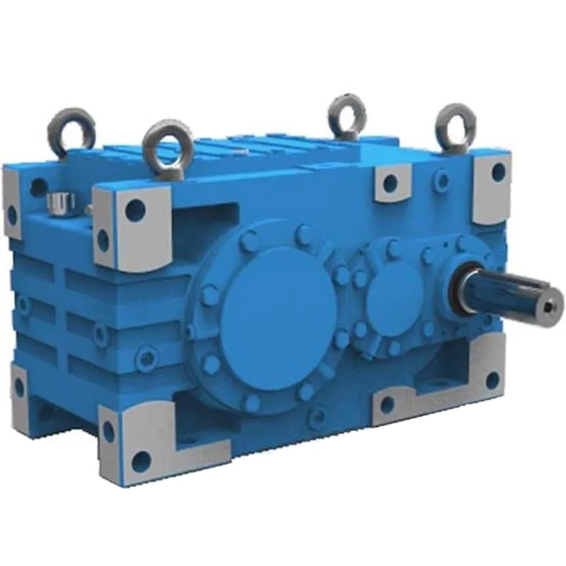
How do gear reducers contribute to energy efficiency in machinery and equipment?
Gear reducers play a significant role in enhancing energy efficiency in various machinery and equipment. Here's how they contribute:
1. Speed Reduction: Gear reducers are commonly used to reduce the speed of the input shaft, allowing the motor to operate at a higher speed where it's most efficient. This speed reduction helps match the motor's optimal operating range, reducing energy consumption.
2. Torque Increase: Gear reducers can increase torque output while decreasing speed, enabling machinery to handle higher loads without the need for a larger, more energy-intensive motor.
3. Matching Load Requirements: By adjusting gear ratios, gear reducers ensure that the machinery's output speed and torque match the load requirements. This prevents the motor from operating at unnecessary high speeds, saving energy.
4. Variable Speed Applications: In applications requiring variable speeds, gear reducers allow for efficient speed control without the need for continuous motor adjustments, improving energy usage.
5. Efficient Power Transmission: Gear reducers efficiently transmit power from the motor to the load, minimizing energy losses due to friction and inefficiencies.
6. Motor Downsizing: Gear reducers enable the use of smaller, more energy-efficient motors by converting their higher speed, lower torque output into the lower speed, higher torque needed for the application.
7. Decoupling Motor and Load Speeds: In cases where the motor and load speeds are inherently different, gear reducers ensure the motor operates at its most efficient speed while still delivering the required output to the load.
8. Overcoming Inertia: Gear reducers help overcome the inertia of heavy loads, making it easier for motors to start and stop, reducing energy consumption during frequent operation.
9. Precise Control: Gear reducers provide precise control over speed and torque, optimizing the energy consumption of machinery in processes that require accurate adjustments.
10. Regenerative Braking: In some applications, gear reducers can be used to capture and convert kinetic energy back into electrical energy during braking or deceleration, improving overall energy efficiency.
By efficiently managing speed, torque, and power transmission, gear reducers contribute to energy-efficient operation, reducing energy consumption, and minimizing the environmental impact of machinery and equipment.
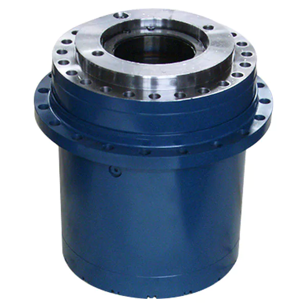
How do gear reducers ensure efficient power transmission and motion control?
Gear reducers play a vital role in ensuring efficient power transmission and precise motion control in various industrial applications. They achieve this through the following mechanisms:
- 1. Speed Reduction/Increase: Gear reducers allow you to adjust the speed between the input and output shafts. Speed reduction is essential when the output speed needs to be lower than the input speed, while speed increase is used when the opposite is required.
- 2. Torque Amplification: By altering the gear ratio, gear reducers can amplify torque from the input to the output shaft. This enables machinery to handle higher loads and provide the necessary force for various tasks.
- 3. Gear Train Efficiency: Well-designed gear trains within reducers minimize power losses during transmission. Helical and spur gears, for example, offer high efficiency by distributing load and reducing friction.
- 4. Precision Motion Control: Gear reducers provide precise control over rotational motion. This is crucial in applications where accurate positioning, synchronization, or timing is required, such as in robotics, CNC machines, and conveyor systems.
- 5. Backlash Reduction: Some gear reducers are designed to minimize backlash, which is the play between gear teeth. This reduction in play ensures smoother operation, improved accuracy, and better control.
- 6. Load Distribution: Gear reducers distribute the load evenly among multiple gear teeth, reducing wear and extending the lifespan of the components.
- 7. Shock Absorption: In applications where sudden starts, stops, or changes in direction occur, gear reducers help absorb and dampen shocks, protecting the machinery and ensuring reliable operation.
- 8. Compact Design: Gear reducers provide a compact solution for achieving specific speed and torque requirements, allowing for space-saving integration into machinery.
By combining these principles, gear reducers facilitate the efficient and controlled transfer of power, enabling machinery to perform tasks accurately, reliably, and with the required force, making them essential components in a wide range of industries.
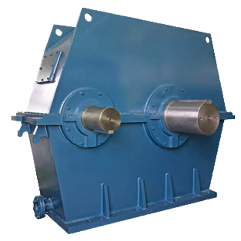
Function of Gear Reducers in Mechanical Systems
A gear reducer, also known as a gear reduction unit or gearbox, is a mechanical device designed to reduce the speed of an input shaft while increasing its torque output. It accomplishes this through the use of a set of interlocking gears with different sizes.
The primary function of a gear reducer in mechanical systems is to:
- Speed Reduction: The gear reducer takes the high-speed rotation of the input shaft and transmits it to the output shaft through a set of gears. The gears are configured in such a way that the output gear has a larger diameter than the input gear. As a result, the output shaft rotates at a lower speed than the input shaft, but with increased torque.
- Torque Increase: Due to the size difference between the input and output gears, the torque applied to the output shaft is greater than that of the input shaft. This torque multiplication allows the system to handle heavier loads and perform tasks requiring higher force.
Gear reducers are widely used in various industries and applications where it's necessary to adapt the speed and torque characteristics of a power source to meet the requirements of the driven equipment. They can be found in machinery such as conveyor systems, industrial machinery, vehicles, and more.


editor by CX 2024-03-08
China Professional CZPT S Series Helical Worm Hollow Shaft Gear Speed Reducer with Motor cvt gearbox
Product Description
S helical worm gearbox motor/ reducer motor
S series is 1 kind of Helical worm gearbox ,designed as Modularization and high-stainless cast iron case . It is combination of helical gear and worm gear ,which with higher efficiency and strength than simple aluminum worm gearbox . Due to their outstanding efficiency, these drives can be used in every industrial sector and tailored to individual torque and speed requirements. The gear ratios afforded by the helical-worm gear stage and the low noise levels during operation make these gear motor ideal low-cost solutions for simple applications
GPHQ S worm reducer motor materials
| housing material: | HT2OO high-strength cast iron |
| Gear material: | 20CrMnTi |
| Surface hardness of gear | HRC58°-62° |
| Gear core hardness | HRC33°-40° |
| Input/Output shaft material | 40Cr |
| Input/Output shaft hardness | HBS241°-286° |
| Shaft at oil seal position hardness | HRC48 ° -55 ° |
| Machining precision of gears material | Accurate grinding 6-5 grade |
| Efficiency | up to 98% |
| Noise(Max) | 60-68dB |
| Temp.rise: | 40°C |
| Vibration | ≤20um |
| Motor | IP54, F class ,B5 FLANGE |
| color : | blue (if you need big quantity ,we can done as your wanted color ) |
Our reduction geared motor Advantage
1,reasonable price with excellent quality
2,delivery in time
3,safe ,reliable ,economical and durable
4,stable transmission ,quiet operation
5,smooth running and low noise
6,nice appearance ,durable service life
7,high heat-radiating efficiency ,high carrying ability
8,each gearbox must be tested before packing
9.reply in high efficiency during 1 working day
10. professional to produce gearbox and electric motor .
If there is any question, please don't hesitate to contact with me (EVA), U can send us your inquiry. And you will get response in 1 working day.
GEARBOX CATALOGUE :
CERTIFICATION :
PRODUCING PROCESS:
PACKAGE :
for 1 container, directly loading ,for less, all goods with pallet.
FAQ
1, Q:what\'s your MOQ for ac gearbox motor ?
A: 1pc is ok for each type electric gear box motor
2, Q: What about your warranty for your induction speed reducer motor ?
A: 1 year ,but except man-made destroyed
3, Q: which payment way you can accept ?
A: TT, western union .
4, Q: how about your payment way ?
A: 100%payment in advanced less $5000 ,30% payment in advanced payment , 70% payment before sending over $5000.
5, Q: how about your packing of speed reduction motor ?
A: plywood case ,if size is small ,we will pack with pallet for less 1 container
6, Q: What information should be given, if I buy electric helical geared motor from you ?
A: rated power, ratio or output speed,type ,voltage , mounting way , quantity , if more is better .
/* March 10, 2571 17:59:20 */!function(){function s(e,r){var a,o={};try{e&&e.split(",").forEach(function(e,t){e&&(a=e.match(/(.*?):(.*)$/))&&1
| Application: | Motor, Machinery, Agricultural Machinery |
|---|---|
| Layout: | Bevel |
| Hardness: | Hardened Tooth Surface |
| Installation: | Horizontal Type |
| Step: | Double-Step |
| Motor Power: | 0.18kw-22kw |
| Customization: |
Available
| Customized Request |
|---|

How do gear reducers contribute to energy efficiency in machinery and equipment?
Gear reducers play a significant role in enhancing energy efficiency in various machinery and equipment. Here's how they contribute:
1. Speed Reduction: Gear reducers are commonly used to reduce the speed of the input shaft, allowing the motor to operate at a higher speed where it's most efficient. This speed reduction helps match the motor's optimal operating range, reducing energy consumption.
2. Torque Increase: Gear reducers can increase torque output while decreasing speed, enabling machinery to handle higher loads without the need for a larger, more energy-intensive motor.
3. Matching Load Requirements: By adjusting gear ratios, gear reducers ensure that the machinery's output speed and torque match the load requirements. This prevents the motor from operating at unnecessary high speeds, saving energy.
4. Variable Speed Applications: In applications requiring variable speeds, gear reducers allow for efficient speed control without the need for continuous motor adjustments, improving energy usage.
5. Efficient Power Transmission: Gear reducers efficiently transmit power from the motor to the load, minimizing energy losses due to friction and inefficiencies.
6. Motor Downsizing: Gear reducers enable the use of smaller, more energy-efficient motors by converting their higher speed, lower torque output into the lower speed, higher torque needed for the application.
7. Decoupling Motor and Load Speeds: In cases where the motor and load speeds are inherently different, gear reducers ensure the motor operates at its most efficient speed while still delivering the required output to the load.
8. Overcoming Inertia: Gear reducers help overcome the inertia of heavy loads, making it easier for motors to start and stop, reducing energy consumption during frequent operation.
9. Precise Control: Gear reducers provide precise control over speed and torque, optimizing the energy consumption of machinery in processes that require accurate adjustments.
10. Regenerative Braking: In some applications, gear reducers can be used to capture and convert kinetic energy back into electrical energy during braking or deceleration, improving overall energy efficiency.
By efficiently managing speed, torque, and power transmission, gear reducers contribute to energy-efficient operation, reducing energy consumption, and minimizing the environmental impact of machinery and equipment.

How do gear reducers ensure efficient power transmission and motion control?
Gear reducers play a vital role in ensuring efficient power transmission and precise motion control in various industrial applications. They achieve this through the following mechanisms:
- 1. Speed Reduction/Increase: Gear reducers allow you to adjust the speed between the input and output shafts. Speed reduction is essential when the output speed needs to be lower than the input speed, while speed increase is used when the opposite is required.
- 2. Torque Amplification: By altering the gear ratio, gear reducers can amplify torque from the input to the output shaft. This enables machinery to handle higher loads and provide the necessary force for various tasks.
- 3. Gear Train Efficiency: Well-designed gear trains within reducers minimize power losses during transmission. Helical and spur gears, for example, offer high efficiency by distributing load and reducing friction.
- 4. Precision Motion Control: Gear reducers provide precise control over rotational motion. This is crucial in applications where accurate positioning, synchronization, or timing is required, such as in robotics, CNC machines, and conveyor systems.
- 5. Backlash Reduction: Some gear reducers are designed to minimize backlash, which is the play between gear teeth. This reduction in play ensures smoother operation, improved accuracy, and better control.
- 6. Load Distribution: Gear reducers distribute the load evenly among multiple gear teeth, reducing wear and extending the lifespan of the components.
- 7. Shock Absorption: In applications where sudden starts, stops, or changes in direction occur, gear reducers help absorb and dampen shocks, protecting the machinery and ensuring reliable operation.
- 8. Compact Design: Gear reducers provide a compact solution for achieving specific speed and torque requirements, allowing for space-saving integration into machinery.
By combining these principles, gear reducers facilitate the efficient and controlled transfer of power, enabling machinery to perform tasks accurately, reliably, and with the required force, making them essential components in a wide range of industries.
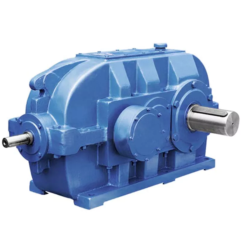
How do gear reducers handle variations in input and output speeds?
Gear reducers are designed to handle variations in input and output speeds through the use of different gear ratios and configurations. They achieve this by utilizing intermeshing gears of varying sizes to transmit torque and control rotational speed.
The basic principle involves connecting two or more gears with different numbers of teeth. When a larger gear (driving gear) engages with a smaller gear (driven gear), the rotational speed of the driven gear decreases while the torque increases. This reduction in speed and increase in torque enable gear reducers to efficiently adapt to variations in input and output speeds.
The gear ratio is a critical factor in determining how much the speed and torque change. It is calculated by dividing the number of teeth on the driven gear by the number of teeth on the driving gear. A higher gear ratio results in a greater reduction in speed and a proportionate increase in torque.
Planetary gear reducers, a common type, use a combination of gears including sun gears, planet gears, and ring gears to achieve different speed reductions and torque enhancements. This design provides versatility in handling variations in speed and torque requirements.
In summary, gear reducers handle variations in input and output speeds by using specific gear ratios and gear arrangements that enable them to efficiently transmit power and control motion characteristics according to the application's needs.


editor by CX 2024-02-07
China factory S Series Helical Worm Gearmotor Geared Motor Industrial Gearbox Flange-Mounted Hollow Shaft Speed Reducer cvt gearbox
Product Description
S series right-angle helical-worm reduction gearbox was designed after RV worm microreducer, which have a complete norm, wide speed for selection, and various mounting positions.
Products Description
S series is 1 kind of Helical worm gearbox, designed as Modularization and high-stainless cast iron case. It is combination of helical gear and worm gear, which with higher efficiency and strength than simple aluminum alloy worm gearbox. Due to their outstanding efficiency, these drives can be used in every industrial sector and tailored to individual torque and speed requirements. The gear ratios afforded by the helical-worm gear stage and the low noise levels during operation make these gearmotors ideal low-cost solutions for simple applications.
Perfect for the machinery and equipment of following industry:
• Conveyor & Material handling
• Mining & Quarry
• Crusher & Cement
• Automatic production line & Mixer
• Transport & Packaging
• Food machine & Beverage
• Construction & Metal processing
• Plastic & Chemical industry
| Housing material | High-strength cast iron HT250 |
| Gear material | 20CrMnTi |
| Input Power | 0.12-90KW |
| Output Torque | 3.5-4000N.m |
| Output Speed | 5-371 RPM |
| Gear Accuracy | 7 to 6 level |
| Gear Surface hardness | HRC58°-62° |
| Input/Output shaft hardness | HB220-250 |
| Noise(Max) | 60-70dB |
| Tem.rise(Max) | 40°C |
| Tem.rise(Oil Max) | 50°C |
| Vibration | ≤20um |
| Backlash | ≤20Arcmin |
| Effeciency | Single stage 98%, Double-stage:96%, Three-stage:94% |
| Mounting Position | Foot / Flange Mounting |
| Motor | IP55,F Class |
| Input power rating and permissible torque | |||||||
| Size | 37 | 47 | 57 | 67 | 77 | 87 | 97 |
| Structure | S SA SF SAF SAT SAZ | ||||||
| Rated Power | 0.12-1.5 | 0.12-1.5 | 0.18-3 | 0.25-5.5 | 0.55-7.5 | 0.75-15 | 1.5-22 |
| Ratio | 6.8-157.43 | 7.28-201 | 7.28-201 | 7.65-217.41 | 8.06-256.47 | 7.88-288 | 8.26-286.4 |
| Torque(N.m) | 90 | 170 | 300 | 520 | 1270 | 2280 | 4000 |
| Gear Unit Weight | |||||||
| Gear Unit Type | S37 | S47 | S57 | S67 | S77 | S87 | S97 |
| Weight |
7 | 10 | 14 | 26 | 50 | 100 | 170 |
| The weight are mean values, only for reference | |||||||
Company Profile
HangZhou CHINAMFG has been in power transmission products for 15 years. Our company is an industry transmission solutions manufacuturer and service provider.
The main products are worm reducers, helical worm reducers, helical bevel gear reducers, 90 degree gearbox, spiral bevel reducers, screw jack, standard industrial gearbox etc.
Our speed reducer and industrial gearbox are widely used in different factories, such as chemicals, energy, material handling, environmental, extraction, pulp and paper, steel and metal, food and beverage, and construction industries.
We have strong technical ability, manufacturing according to the ISO9002 quality control system guidelines.
Our industrial Gear, Gearbox, gearmotor and motor are sold to more than 30 countries. High quality, good price, in time response and sincere service are our value and promises. We aim at making happy cooperation with our customers, bring them reliable and comfortable service.
Application
FAQ
1. How to choose a gearbox which meets our requirement?
You can refer to our catalogue to choose the gearbox or we can help to choose when you provide
the technical information of required output torque, output speed and motor parameter etc.
2. What information shall we give before placing a purchase order?
a) Type of the gearbox, ratio, input and output type, input flange, mounting position, and motor informationetc.
b) Housing color.
c) Purchase quantity.
d) Other special requirements.
3. What industries are your gearboxes being used?
Our gearboxes are widely used in the areas of textile, food processing, beverage, chemical industry,
escalator,automatic storage equipment, metallurgy, tabacco, environmental protection, logistics and etc. /* March 10, 2571 17:59:20 */!function(){function s(e,r){var a,o={};try{e&&e.split(",").forEach(function(e,t){e&&(a=e.match(/(.*?):(.*)$/))&&1
| Application: | Motor, Marine, Toy, Car |
|---|---|
| Function: | Distribution Power, Clutch, Change Drive Torque, Change Drive Direction, Speed Changing, Speed Reduction, Speed Increase |
| Layout: | Coaxial |
| Hardness: | Hardened Tooth Surface |
| Installation: | as Request |
| Step: | Three-Step |
| Customization: |
Available
| Customized Request |
|---|
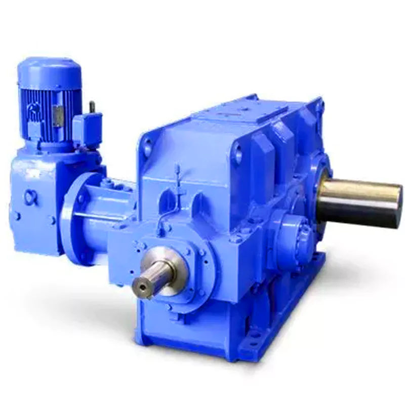
What are the considerations for choosing the appropriate lubrication for gear reducers?
Choosing the appropriate lubrication for gear reducers is crucial for ensuring optimal performance, longevity, and efficiency. Several considerations should be taken into account when selecting the right lubrication:
1. Load and Torque: The magnitude of the load and torque transmitted by the gear reducer affects the lubrication's viscosity and film strength requirements. Heavier loads may necessitate higher viscosity lubricants.
2. Operating Speed: The speed at which the gear reducer operates impacts the lubrication's ability to maintain a consistent and protective film between gear surfaces.
3. Temperature Range: Consider the temperature range of the operating environment. Lubricants with suitable viscosity indexes are crucial to maintaining performance under varying temperature conditions.
4. Contaminant Exposure: If the gear reducer is exposed to dust, dirt, water, or other contaminants, the lubrication should have proper sealing properties and resistance to contamination.
5. Lubrication Interval: Determine the desired maintenance interval. Some lubricants require more frequent replacement, while others offer extended operational periods.
6. Compatibility with Materials: Ensure that the chosen lubricant is compatible with the materials used in the gear reducer, including gears, bearings, and seals.
7. Noise and Vibration: Some lubricants have properties that can help reduce noise and dampen vibrations, improving the overall user experience.
8. Environmental Impact: Consider environmental regulations and sustainability goals when selecting lubricants.
9. Manufacturer Recommendations: Follow the manufacturer's recommendations and guidelines for lubrication type, viscosity grade, and maintenance intervals.
10. Monitoring and Analysis: Implement a lubrication monitoring and analysis program to assess lubricant condition and performance over time.
By carefully evaluating these considerations and consulting with lubrication experts, industries can choose the most suitable lubrication for their gear reducers, ensuring reliable and efficient operation.
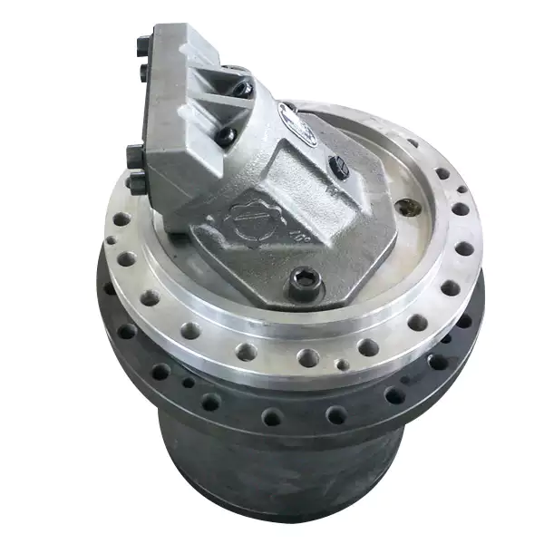
What factors should be considered when selecting the right gear reducer?
Choosing the appropriate gear reducer involves considering several crucial factors to ensure optimal performance and efficiency for your specific application:
- 1. Torque and Power Requirements: Determine the amount of torque and power your machinery needs for its operation.
- 2. Speed Ratio: Calculate the required speed reduction or increase to match the input and output speeds.
- 3. Gear Type: Select the appropriate gear type (helical, bevel, worm, planetary, etc.) based on your application's torque, precision, and efficiency requirements.
- 4. Mounting Options: Consider the available space and the mounting configuration that suits your machinery.
- 5. Environmental Conditions: Evaluate factors such as temperature, humidity, dust, and corrosive elements that may impact the gear reducer's performance.
- 6. Efficiency: Assess the gear reducer's efficiency to minimize power losses and improve overall system performance.
- 7. Backlash: Consider the acceptable level of backlash or play between gear teeth, which can affect precision.
- 8. Maintenance Requirements: Determine the maintenance intervals and procedures necessary for reliable operation.
- 9. Noise and Vibration: Evaluate noise and vibration levels to ensure they meet your machinery's requirements.
- 10. Cost: Compare the initial cost and long-term value of different gear reducer options.
By carefully assessing these factors and consulting with gear reducer manufacturers, engineers and industry professionals can make informed decisions to select the right gear reducer for their specific application, optimizing performance, longevity, and cost-effectiveness.

Function of Gear Reducers in Mechanical Systems
A gear reducer, also known as a gear reduction unit or gearbox, is a mechanical device designed to reduce the speed of an input shaft while increasing its torque output. It accomplishes this through the use of a set of interlocking gears with different sizes.
The primary function of a gear reducer in mechanical systems is to:
- Speed Reduction: The gear reducer takes the high-speed rotation of the input shaft and transmits it to the output shaft through a set of gears. The gears are configured in such a way that the output gear has a larger diameter than the input gear. As a result, the output shaft rotates at a lower speed than the input shaft, but with increased torque.
- Torque Increase: Due to the size difference between the input and output gears, the torque applied to the output shaft is greater than that of the input shaft. This torque multiplication allows the system to handle heavier loads and perform tasks requiring higher force.
Gear reducers are widely used in various industries and applications where it's necessary to adapt the speed and torque characteristics of a power source to meet the requirements of the driven equipment. They can be found in machinery such as conveyor systems, industrial machinery, vehicles, and more.


editor by CX 2024-01-31
China manufacturer Hollow Shaft Torque Arm Mounted Cast Iron Material Bvel Helical Gearbox with Servo Motor with Good quality
Product Description
Bevel helical gearbox with permanent magnet synchronous motor integrate variable frequency driver for conveyor
SNKG Series prorduct adopt harden teeth surface bevel gear and helical gear to drive, following the design principle of modularization , FEA analyse technology, unique low-noise gear tooth profile, with the characteristics of compact volume, high load performance and stable running, reliability and long service life.
Key Benefits
-Simple wiring, low cost
-Large amount of data, fast speed, 100m, data transmission is 500K
-All control units have the same condition, it means each node has the same rights to occupy the bus (send and receive)
-Communication rate meets control requirements, communication data amount supports required data reading.
-Electric eye and proximity switch sensor supply signal to the driver directly, it is convenient and reliable.
About Us
ZheJiang CHINAMFG Drive Co.,Ltd(Starshine) have a strong technical force with over 350 employees at present, including over 30 engineering technicians, 30 quality inspectors, covering an area of 80000 square CHINAMFG and kinds of advanced processing machines and testing equipments. We have a good foundation for the industry application development and service of high-end speed reducers & variators owning to the provincial engineering technology research center,the lab of gear speed reducers, and the base of modern R&D.
Our Team
Quality Control
Quality:Insist on Improvement,Strive for CHINAMFG With the development of equipment manufacturing indurstry,customer never satirsfy with the current quality of our products,on the contrary,wcreate the value of quality.
Quality policy:to enhance the overall level in the field of power transmission
Quality View:Continuous Improvement , pursuit of excellence
Quality Philosophy:Quality creates value
3. Incoming Quality Control
To establish the AQL acceptable level of incoming material control, to provide the material for the whole inspection, sampling, immunity. On the acceptance of qualified products to warehousing, substandard goods to take return, check, rework, rework inspection; responsible for tracking bad, to monitor the supplier to take corrective measures to prevent recurrence.
4. Process Quality Control
The manufacturing site of the first examination, inspection and final inspection, sampling according to the requirements of some projects, judging the quality change trend; found abnormal phenomenon of manufacturing, and supervise the production department to improve, eliminate the abnormal phenomenon or state.
5. FQC(Final QC)
After the manufacturing department will complete the product, stand in the customer's position on the finished product quality verification, in order to ensure the quality of customer expectations and needs.
6. OQC(Outgoing QC)
After the product sample inspection to determine the qualified, allowing storage, but when the finished product from the warehouse before the formal delivery of the goods, there is a check, this is called the shipment inspection.Check content:In the warehouse storage and transfer status to confirm, while confirming the delivery of the product is a product inspection to determine the qualified products.
Packing
Delivery
/* March 10, 2571 17:59:20 */!function(){function s(e,r){var a,o={};try{e&&e.split(",").forEach(function(e,t){e&&(a=e.match(/(.*?):(.*)$/))&&1
| Application: | Machinery, Agricultural Machinery |
|---|---|
| Function: | Distribution Power, Change Drive Torque, Change Drive Direction, Speed Changing, Speed Reduction |
| Layout: | Helical Bevel |
| Hardness: | Hardened Tooth Surface |
| Installation: | Torque Arm Type |
| Step: | Three-Step |
| Samples: |
US$ 290.28/Piece
1 Piece(Min.Order) | |
|---|
| Customization: |
Available
| Customized Request |
|---|
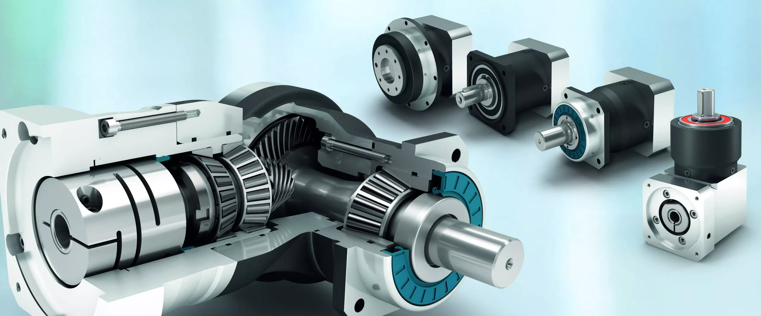
Handling Sudden Changes in Direction and Speed with Servo Gearboxes
Servo gearboxes are designed to handle sudden changes in direction and speed effectively, ensuring precise motion control even during dynamic operations. They employ several mechanisms to address these challenges:
1. Acceleration and Deceleration Profiles: Servo systems can be programmed with specific acceleration and deceleration profiles. This means that when a sudden change in speed or direction is commanded, the system can ramp up or down the speed smoothly, reducing the impact of sudden changes on the mechanical components.
2. Closed-Loop Control: Servo systems operate in a closed-loop configuration, where feedback sensors continuously monitor the actual position and speed of the system. When a sudden change is commanded, the controller can make real-time adjustments to ensure the system reaches the desired position accurately and smoothly.
3. Torque Control: Servo gearboxes are designed to provide high torque output even at low speeds. This is crucial for handling sudden changes in direction and speed, as the gearbox can deliver the required torque to quickly accelerate or decelerate the load.
4. Dynamic Response: Servo systems have fast dynamic response capabilities, which means they can quickly adapt to changes in input commands. This responsiveness allows the system to handle sudden changes in direction and speed without sacrificing accuracy or stability.
5. Electronic Damping: Some advanced servo systems incorporate electronic damping mechanisms that can be adjusted based on the application's requirements. This feature helps dampen vibrations and oscillations that may occur during sudden changes in motion.
6. Overcurrent and Overvoltage Protection: Servo systems are equipped with protection mechanisms that detect excessive currents or voltages. If a sudden change in direction or speed causes abnormal loads or voltages, the system can take corrective actions to prevent damage.
Overall, servo gearboxes excel in handling sudden changes in direction and speed by leveraging their closed-loop control, high torque output, and fast dynamic response capabilities. These features allow them to provide accurate and reliable motion control in dynamic and rapidly changing operating conditions.
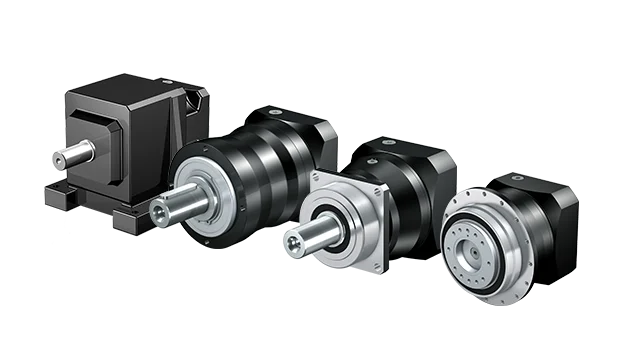
Contribution of Servo Gearboxes to Smooth Acceleration and Deceleration
Servo gearboxes play a crucial role in ensuring smooth acceleration and deceleration of machinery in motion control systems:
1. Precise Control: Servo gearboxes provide precise control over the rotational speed and torque of the output shaft. This control allows for gradual and controlled changes in speed, resulting in smooth acceleration and deceleration.
2. Feedback Mechanism: Servo systems typically incorporate feedback devices such as encoders or resolvers. These devices continuously monitor the actual position and speed of the output shaft and provide real-time feedback to the controller. This feedback enables the controller to adjust the input signals to the servo gearbox, ensuring accurate and smooth motion transitions.
3. Dynamic Response: Servo gearboxes are designed for high dynamic response, meaning they can quickly adjust their speed and torque based on the controller's commands. This responsiveness allows for rapid and smooth changes in speed and direction without sudden jerks or jolts.
4. Programmable Profiles: Many servo systems offer the capability to program acceleration and deceleration profiles. Engineers can define specific acceleration and deceleration curves tailored to the application's requirements. These profiles ensure that the machinery achieves the desired speed changes gradually and smoothly.
5. Reduced Wear and Tear: The controlled and gradual acceleration and deceleration provided by servo gearboxes reduce the wear and tear on mechanical components. Sudden changes in speed can lead to shock loads and vibration, potentially damaging the machinery. Servo gearboxes help mitigate these effects, extending the lifespan of components.
6. Increased Productivity: Smooth acceleration and deceleration reduce the chances of product damage, improve product quality, and enhance the overall efficiency of the process. This is particularly important in applications where precise motion control is critical.
Overall, servo gearboxes contribute to the seamless acceleration and deceleration of machinery by providing accurate control, dynamic responsiveness, and programmable motion profiles. These features ensure that machinery can achieve the desired speed changes while maintaining precision, efficiency, and longevity.
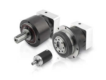
Contribution to High Accuracy and Repeatability
Servo gearboxes play a crucial role in achieving high accuracy and repeatability in motion control systems:
Precise Positioning: Servo gearboxes are designed to deliver precise angular displacement, allowing machines to accurately reach specific positions and orientations. This accuracy is vital in applications like robotic arms, CNC machines, and medical devices.
Low Backlash: Servo gearboxes are engineered to minimize backlash, which is the amount of play or lost motion between gear teeth. Low backlash ensures that any change in input direction is immediately translated into an accurate output movement, reducing errors and deviations.
High Torque Transmission: Servo gearboxes are capable of transmitting high torque with minimal energy loss. This enables precise control of rotational forces, ensuring that the output movement corresponds precisely to the input command.
Dynamic Response: Servo gearboxes exhibit rapid and accurate response to input signals. This responsiveness is crucial for applications requiring quick changes in motion, such as industrial robots, where rapid and precise movement is necessary for tasks like pick-and-place operations.
Feedback Systems: Servo systems often incorporate feedback devices like encoders and resolvers. These devices provide real-time information about the actual position, speed, and direction of the output shaft. The feedback data allows the servo controller to make continuous adjustments, resulting in accurate positioning and motion control.
Closed-Loop Control: Many servo systems operate in a closed-loop control configuration. In this setup, the controller continuously compares the desired position with the actual position using feedback data and makes corrections as needed. This closed-loop approach ensures that any errors or disturbances are quickly corrected, maintaining accuracy over time.
High-Resolution Encoders: Servo gearboxes often use high-resolution encoders that provide fine position feedback, enabling precise control of movements down to fractions of a degree. This level of resolution contributes to high accuracy in positioning.
Overall, servo gearboxes contribute to achieving high accuracy and repeatability by combining precision design, low backlash, responsive control, and feedback mechanisms. These characteristics make them essential components in applications where precise and repeatable motion is required.


editor by CX 2024-01-12
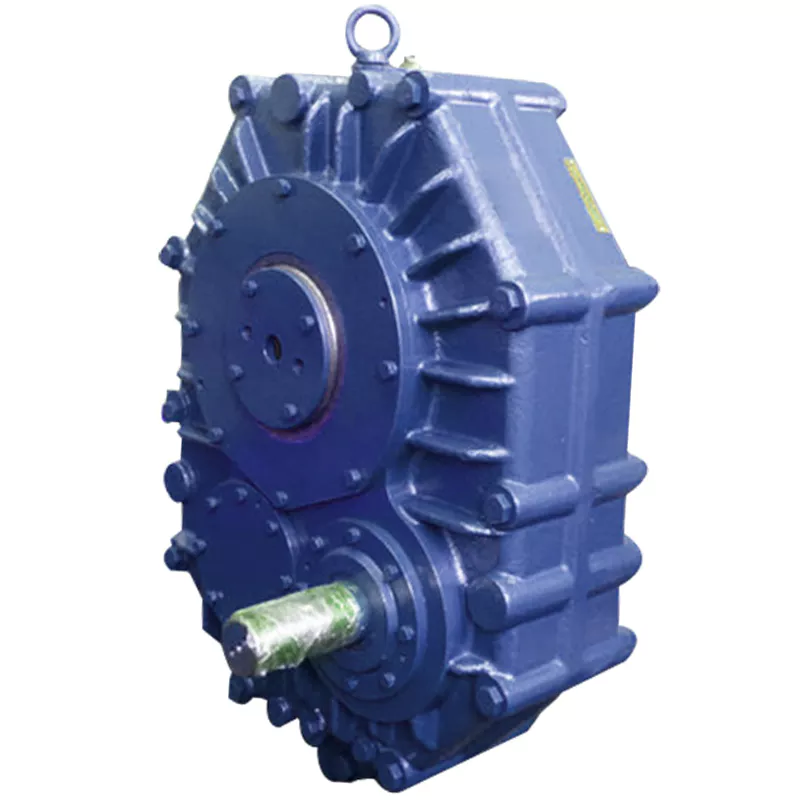
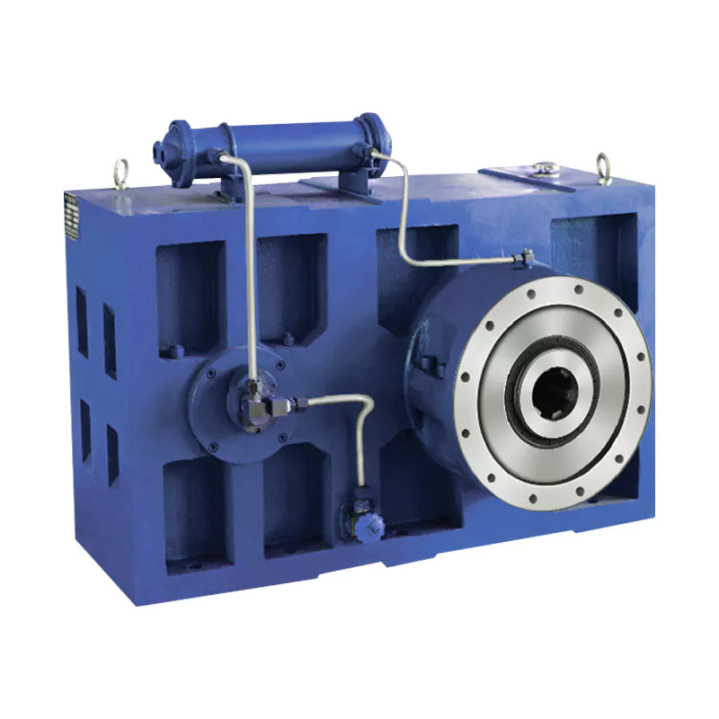
China Good quality Hollow Shaft CZPT Gearbox Zsyj450 Decelerator Single Screw Plastic Rubber Special Gear Reducer for Plastic Edge Band Extrusion Machine gearbox design
Product Description
Hollow Shaft CHINAMFG Gearbox Zsyj450 Decelerator Single Screw Plastic Rubber Special Gear Reducer for Plastic Edge Band Extrusion Machine
1, The gear is made of high-strength low-carbon alloy steel by carburizing and quenching. The hardness of
the tooth surface is up to HRC58-62. The gears are groun d grinding technology with high precision and
good contact.
2, High transmission efficiency: CHINAMFG is greater than 96.5%, double level is greater than 93%, third
level is greater than 90%.
3, Smooth operation and low noise.
4, Small size, light weight, long service life and high carrying capacity.
5, Easy to disassemble and easy to install.
|
No. |
gearbox model |
Ratio range |
recommend screw diameter/mm |
recommend power/HP |
rating load torque/N.m |
size(L*W*H)/mm |
Net weight/KG |
|
1 |
ZLYJ133 |
8/12.5/16/20 |
35/45/50 |
6~15 |
764 |
478*170*260 |
144 |
|
2 |
ZLYJ146 |
10/12.5/16/20 |
45/55 |
10~20 |
1165 |
560*250*320 |
205 |
|
3 |
ZLYJ173 |
10/16/20 |
55/65 |
15~30 |
1962 |
576*256*340 |
256 |
|
4 |
ZLYJ180 |
|
65 |
15~40 |
2764 |
650*256*400 |
350 |
|
5 |
ZLYJ200 |
12.5/16/20 |
65/75 |
30~60 |
3583 |
750*340*480 |
350 |
|
6 |
ZLYJ225 |
12.5/16/20 |
90 |
40~75 |
5334 |
800*360*500 |
650 |
|
7 |
ZLYJ250 |
16/12.5/20 |
100 |
50~100 |
6306 |
930*380*560 |
815 |
|
8 |
ZLYJ280 |
16/12.5/20 |
105/110 |
75~122 |
7643 |
970*410*600 |
1571 |
|
9 |
ZLYJ315 |
16/12.5/20 |
120 |
100~175 |
11822 |
1160*450*700 |
1410 |
|
10 |
ZLYJ330 |
16/12.5/20 |
150/160 |
150~217 |
21000 |
1160*450*700 |
1520 |
|
11 |
ZLYJ375 |
16/12.5/20 |
150/160 |
217~312 |
21096 |
1280*466*800 |
1800 |
|
12 |
ZLYJ420 |
16/12.5/20 |
150/165 |
272~428 |
25478 |
1420*550*920 |
1800 |
|
13 |
ZLYJ450 |
16/12.5/20 |
165 |
380~544 |
33885 |
1550*1200*1000 |
3560 |
| Application: | Motor, Electric Cars, Motorcycle, Machinery, Marine, Toy, Agricultural Machinery, Car |
|---|---|
| Hardness: | Hardened Tooth Surface |
| Installation: | 90 Degree |
| Layout: | Coaxial |
| Gear Shape: | Conical - Cylindrical Gear |
| Step: | Single-Step |
| Samples: |
US$ 9999/Piece
1 Piece(Min.Order) | |
|---|
Are there any disadvantages or limitations to using gear reducer systems?
While gear reducer systems offer numerous advantages, they also come with certain disadvantages and limitations that should be considered during the selection and implementation process:
1. Size and Weight: Gear reducers can be bulky and heavy, especially for applications requiring high gear ratios. This can impact the overall size and weight of the machinery or equipment, which may be a concern in space-constrained environments.
2. Efficiency Loss: Despite their high efficiency, gear reducers can experience energy losses due to friction between gear teeth and other components. This can lead to a reduction in overall system efficiency, particularly in cases where multiple gear stages are used.
3. Cost: The design, manufacturing, and assembly of gear reducers can involve complex processes and precision machining, which can contribute to higher initial costs compared to other power transmission solutions.
4. Maintenance: Gear reducer systems require regular maintenance, including lubrication, inspection, and potential gear replacement over time. Maintenance activities can lead to downtime and associated costs in industrial settings.
5. Noise and Vibration: Gear reducers can generate noise and vibrations, especially at high speeds or when operating under heavy loads. Additional measures may be needed to mitigate noise and vibration issues.
6. Limited Gear Ratios: While gear reducers offer a wide range of gear ratios, there may be limitations in achieving extremely high or low ratios in certain designs.
7. Temperature Sensitivity: Extreme temperatures can affect the performance of gear reducer systems, particularly if inadequate lubrication or cooling is provided.
8. Shock Loads: While gear reducers are designed to handle shock loads to some extent, severe shock loads or abrupt changes in torque can still lead to potential damage or premature wear.
Despite these limitations, gear reducer systems remain widely used and versatile components in various industries, and their disadvantages can often be mitigated through proper design, selection, and maintenance practices.
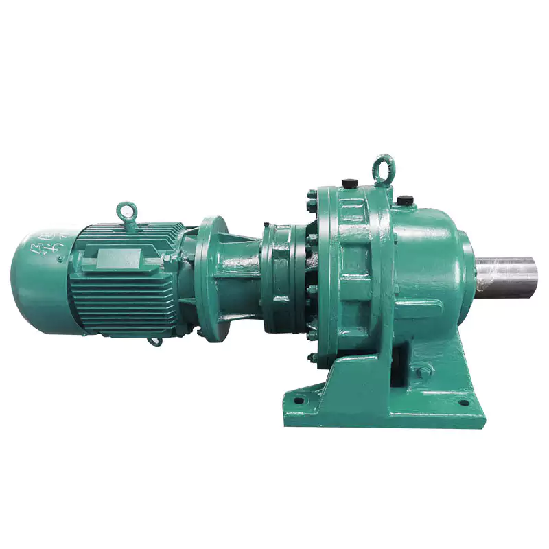
What role do gear ratios play in optimizing the performance of gear reducers?
Gear ratios play a crucial role in optimizing the performance of gear reducers by determining the relationship between input and output speeds and torques. A gear ratio is the ratio of the number of teeth between two meshing gears, and it directly influences the mechanical advantage and efficiency of the gear reducer.
1. Speed and Torque Conversion: Gear ratios allow gear reducers to convert rotational speed and torque according to the needs of a specific application. By selecting appropriate gear ratios, gear reducers can either reduce speed while increasing torque (speed reduction) or increase speed while decreasing torque (speed increase).
2. Mechanical Advantage: Gear reducers leverage gear ratios to provide mechanical advantage. In speed reduction configurations, a higher gear ratio results in a greater mechanical advantage, allowing the output shaft to deliver higher torque at a lower speed. This is beneficial for applications requiring increased force or torque, such as heavy machinery or conveyor systems.
3. Efficiency: Optimal gear ratios contribute to higher efficiency in gear reducers. By distributing the load across multiple gear teeth, gear reducers with suitable gear ratios minimize stress and wear on individual gear teeth, leading to improved overall efficiency and prolonged lifespan.
4. Speed Matching: Gear ratios enable gear reducers to match the rotational speeds of input and output shafts. This is crucial in applications where precise speed synchronization is required, such as in conveyors, robotics, and manufacturing processes.
When selecting gear ratios for a gear reducer, it's important to consider the specific requirements of the application, including desired speed, torque, efficiency, and mechanical advantage. Properly chosen gear ratios enhance the overall performance and reliability of gear reducers in a wide range of industrial and mechanical systems.
What industries and machinery commonly utilize gear reducers?
Gear reducers are widely used across various industries and types of machinery for torque reduction and speed control. Some common industries and applications include:
- 1. Manufacturing: Gear reducers are used in manufacturing equipment such as conveyors, mixers, and packaging machines to control speed and transmit power efficiently.
- 2. Automotive: They are utilized in vehicles for applications like power transmission in transmissions and differentials.
- 3. Aerospace: Gear reducers are used in aircraft systems, including landing gear mechanisms and engine accessories.
- 4. Robotics and Automation: They play a crucial role in robotic arms, CNC machines, and automated production lines.
- 5. Mining and Construction: Gear reducers are used in heavy machinery like excavators, bulldozers, and crushers for power transmission and torque multiplication.
- 6. Energy and Power Generation: Wind turbines, hydroelectric generators, and other power generation equipment use gear reducers to convert rotational speed and transmit power.
- 7. Marine and Shipbuilding: They are used in ship propulsion systems, steering mechanisms, and anchor handling equipment.
- 8. Material Handling: Gear reducers are essential in conveyor systems, elevators, and hoists for controlled movement of materials.
- 9. Food and Beverage: They find applications in food processing equipment like mixers, grinders, and packaging machines.
- 10. Paper and Pulp: Gear reducers are used in machinery for pulp processing, paper production, and printing.
These examples represent just a fraction of the industries and machinery that benefit from the use of gear reducers to optimize power transmission and achieve the desired motion characteristics.


editor by CX 2023-12-08
China supplier CZPT Nmrv Gearbox with Worm Gear Hollow Shaft Motor Reducer gearbox definition
Product Description
NMRV worm gearbox motor
NMRV series worm gear reducer:
Its structure,outline and installation dimensions as well as performance are same with that of
Europe an products,they are interchangeable,and the materials and machining process are advanced internationally.The product is featured by:
1.Low noise and temperature rise.
2.High bearing capability,smooth run and long service life.
3.ompact structure,samll volume,light weight,beautiful shape and easy to install.
4.Can run continuously under server environment,and has a good reliability.
GPHQ NMRV aluminum worm gearbox motor details:
| Type | GPHQ NMRV Worm Gear Speed Reducer /gearbox motor |
| Model: | NMRV25/30/ 40/ 50/ 63/ 75/ 90/110/130/150 |
| Input Power: | 0.06KW,0.09KW,0.12KW,0.18KW,0.22KW,0.25KW,0.37KW,0.55KW,0.75KW,1.1KW,1.5KW,2.2KW,4KW,5.5KW,7.5KW ,11KW,15KW |
| IEC Flange | 56B5,56B14,63B5,63B14,71B5,71B14,80B5,80B14,90B5,90B14,100B5, 100B14,112B5,112B14 132B5,160B5 |
| Ratio | 1: 7.5,10,15,20,25,30,40,50,60,80,100 |
| Material |
Housing: Die-Cast Aluminum Alloy for rv25-rv90 , die-cast cast iron for rv110 to rv150 |
| Worm Gear-brass+cast iron | |
| Worm-20CrMn Ti with carburizing and quenching, surface harness is 56-62HRC | |
| Shaft-chromium steel-45# | |
| Color: | Blue/Silver Or others if quantity is big |
| Packing: | Carton or plywood Case |
| Guarantee time : | 1 Year except except Man-made destruction |
| Usages: | Industrial Machine: Food Stuff, Ceramics,CHEMICAL,Packing,Dyeing,Woodworking,Glass. |
| shaft: | output CHINAMFG shaft or output hollow shaft |
FAQ
1, Q:what's your MOQ for ac gearbox motor ?
A: 1pc is ok for each type electric gear box motor
2, Q: What about your warranty for your induction speed reducer motor ?
A: 1 year ,but except man-made destroyed
3, Q: which payment way you can accept ?
A: TT, western union .
4, Q: how about your payment way ?
A: 100%payment in advanced less $5000 ,30% payment in advanced payment , 70% payment before sending over $5000.
5, Q: how about your packing of speed reduction motor ?
A: plywood case ,if size is small ,we will pack with pallet for less 1 container
6, Q: What information should be given, if I buy electric helical geared motor from you ?
A: rated power, ratio or output speed,type ,voltage , mounting way , quantity , if more is better.
| Application: | Motor, Machinery, Agricultural Machinery |
|---|---|
| Layout: | Right Angle |
| Hardness: | Hardened Tooth Surface |
| Step: | Single-Step |
| Ratio: | 7.5/10/15/20/25/30/40/50/60/80/100 |
| Gearbox Body: | Aluminum or Cast Iron |
| Customization: |
Available
| Customized Request |
|---|
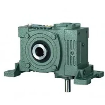
Can a Worm Gearbox Be Used in Heavy-Duty Machinery?
Yes, a worm gearbox can be used in heavy-duty machinery and is often chosen for such applications due to its inherent characteristics and advantages:
- High Torque Transmission: Worm gearboxes are known for their ability to transmit high torque loads, making them suitable for heavy-duty machinery that requires significant power transmission.
- Load Distribution: The design of worm gears provides robust load distribution and excellent contact between the worm and worm wheel teeth. This enhances their load-carrying capacity, making them capable of handling heavy loads without premature wear or failure.
- Compact Design: Worm gearboxes are compact and offer high reduction ratios in a single stage. This allows for the reduction of high input speeds to lower output speeds, often required in heavy-duty machinery.
- Overload Protection: Worm gears have a natural self-locking feature, which means the gear cannot be easily back-driven by external forces. This feature provides inherent overload protection, preventing damage to the gearbox and machinery in cases of sudden load spikes.
- Smooth Operation: Worm gearboxes offer smooth and steady operation, which is crucial for heavy-duty machinery where precision and controlled movement are essential.
However, when considering the use of a worm gearbox in heavy-duty applications, it's important to ensure proper engineering and sizing. The design should account for factors such as load, speed, duty cycle, lubrication, and temperature to ensure optimal performance and longevity.
Overall, worm gearboxes are well-suited for heavy-duty machinery across various industries, including mining, construction, manufacturing, and more.
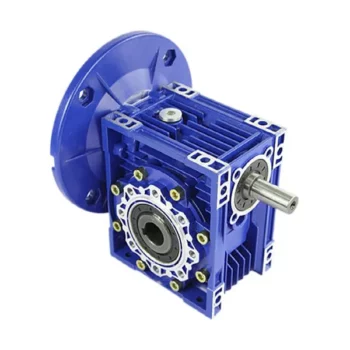
Energy Efficiency of a Worm Gearbox: What to Expect
The energy efficiency of a worm gearbox is an important factor to consider when evaluating its performance. Here's what you can expect in terms of energy efficiency:
- Typical Efficiency Range: Worm gearboxes are known for their compact size and high gear reduction capabilities, but they can exhibit lower energy efficiency compared to other types of gearboxes. The efficiency of a worm gearbox typically falls in the range of 50% to 90%, depending on various factors such as design, manufacturing quality, lubrication, and load conditions.
- Inherent Losses: Worm gearboxes inherently involve sliding contact between the worm and worm wheel. This sliding contact generates friction, leading to energy losses in the form of heat. The sliding action also contributes to lower efficiency when compared to gearboxes with rolling contact.
- Helical-Worm Design: Some manufacturers offer helical-worm gearbox designs that combine elements of helical and worm gearing. These designs aim to improve efficiency by incorporating helical gears in the reduction stage, which can lead to higher efficiency compared to traditional worm gearboxes.
- Lubrication: Proper lubrication plays a significant role in minimizing friction and improving energy efficiency. Using high-quality lubricants and ensuring the gearbox is adequately lubricated can help reduce losses due to friction.
- Application Considerations: While worm gearboxes might have lower energy efficiency compared to other types of gearboxes, they still offer advantages in terms of compactness, high torque transmission, and simplicity. Therefore, the decision to use a worm gearbox should consider the specific requirements of the application, including the trade-off between energy efficiency and other performance factors.
When selecting a worm gearbox, it's essential to consider the trade-offs between energy efficiency, torque transmission, gearbox size, and the specific needs of the application. Regular maintenance, proper lubrication, and selecting a well-designed gearbox can contribute to achieving the best possible energy efficiency within the limitations of worm gearbox technology.
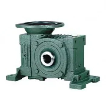
What Industries Commonly Use Worm Reducers?
Worm reducers are versatile mechanical components that find applications in various industries due to their unique advantages and capabilities. Some of the industries that commonly use worm reducers include:
- Material Handling: Worm reducers are widely used in material handling equipment such as conveyors, bucket elevators, and cranes to control movement and manage heavy loads.
- Automotive: They are utilized in automotive manufacturing processes, assembly lines, and vehicle positioning systems.
- Food and Beverage: Worm reducers are used in food processing and packaging machinery where hygiene and cleanliness are crucial.
- Agriculture: Agricultural equipment like irrigation systems and tractors use worm reducers for controlling rotational motion.
- Mining and Construction: Heavy-duty applications in mining equipment, excavators, and construction machinery benefit from the torque multiplication provided by worm reducers.
- Energy: Wind turbines and solar tracking systems use worm reducers to convert low-speed, high-torque motion into rotational energy.
- Textile: Textile machinery employs worm reducers for controlling speed and tension in weaving and spinning operations.
- Packaging: Packaging equipment relies on worm reducers for precise movement and positioning of packaging materials.
- Medical: Medical devices and equipment often utilize worm reducers for their accuracy and controlled motion.
- Printing: Printing machines use worm reducers to regulate paper feed and ensure consistent printing quality.
Worm reducers' ability to provide high torque output, compact design, and self-locking characteristics makes them suitable for applications requiring reliable and controlled motion across various industries.


editor by CX 2023-09-18
China Best Sales Nmrv 025 Hollow Shaft Worm Gearbox cycloidal gearbox
Product Description
Overview
-----------------------------------------------------------------------------------------------------------------------------------------------------------------------------------------------------------------------------------------------
Quick Details
Gearing Arrangement: Worm Brand Name: EED
Input Speed: 1400 rpm Output Speed: 14 rpm to 186 rpm
Rated Power: 0.06 ~ 4KW Output Torque: 2.6-479N.M
Color: Blue/Silver or on request Origin: ZHangZhoug, China (Mainland)
Warranty: 1 Year Application: Industry
-----------------------------------------------------------------------------------------------------------------------------------------------------------------------------------------------------------------------------------------------
Supply Ability
Supply Ability: 20000 Piece/Pieces per Month
Extra Service: OEM is welcome
QC System: ISO9001:2008
-----------------------------------------------------------------------------------------------------------------------------------------------------------------------------------------------------------------------------------------------
Packaging & Delivery
Package: Wooden box/Paper carton
Port: HangZhou/ZheJiang or on request
-----------------------------------------------------------------------------------------------------------------------------------------------------------------------------------------------------------------------------------------------
| TYPE | Worm Gear Speed Reducer/Worm Gearbox |
| MODEL | NMRV series size:571,030,040,050,063,075,090,110,130,150 |
| RATIO | 5,7.5,10,15,20,25,30,40,50,60,80,100 |
| COLOR | Blue(RAL5571)/Silver grey (RAL9571) or on your request |
| MATERIAL | Housing:Aluminum alloy |
| PACKING | Wooden box/Paper carton |
| BEARING | C&U |
| SEAL | SKF |
| WARRANTY | 1 Year |
| INPUT POWER | 0.09KM-15KM |
| USAGES | Foodstuffs, Ceramics, Packing, Chemicals, Pharmacy, Plastics, Paper-making, Machine-tools |
| IEC FLANGE | IEC standard flange or on request |
| LUBRICANT | Shell or Henry |
About CHINAMFG since 1984
HangZhou Melchizedek Import & Export Co., Ltd. is a leader manufactur in mechanism field and punching/stamp
ing field since 1984. Our main product, NMRV worm gear speed reducer and series helical gearbox, XDR,
XDF, XDK, XDShave reached the advanced technique index of the congeneric European and Janpanese produc
ts, We offer standard gears, sprockets, chains, pulleys, couplings, bushes and so on. We also can accept orders
of non-standard products, such as gears, shafts, punching parts ect, according to customers' Drawings or sam-
ples.
Our company has complete set of equipment including CNC, lathes, milling machines, gear hobbing machine, g-
ear grinding machine, gear honing machine, gear shaping machine, worm grinder, grinding machines, drilling m-
achines, boringmachines, planer, drawing benches, punches, hydraulic presses, plate shearing machines and s-
o on. We have advanced testing equipments also.
Our company has established favorable cooperation relationships with sub-suppliers involving casting, raw mat-
erial, heat treatment, surface finishing and so on.
| Application: | Motor, Machinery, Agricultural Machinery |
|---|---|
| Hardness: | Hardened Tooth Surface |
| Installation: | Horizontal Type |
| Gear Shape: | Worm |
| Step: | Single-Step |
| Type: | Worm Reducer |
| Customization: |
Available
| Customized Request |
|---|
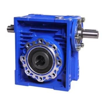
Can a Worm Gearbox be Used for High-Speed Applications?
Worm gearboxes are generally not recommended for high-speed applications due to their inherent design characteristics. Here's why:
- Efficiency: Worm gearboxes tend to have lower efficiency compared to other gearbox types, which means they can generate more heat and experience more energy loss at high speeds.
- Heat Generation: The sliding contact between the worm and worm wheel in a worm gearbox can lead to significant friction and heat generation, especially at high speeds. This heat can cause thermal expansion, affecting the gearbox's performance and longevity.
- Wear and Noise: High speeds can exacerbate wear and noise issues in worm gearboxes. Increased friction and wear can lead to faster degradation of components, resulting in reduced lifespan and increased maintenance needs.
- Backlash: Worm gearboxes may have higher backlash compared to other gearbox types, which can impact precision and accuracy in high-speed applications.
While worm gearboxes are more commonly used in applications requiring high torque and moderate speeds, they may not be the best choice for high-speed scenarios. If high-speed operation is a requirement, other gearbox types such as helical, spur, or planetary gearboxes are often better suited due to their higher efficiency, lower heat generation, and reduced wear at elevated speeds.
Worm Gearbox Applications in Robotics and Automation
Worm gearboxes play a crucial role in various robotics and automation applications due to their unique characteristics and benefits. Here are some common applications where worm gearboxes are used:
- Robotic Arm Movement: Worm gearboxes are employed in robotic arms to provide precise and controlled movement. The self-locking property of worm gearboxes helps maintain the arm's position without requiring additional brakes.
- Conveyor Systems: In automated production lines, worm gearboxes are used to drive conveyor belts and move materials or products along assembly lines with accuracy.
- Precision Positioning: Worm gearboxes are used in precision positioning systems, such as those found in pick-and-place robots and CNC machines. They ensure accurate and repeatable movements.
- Pan and Tilt Mechanisms: Worm gearboxes are utilized in pan and tilt mechanisms of surveillance cameras, robotic cameras, and sensors. The self-locking feature helps stabilize and maintain the desired angle.
- Automated Gates and Doors: Worm gearboxes are used in automated gate and door systems to control their opening and closing movements smoothly and safely.
- Material Handling: Robots in warehouses and distribution centers use worm gearboxes to manipulate and lift objects, enhancing efficiency in material handling.
- Medical Robotics: Worm gearboxes are employed in medical robots for surgical procedures, diagnostic equipment, and rehabilitation devices, ensuring precise and controlled movements.
- Industrial Robots: Industrial robots rely on worm gearboxes for various tasks, including welding, painting, assembly, and packaging, where precise movements are essential.
- Automated Testing Equipment: In testing and inspection applications, worm gearboxes provide the necessary movement and positioning for accurate testing and measurements.
- Food and Beverage Industry: Worm gearboxes are used in automated food processing and packaging systems, ensuring hygienic and precise movement of products.
Worm gearboxes are preferred in these applications due to their compact size, high torque output, self-locking feature, and ability to provide a right-angle drive. However, selecting the right gearbox requires considering factors such as load, speed, efficiency, and environmental conditions.
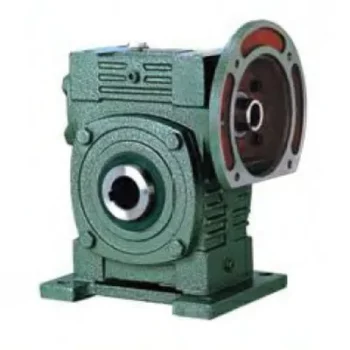
Types of Worm Gear Configurations and Their Uses
Worm gear configurations vary based on the arrangement of the worm and the gear it engages with. Here are common types and their applications:
- Single Enveloping Worm Gear: This configuration offers high torque transmission and efficiency. It's used in heavy-duty applications like mining equipment and industrial machinery.
- Double Enveloping Worm Gear: With increased contact area, this type provides higher load capacity and improved efficiency. It's used in aerospace applications, robotics, and precision machinery.
- Non-Throated Worm Gear: This type has a cylindrical worm without a throat. It's suitable for applications requiring precise motion control, such as CNC machines and robotics.
- Throated Worm Gear: Featuring a throat in the worm, this configuration offers smooth engagement and higher load capacity. It's used in conveyors, elevators, and automotive applications.
- Non-Modular Worm Gear: In this design, the worm and gear are a matched set, resulting in better meshing and efficiency. It's utilized in various industries where customization is essential.
- Modular Worm Gear: This type allows interchangeability of worm and gear components, providing flexibility in design and maintenance. It's commonly used in conveyors, mixers, and material handling systems.
Selecting the appropriate worm gear configuration depends on factors such as load capacity, efficiency, precision, and application requirements. Consulting gearbox experts can help determine the best configuration for your specific needs.


editor by CX 2023-09-15
China best Nmrv Series Hollow Shaft Worm Gear Reducer Horizontal Gearbox gearbox adjustment
Product Description
Product Parameters
Editing and broadcasting of main materials
1. Body, die-casting aluminum alloy;
2. Worm shaft, 20 Crq steel, high temperature treatment;
3. Worm gear, nickel bronze alloy;
4. Aluminum alloy body, sandblasting and surface anti-corrosion treatment;
5. Cast iron body, painted with bIu RA5571.
Regular center distance specification editing and broadcasting
Center distance: 130 (unit: mm).
Output hole/shaft diameter: 11, 14, 18, 25, 28, 35, 42, 45 (unit: mm)
Detailed Photos
|
NMRV-063-30-VS--AS-80B5-0.75KW-B3 |
|||
|
NMRV |
Means hole-input with flange |
||
|
NRV |
Means shaft-input without flange |
||
|
063 |
Centre-to-centre spacing of worm-gear speed reducer |
||
|
30 |
ratio |
||
|
VS |
Double input shaft |
F1(FA) |
Flange putput shaft |
|
AS |
Single output shaft |
AB |
Double output shaft |
|
PAM |
|
80B5 |
Motor mounting facility |
|
0.75KW |
|
B3 |
Mounting position |
|
N2 |
NRV571 |
NRV030 |
NRV040 |
NRV050 |
NRV063 |
NRV075 |
NRV090 |
NRV110 |
NRV130 |
|
400 |
390 |
530 |
1571 |
1400 |
1830 |
2160 |
2390 |
3571 |
3950 |
|
250 |
460 |
620 |
1200 |
1650 |
2150 |
2520 |
2800 |
3530 |
4610 |
|
150 |
550 |
740 |
1420 |
1960 |
2450 |
2990 |
3310 |
4180 |
5470 |
|
100 |
630 |
850 |
1620 |
2250 |
2910 |
3430 |
3800 |
4790 |
6260 |
|
60 |
740 |
1000 |
1920 |
2660 |
3450 |
4060 |
4500 |
5680 |
7420 |
|
40 |
850 |
1150 |
2200 |
3050 |
3950 |
4650 |
5150 |
6500 |
8500 |
|
25 |
990 |
1350 |
2570 |
3570 |
4620 |
5440 |
6571 |
7600 |
9940 |
|
10 |
1350 |
1830 |
3490 |
4840 |
6270 |
7380 |
8180 |
10320 |
13500 |
|
|
|
|
|
|
|
|
|
|
|
|
A |
50 |
65 |
84 |
101 |
120 |
131 |
162 |
191 |
203 |
|
B |
38 |
50 |
64 |
76 |
95 |
101 |
122 |
151 |
163 |
Use and safety guarantee
1. Please check and confirm the matching intensity between worm gear reducer and mechanical equipment before use to assure that it is in the safety range of worm gear reducer performance parameters
2. Worm gear reducer has filled with WA460 lubricating oil. Please replace the lubricating oil after the first starting of 400 hours and after then 4000 hours for lubricating oil replacing cycle
3. There should be enough lubrication in worm gear box and keep regular check with the oil level.
4. When installation. please be careful to avoid sharp instruments bruising the oil seals on output shaft to cause leakage
5. Please confirm the rotation direction before mechanical connection. If the rotation direction is not correct, it will possible injury or damage the devices
6. Please set safety covers in rotating position to avoid of injuring
7. Please pay full attention: it is very dangerous if there is off or falling when movin
| Hardness: | Hardened Tooth Surface |
|---|---|
| Installation: | 90 Degree |
| Layout: | Expansion |
| Gear Shape: | Bevel Gear |
| Step: | Single-Step |
| Type: | Gear Reducer |
| Samples: |
US$ 30/Piece
1 Piece(Min.Order) | |
|---|

Can a Worm Gearbox Be Used in Heavy-Duty Machinery?
Yes, a worm gearbox can be used in heavy-duty machinery and is often chosen for such applications due to its inherent characteristics and advantages:
- High Torque Transmission: Worm gearboxes are known for their ability to transmit high torque loads, making them suitable for heavy-duty machinery that requires significant power transmission.
- Load Distribution: The design of worm gears provides robust load distribution and excellent contact between the worm and worm wheel teeth. This enhances their load-carrying capacity, making them capable of handling heavy loads without premature wear or failure.
- Compact Design: Worm gearboxes are compact and offer high reduction ratios in a single stage. This allows for the reduction of high input speeds to lower output speeds, often required in heavy-duty machinery.
- Overload Protection: Worm gears have a natural self-locking feature, which means the gear cannot be easily back-driven by external forces. This feature provides inherent overload protection, preventing damage to the gearbox and machinery in cases of sudden load spikes.
- Smooth Operation: Worm gearboxes offer smooth and steady operation, which is crucial for heavy-duty machinery where precision and controlled movement are essential.
However, when considering the use of a worm gearbox in heavy-duty applications, it's important to ensure proper engineering and sizing. The design should account for factors such as load, speed, duty cycle, lubrication, and temperature to ensure optimal performance and longevity.
Overall, worm gearboxes are well-suited for heavy-duty machinery across various industries, including mining, construction, manufacturing, and more.

Materials Used for Worm Gears
Worm gears are manufactured using a variety of materials to meet different application requirements. Some commonly used materials for worm gears include:
- Steel: Steel is a popular choice for worm gears due to its strength, durability, and wear resistance. It can handle heavy loads and is often used in industrial applications.
- Bronze: Bronze offers good lubricity and is commonly used for the worm gear (worm) component. It provides effective wear resistance and works well in applications where quiet operation is essential.
- Cast Iron: Cast iron is known for its high strength and durability. It's often used for worm gears in applications where shock loads or heavy-duty conditions are expected.
- Aluminum: Aluminum worm gears are lightweight and corrosion-resistant, making them suitable for applications where weight reduction is important.
- Plastic: Some worm gears are made from plastic materials such as nylon or acetal. These materials are often chosen for their self-lubricating properties and quiet operation.
- Composite Materials: Composite materials can offer a combination of properties, such as lightweight construction and corrosion resistance. They can be suitable for specific applications.
The choice of material depends on factors such as the application's load, speed, operating environment, and required performance characteristics. It's important to consider these factors when selecting the appropriate material for worm gears to ensure optimal performance and longevity.
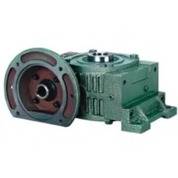
Can a Worm Gearbox Provide High Torque Output?
Yes, a worm gearbox is capable of providing high torque output due to its unique design and principle of operation. Worm gears are known for their high torque multiplication capabilities, making them suitable for applications that require significant torque transfer.
The torque output of a worm gearbox is influenced by several factors:
- Lead Angle: The lead angle of the worm affects the mechanical advantage of the gear system. A larger lead angle can result in higher torque output.
- Worm Diameter: A larger diameter worm can offer increased torque output as it provides more contact area with the gear.
- Gear Ratio: The gear ratio between the worm and the gear determines the torque multiplication factor. A higher gear ratio leads to higher torque output.
- Lubrication: Proper lubrication is essential to minimize friction and ensure efficient torque transmission.
- Material and Quality: High-quality materials and precision manufacturing contribute to the gearbox's ability to handle high torque loads.
Due to their ability to provide high torque output in a compact form factor, worm gearboxes are commonly used in various industrial applications, including heavy machinery, construction equipment, conveyor systems, and more.


editor by CX 2023-09-15
China Professional Tractor Pto Driveshaft Driveline Factory Hollow Spline Cardan Adapter Universal Joint Yoke Flexible Front Prop Rear CV Axle Propeller Automobile Drive Shaft
Product Description
Tractor Pto Driveshaft Driveline Factory Hollow Spline Cardan Adapter Universal Joint Yoke Flexible Front Prop Rear CV Axle Propeller Automobile Drive Shaft
Product Description
Agricultural truck universal joint steering
PTO Shaft
| Function of PTO Shaft | Drive Shaft Parts & Power Transmission |
| Usage of PTO Shaft | Kinds of Tractors & Farm Implements |
| Yoke Types for PTO Shaft | Double push pin, Bolt pins, Split pins, Pushpin, Quick release, Ball attachment, Collar….. |
| Processing Of Yoke | Forging |
| PTO Shaft Plastic Cover | YW; BW; YS; BS; Etc |
| Colors of PTO Shaft | Green; Orange; Yellow; Black Ect. |
| PTO Shaft Series | T1-T10; L1-L6;S6-S10;10HP-150HP with SA,RA,SB,SFF,WA,CV Etc |
| Tube Types for PTO Shaft | Lemon, Triangular, Star, Square, Hexangular, Spline, Special Ect |
| Processing Of Tube | Cold drawn |
| Spline Types for PTO Shaft | 1 1/8″ Z6;1 3/8″ Z6; 1 3/8″ Z21 ;1 3/4″ Z20; 1 3/4″ Z6; 8-38*32*6 8-42*36*7; 8-48*42*8; |
We also sell accessories for the pto shaft, including :
Yoke: CV socket yoke, CV weld yoke, flange yoke, end yoke, weld yoke, slip yoke
CV center housing, tube, spline, CV socket flange, u-joint, dust cap
Light vehicle drive line
Our products can be used for transmission shafts of the following brands
Toyota, Mitsubishi, Nissan, Isu zu, Suzuki, Dafa, Honda, Hyundai, Mazda, Fiat, Re nault, Kia, Dacia, Ford. Dodge, Land Rover, Peu geot, Volkswagen Audi, BMW Benz Volvo, Russian models
Gear shaft
Company Profile
Related Products
Application:
Company information:
| Material: | Carbon Steel |
|---|---|
| Load: | Drive Shaft |
| Stiffness & Flexibility: | Stiffness / Rigid Axle |
| Journal Diameter Dimensional Accuracy: | IT6-IT9 |
| Axis Shape: | Straight Shaft |
| Shaft Shape: | Real Axis |
| Samples: |
US$ 38/Piece
1 Piece(Min.Order) | |
|---|

What maintenance practices are essential for prolonging the lifespan of PTO shafts?
Maintaining proper care and performing regular maintenance on Power Take-Off (PTO) shafts is crucial for prolonging their lifespan and ensuring optimal performance. By following essential maintenance practices, you can prevent premature wear, identify potential issues early on, and maximize the longevity of your PTO shafts. Here are some key maintenance practices to consider:
1. Regular Inspection: Perform routine visual inspections of the PTO shaft to check for any signs of damage, wear, or misalignment. Look for cracks, dents, bent sections, or loose components. Inspect the universal joints, coupling mechanisms, protective guards, and other associated parts. Pay attention to any unusual noises, vibrations, or changes in performance, as these can indicate underlying issues that require attention.
2. Lubrication: Proper lubrication is essential for the smooth operation and longevity of PTO shafts. Follow the manufacturer's recommendations regarding lubrication intervals and use the recommended lubricant type. Apply lubrication to the universal joints, CV joints (if applicable), and other moving parts as specified. Regularly check for adequate lubricant levels and replenish if necessary. Ensure that the lubricant used is compatible with the shaft material and does not attract dirt or debris that could cause abrasion or damage.
3. Cleaning: Keep the PTO shaft clean and free from dirt, debris, and other contaminants. Regularly remove any accumulated dirt, grease, or residue using a brush or compressed air. Be particularly diligent in cleaning the universal joints and areas where the shaft connects to other components. Cleaning prevents the buildup of abrasive particles that can accelerate wear and compromise the shaft's performance.
4. Guard Inspection and Maintenance: Check the protective guards and shields regularly to ensure they are securely in place and free from damage. Guards play a critical role in preventing accidental contact with the rotating shaft and minimizing the risk of injury. Repair or replace any damaged or missing guards promptly. Ensure that the guards are correctly aligned and provide sufficient coverage for all moving parts of the PTO shaft.
5. Torque and Fastener Checks: Periodically inspect and check the torque of fasteners, such as bolts and nuts, that secure the PTO shaft and associated components. Over time, vibration and normal operation can loosen these fasteners, compromising the integrity of the shaft. Use the appropriate torque specifications provided by the manufacturer to ensure proper tightening. Regularly verify the tightness of fasteners and retighten as necessary.
6. Shear Bolt or Slip Clutch Maintenance: If your PTO shaft incorporates shear bolt or slip clutch mechanisms, ensure they are functioning correctly. Inspect the shear bolts for signs of wear or damage, and replace them when necessary. Check the slip clutch for proper adjustment and smooth operation. Follow the manufacturer's recommendations regarding maintenance and adjustment of these safety mechanisms to ensure their effectiveness in protecting the driveline components.
7. Proper Storage: When the PTO shaft is not in use, store it in a clean and dry environment. Protect the shaft from exposure to moisture, extreme temperatures, and corrosive substances. If possible, store the shaft in a vertical position to prevent bending or distortion. Consider using protective covers or cases to shield the shaft from dust, dirt, and other potential sources of damage.
8. Operator Training: Provide proper training to operators on the correct operation, maintenance, and safety procedures related to the PTO shafts. Educate them about the importance of regular inspections, lubrication, and adherence to recommended maintenance practices. Encourage operators to report any abnormalities or concerns promptly to prevent further damage and ensure timely repairs or adjustments.
9. Manufacturer and Expert Guidance: Consult the manufacturer's guidelines and recommendations regarding maintenance practices specific to your PTO shaft model. Additionally, seek advice from experts or authorized service technicians who are knowledgeable about PTO shaft maintenance. They can provide valuable insights and assistance in implementing the best maintenance practices for your specific PTO shafts.
By following these maintenance practices, you can extend the lifespan of your PTO shafts, optimize their performance, and reduce the likelihood of unexpected failures or costly repairs. Regular inspections, lubrication, cleaning, guard maintenance, torque checks, and proper storage are all essential in ensuring the longevity and reliability of your PTO shafts.

Can you provide real-world examples of equipment that use PTO shafts?
Power Take-Off (PTO) shafts are extensively used in various industries, particularly in agriculture and construction. They provide a reliable power source for a wide range of equipment, enabling efficient operation and increased productivity. Here are some real-world examples of equipment that commonly use PTO shafts:
1. Agricultural Machinery:
- Tractor Implements: A wide array of tractor-mounted implements rely on PTO shafts for power transfer. These include:
- Mowers and rotary cutters
- Balers and hay equipment
- Tillers and cultivators
- Seeders and planters
- Sprayers
- Manure spreaders
- Harvesters, such as combine harvesters and forage harvesters
- Stationary Equipment: PTO shafts are also used in stationary agricultural equipment, including:
- Feed grinders and mixers
- Silo unloaders
- Grain augers and elevators
- Irrigation pumps
- Wood chippers and shredders
- Stump grinders
2. Construction and Earthmoving Equipment:
- Backhoes and Excavators: PTO shafts can be found in backhoes and excavators, powering attachments such as augers, hydraulic hammers, and brush cutters.
- Post Hole Diggers: Post hole diggers used for fence installation often rely on PTO shafts to transfer power to the digging mechanism.
- Trenchers: Trenching machines equipped with PTO shafts efficiently dig trenches for utility installations, drainage systems, or irrigation lines.
- Stump Grinders: Stump grinders used in land clearing and tree removal operations often utilize PTO shafts to power their cutting blades.
- Soil Stabilizers and Road Reclaimers: These machines use PTO shafts to drive the rotor and milling drums, which pulverize and mix materials for road construction and maintenance.
3. Forestry Equipment:
- Wood Chippers: Wood chippers used for processing tree branches and logs into wood chips are commonly powered by PTO shafts.
- Brush Cutters and Mulchers: PTO-driven brush cutters and mulchers are employed to clear vegetation and maintain forested areas.
- Log Splitters: Log splitters that split logs into firewood often utilize PTO shafts to power the splitting mechanism.
4. Utility Equipment:
- Generators: Some generators are designed to be driven by PTO shafts, providing an auxiliary power source for various applications in remote locations or during power outages.
- Pumps: PTO-driven pumps are commonly used for agricultural irrigation, water transfer, and dewatering applications.
5. Specialty Equipment:
- Ice Resurfacers: PTO shafts are employed in ice resurfacing machines used in ice rinks to maintain a smooth ice surface for ice hockey and figure skating.
- Air Compressors: Some air compressors are driven by PTO shafts, providing a source of compressed air for various applications.
These examples represent a range of equipment that extensively relies on PTO shafts for power transfer. PTO shafts enable the efficient operation of these machines, increasing productivity and versatility across various industries.

How do PTO shafts contribute to transferring power from tractors to implements?
PTO shafts (Power Take-Off shafts) play a critical role in transferring power from tractors to implements in agricultural and industrial settings. They provide a reliable and efficient means of power transmission, enabling tractors to drive various implements and perform a wide range of tasks. Here's a detailed explanation of how PTO shafts contribute to transferring power from tractors to implements:
Power Source: Tractors are equipped with powerful engines designed to generate substantial amounts of mechanical power. This power is harnessed to drive the tractor's wheels and operate hydraulic systems, as well as to provide power for the attachment of implements through the PTO shaft. The PTO shaft typically connects to the rear or side of the tractor, where the power take-off mechanism is located. The power take-off derives power directly from the tractor's engine or transmission, allowing for efficient power transfer to the PTO shaft.
PTO Shaft Design: PTO shafts are designed as driveline components that transmit rotational power and torque from the tractor's power take-off to the implement. They consist of a hollow metal tube with universal joints at each end. The universal joints accommodate angular misalignments and allow the PTO shaft to transmit power even when the tractor and implement are not perfectly aligned. The PTO shaft is also equipped with a safety shield or guard to prevent accidental contact with the rotating shaft, ensuring operator safety during operation.
PTO Engagement: To transfer power from the tractor to the implement, the PTO shaft needs to be engaged. Tractors are equipped with a PTO clutch mechanism that allows operators to engage or disengage the PTO shaft as needed. When the PTO clutch is engaged, power flows from the tractor's engine through the power take-off mechanism and into the PTO shaft. This rotational power is then transmitted through the PTO shaft to the implement, driving its working components.
Rotational Power Transmission: The rotational power generated by the tractor's engine is transferred to the PTO shaft through the power take-off mechanism. The PTO shaft, being directly connected to the power take-off, rotates at the same speed as the engine. This rotational power is then transmitted from the PTO shaft to the implement's driveline or gearbox. The implement's driveline, in turn, distributes the power to the implement's working components, such as blades, augers, or pumps, enabling them to carry out their respective functions.
Matching Speed and Power: PTO shafts are designed to match the rotational speed and power requirements of various implements. Tractors often feature multiple speed settings for the PTO, allowing operators to select the appropriate speed for the specific implement being used. Different implements may require different rotational speeds to operate optimally, and the PTO shaft allows for easy adjustment to match those requirements. Additionally, the power generated by the tractor's engine is transmitted through the PTO shaft, providing the necessary torque to drive the implement's working components effectively.
Versatility and Efficiency: PTO shafts offer significant versatility and efficiency in agricultural and industrial operations. They allow tractors to power a wide range of implements, including mowers, balers, tillers, sprayers, and grain augers, among others. By connecting implements directly to the tractor's power source, operators can quickly switch between tasks without the need for separate power generators or engines. This versatility and efficiency streamline workflow, reduce costs, and increase overall productivity in agricultural and industrial settings.
Safety Considerations: While PTO shafts are essential for power transmission, they can pose safety risks if mishandled. The rotating shaft and universal joints can cause severe injuries if operators come into contact with them while in operation. That's why PTO shafts are equipped with safety shields or guards to prevent accidental contact. Operators should always ensure that the safety shields are in place and secure before engaging the PTO shaft. Proper training, adherence to safety guidelines, and regular maintenance of PTO shafts and associated safety features are crucial to ensuring safe operation.
In summary, PTO shafts are vital components that enable the transfer of power from tractors to implements in agricultural and industrial applications. They provide a reliable and efficient means of power transmission, allowing tractors to drive various implements and perform a wide range of tasks. By engaging the PTO clutch and transmitting rotational power through the PTO shaft, tractors power the working components of implements, providing versatility, efficiency, and productivity in agricultural and industrial operations.


editor by CX 2023-09-15
China Hot selling Tractor Pto Driveshaft Driveline Factory Hollow Spline Cardan Adapter Universal Joint Yoke Flexible Front Prop Rear CV Axle Propeller Automobile Drive Shaft
Product Description
Tractor Pto Driveshaft Driveline Factory Hollow Spline Cardan Adapter Universal Joint Yoke Flexible Front Prop Rear CV Axle Propeller Automobile Drive Shaft
Product Description
Agricultural truck universal joint steering
PTO Shaft
| Function of PTO Shaft | Drive Shaft Parts & Power Transmission |
| Usage of PTO Shaft | Kinds of Tractors & Farm Implements |
| Yoke Types for PTO Shaft | Double push pin, Bolt pins, Split pins, Pushpin, Quick release, Ball attachment, Collar….. |
| Processing Of Yoke | Forging |
| PTO Shaft Plastic Cover | YW; BW; YS; BS; Etc |
| Colors of PTO Shaft | Green; Orange; Yellow; Black Ect. |
| PTO Shaft Series | T1-T10; L1-L6;S6-S10;10HP-150HP with SA,RA,SB,SFF,WA,CV Etc |
| Tube Types for PTO Shaft | Lemon, Triangular, Star, Square, Hexangular, Spline, Special Ect |
| Processing Of Tube | Cold drawn |
| Spline Types for PTO Shaft | 1 1/8″ Z6;1 3/8″ Z6; 1 3/8″ Z21 ;1 3/4″ Z20; 1 3/4″ Z6; 8-38*32*6 8-42*36*7; 8-48*42*8; |
We also sell accessories for the pto shaft, including :
Yoke: CV socket yoke, CV weld yoke, flange yoke, end yoke, weld yoke, slip yoke
CV center housing, tube, spline, CV socket flange, u-joint, dust cap
Light vehicle drive line
Our products can be used for transmission shafts of the following brands
Toyota, Mitsubishi, Nissan, Isu zu, Suzuki, Dafa, Honda, Hyundai, Mazda, Fiat, Re nault, Kia, Dacia, Ford. Dodge, Land Rover, Peu geot, Volkswagen Audi, BMW Benz Volvo, Russian models
Gear shaft
Company Profile
Related Products
Application:
Company information:
| Material: | Carbon Steel |
|---|---|
| Load: | Drive Shaft |
| Stiffness & Flexibility: | Stiffness / Rigid Axle |
| Journal Diameter Dimensional Accuracy: | IT6-IT9 |
| Axis Shape: | Straight Shaft |
| Shaft Shape: | Real Axis |
| Samples: |
US$ 38/Piece
1 Piece(Min.Order) | |
|---|

How do drive shafts handle variations in speed and torque during operation?
Drive shafts are designed to handle variations in speed and torque during operation by employing specific mechanisms and configurations. These mechanisms allow the drive shafts to accommodate the changing demands of power transmission while maintaining smooth and efficient operation. Here's a detailed explanation of how drive shafts handle variations in speed and torque:
1. Flexible Couplings:
Drive shafts often incorporate flexible couplings, such as universal joints (U-joints) or constant velocity (CV) joints, to handle variations in speed and torque. These couplings provide flexibility and allow the drive shaft to transmit power even when the driving and driven components are not perfectly aligned. U-joints consist of two yokes connected by a cross-shaped bearing, allowing for angular movement between the drive shaft sections. This flexibility accommodates variations in speed and torque and compensates for misalignment. CV joints, which are commonly used in automotive drive shafts, maintain a constant velocity of rotation while accommodating changing operating angles. These flexible couplings enable smooth power transmission and reduce vibrations and wear caused by speed and torque variations.
2. Slip Joints:
In some drive shaft designs, slip joints are incorporated to handle variations in length and accommodate changes in distance between the driving and driven components. A slip joint consists of an inner and outer tubular section with splines or a telescoping mechanism. As the drive shaft experiences changes in length due to suspension movement or other factors, the slip joint allows the shaft to extend or compress without affecting the power transmission. By allowing axial movement, slip joints help prevent binding or excessive stress on the drive shaft during variations in speed and torque, ensuring smooth operation.
3. Balancing:
Drive shafts undergo balancing procedures to optimize their performance and minimize vibrations caused by speed and torque variations. Imbalances in the drive shaft can lead to vibrations, which not only affect the comfort of vehicle occupants but also increase wear and tear on the shaft and its associated components. Balancing involves redistributing mass along the drive shaft to achieve even weight distribution, reducing vibrations and improving overall performance. Dynamic balancing, which typically involves adding or removing small weights, ensures that the drive shaft operates smoothly even under varying speeds and torque loads.
4. Material Selection and Design:
The selection of materials and the design of drive shafts play a crucial role in handling variations in speed and torque. Drive shafts are typically made from high-strength materials, such as steel or aluminum alloys, chosen for their ability to withstand the forces and stresses associated with varying operating conditions. The diameter and wall thickness of the drive shaft are also carefully determined to ensure sufficient strength and stiffness. Additionally, the design incorporates considerations for factors such as critical speed, torsional rigidity, and resonance avoidance, which help maintain stability and performance during speed and torque variations.
5. Lubrication:
Proper lubrication is essential for drive shafts to handle variations in speed and torque. Lubricating the joints, such as U-joints or CV joints, reduces friction and heat generated during operation, ensuring smooth movement and minimizing wear. Adequate lubrication also helps prevent the binding of components, allowing the drive shaft to accommodate speed and torque variations more effectively. Regular lubrication maintenance is necessary to ensure optimal performance and extend the lifespan of the drive shaft.
6. System Monitoring:
Monitoring the performance of the drive shaft system is important to identify any issues related to variations in speed and torque. Unusual vibrations, noises, or changes in power transmission can indicate potential problems with the drive shaft. Regular inspections and maintenance checks allow for the early detection and resolution of issues, helping to prevent further damage and ensure the drive shaft continues to handle speed and torque variations effectively.
In summary, drive shafts handle variations in speed and torque during operation through the use of flexible couplings, slip joints, balancing procedures, appropriate material selection and design, lubrication, and system monitoring. These mechanisms and practices allow the drive shaft to accommodate misalignment, changes in length, and variations in power demands, ensuring efficient power transmission, smooth operation, and reduced wear and tear in various applications.

How do drive shafts handle variations in load and vibration during operation?
Drive shafts are designed to handle variations in load and vibration during operation by employing various mechanisms and features. These mechanisms help ensure smooth power transmission, minimize vibrations, and maintain the structural integrity of the drive shaft. Here's a detailed explanation of how drive shafts handle load and vibration variations:
1. Material Selection and Design:
Drive shafts are typically made from materials with high strength and stiffness, such as steel alloys or composite materials. The material selection and design take into account the anticipated loads and operating conditions of the application. By using appropriate materials and optimizing the design, drive shafts can withstand the expected variations in load without experiencing excessive deflection or deformation.
2. Torque Capacity:
Drive shafts are designed with a specific torque capacity that corresponds to the expected loads. The torque capacity takes into account factors such as the power output of the driving source and the torque requirements of the driven components. By selecting a drive shaft with sufficient torque capacity, variations in load can be accommodated without exceeding the drive shaft's limits and risking failure or damage.
3. Dynamic Balancing:
During the manufacturing process, drive shafts can undergo dynamic balancing. Imbalances in the drive shaft can result in vibrations during operation. Through the balancing process, weights are strategically added or removed to ensure that the drive shaft spins evenly and minimizes vibrations. Dynamic balancing helps to mitigate the effects of load variations and reduces the potential for excessive vibrations in the drive shaft.
4. Dampers and Vibration Control:
Drive shafts can incorporate dampers or vibration control mechanisms to further minimize vibrations. These devices are typically designed to absorb or dissipate vibrations that may arise from load variations or other factors. Dampers can be in the form of torsional dampers, rubber isolators, or other vibration-absorbing elements strategically placed along the drive shaft. By managing and attenuating vibrations, drive shafts ensure smooth operation and enhance overall system performance.
5. CV Joints:
Constant Velocity (CV) joints are often used in drive shafts to accommodate variations in operating angles and to maintain a constant speed. CV joints allow the drive shaft to transmit power even when the driving and driven components are at different angles. By accommodating variations in operating angles, CV joints help minimize the impact of load variations and reduce potential vibrations that may arise from changes in the driveline geometry.
6. Lubrication and Maintenance:
Proper lubrication and regular maintenance are essential for drive shafts to handle load and vibration variations effectively. Lubrication helps reduce friction between moving parts, minimizing wear and heat generation. Regular maintenance, including inspection and lubrication of joints, ensures that the drive shaft remains in optimal condition, reducing the risk of failure or performance degradation due to load variations.
7. Structural Rigidity:
Drive shafts are designed to have sufficient structural rigidity to resist bending and torsional forces. This rigidity helps maintain the integrity of the drive shaft when subjected to load variations. By minimizing deflection and maintaining structural integrity, the drive shaft can effectively transmit power and handle variations in load without compromising performance or introducing excessive vibrations.
8. Control Systems and Feedback:
In some applications, drive shafts may be equipped with control systems that actively monitor and adjust parameters such as torque, speed, and vibration. These control systems use sensors and feedback mechanisms to detect variations in load or vibrations and make real-time adjustments to optimize performance. By actively managing load variations and vibrations, drive shafts can adapt to changing operating conditions and maintain smooth operation.
In summary, drive shafts handle variations in load and vibration during operation through careful material selection and design, torque capacity considerations, dynamic balancing, integration of dampers and vibration control mechanisms, utilization of CV joints, proper lubrication and maintenance, structural rigidity, and, in some cases, control systems and feedback mechanisms. By incorporating these features and mechanisms, drive shafts ensure reliable and efficient power transmission while minimizing the impact of load variations and vibrations on overall system performance.

What benefits do drive shafts offer for different types of vehicles and equipment?
Drive shafts offer several benefits for different types of vehicles and equipment. They play a crucial role in power transmission and contribute to the overall performance, efficiency, and functionality of various systems. Here's a detailed explanation of the benefits that drive shafts provide:
1. Efficient Power Transmission:
Drive shafts enable efficient power transmission from the engine or power source to the wheels or driven components. By connecting the engine or motor to the driven system, drive shafts efficiently transfer rotational power, allowing vehicles and equipment to perform their intended functions. This efficient power transmission ensures that the power generated by the engine is effectively utilized, optimizing the overall performance and productivity of the system.
2. Versatility:
Drive shafts offer versatility in their applications. They are used in various types of vehicles, including cars, trucks, motorcycles, and off-road vehicles. Additionally, drive shafts are employed in a wide range of equipment and machinery, such as agricultural machinery, construction equipment, industrial machinery, and marine vessels. The ability to adapt to different types of vehicles and equipment makes drive shafts a versatile component for power transmission.
3. Torque Handling:
Drive shafts are designed to handle high levels of torque. Torque is the rotational force generated by the engine or power source. Drive shafts are engineered to efficiently transmit this torque without excessive twisting or bending. By effectively handling torque, drive shafts ensure that the power generated by the engine is reliably transferred to the wheels or driven components, enabling vehicles and equipment to overcome resistance, such as heavy loads or challenging terrains.
4. Flexibility and Compensation:
Drive shafts provide flexibility and compensation for angular movement and misalignment. In vehicles, drive shafts accommodate the movement of the suspension system, allowing the wheels to move up and down independently. This flexibility ensures a constant power transfer even when the vehicle encounters uneven terrain. Similarly, in machinery, drive shafts compensate for misalignment between the engine or motor and the driven components, ensuring smooth power transmission and preventing excessive stress on the drivetrain.
5. Weight Reduction:
Drive shafts contribute to weight reduction in vehicles and equipment. Compared to other forms of power transmission, such as belt drives or chain drives, drive shafts are typically lighter in weight. This reduction in weight helps improve fuel efficiency in vehicles and reduces the overall weight of equipment, leading to enhanced maneuverability and increased payload capacity. Additionally, lighter drive shafts contribute to a better power-to-weight ratio, resulting in improved performance and acceleration.
6. Durability and Longevity:
Drive shafts are designed to be durable and long-lasting. They are constructed using materials such as steel or aluminum, which offer high strength and resistance to wear and fatigue. Drive shafts undergo rigorous testing and quality control measures to ensure their reliability and longevity. Proper maintenance, including lubrication and regular inspections, further enhances their durability. The robust construction and long lifespan of drive shafts contribute to the overall reliability and cost-effectiveness of vehicles and equipment.
7. Safety:
Drive shafts incorporate safety features to protect operators and bystanders. In vehicles, drive shafts are often enclosed within a protective tube or housing, preventing contact with moving parts and reducing the risk of injury in the event of a failure. Similarly, in machinery, safety shields or guards are commonly installed around exposed drive shafts to minimize the potential hazards associated with rotating components. These safety measures ensure the well-being of individuals operating or working in proximity to vehicles and equipment.
In summary, drive shafts offer several benefits for different types of vehicles and equipment. They enable efficient power transmission, provide versatility in various applications, handle torque effectively, offer flexibility and compensation, contribute to weight reduction, ensure durability and longevity, and incorporate safety features. By providing these advantages, drive shafts enhance the performance, efficiency, reliability, and safety of vehicles and equipment across a wide range of industries.


editor by CX 2023-09-15