Product Description
Hollow Shaft Reducer Grooved Eccentric Worm Gear Belly Fat Reducing Machine Planetary Concentr Pressure Valve Gel Fat Blood Glucose Electric Motor Reducer
What is a Hollow Shaft Reducer used for?
-
Conveyor Systems: Hollow Shaft Reducers are widely used in conveyor systems, where they provide speed reduction and torque multiplication to drive conveyor belts or other material handling equipment. The hollow shaft design allows the reducer to be directly mounted CHINAMFG the drive motor's hollow shaft, eliminating the need for additional couplings or adapters.
-
Pump and Mixer Applications: Hollow Shaft Reducers are utilized in pump and mixer applications, where they reduce the speed and increase torque for proper fluid handling. They are commonly used in wastewater treatment, chemical processing, and food and beverage production. The hollow shaft configuration enables easy integration with the pump or mixer's hollow shaft, ensuring a compact and efficient setup.
-
Packaging and Labeling Machinery: Hollow Shaft Reducers find application in packaging and labeling machinery, where they control the speed and torque required for precise and synchronized movement of conveyor belts, rollers, and other components. The hollow shaft reducer's compact and direct coupling design allows for efficient space utilization and simplified installation in these machines.
-
Printing and Paper Processing: Hollow Shaft Reducers are employed in printing presses and paper processing equipment, providing speed reduction and precise control for various printing, cutting, and folding operations. The hollow shaft design enables direct connection with the printing cylinders or other driven components, facilitating efficient power transmission.
-
Automation and Robotics: Hollow Shaft Reducers are used in automation systems and robotics, providing speed reduction and torque multiplication for precise and controlled movement of robotic arms, axes, and other automation components. The hollow shaft configuration allows direct integration with the mechanical or automation system's hollow input shaft, ensuring efficient power transfer.
Related products
Company Profile
/* January 22, 2571 19:08:37 */!function(){function s(e,r){var a,o={};try{e&&e.split(",").forEach(function(e,t){e&&(a=e.match(/(.*?):(.*)$/))&&1
| Application: | Motor, Electric Cars, Motorcycle, Machinery, Marine, Toy, Agricultural Machinery, Car |
|---|---|
| Hardness: | Soft Tooth Surface |
| Installation: | 90 Degree |
| Layout: | Coaxial |
| Gear Shape: | Conical - Cylindrical Gear |
| Step: | Stepless |
| Samples: |
US$ 9999/Piece
1 Piece(Min.Order) | |
|---|

How do gear reducers contribute to energy efficiency in machinery and equipment?
Gear reducers play a significant role in enhancing energy efficiency in various machinery and equipment. Here's how they contribute:
1. Speed Reduction: Gear reducers are commonly used to reduce the speed of the input shaft, allowing the motor to operate at a higher speed where it's most efficient. This speed reduction helps match the motor's optimal operating range, reducing energy consumption.
2. Torque Increase: Gear reducers can increase torque output while decreasing speed, enabling machinery to handle higher loads without the need for a larger, more energy-intensive motor.
3. Matching Load Requirements: By adjusting gear ratios, gear reducers ensure that the machinery's output speed and torque match the load requirements. This prevents the motor from operating at unnecessary high speeds, saving energy.
4. Variable Speed Applications: In applications requiring variable speeds, gear reducers allow for efficient speed control without the need for continuous motor adjustments, improving energy usage.
5. Efficient Power Transmission: Gear reducers efficiently transmit power from the motor to the load, minimizing energy losses due to friction and inefficiencies.
6. Motor Downsizing: Gear reducers enable the use of smaller, more energy-efficient motors by converting their higher speed, lower torque output into the lower speed, higher torque needed for the application.
7. Decoupling Motor and Load Speeds: In cases where the motor and load speeds are inherently different, gear reducers ensure the motor operates at its most efficient speed while still delivering the required output to the load.
8. Overcoming Inertia: Gear reducers help overcome the inertia of heavy loads, making it easier for motors to start and stop, reducing energy consumption during frequent operation.
9. Precise Control: Gear reducers provide precise control over speed and torque, optimizing the energy consumption of machinery in processes that require accurate adjustments.
10. Regenerative Braking: In some applications, gear reducers can be used to capture and convert kinetic energy back into electrical energy during braking or deceleration, improving overall energy efficiency.
By efficiently managing speed, torque, and power transmission, gear reducers contribute to energy-efficient operation, reducing energy consumption, and minimizing the environmental impact of machinery and equipment.

How do gear reducers ensure efficient power transmission and motion control?
Gear reducers play a vital role in ensuring efficient power transmission and precise motion control in various industrial applications. They achieve this through the following mechanisms:
- 1. Speed Reduction/Increase: Gear reducers allow you to adjust the speed between the input and output shafts. Speed reduction is essential when the output speed needs to be lower than the input speed, while speed increase is used when the opposite is required.
- 2. Torque Amplification: By altering the gear ratio, gear reducers can amplify torque from the input to the output shaft. This enables machinery to handle higher loads and provide the necessary force for various tasks.
- 3. Gear Train Efficiency: Well-designed gear trains within reducers minimize power losses during transmission. Helical and spur gears, for example, offer high efficiency by distributing load and reducing friction.
- 4. Precision Motion Control: Gear reducers provide precise control over rotational motion. This is crucial in applications where accurate positioning, synchronization, or timing is required, such as in robotics, CNC machines, and conveyor systems.
- 5. Backlash Reduction: Some gear reducers are designed to minimize backlash, which is the play between gear teeth. This reduction in play ensures smoother operation, improved accuracy, and better control.
- 6. Load Distribution: Gear reducers distribute the load evenly among multiple gear teeth, reducing wear and extending the lifespan of the components.
- 7. Shock Absorption: In applications where sudden starts, stops, or changes in direction occur, gear reducers help absorb and dampen shocks, protecting the machinery and ensuring reliable operation.
- 8. Compact Design: Gear reducers provide a compact solution for achieving specific speed and torque requirements, allowing for space-saving integration into machinery.
By combining these principles, gear reducers facilitate the efficient and controlled transfer of power, enabling machinery to perform tasks accurately, reliably, and with the required force, making them essential components in a wide range of industries.

Function of Gear Reducers in Mechanical Systems
A gear reducer, also known as a gear reduction unit or gearbox, is a mechanical device designed to reduce the speed of an input shaft while increasing its torque output. It accomplishes this through the use of a set of interlocking gears with different sizes.
The primary function of a gear reducer in mechanical systems is to:
- Speed Reduction: The gear reducer takes the high-speed rotation of the input shaft and transmits it to the output shaft through a set of gears. The gears are configured in such a way that the output gear has a larger diameter than the input gear. As a result, the output shaft rotates at a lower speed than the input shaft, but with increased torque.
- Torque Increase: Due to the size difference between the input and output gears, the torque applied to the output shaft is greater than that of the input shaft. This torque multiplication allows the system to handle heavier loads and perform tasks requiring higher force.
Gear reducers are widely used in various industries and applications where it's necessary to adapt the speed and torque characteristics of a power source to meet the requirements of the driven equipment. They can be found in machinery such as conveyor systems, industrial machinery, vehicles, and more.


editor by CX 2024-03-08
China Good quality Hollow Shaft CZPT Gearbox Zsyj450 Decelerator Single Screw Plastic Rubber Special Gear Reducer for Plastic Edge Band Extrusion Machine gearbox design
Product Description
Hollow Shaft CHINAMFG Gearbox Zsyj450 Decelerator Single Screw Plastic Rubber Special Gear Reducer for Plastic Edge Band Extrusion Machine
1, The gear is made of high-strength low-carbon alloy steel by carburizing and quenching. The hardness of
the tooth surface is up to HRC58-62. The gears are groun d grinding technology with high precision and
good contact.
2, High transmission efficiency: CHINAMFG is greater than 96.5%, double level is greater than 93%, third
level is greater than 90%.
3, Smooth operation and low noise.
4, Small size, light weight, long service life and high carrying capacity.
5, Easy to disassemble and easy to install.
|
No. |
gearbox model |
Ratio range |
recommend screw diameter/mm |
recommend power/HP |
rating load torque/N.m |
size(L*W*H)/mm |
Net weight/KG |
|
1 |
ZLYJ133 |
8/12.5/16/20 |
35/45/50 |
6~15 |
764 |
478*170*260 |
144 |
|
2 |
ZLYJ146 |
10/12.5/16/20 |
45/55 |
10~20 |
1165 |
560*250*320 |
205 |
|
3 |
ZLYJ173 |
10/16/20 |
55/65 |
15~30 |
1962 |
576*256*340 |
256 |
|
4 |
ZLYJ180 |
|
65 |
15~40 |
2764 |
650*256*400 |
350 |
|
5 |
ZLYJ200 |
12.5/16/20 |
65/75 |
30~60 |
3583 |
750*340*480 |
350 |
|
6 |
ZLYJ225 |
12.5/16/20 |
90 |
40~75 |
5334 |
800*360*500 |
650 |
|
7 |
ZLYJ250 |
16/12.5/20 |
100 |
50~100 |
6306 |
930*380*560 |
815 |
|
8 |
ZLYJ280 |
16/12.5/20 |
105/110 |
75~122 |
7643 |
970*410*600 |
1571 |
|
9 |
ZLYJ315 |
16/12.5/20 |
120 |
100~175 |
11822 |
1160*450*700 |
1410 |
|
10 |
ZLYJ330 |
16/12.5/20 |
150/160 |
150~217 |
21000 |
1160*450*700 |
1520 |
|
11 |
ZLYJ375 |
16/12.5/20 |
150/160 |
217~312 |
21096 |
1280*466*800 |
1800 |
|
12 |
ZLYJ420 |
16/12.5/20 |
150/165 |
272~428 |
25478 |
1420*550*920 |
1800 |
|
13 |
ZLYJ450 |
16/12.5/20 |
165 |
380~544 |
33885 |
1550*1200*1000 |
3560 |
| Application: | Motor, Electric Cars, Motorcycle, Machinery, Marine, Toy, Agricultural Machinery, Car |
|---|---|
| Hardness: | Hardened Tooth Surface |
| Installation: | 90 Degree |
| Layout: | Coaxial |
| Gear Shape: | Conical - Cylindrical Gear |
| Step: | Single-Step |
| Samples: |
US$ 9999/Piece
1 Piece(Min.Order) | |
|---|

Are there any disadvantages or limitations to using gear reducer systems?
While gear reducer systems offer numerous advantages, they also come with certain disadvantages and limitations that should be considered during the selection and implementation process:
1. Size and Weight: Gear reducers can be bulky and heavy, especially for applications requiring high gear ratios. This can impact the overall size and weight of the machinery or equipment, which may be a concern in space-constrained environments.
2. Efficiency Loss: Despite their high efficiency, gear reducers can experience energy losses due to friction between gear teeth and other components. This can lead to a reduction in overall system efficiency, particularly in cases where multiple gear stages are used.
3. Cost: The design, manufacturing, and assembly of gear reducers can involve complex processes and precision machining, which can contribute to higher initial costs compared to other power transmission solutions.
4. Maintenance: Gear reducer systems require regular maintenance, including lubrication, inspection, and potential gear replacement over time. Maintenance activities can lead to downtime and associated costs in industrial settings.
5. Noise and Vibration: Gear reducers can generate noise and vibrations, especially at high speeds or when operating under heavy loads. Additional measures may be needed to mitigate noise and vibration issues.
6. Limited Gear Ratios: While gear reducers offer a wide range of gear ratios, there may be limitations in achieving extremely high or low ratios in certain designs.
7. Temperature Sensitivity: Extreme temperatures can affect the performance of gear reducer systems, particularly if inadequate lubrication or cooling is provided.
8. Shock Loads: While gear reducers are designed to handle shock loads to some extent, severe shock loads or abrupt changes in torque can still lead to potential damage or premature wear.
Despite these limitations, gear reducer systems remain widely used and versatile components in various industries, and their disadvantages can often be mitigated through proper design, selection, and maintenance practices.

What role do gear ratios play in optimizing the performance of gear reducers?
Gear ratios play a crucial role in optimizing the performance of gear reducers by determining the relationship between input and output speeds and torques. A gear ratio is the ratio of the number of teeth between two meshing gears, and it directly influences the mechanical advantage and efficiency of the gear reducer.
1. Speed and Torque Conversion: Gear ratios allow gear reducers to convert rotational speed and torque according to the needs of a specific application. By selecting appropriate gear ratios, gear reducers can either reduce speed while increasing torque (speed reduction) or increase speed while decreasing torque (speed increase).
2. Mechanical Advantage: Gear reducers leverage gear ratios to provide mechanical advantage. In speed reduction configurations, a higher gear ratio results in a greater mechanical advantage, allowing the output shaft to deliver higher torque at a lower speed. This is beneficial for applications requiring increased force or torque, such as heavy machinery or conveyor systems.
3. Efficiency: Optimal gear ratios contribute to higher efficiency in gear reducers. By distributing the load across multiple gear teeth, gear reducers with suitable gear ratios minimize stress and wear on individual gear teeth, leading to improved overall efficiency and prolonged lifespan.
4. Speed Matching: Gear ratios enable gear reducers to match the rotational speeds of input and output shafts. This is crucial in applications where precise speed synchronization is required, such as in conveyors, robotics, and manufacturing processes.
When selecting gear ratios for a gear reducer, it's important to consider the specific requirements of the application, including desired speed, torque, efficiency, and mechanical advantage. Properly chosen gear ratios enhance the overall performance and reliability of gear reducers in a wide range of industrial and mechanical systems.

What industries and machinery commonly utilize gear reducers?
Gear reducers are widely used across various industries and types of machinery for torque reduction and speed control. Some common industries and applications include:
- 1. Manufacturing: Gear reducers are used in manufacturing equipment such as conveyors, mixers, and packaging machines to control speed and transmit power efficiently.
- 2. Automotive: They are utilized in vehicles for applications like power transmission in transmissions and differentials.
- 3. Aerospace: Gear reducers are used in aircraft systems, including landing gear mechanisms and engine accessories.
- 4. Robotics and Automation: They play a crucial role in robotic arms, CNC machines, and automated production lines.
- 5. Mining and Construction: Gear reducers are used in heavy machinery like excavators, bulldozers, and crushers for power transmission and torque multiplication.
- 6. Energy and Power Generation: Wind turbines, hydroelectric generators, and other power generation equipment use gear reducers to convert rotational speed and transmit power.
- 7. Marine and Shipbuilding: They are used in ship propulsion systems, steering mechanisms, and anchor handling equipment.
- 8. Material Handling: Gear reducers are essential in conveyor systems, elevators, and hoists for controlled movement of materials.
- 9. Food and Beverage: They find applications in food processing equipment like mixers, grinders, and packaging machines.
- 10. Paper and Pulp: Gear reducers are used in machinery for pulp processing, paper production, and printing.
These examples represent just a fraction of the industries and machinery that benefit from the use of gear reducers to optimize power transmission and achieve the desired motion characteristics.
editor by CX 2023-12-08
China Professional Highest Selling Tractor Pto Shaft Cover for Agricultural Machine Tractor
Product Description
Highest selling Tractor Pto Shaft Cover for Agricultural Machine Tractor
1. Tubes or Pipes
We've already got Triangular profile tube and Lemon profile tube for all the series we provide.
And we have some star tube, splined tube and other profile tubes required by our customers (for a certain series). (Please notice that our catalog doesnt contain all the items we produce)
If you want tubes other than triangular or lemon, please provide drawings or pictures.
2.End yokes
We've got several types of quick release yokes and plain bore yoke. I will suggest the usual type for your reference.
You can also send drawings or pictures to us if you cannot find your item in our catalog.
3. Safety devices or clutches
I will attach the details of safety devices for your reference. We've already have Free wheel (RA), Ratchet torque limiter(SA), Shear bolt torque limiter(SB), 3types of friction torque limiter (FF,FFS,FCS) and overrunning couplers(adapters) (FAS).
4.For any other more special requirements with plastic guard, connection method, color of painting, package, etc., please feel free to let me know.
Features:
1. We have been specialized in designing, manufacturing drive shaft, steering coupler shaft, universal joints, which have exported to the USA, Europe, Australia etc for years
2. Application to all kinds of general mechanical situation
3. Our products are of high intensity and rigidity.
4. Heat resistant & Acid resistant
5. OEM orders are welcomed
Our factory is a leading manufacturer of PTO shaft yoke and universal joint.
We manufacture high quality PTO yokes for various vehicles, construction machinery and equipment. All products are constructed with rotating lighter.
We are currently exporting our products throughout the world, especially to North America, South America, Europe, and Russia. If you are interested in any item, please do not hesitate to contact us. We are looking CHINAMFG to becoming your suppliers in the near future.
|
Shipping Cost:
Estimated freight per unit. |
To be negotiated |
|---|
| Type: | Fork |
|---|---|
| Usage: | Agricultural Products Processing, Farmland Infrastructure, Tillage, Harvester, Planting and Fertilization, Grain Threshing, Cleaning and Drying |
| Material: | Carbon Steel |
| Customization: |
Available
| Customized Request |
|---|

How do PTO shafts handle variations in length and connection methods?
PTO (Power Take-Off) shafts are designed to handle variations in length and connection methods to accommodate different equipment setups and ensure efficient power transfer. PTO shafts need to be adjustable in length to bridge the distance between the power source and the driven machinery. Additionally, they must provide versatile connection methods to connect to a wide range of equipment. Here's a detailed explanation of how PTO shafts handle variations in length and connection methods:
1. Telescoping Design: PTO shafts often feature a telescoping design, allowing them to be adjusted in length to suit different equipment configurations. The telescoping feature enables the shaft to extend or retract, accommodating varying distances between the power source (such as a tractor or engine) and the driven machinery. By adjusting the length of the PTO shaft, it can be properly aligned and connected to ensure optimal power transfer. Telescoping PTO shafts typically consist of multiple tubular sections that slide into one another, providing flexibility in length adjustment.
2. Splined Shafts: PTO shafts commonly employ splined shafts as the primary connection method between the power source and driven machinery. Splines are a series of ridges or grooves along the shaft that interlock with corresponding grooves in the mating component. The splined connection allows for torque transfer while maintaining alignment between the power source and driven machinery. Splined shafts can handle variations in length by extending or retracting the telescoping sections while still maintaining a solid connection between the power source and the driven equipment.
3. Adjustable Sliding Yokes: PTO shafts typically feature adjustable sliding yokes on one or both ends of the shaft. These yokes allow for angular adjustment, accommodating variations in the alignment between the power source and driven machinery. The sliding yokes can be moved along the splined shaft to achieve the desired angle and maintain proper alignment. This flexibility ensures that the PTO shaft can handle length variations while ensuring efficient power transfer without placing excessive strain on the universal joints or other components.
4. Universal Joints: Universal joints are integral components of PTO shafts that allow for angular misalignment between the power source and driven machinery. They consist of a cross-shaped yoke with bearings that transmit torque between connected shafts while accommodating misalignment. Universal joints provide flexibility in connecting PTO shafts to equipment that may not be perfectly aligned. As the PTO shaft length varies, the universal joints compensate for the changes in angle, allowing for smooth power transmission even when there are variations in length or misalignment between the power source and driven machinery.
5. Coupling Mechanisms: PTO shafts utilize various coupling mechanisms to securely connect to the power source and driven machinery. These mechanisms often involve a combination of splines, bolts, locking pins, or quick-release mechanisms. The coupling methods can vary depending on the specific equipment and industry requirements. The versatility of PTO shafts allows for the use of different coupling methods, ensuring a reliable and secure connection regardless of the length variation or equipment configuration.
6. Customization Options: PTO shafts can be customized to handle specific length variations and connection methods. Manufacturers offer options to select different lengths of telescoping sections to match the specific distance between the power source and driven machinery. Additionally, PTO shafts can be tailored to accommodate various connection methods through the selection of splined shaft sizes, yoke designs, and coupling mechanisms. This customization enables PTO shafts to meet the specific requirements of different equipment setups, ensuring optimal power transfer and compatibility.
7. Safety Considerations: When handling variations in length and connection methods, it is essential to consider safety. PTO shafts incorporate protective guards and shields to prevent accidental contact with rotating components. These safety measures must be appropriately adjusted and installed to provide adequate coverage and protection, regardless of the PTO shaft's length or connection configuration. Safety guidelines and regulations should be followed to ensure the proper installation, adjustment, and use of PTO shafts in order to prevent accidents or injuries.
By incorporating telescoping designs, splined shafts, adjustable sliding yokes, universal joints, and versatile coupling mechanisms, PTO shafts can handle variations in length and connection methods. The flexibility of PTO shafts allows them to adapt to different equipment setups, ensuring efficient power transfer while maintaining alignment and safety.

How do PTO shafts handle variations in load and torque during operation?
PTO (Power Take-Off) shafts are designed to handle variations in load and torque during operation by employing specific mechanisms and features that ensure efficient power transfer and protection against overload conditions. Here's a detailed explanation of how PTO shafts handle variations in load and torque:
1. Mechanical Design: PTO shafts are engineered with robust mechanical design principles that enable them to handle variations in load and torque. They are typically constructed using high-strength materials such as steel, which provides durability and resistance to bending or twisting forces. The shaft's diameter, wall thickness, and overall dimensions are carefully calculated to withstand the expected torque levels and load variations. The mechanical design of the PTO shaft ensures that it can transmit power reliably and accommodate the dynamic forces encountered during operation.
2. Universal Joints: Universal joints are a key component of PTO shafts that allow for flexibility and compensation of misalignment between the power source and driven machinery. These joints can accommodate variations in angular alignment, which may occur due to changes in load or movement of the machinery. Universal joints consist of a cross-shaped yoke with needle bearings that allow for smooth rotation and transfer of torque, even when the shafts are not perfectly aligned. The design of universal joints enables PTO shafts to handle variations in load and torque while maintaining consistent power transmission.
3. Slip Clutches: Slip clutches are often incorporated into PTO shafts to provide overload protection. These clutches allow the PTO shaft to slip or disengage momentarily when excessive torque or resistance is encountered. Slip clutches typically consist of friction plates that can be adjusted to a specific torque setting. When the torque surpasses the predetermined limit, the clutch slips, preventing damage to the PTO shaft and connected equipment. Slip clutches are particularly useful when sudden changes in load or torque occur, providing a safety mechanism to protect the PTO shaft and associated machinery.
4. Torque Limiters: Torque limiters are another protective feature found in some PTO shafts. These devices are designed to automatically disengage the power transmission when a predetermined torque threshold is exceeded. Torque limiters can be mechanical, such as shear pin couplings or friction clutches, or electronic, utilizing sensors and control systems. When the torque exceeds the set limit, the torque limiter disengages, preventing further power transfer and protecting the PTO shaft from overload conditions. Torque limiters are effective in handling sudden spikes in torque and safeguarding the PTO shaft and associated equipment.
5. Maintenance and Inspection: Regular maintenance and inspection of PTO shafts are essential to ensure their proper functioning and ability to handle variations in load and torque. Routine maintenance includes lubrication of universal joints, inspection of shaft integrity, and tightening of fasteners. Regular inspections allow for early detection of wear, misalignment, or other issues that may affect the PTO shaft's performance. By addressing maintenance and inspection requirements, operators can identify and address any concerns that may arise due to variations in load and torque, ensuring the continued safe and efficient operation of the PTO shaft.
6. Operator Awareness and Control: Operators play a crucial role in managing variations in load and torque during PTO shaft operation. They should be aware of the machinery's operational limits, including the recommended torque ratings and load capacities of the PTO shaft. Proper training and understanding of the equipment's capabilities enable operators to make informed decisions and adjust the operation when encountering significant load or torque changes. Operators should also be vigilant in monitoring the equipment's performance, watching for any signs of excessive vibration, noise, or other indications of potential issues related to load and torque variations.
By incorporating robust mechanical design, utilizing universal joints, slip clutches, torque limiters, and implementing proper maintenance practices, PTO shafts are equipped to handle variations in load and torque during operation. These features ensure reliable power transmission, protect against overload conditions, and contribute to the safe and efficient functioning of the PTO shaft and the machinery it drives.
What is a PTO shaft and how is it used in agricultural and industrial equipment?
A power take-off (PTO) shaft is a mechanical component used in agricultural and industrial equipment to transfer power from a power source, such as an engine or motor, to another machine or implement. It is a driveline shaft that transmits rotational power and torque, allowing the connected equipment to perform various tasks. PTO shafts are commonly used in agricultural machinery, such as tractors, as well as in industrial equipment, including generators, pumps, and construction machinery. Here's a detailed explanation of what a PTO shaft is and how it is used:
Structure and Components: A typical PTO shaft consists of a hollow metal tube with universal joints at each end. The hollow tube allows the shaft to rotate freely, while the universal joints accommodate angular misalignments between the power source and the driven equipment. The universal joints consist of a cross-shaped yoke with needle bearings, providing flexibility and allowing the transmission of power at varying angles. Some PTO shafts may also include a telescopic section to adjust the length for different equipment setups or to accommodate varying distances between the power source and the driven machine.
Power Transfer: The primary function of a PTO shaft is to transfer power and torque from the power source to the driven equipment. The power source, typically an engine or motor, drives the PTO shaft through a mechanical connection, such as a gearbox or a clutch. As the power source rotates, it transmits rotational force to the PTO shaft. The PTO shaft, in turn, transfers this rotational power and torque to the driven equipment, enabling it to perform its intended function. The torque and rotational speed transmitted through the PTO shaft depend on the power source's characteristics and the gear ratio or clutch engagement.
Agricultural Applications: In agriculture, PTO shafts are commonly used in tractors to power various implements and attachments. The PTO shaft is connected to the tractor's power take-off, a rotating drive shaft located at the rear of the tractor. By engaging the PTO clutch, the tractor's engine power is transferred through the PTO shaft to the attached implements. Agricultural machinery, such as mowers, balers, tillers, sprayers, and grain augers, often rely on PTO shafts to receive power for their operation. The PTO shaft allows the implements to be powered directly by the tractor's engine, eliminating the need for separate power sources and increasing the versatility and efficiency of agricultural operations.
Industrial Applications: PTO shafts also find extensive use in various industrial applications. Industrial equipment, such as generators, pumps, compressors, and industrial mixers, often incorporate PTO shafts to receive power from engines or electric motors. The PTO shaft connects the power source to the driven equipment, allowing it to operate and perform its intended function. In construction machinery, PTO shafts can be found in equipment like concrete mixers, hydraulic hammers, and post hole diggers, enabling the transfer of power from the machinery's engine to the specific attachment or tool being used.
Safety Considerations: It is important to note that PTO shafts can pose safety risks if not handled properly. The rotating shaft can cause serious injuries if operators come into contact with it while it is in operation. To ensure safety, PTO shafts are often equipped with shielding or guards that cover the rotating shaft and universal joints, preventing accidental contact. It is crucial to maintain and inspect these safety features regularly to ensure their effectiveness. Additionally, operators should receive proper training on PTO shaft operation, including safe attachment and detachment procedures, as well as the use of personal protective equipment when working near PTO-driven machinery.
In summary, a PTO shaft is a mechanical component used in agricultural and industrial equipment to transmit power and torque from a power source to a driven machine or implement. It enables the direct power transfer from engines or motors to various equipment, increasing efficiency and versatility in agricultural and industrial operations. While PTO shafts offer significant benefits, operators must be aware of the associated safety considerations and take appropriate precautions to prevent accidents and injuries.


editor by CX 2023-09-14
China best Automotive Drive Shaft Series Pto Drive Shaft for Agricultural Machine Single Parts for Exporthigh Quality Hardware Revolving Sliding Universal Shaft
Product Description
|
Cross journal(mm) |
22*54, 23.8*61.3, 27*70, 27*74.6, 30.2*80, 30.2*92, 30.2*106.5, 35*94, 35*106.5 etc |
|
Type of tube |
Triangular tube, Lemon tube, star tube |
|
Type of yoke |
1 3/8'' Z6, 1 3/4'' Z6, 1 3/8'' Z21; 1 3/4'' Z 20 |
|
Type of Clutch |
Wide angle joint, Shear Bolt Torque Limiter, Friction Torque Limiter, |
|
Color of surface |
Yellow or Black Painting |
|
Angle of universal joint |
<=25° |
|
Package |
Steel shelf or single CTN |
|
Certificate |
CE |
|
Lanuage of Manual |
English, any other lanuage as you require |
|
Other dvantage |
Rilsan coating as require |
1. Various Series for many different use.
2. You can choose the Tube, CrossJournal, Shield and Yoke according to your demands.
1. 1. Model Number/Cross Series: T01,T02,T03,T04,T05,T06,T07,T08 and some special cross Journal
2. Dimension/Size: Minimum overall length: 600-1800mm or 27"-60"
3. Working Condition: For Tractors, Trucks and Agricultural Use
4. Shield Colour: Yellow or black.
5. Material: Steel and Plastic
6. Tube: Triangular, Lemon, Star and Splined
7. Tractor side yoke: 6 or 21 splined push pin yoke
8. Implement side yoke: 6 splined push pin shear bolt type yoke
9. Packing: Standard export
10. Certificate: CE and ISO9001
11. Place of Origin: HangZhou ZHangZhoug
| Standard Or Nonstandard: | OEM |
|---|---|
| Shaft Hole: | OEM |
| Torque: | OEM |
| Bore Diameter: | OEM |
| Speed: | OEM |
| Structure: | OEM |

How do manufacturers ensure the compatibility of PTO shafts with different equipment?
Manufacturers employ various measures to ensure the compatibility of PTO (Power Take-Off) shafts with different equipment. Compatibility is crucial to ensure that PTO shafts can effectively transfer power from the power source to the driven machinery without compromising performance, safety, or ease of use. Here's a detailed explanation of how manufacturers ensure compatibility:
1. Standardization: PTO shafts are designed and manufactured based on standardized specifications. These specifications outline the essential parameters such as shaft dimensions, spline sizes, torque ratings, and safety requirements. By adhering to standardized designs, manufacturers ensure that PTO shafts are compatible with a wide range of equipment that meets the same standards. Standardization allows for interchangeability, meaning that PTO shafts from one manufacturer can be used with equipment from another manufacturer as long as they conform to the same specifications.
2. Collaboration with Equipment Manufacturers: PTO shaft manufacturers often collaborate closely with equipment manufacturers to ensure compatibility. They work together to understand the specific requirements of the equipment and design PTO shafts that seamlessly integrate with the machinery. This collaboration may involve sharing technical specifications, conducting joint testing, and exchanging feedback. By working in partnership, manufacturers can address any compatibility issues early in the design and development process, resulting in PTO shafts that are tailored to the equipment's needs.
3. Customization Options: PTO shaft manufacturers offer customization options to accommodate different equipment configurations. They provide flexibility in terms of shaft length, spline sizes, yoke designs, and coupling mechanisms. Equipment manufacturers can specify the required parameters, and the PTO shafts can be customized accordingly. This ensures that the PTO shafts precisely match the equipment's power input/output requirements and connection methods, guaranteeing compatibility and efficient power transfer.
4. Testing and Validation: Manufacturers conduct rigorous testing and validation processes to ensure the compatibility and performance of PTO shafts. They subject the shafts to various tests, including torque testing, rotational speed testing, and durability testing. These tests verify that the PTO shafts can handle the expected power loads and operating conditions without failure. By validating the performance of the PTO shafts, manufacturers can ensure that they are compatible with a wide range of equipment and can reliably transfer power under different operating scenarios.
5. Compliance with Industry Standards: PTO shaft manufacturers adhere to industry standards and regulations to ensure compatibility. Organizations such as the American Society of Agricultural and Biological Engineers (ASABE) establish safety and performance standards for PTO shafts. Manufacturers design and produce their shafts in accordance with these standards, ensuring that their products meet the necessary requirements for compatibility and safety. Compliance with industry standards provides assurance to equipment manufacturers and end-users that the PTO shafts are compatible and suitable for use with different equipment.
6. Documentation and Guidelines: Manufacturers provide comprehensive documentation and guidelines to assist equipment manufacturers and end-users in ensuring compatibility. This documentation includes technical specifications, installation instructions, maintenance guidelines, and safety recommendations. The documentation helps equipment manufacturers select the appropriate PTO shaft for their equipment and provides guidance on proper installation and use. By following the manufacturer's guidelines, equipment manufacturers can ensure compatibility and optimize the performance of the PTO shafts.
7. Ongoing Research and Development: PTO shaft manufacturers continuously invest in research and development to enhance compatibility with different equipment. They stay updated with industry trends, technological advancements, and evolving equipment requirements. This ongoing research and development enable manufacturers to improve the design, materials, and features of PTO shafts, ensuring compatibility with the latest equipment innovations and addressing any compatibility challenges that may arise.
By employing standardization, collaborating with equipment manufacturers, offering customization options, conducting thorough testing, complying with industry standards, providing documentation and guidelines, and investing in research and development, manufacturers ensure the compatibility of PTO shafts with different equipment. This compatibility allows for seamless integration, efficient power transfer, and optimal performance across a wide range of machinery and equipment in various industries.

How do PTO shafts contribute to the efficiency of agricultural operations?
Power Take-Off (PTO) shafts play a crucial role in improving the efficiency of agricultural operations by providing a versatile and reliable power source for various farming equipment. PTO shafts allow agricultural machinery to access power from tractors or other prime movers, enabling the efficient transfer of energy to perform a wide range of tasks. Here's a detailed explanation of how PTO shafts contribute to the efficiency of agricultural operations:
1. Versatility: PTO shafts offer versatility by allowing the connection of different types of implements and machinery to tractors or other power sources. This versatility enables farmers to use a single power unit, such as a tractor, to operate multiple agricultural implements, including mowers, balers, tillers, seeders, sprayers, and more. The ability to quickly switch between various implements using a PTO shaft minimizes downtime and maximizes efficiency in agricultural operations.
2. Power Transfer: PTO shafts efficiently transfer power from the tractor's engine to the agricultural implements. The rotating power generated by the engine is transmitted through the PTO shaft to drive the machinery connected to it. This direct power transfer eliminates the need for separate engines or motors on each implement, reducing equipment costs and maintenance requirements. PTO shafts ensure a reliable power supply, allowing agricultural operations to be carried out efficiently and effectively.
3. Increased Productivity: By utilizing PTO shafts, agricultural operations can be performed more quickly and efficiently than manual or alternative power methods. PTO-driven machinery typically operates at higher speeds and with greater power compared to human-operated or manual tools. This increased productivity allows farmers to complete tasks such as tilling, seeding, harvesting, and material handling more efficiently, reducing labor requirements and increasing overall farm productivity.
4. Time Savings: PTO shafts contribute to time savings in agricultural operations. The ability to connect and disconnect implements quickly using standardized PTO shafts allows farmers to switch between tasks rapidly. This saves time during equipment setup, as well as when transitioning between different operations in the field. Time efficiency is particularly valuable during critical farming periods, such as planting or harvesting, where timely execution is essential for optimal crop yield and quality.
5. Reduced Manual Labor: PTO shafts minimize the need for manual labor in strenuous or repetitive tasks. By harnessing the power of tractors or other prime movers, farmers can mechanize various operations that would otherwise require significant physical effort. Agricultural implements driven by PTO shafts can perform tasks such as plowing, mowing, and baling with minimal human intervention, reducing labor costs and improving overall efficiency.
6. Precision and Consistency: PTO shafts contribute to precision and consistency in agricultural operations. The consistent power supply from the PTO ensures uniform operation and performance of the connected machinery. This helps in achieving consistent seed placement, even spreading of fertilizers or chemicals, and precise cutting or harvesting of crops. Precision and consistency lead to improved crop quality, enhanced yield, and reduced waste, ultimately contributing to the overall efficiency of agricultural operations.
7. Adaptability to Various Terrain: PTO-driven machinery is highly adaptable to various types of terrain encountered in agricultural operations. Tractors equipped with PTO shafts can traverse uneven or challenging terrain, allowing implements to operate effectively on slopes, rough fields, or hilly landscapes. This adaptability ensures that farmers can efficiently manage their land, regardless of topographical challenges, enhancing operational efficiency and productivity.
8. Integration with Automation and Technology: PTO shafts can be integrated with automation and technology advancements in modern agricultural practices. Automation systems, such as precision guidance and control, can be synchronized with PTO-driven machinery to optimize operations and minimize waste. Additionally, advancements in data collection and analysis allow farmers to monitor and optimize machine performance, fuel efficiency, and productivity, further enhancing the efficiency of agricultural operations.
By providing versatility, efficient power transfer, increased productivity, time savings, reduced manual labor, precision, adaptability to terrain, and integration with automation and technology, PTO shafts significantly contribute to enhancing the efficiency of agricultural operations. They enable farmers to perform a wide range of tasks with ease, ultimately improving productivity, reducing costs, and supporting sustainable farming practices.

How do PTO shafts contribute to transferring power from tractors to implements?
PTO shafts (Power Take-Off shafts) play a critical role in transferring power from tractors to implements in agricultural and industrial settings. They provide a reliable and efficient means of power transmission, enabling tractors to drive various implements and perform a wide range of tasks. Here's a detailed explanation of how PTO shafts contribute to transferring power from tractors to implements:
Power Source: Tractors are equipped with powerful engines designed to generate substantial amounts of mechanical power. This power is harnessed to drive the tractor's wheels and operate hydraulic systems, as well as to provide power for the attachment of implements through the PTO shaft. The PTO shaft typically connects to the rear or side of the tractor, where the power take-off mechanism is located. The power take-off derives power directly from the tractor's engine or transmission, allowing for efficient power transfer to the PTO shaft.
PTO Shaft Design: PTO shafts are designed as driveline components that transmit rotational power and torque from the tractor's power take-off to the implement. They consist of a hollow metal tube with universal joints at each end. The universal joints accommodate angular misalignments and allow the PTO shaft to transmit power even when the tractor and implement are not perfectly aligned. The PTO shaft is also equipped with a safety shield or guard to prevent accidental contact with the rotating shaft, ensuring operator safety during operation.
PTO Engagement: To transfer power from the tractor to the implement, the PTO shaft needs to be engaged. Tractors are equipped with a PTO clutch mechanism that allows operators to engage or disengage the PTO shaft as needed. When the PTO clutch is engaged, power flows from the tractor's engine through the power take-off mechanism and into the PTO shaft. This rotational power is then transmitted through the PTO shaft to the implement, driving its working components.
Rotational Power Transmission: The rotational power generated by the tractor's engine is transferred to the PTO shaft through the power take-off mechanism. The PTO shaft, being directly connected to the power take-off, rotates at the same speed as the engine. This rotational power is then transmitted from the PTO shaft to the implement's driveline or gearbox. The implement's driveline, in turn, distributes the power to the implement's working components, such as blades, augers, or pumps, enabling them to carry out their respective functions.
Matching Speed and Power: PTO shafts are designed to match the rotational speed and power requirements of various implements. Tractors often feature multiple speed settings for the PTO, allowing operators to select the appropriate speed for the specific implement being used. Different implements may require different rotational speeds to operate optimally, and the PTO shaft allows for easy adjustment to match those requirements. Additionally, the power generated by the tractor's engine is transmitted through the PTO shaft, providing the necessary torque to drive the implement's working components effectively.
Versatility and Efficiency: PTO shafts offer significant versatility and efficiency in agricultural and industrial operations. They allow tractors to power a wide range of implements, including mowers, balers, tillers, sprayers, and grain augers, among others. By connecting implements directly to the tractor's power source, operators can quickly switch between tasks without the need for separate power generators or engines. This versatility and efficiency streamline workflow, reduce costs, and increase overall productivity in agricultural and industrial settings.
Safety Considerations: While PTO shafts are essential for power transmission, they can pose safety risks if mishandled. The rotating shaft and universal joints can cause severe injuries if operators come into contact with them while in operation. That's why PTO shafts are equipped with safety shields or guards to prevent accidental contact. Operators should always ensure that the safety shields are in place and secure before engaging the PTO shaft. Proper training, adherence to safety guidelines, and regular maintenance of PTO shafts and associated safety features are crucial to ensuring safe operation.
In summary, PTO shafts are vital components that enable the transfer of power from tractors to implements in agricultural and industrial applications. They provide a reliable and efficient means of power transmission, allowing tractors to drive various implements and perform a wide range of tasks. By engaging the PTO clutch and transmitting rotational power through the PTO shaft, tractors power the working components of implements, providing versatility, efficiency, and productivity in agricultural and industrial operations.
editor by CX 2023-09-14
China Hot selling for Farm Mini Tractors Small Pto Shaft Agricultural Sale 4X4 in Grass Machine Crawler El Salvador Petrol Engine Garden Tractor
Product Description
| Size | 260 cm * 120 cm * 135 cm |
| Drive Wheel | 4WD |
| Power | 12(Kw) |
| Specification | 30-50HP |
| Fuel | Gas / Diesel |
| Weight | 680(kg) |
| Tyres sizes | 500-12/650-16 |
| Usage | Farm Tractor, Garden Tractor, Lawn Tractor |
This is part of the certificate, please contact us if you need more!
We can provide customers with customizable packaging, a large number of goods in stock, and a wide choice of freight routes.
Q1: Can I have a sample order?
A1: Yes, we accept sample order to test and check quality.
Q2: Do you have MOQ limit?
A2: Yes, we have MOQ limit for mass production, but it depends on model. Please contact us for details.
Q3: How about the lead time?
A3: Samples will takes 5-7 business days. Mass production will takes 25-30 days. It depends on quantity.
Q4: How about shipping and delivery time?
A4: Generally, Item will be shipped via Express, such as DHL, TNT, FedEx and UPS, delivery time is 3-7 business days. Airline and sea shipping also available.
In order to better serve customers, we now make the following disclaimer for the product information published on the website that contains text, pictures, and links:
1. The product picture may have a color difference with the actual product due to the different angle and light, as well as the display difference of the monitor. The picture is for reference only, the actual product shall prevail, please contact our staff for more details.
2. It is the customized product, not final retail product. Details, description, pictures, and specifications are subject to the final confirmed order.
3. The price is for reference only, the market price is fluctuating, and the price marked on this page is not the only basis for the final transaction. Please contact our sales staff to confirm the final price.
|
Shipping Cost:
Estimated freight per unit. |
To be negotiated |
|---|
| After-sales Service: | 6 Months |
|---|---|
| Warranty: | 6 Months |
| Type: | Wheel Tractor |
| Samples: |
US$ 16999/Piece
1 Piece(Min.Order) | Order Sample |
|---|
| Customization: |
Available
| Customized Request |
|---|
How do manufacturers ensure the compatibility of PTO shafts with different equipment?
Manufacturers employ various measures to ensure the compatibility of PTO (Power Take-Off) shafts with different equipment. Compatibility is crucial to ensure that PTO shafts can effectively transfer power from the power source to the driven machinery without compromising performance, safety, or ease of use. Here's a detailed explanation of how manufacturers ensure compatibility:
1. Standardization: PTO shafts are designed and manufactured based on standardized specifications. These specifications outline the essential parameters such as shaft dimensions, spline sizes, torque ratings, and safety requirements. By adhering to standardized designs, manufacturers ensure that PTO shafts are compatible with a wide range of equipment that meets the same standards. Standardization allows for interchangeability, meaning that PTO shafts from one manufacturer can be used with equipment from another manufacturer as long as they conform to the same specifications.
2. Collaboration with Equipment Manufacturers: PTO shaft manufacturers often collaborate closely with equipment manufacturers to ensure compatibility. They work together to understand the specific requirements of the equipment and design PTO shafts that seamlessly integrate with the machinery. This collaboration may involve sharing technical specifications, conducting joint testing, and exchanging feedback. By working in partnership, manufacturers can address any compatibility issues early in the design and development process, resulting in PTO shafts that are tailored to the equipment's needs.
3. Customization Options: PTO shaft manufacturers offer customization options to accommodate different equipment configurations. They provide flexibility in terms of shaft length, spline sizes, yoke designs, and coupling mechanisms. Equipment manufacturers can specify the required parameters, and the PTO shafts can be customized accordingly. This ensures that the PTO shafts precisely match the equipment's power input/output requirements and connection methods, guaranteeing compatibility and efficient power transfer.
4. Testing and Validation: Manufacturers conduct rigorous testing and validation processes to ensure the compatibility and performance of PTO shafts. They subject the shafts to various tests, including torque testing, rotational speed testing, and durability testing. These tests verify that the PTO shafts can handle the expected power loads and operating conditions without failure. By validating the performance of the PTO shafts, manufacturers can ensure that they are compatible with a wide range of equipment and can reliably transfer power under different operating scenarios.
5. Compliance with Industry Standards: PTO shaft manufacturers adhere to industry standards and regulations to ensure compatibility. Organizations such as the American Society of Agricultural and Biological Engineers (ASABE) establish safety and performance standards for PTO shafts. Manufacturers design and produce their shafts in accordance with these standards, ensuring that their products meet the necessary requirements for compatibility and safety. Compliance with industry standards provides assurance to equipment manufacturers and end-users that the PTO shafts are compatible and suitable for use with different equipment.
6. Documentation and Guidelines: Manufacturers provide comprehensive documentation and guidelines to assist equipment manufacturers and end-users in ensuring compatibility. This documentation includes technical specifications, installation instructions, maintenance guidelines, and safety recommendations. The documentation helps equipment manufacturers select the appropriate PTO shaft for their equipment and provides guidance on proper installation and use. By following the manufacturer's guidelines, equipment manufacturers can ensure compatibility and optimize the performance of the PTO shafts.
7. Ongoing Research and Development: PTO shaft manufacturers continuously invest in research and development to enhance compatibility with different equipment. They stay updated with industry trends, technological advancements, and evolving equipment requirements. This ongoing research and development enable manufacturers to improve the design, materials, and features of PTO shafts, ensuring compatibility with the latest equipment innovations and addressing any compatibility challenges that may arise.
By employing standardization, collaborating with equipment manufacturers, offering customization options, conducting thorough testing, complying with industry standards, providing documentation and guidelines, and investing in research and development, manufacturers ensure the compatibility of PTO shafts with different equipment. This compatibility allows for seamless integration, efficient power transfer, and optimal performance across a wide range of machinery and equipment in various industries.

Can PTO shafts be customized for specific machinery and power requirements?
Yes, PTO (Power Take-Off) shafts can be customized to meet the specific machinery and power requirements of different applications. Manufacturers offer customization options to ensure that PTO shafts are precisely tailored to the power source, driven machinery, and the intended application. Here's a detailed explanation of how PTO shafts can be customized:
1. Shaft Length: PTO shafts can be customized in terms of length to accommodate different equipment configurations. The length of the PTO shaft is critical to ensure proper alignment and connection between the power source and driven machinery. Manufacturers can provide PTO shafts with adjustable or fixed-length options, allowing for flexibility in meeting specific length requirements. Customizing the shaft length ensures that the PTO shaft fits the equipment properly, optimizing power transfer efficiency and reducing the risk of misalignment or excessive stress.
2. Spline Sizes: PTO shafts are available with different spline sizes to match the input and output shafts of various equipment. Spline size customization allows the PTO shaft to seamlessly connect to the power source and driven machinery. Manufacturers can offer different spline configurations, such as 1-3/8 inch, 1-3/4 inch, or metric sizes, to accommodate specific machinery requirements. Customizing the spline size ensures a proper fit and secure connection, enabling efficient power transfer without the need for additional adapters or modifications.
3. Yoke Designs: PTO shafts can be customized with different yoke designs to match the connection points on the power source and driven machinery. The yoke is the component that attaches to the shaft and connects to the equipment. Manufacturers can provide various yoke designs, such as round, triangular, or splined yokes, to ensure compatibility with specific machinery. Customizing the yoke design allows for a secure and reliable connection, aligning the PTO shaft with the equipment's input/output shafts and optimizing power transmission efficiency.
4. Torque Ratings: PTO shafts can be customized to handle specific torque requirements based on the power demands of the application. Torque is the rotational force that the PTO shaft needs to transmit from the power source to the driven machinery. Manufacturers can design PTO shafts with different torque ratings by using appropriate materials, dimensions, and reinforcement techniques. Customizing the torque rating ensures that the PTO shaft can safely and reliably handle the required power levels without premature wear or failure.
5. Coupling Mechanisms: PTO shafts can be customized with different coupling mechanisms to match the connection requirements of specific equipment. Coupling mechanisms are the means by which the PTO shaft connects and disconnects from the power source and driven machinery. Manufacturers can provide various coupling options, such as quick-release couplings, shear pin couplings, or mechanical lock couplings, to accommodate different machinery designs and operational needs. Customizing the coupling mechanism ensures ease of use, secure attachment, and quick disengagement when necessary.
6. Protective Features: PTO shafts can be customized with additional protective features to enhance safety and durability. These features may include guard shields, safety covers, or slip clutches. Guard shields and safety covers provide physical protection by enclosing the rotating shaft and preventing accidental contact, reducing the risk of injuries. Slip clutches offer overload protection by allowing the PTO shaft to slip or disengage when excessive torque or resistance is encountered, preventing damage to the shaft and associated equipment. Customizing the protective features ensures compliance with safety regulations and addresses specific safety requirements of the machinery or application.
7. Material Selection: PTO shafts can be customized with different materials based on the application's demands. Manufacturers can offer a range of material options, such as steel, aluminum, or composite materials, with varying strength, weight, and corrosion resistance properties. Customizing the material selection allows for optimizing the PTO shaft's performance, considering factors like operating conditions, environmental exposure, and weight restrictions.
By providing customization options such as shaft length, spline sizes, yoke designs, torque ratings, coupling mechanisms, protective features, and material selection, manufacturers can ensure that PTO shafts are specifically tailored to meet the machinery and power requirements of different applications. Customized PTO shafts facilitate seamless integration, efficient power transfer, and reliable operation, enhancing the overall performance and productivity of the equipment.

Can you explain the different types of PTO shafts and their applications?
PTO shafts (Power Take-Off shafts) come in various types, each designed for specific applications and requirements. The different types of PTO shafts offer versatility and compatibility with a wide range of machinery and implements. Here's an explanation of the most common types of PTO shafts and their applications:
1. Standard PTO Shaft: The standard PTO shaft, also known as a splined shaft, is the most common type used in agricultural and industrial machinery. It consists of a solid steel shaft with splines or grooves along its length. The standard PTO shaft typically has six splines, although variations with four or eight splines can be found. This type of PTO shaft is widely used in tractors and various implements, including mowers, balers, tillers, and rotary cutters. The splines provide a secure connection between the power source and the driven machinery, ensuring efficient power transfer.
2. Shear Bolt PTO Shaft: Shear bolt PTO shafts are designed with a safety feature that allows the shaft to separate in case of overload or sudden shock to protect the driveline components. These PTO shafts incorporate a shear bolt mechanism that connects the tractor's power take-off to the driven machinery. In the event of excessive load or sudden resistance, the shear bolt is designed to break, disconnecting the PTO shaft and preventing damage to the driveline. Shear bolt PTO shafts are commonly used in equipment that may encounter sudden obstructions or high-stress situations, such as wood chippers, stump grinders, and heavy-duty rotary cutters.
3. Friction Clutch PTO Shaft: Friction clutch PTO shafts feature a clutch mechanism that allows for smooth engagement and disengagement of the power transfer. These PTO shafts typically incorporate a friction disc and a pressure plate, similar to a traditional vehicle clutch system. The friction clutch allows operators to gradually engage or disengage the power transfer, reducing shock loads and minimizing wear on the driveline components. Friction clutch PTO shafts are commonly used in applications where precise control of power engagement is required, such as in hydraulic pumps, generators, and industrial mixers.
4. Constant Velocity (CV) PTO Shaft: Constant Velocity (CV) PTO shafts, also known as homokinetic shafts, are designed to accommodate high angles of misalignment without affecting power transmission. They use a universal joint mechanism that allows for smooth power transfer even when the driven machinery is at an angle relative to the power source. CV PTO shafts are frequently used in applications where the machinery requires a significant range of movement or articulation, such as in articulated loaders, telescopic handlers, and self-propelled sprayers.
5. Telescopic PTO Shaft: Telescopic PTO shafts are adjustable in length, allowing for flexibility in equipment configuration and varying distances between the power source and the driven machinery. They consist of two or more concentric shafts that slide within each other, providing the ability to extend or retract the PTO shaft as needed. Telescopic PTO shafts are commonly used in applications where the distance between the tractor's power take-off and the implement varies, such as in front-mounted implements, snow blowers, and self-loading wagons. The telescopic design enables easy adaptation to different equipment setups and minimizes the risk of the PTO shaft dragging on the ground.
6. Gearbox PTO Shaft: Gearbox PTO shafts are designed to adapt power transmission between different rotational speeds or directions. They incorporate a gearbox mechanism that allows for speed reduction or increase, as well as the ability to change rotational direction. Gearbox PTO shafts are commonly used in applications where the driven machinery requires a different speed or rotational direction than the tractor's power take-off. Examples include grain augers, feed mixers, and industrial equipment that requires specific speed ratios or reversing capabilities.
It's important to note that the availability and specific applications of PTO shaft types may vary based on regional and industry-specific factors. Additionally, certain machinery or implements may require specialized or custom PTO shafts to meet specific requirements.
In summary, the different types of PTO shafts, such as standard, shear bolt, friction clutch, constant velocity (CV), telescopic, and gearbox shafts, offer versatility and compatibility with various machinery and implements. Each type of PTO shaft is designed to address specific needs, such as power transfer efficiency, safety, smooth engagement, misalignment tolerance, adaptability, and speed/direction adjustment. Understanding the different types of PTO shafts and their applications is crucial for selecting the appropriate shaft forthe intended machinery and ensuring optimal performance and reliability.
editor by CX 2023-09-14
China Hot selling CZPT ATM Machine Parts Assy Drive Shaft (445-0672124)
Product Description
NCR ATM Machine Parts Assy Drive Shaft()
Product Details:
1.Brand name:NCR
2.Part number:
3.Condition:Original New
4.Product name:NCR Drive Shaft
5.Warrenty:90 days
6.Payment term:T/T, Western union, Paypal
7.MOQ:1pc
8.Stock Status:In stock
Packaging and Shipping
1. Packing:With standard packing or according to customer's request.
2. Shipping:
| DHL | 3-6 days to arrive |
| TNT | 3-6 days to arrive |
| Fedex | 3-6 days to arrive |
| EMS | 7-15 days to arrive |
| UPS | 3-6 days to arrive |
| Others | By sea or air |
Our service
1.supply thousands of kinds of products including brands like Hyosung,
NCR, DIEBOLD, HITACHI, FUJITSU, WINCOR and so forth.
2.do OEM according to customers' needs.
3.professional and quick online technical support and sollutions.
4.after-sale service is reliable.
5.prompt and on-time delivery.
FAQ:
Q1. What's the lead time of your product?
A: Normally it is 3-7 days after payment. The lead time is related to the quantity you ordered.
Q2. Do you have your own factory?
A: Yes. We have a factory, located in HangZhou. We do the refurbishment by ourselves.\
Why Choose us
1. Supply a complete set of ATM equipment
2. Perfect after-sales service system; quickly provide customers with high quality solutions
3. Under the premise of the safety of goods transport, as far as possible to reduce the volume and weight of packaging,Reduce the operating costs of customers to the maximum extent
| Certification: | CE, ISO |
|---|---|
| Shape: | Round |
| Safety: | Enclosed |
| Usage: | Lobby and Through The Wall |
| Payment: | T/T / Western Union / Paypal |
| Part Number: | 445-0672124 |
| Customization: |
Available
| Customized Request |
|---|
How do manufacturers ensure the compatibility of drive shafts with different equipment?
Manufacturers employ various strategies and processes to ensure the compatibility of drive shafts with different equipment. Compatibility refers to the ability of a drive shaft to effectively integrate and function within a specific piece of equipment or machinery. Manufacturers take into account several factors to ensure compatibility, including dimensional requirements, torque capacity, operating conditions, and specific application needs. Here's a detailed explanation of how manufacturers ensure the compatibility of drive shafts:
1. Application Analysis:
Manufacturers begin by conducting a thorough analysis of the intended application and equipment requirements. This analysis involves understanding the specific torque and speed demands, operating conditions (such as temperature, vibration levels, and environmental factors), and any unique characteristics or constraints of the equipment. By gaining a comprehensive understanding of the application, manufacturers can tailor the design and specifications of the drive shaft to ensure compatibility.
2. Customization and Design:
Manufacturers often offer customization options to adapt drive shafts to different equipment. This customization involves tailoring the dimensions, materials, joint configurations, and other parameters to match the specific requirements of the equipment. By working closely with the equipment manufacturer or end-user, manufacturers can design drive shafts that align with the equipment's mechanical interfaces, mounting points, available space, and other constraints. Customization ensures that the drive shaft fits seamlessly into the equipment, promoting compatibility and optimal performance.
3. Torque and Power Capacity:
Drive shaft manufacturers carefully determine the torque and power capacity of their products to ensure compatibility with different equipment. They consider factors such as the maximum torque requirements of the equipment, the expected operating conditions, and the safety margins necessary to withstand transient loads. By engineering drive shafts with appropriate torque ratings and power capacities, manufacturers ensure that the shaft can handle the demands of the equipment without experiencing premature failure or performance issues.
4. Material Selection:
Manufacturers choose materials for drive shafts based on the specific needs of different equipment. Factors such as torque capacity, operating temperature, corrosion resistance, and weight requirements influence material selection. Drive shafts may be made from various materials, including steel, aluminum alloys, or specialized composites, to provide the necessary strength, durability, and performance characteristics. The selected materials ensure compatibility with the equipment's operating conditions, load requirements, and other environmental factors.
5. Joint Configurations:
Drive shafts incorporate joint configurations, such as universal joints (U-joints) or constant velocity (CV) joints, to accommodate different equipment needs. Manufacturers select and design the appropriate joint configuration based on factors such as operating angles, misalignment tolerances, and the desired level of smooth power transmission. The choice of joint configuration ensures that the drive shaft can effectively transmit power and accommodate the range of motion required by the equipment, promoting compatibility and reliable operation.
6. Quality Control and Testing:
Manufacturers implement stringent quality control processes and testing procedures to verify the compatibility of drive shafts with different equipment. These processes involve conducting dimensional inspections, material testing, torque and stress analysis, and performance testing under simulated operating conditions. By subjecting drive shafts to rigorous quality control measures, manufacturers can ensure that they meet the required specifications and performance criteria, guaranteeing compatibility with the intended equipment.
7. Compliance with Standards:
Manufacturers ensure that their drive shafts comply with relevant industry standards and regulations. Compliance with standards, such as ISO (International Organization for Standardization) or specific industry standards, provides assurance of quality, safety, and compatibility. Adhering to these standards helps manufacturers meet the expectations and requirements of equipment manufacturers and end-users, ensuring that the drive shafts are compatible and can be seamlessly integrated into different equipment.
8. Collaboration and Feedback:
Manufacturers often collaborate closely with equipment manufacturers, OEMs (Original Equipment Manufacturers), or end-users to gather feedback and incorporate their specific requirements into the drive shaft design and manufacturing processes. This collaborative approach ensures that the drive shafts are compatible with the intended equipment and meet the expectations of the end-users. By actively seeking input and feedback, manufacturers can continuously improve their products' compatibility and performance.
In summary, manufacturers ensure the compatibility of drive shafts with different equipment through a combination of application analysis, customization, torque and power capacity considerations, material selection, joint configurations, quality control and testing, compliance with standards, and collaboration with equipment manufacturers and end-users. These efforts enable manufacturers to design and produce drive shafts that seamlessly integrate with various equipment, ensuring optimal performance, reliability, and compatibility in different applications.

Can drive shafts be customized for specific vehicle or equipment requirements?
Yes, drive shafts can be customized to meet specific vehicle or equipment requirements. Customization allows manufacturers to tailor the design, dimensions, materials, and other parameters of the drive shaft to ensure compatibility and optimal performance within a particular vehicle or equipment. Here's a detailed explanation of how drive shafts can be customized:
1. Dimensional Customization:
Drive shafts can be customized to match the dimensional requirements of the vehicle or equipment. This includes adjusting the overall length, diameter, and spline configuration to ensure proper fitment and clearances within the specific application. By customizing the dimensions, the drive shaft can be seamlessly integrated into the driveline system without any interference or limitations.
2. Material Selection:
The choice of materials for drive shafts can be customized based on the specific requirements of the vehicle or equipment. Different materials, such as steel alloys, aluminum alloys, or specialized composites, can be selected to optimize strength, weight, and durability. The material selection can be tailored to meet the torque, speed, and operating conditions of the application, ensuring the drive shaft's reliability and longevity.
3. Joint Configuration:
Drive shafts can be customized with different joint configurations to accommodate specific vehicle or equipment requirements. For example, universal joints (U-joints) may be suitable for applications with lower operating angles and moderate torque demands, while constant velocity (CV) joints are often used in applications requiring higher operating angles and smoother power transmission. The choice of joint configuration depends on factors such as operating angle, torque capacity, and desired performance characteristics.
4. Torque and Power Capacity:
Customization allows drive shafts to be designed with the appropriate torque and power capacity for the specific vehicle or equipment. Manufacturers can analyze the torque requirements, operating conditions, and safety margins of the application to determine the optimal torque rating and power capacity of the drive shaft. This ensures that the drive shaft can handle the required loads without experiencing premature failure or performance issues.
5. Balancing and Vibration Control:
Drive shafts can be customized with precision balancing and vibration control measures. Imbalances in the drive shaft can lead to vibrations, increased wear, and potential driveline issues. By employing dynamic balancing techniques during the manufacturing process, manufacturers can minimize vibrations and ensure smooth operation. Additionally, vibration dampers or isolation systems can be integrated into the drive shaft design to further mitigate vibrations and enhance overall system performance.
6. Integration and Mounting Considerations:
Customization of drive shafts takes into account the integration and mounting requirements of the specific vehicle or equipment. Manufacturers work closely with the vehicle or equipment designers to ensure that the drive shaft fits seamlessly into the driveline system. This includes adapting the mounting points, interfaces, and clearances to ensure proper alignment and installation of the drive shaft within the vehicle or equipment.
7. Collaboration and Feedback:
Manufacturers often collaborate with vehicle manufacturers, OEMs (Original Equipment Manufacturers), or end-users to gather feedback and incorporate their specific requirements into the drive shaft customization process. By actively seeking input and feedback, manufacturers can address specific needs, optimize performance, and ensure compatibility with the vehicle or equipment. This collaborative approach enhances the customization process and results in drive shafts that meet the exact requirements of the application.
8. Compliance with Standards:
Customized drive shafts can be designed to comply with relevant industry standards and regulations. Compliance with standards, such as ISO (International Organization for Standardization) or specific industry standards, ensures that the customized drive shafts meet quality, safety, and performance requirements. Adhering to these standards provides assurance that the drive shafts are compatible and can be seamlessly integrated into the specific vehicle or equipment.
In summary, drive shafts can be customized to meet specific vehicle or equipment requirements through dimensional customization, material selection, joint configuration, torque and power capacity optimization, balancing and vibration control, integration and mounting considerations, collaboration with stakeholders, and compliance with industry standards. Customization allows drive shafts to be precisely tailored to the needs of the application, ensuring compatibility, reliability, and optimal performance.
Can you explain the different types of drive shafts and their specific applications?
Drive shafts come in various types, each designed to suit specific applications and requirements. The choice of drive shaft depends on factors such as the type of vehicle or equipment, power transmission needs, space limitations, and operating conditions. Here's an explanation of the different types of drive shafts and their specific applications:
1. Solid Shaft:
A solid shaft, also known as a one-piece or solid-steel drive shaft, is a single, uninterrupted shaft that runs from the engine or power source to the driven components. It is a simple and robust design used in many applications. Solid shafts are commonly found in rear-wheel-drive vehicles, where they transmit power from the transmission to the rear axle. They are also used in industrial machinery, such as pumps, generators, and conveyors, where a straight and rigid power transmission is required.
2. Tubular Shaft:
Tubular shafts, also called hollow shafts, are drive shafts with a cylindrical tube-like structure. They are constructed with a hollow core and are typically lighter than solid shafts. Tubular shafts offer benefits such as reduced weight, improved torsional stiffness, and better damping of vibrations. They find applications in various vehicles, including cars, trucks, and motorcycles, as well as in industrial equipment and machinery. Tubular drive shafts are commonly used in front-wheel-drive vehicles, where they connect the transmission to the front wheels.
3. Constant Velocity (CV) Shaft:
Constant Velocity (CV) shafts are specifically designed to handle angular movement and maintain a constant velocity between the engine/transmission and the driven components. They incorporate CV joints at both ends, which allow flexibility and compensation for changes in angle. CV shafts are commonly used in front-wheel-drive and all-wheel-drive vehicles, as well as in off-road vehicles and certain heavy machinery. The CV joints enable smooth power transmission even when the wheels are turned or the suspension moves, reducing vibrations and improving overall performance.
4. Slip Joint Shaft:
Slip joint shafts, also known as telescopic shafts, consist of two or more tubular sections that can slide in and out of each other. This design allows for length adjustment, accommodating changes in distance between the engine/transmission and the driven components. Slip joint shafts are commonly used in vehicles with long wheelbases or adjustable suspension systems, such as some trucks, buses, and recreational vehicles. By providing flexibility in length, slip joint shafts ensure a constant power transfer, even when the vehicle chassis experiences movement or changes in suspension geometry.
5. Double Cardan Shaft:
A double Cardan shaft, also referred to as a double universal joint shaft, is a type of drive shaft that incorporates two universal joints. This configuration helps to reduce vibrations and minimize the operating angles of the joints, resulting in smoother power transmission. Double Cardan shafts are commonly used in heavy-duty applications, such as trucks, off-road vehicles, and agricultural machinery. They are particularly suitable for applications with high torque requirements and large operating angles, providing enhanced durability and performance.
6. Composite Shaft:
Composite shafts are made from composite materials such as carbon fiber or fiberglass, offering advantages such as reduced weight, improved strength, and resistance to corrosion. Composite drive shafts are increasingly being used in high-performance vehicles, sports cars, and racing applications, where weight reduction and enhanced power-to-weight ratio are critical. The composite construction allows for precise tuning of stiffness and damping characteristics, resulting in improved vehicle dynamics and drivetrain efficiency.
7. PTO Shaft:
Power Take-Off (PTO) shafts are specialized drive shafts used in agricultural machinery and certain industrial equipment. They are designed to transfer power from the engine or power source to various attachments, such as mowers, balers, or pumps. PTO shafts typically have a splined connection at one end to connect to the power source and a universal joint at the other end to accommodate angular movement. They are characterized by their ability to transmit high torque levels and their compatibility with a range of driven implements.
8. Marine Shaft:
Marine shafts, also known as propeller shafts or tail shafts, are specifically designed for marine vessels. They transmit power from the engine to the propeller, enabling propulsion. Marine shafts are usually long and operate in a harsh environment, exposed to water, corrosion, and high torque loads. They are typically made of stainless steel or other corrosion-resistant materials and are designed to withstand the challenging conditions encountered in marine applications.
It'simportant to note that the specific applications of drive shafts may vary depending on the vehicle or equipment manufacturer, as well as the specific design and engineering requirements. The examples provided above highlight common applications for each type of drive shaft, but there may be additional variations and specialized designs based on specific industry needs and technological advancements.
editor by CX 2023-09-14
China best Agricultural Farm Machine Drive Shaft Parts with high quality
Product Description
We developed and produced many tractor spare parts for Japanese Tractors.;
Product Name:; Japanese Used Tractors Parts 3 Point Linkage (Aftermarket Parts);
Model No:; KB-TX,; B5000,; B1600,; B7000,; YM F14/F16 ECT.;
The parts for example:; Tyres,; rim Jante,; Kit coupling KB-TX 3 point linkage.; Exhaust pipe Steering wheel.; Kit coupling YM F14/F15 ect.;
Most of the spare parts are with stock.; If you are interested in,; please feel easy to contact me.;
Advantages of our company---HangZhou Lefa
1.; Specializing in manufacturing and selling the farm machine more than 11 years.;
2.; "Lefa" produce in China and France.;
3.; "CE.;
4.; With the strict quality control and best service for customers.;
5.; We can provide excellent and rapid after-sales service.;
6.; Our aim:; Win-win.;
7.; We can design and produce machines according to customer's needs.;
8.; We developed dozens of Japanese tractors parts,; we can deliver the parts with machine together.;
Welcome to send us your inquiry.;
We will send you the detail list with photos.;
Welcome to visit our factory!
| Japanese tractor spare parts in Stock | |
| tractor rim | gears |
| kit coupling | bearing |
| steering wheel | tractor link hitch |
| PTO shaft | tractor sealing KB-TX |
| tractor blades | lamps |
| tractor hitch YM F14/F15 | link hitch |
| tyre | sealing |
| gasket | light |
| air filter | tractor hub |
| filter element | brake shoes |
| air strainer element | calande |
| air filter cartridge | hitch |
| cardan | tractor ignition key |
| tractor water pipe | klaxon |
| disc clutch KB-TX | mass tractor |
| counter | battery cap |
| clutch | ratchet wheel |
| tractor bulb | oil pressor |
| tractor light | radiator cap |
| exhaust collector | tractor regulator |
| Tractor keys | stickers |
| gasket | light |
| tractor blades | lamps |
What you should know about bushings
If you are in the market for a casing, there are a few things you should know before buying. First, a bushing is a mechanical part with a rotating or sliding shaft part. You can find them in almost all industrial applications due to their excellent load-carrying capacity and anti-friction properties. They are especially important in construction, mining, agriculture, hydropower, material handling, and more.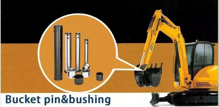
Casing application
The casing market is mainly driven by the growth of the power generation industry. The increasing electrification of Asia Pacific and the deployment of renewable energy in countries such as Saudi Arabia and the UAE are driving the demand for distribution transformer bushings. In addition, the demand for bushings in Western Europe is also likely to increase with the spread of renewable energy and the installation of electric vehicle charging infrastructure. However, the market in Asia Pacific is expected to remain small compared to the rest of the world.
Although bushings are relatively expensive, they are very durable and cost-effective. Furthermore, bushings have a variety of applications, making them an important component in power transformers. For example, power transformers often use bushings to achieve relative movement by sliding or rolling. The vehicle suspension system also uses rubber bushings for a smooth ride and rotating bushings for machine-related operations. They require precision machined parts and are especially useful in applications where high loads and friction must be controlled. Also, plastic bushings are used for wheels in dry kilns, where lubrication is often troublesome.
Transformers require constant monitoring, which is 1 of the reasons bushings are so important in power transformers. Any failure of these components could result in the total loss of the transformer and all surrounding equipment. To maintain high system reliability, utilities must monitor insulation in and around bushings, especially if transformers have been in use for decades. Some utilities have made monitoring the condition of their transformers an important part of their smart grid plans.
Material
The core of the dry casing has many material interfaces. The discharge most likely originates near the edges of the foils and can cause electrical tree growth or breakdown between adjacent foils. Several studies have investigated interfacial effects in composite insulating materials and concluded that the conditions under which the interface occurs is a key factor in determining the growth of electrical trees. This study found that material type and interface conditions are the 2 most important factors for the growth of electrical trees.
Bushings can be made of many different materials, depending on their purpose. The main purpose of the bushing is to support the assembly while protecting it. They must be stiff enough to support the load placed on them, and flexible enough to protect the shaft. Since the shaft is usually not centered on the bushing during rotation, the bushing must be durable enough to carry the load while still protecting the shaft. Here are several materials used for bushings:
A stabilizer bar assembly is a good example of pre-assembly. This pre-assembly enables the vehicle assembly plant to receive components ready for vehicle assembly. The prior art requires the vehicle assembly plant to separate the bushing from the stabilizer bar. However, the present invention eliminates this step and provides a mechanically rigid stabilizer bar assembly. It is designed to prevent audible squeals and improve vehicle performance and handling.
Hardened steel bushings are ideal for pivot and low speed applications. They are made of high carbon steel and fully hardened to 56-62 HRC. Bronze bushings require daily or weekly lubrication but are more expensive than plastic bushings. Plastic bushings are low cost, low maintenance, self lubricating and do not require regular lubrication. These are also suitable for applications with hard to reach parts.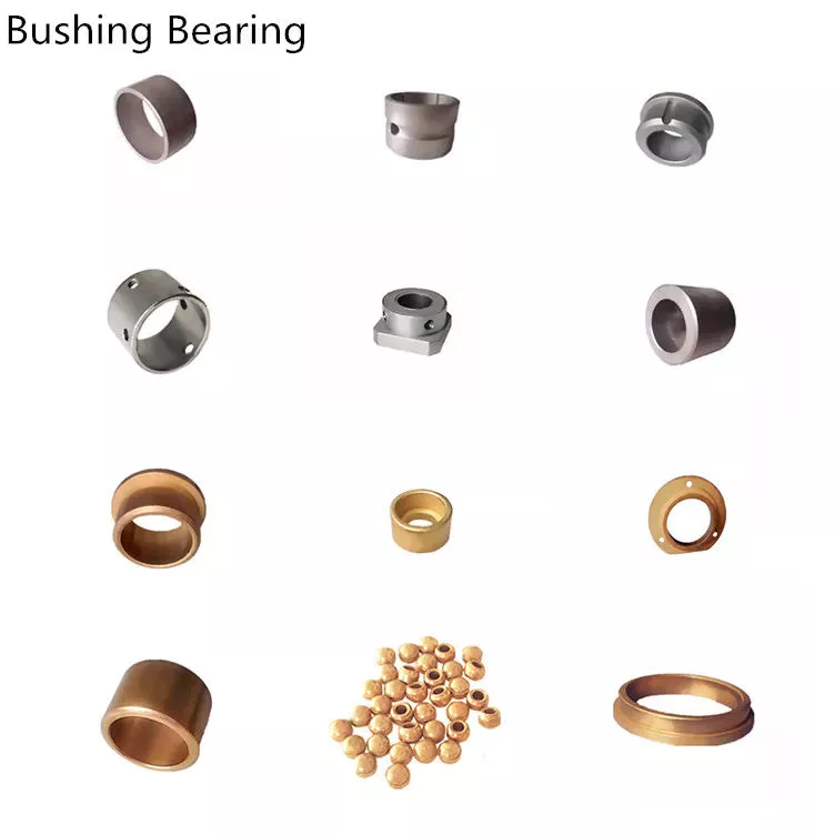
application
Bushings have many applications in various industries. Most of the time, it is used for drilling. Its excellent chemical and mechanical properties can be used to protect various equipment. These components are versatile and available in a variety of materials. All sleeves are packaged according to national and international standards. They are used in many industrial processes from construction to drilling. Some application examples are listed below.The component 10 may contain a tank for a liquid such as fuel, and the object 12 may be made of fiber reinforced composite material. Sleeve assembly 16 is configured to ground component 10 and object 12 . It may be a bulkhead isolator 40 used to isolate electrical charges in aircraft hydraulic lines. Bushing assembly 16 is 1 of many possible uses for the bushing assembly. The following examples illustrate various applications of bushing assemblies.
Bearings are devices used to reduce friction between moving surfaces. They are a good choice for many applications as they are maintenance free and extend the life of machine components. They can be used in a variety of applications and are often used with plastic and metal materials. For example, Daikin offers bronze and brass bushings. Bushings have many other uses, but they are most commonly used in machines, especially when used in low-load environments.
The most common application for bushings is drilling. Swivel bushings can be used in almost any drilling application. For more complex applications, CZPT's engineering department can create special designs to your specifications. The applications of bushings in machining centers are endless. By providing a smooth, reliable interface, bushings are an excellent choice for precision machining. They can also provide current paths.
Cost
When you have a vehicle that needs a bushing replacement, you may be wondering about the cost of a bushing replacement. The fact is, the cost of a bushing replacement will vary widely, depending on the specific car model. Some cars cost as little as $5, while other vehicles can cost up to $300. The replacement of a control arm bushing may not cost that much, but it's important to know that it's a relatively expensive part to replace.
Most mechanics charge around $375 for a job that involves replacing the bushing in a control arm. However, this price range can vary significantly, depending on whether the mechanic uses OE or aftermarket parts. In any case, the cost of labor is typically included in the price. Some mechanics may even include a labor charge, which is an additional cost. In general, however, the cost of a control arm bushing replacement is comparable to the cost of replacing a single bushing.
Control arm bushings are made of 2 metal cylinders secured together by a thick layer of rubber. Over time, these parts can deteriorate due to accidents, potholes, and off-roading. For this reason, it is important to replace them as soon as possible. Bushing replacement can save you money in the long run, and it's important to have your vehicle repaired as soon as possible. If your control arm bushing is showing signs of wear, you should have it replaced before it becomes completely useless.
If you have decided to replace your suspension bushing yourself, the cost will be considerably lower than you would spend on the replacement of other components. If you have a mechanically-inclined mechanic, you can do it yourself. The parts and labour are reasonably cheap, but the most expensive part is the labor. Because it requires disassembling the wheel and suspension and installing a new bushing, it is important to have a mechanic who has a good understanding of vehicle mechanicry. The cost for control arm bushing replacement is between $20 and $80 per bushing, and a set of 4 costs approximately $300.
Disambiguation
If you've come across a page containing information about Bushing, you may have been looking for more information. This disambiguation page lists publications about the person, but these have not been assigned to him. We encourage you to contact us if you know who the true author of these publications is. Nevertheless, if you're searching for specific information about Bushing, we recommend you start with CZPT.


China wholesaler Professional Technology Team Through Key Type Pneumatic Plastic Air Expanding Air Shaft For Printing Machine with Free Design Custom
Condition: New
Warranty: 6 Months
Applicable Industries: Manufacturing Plant, Machinery Restore Retailers, Retail, Printing Stores
Showroom Spot: None
Video outgoing-inspection: Presented
Machinery Check Report: Supplied
Advertising Sort: Ordinary Product
Warranty of main factors: 1 Yr
Main Elements: Bearing, Airbag
Framework: Spline
Substance: Aluminum, Metal
Coatings: Paper tube
Torque Potential: As necessary
Design Variety: KAIDE-KT
Kind: LUG/LEAF
Outer diameter: 3inch-12inches
Merchandise attribute: Customized
LUG Content: Rubber/Metal
Steel surface treatment: Hard chrome plating
Aluninum surface area treatment: HV700
Roll up wide blessing selection: 80mm+
Fat: 8kg+
Colour: white/brown
Bundle: Wood Instances
After Warranty Services: Movie technological assistance, On-line support
Nearby Service Location: None
Packaging Particulars: Wooden box
Port: ZheJiang
MODELDiameter without having aeration(ømm)Diameter after aeration(ømm)Suited internal diameter of reel pipe(ømm)1″ø24.8ø24.8-ø28ø25-ø261.5″ø37ø Manufacturing unit Supply Tailored Stainless Metal Cnc Machining Steel Part Tractor Bicycle Bicycle PTO Drive Shaft forty-ø42ø38-ø38.52″ø49ø52-ø54ø50-ø513″ø74-ø75ø80-ø82ø75.5-ø784″ø Very hot Sale Top quality Device Gear Box Casting Forged Irom Gearbox Reducer For Driving Motion ninety nine-ø100ø104-ø106ø101-ø1571″ø125ø130-ø133ø126-ø1286″ø150ø154-ø156ø151-ø1538″ China CZPT Truck Relationship Plate AZ9115311571 ø200ø206-ø264ø202-ø2571″ø250ø260-ø264ø252-ø25612″ø300ø308-ø310ø302-ø305
How to Identify a Faulty Travel Shaft
The most frequent issues associated with automotive driveshafts consist of clicking and rubbing noises. Even though driving, the noise from the driver's seat is often visible. An experienced automobile mechanic can effortlessly discover no matter whether the sound is coming from equally sides or from one side. If you recognize any of these symptoms, it truly is time to send your auto in for a appropriate analysis. Here's a guide to figuring out if your car's driveshaft is defective:
Signs and symptoms of Driveshaft Failure
If you're having difficulties turning your auto, it's time to check out your vehicle's driveshaft. A bad driveshaft can limit the overall manage of your vehicle, and you ought to fix it as quickly as feasible to avoid even more issues. Other indicators of a propshaft failure include peculiar noises from below the motor vehicle and trouble shifting gears. Squeaking from under the car is yet another sign of a defective driveshaft.
If your driveshaft fails, your vehicle will end. Even though the engine will still operate, the wheels will not flip. You could listen to unusual noises from under the automobile, but this is a exceptional symptom of a propshaft failure. Nonetheless, you will have loads of time to repair the issue. If you will not hear any sound, the problem is not impacting your vehicle's capacity to move.
The most apparent symptoms of a driveshaft failure are dull sounds, squeaks or vibrations. If the generate shaft is unbalanced, it is likely to hurt the transmission. It will call for a trailer to remove it from your car. Aside from that, it can also influence your car's efficiency and require repairs. So if you hear these indicators in your auto, be confident to have it checked by a mechanic correct away.
Generate shaft assembly
When developing a propshaft, the design must be primarily based on the torque necessary to drive the motor vehicle. When this torque is as well higher, it can trigger irreversible failure of the push shaft. Consequently, a very good generate shaft layout need to have a prolonged services life. Listed here are some suggestions to support you design and style a great driveshaft. Some of the major parts of the driveshaft are shown below.
Snap Ring: The snap ring is a removable component that secures the bearing cup assembly in the yoke cross hole. It also has a groove for locating the snap ring. Spline: A spline is a patented tubular machined component with a series of ridges that fit into the grooves of the mating piece. The bearing cup assembly is composed of a shaft and stop fittings.
U-joint: U-joint is necessary because of to the angular displacement amongst the T-formed housing and the pinion. This angle is especially big in elevated 4x4s. The style of the U-joint must promise a constant rotational speed. Appropriate driveshaft style should account for the difference in angular velocity amongst the shafts. The T-bracket and output shaft are attached to the bearing caps at the two finishes.
U-joint
Your vehicle has a established of U-joints on the driveshaft. If your vehicle requirements to be replaced, you can do it oneself. You will need to have a hammer, ratchet and socket. In purchase to eliminate the U-joint, you have to first get rid of the bearing cup. In some cases you will require to use a hammer to take away the bearing cup, you must be mindful as you do not want to damage the push shaft. If you cannot take away the bearing cup, you can also use a vise to press it out.
There are two varieties of U-joints. One particular is held by a yoke and the other is held by a c-clamp. A full ring is safer and ideal for vehicles that are frequently employed off-street. In some situations, a entire circle can be employed to mend a c-clamp u-joint.
In addition to abnormal torque, excessive hundreds and inappropriate lubrication are common brings about of U-joint failure. The U-joint on the driveshaft can also be ruined if the motor is modified. If you are driving a motor vehicle with a greatly modified motor, it is not ample to replace the OE U-joint. In this circumstance, it is essential to just take the time to appropriately lubricate these factors as essential to maintain them purposeful.
tube yoke
QU40866 Tube Yoke is a widespread substitute for damaged or destroyed driveshaft tubes. They are desirably created of a metallic substance, such as an aluminum alloy, and include a hollow portion with a lug framework at one particular stop. Tube yokes can be created using a selection of approaches, such as casting and forging. A frequent technique involves drawing solid factors and machining them into the final form. The ensuing components are significantly less high-priced to make, especially when when compared to other kinds.
The tube fork has a connection stage to the driveshaft tube. The lug structure provides attachment details for the gimbal. Normally, the driveshaft tube is 5 inches in diameter and the lug framework is 4 inches in diameter. The lug composition also serves as a mounting point for the generate shaft. After put in, Tube Yoke is simple to maintain. There are two sorts of lug constructions: a single is solid tube yoke and the other is welded.
Heavy-obligation series push shafts use bearing plates to safe the yoke to the U-joint. All other proportions are secured with exterior snap rings. Yokes are generally machined to accept U-bolts. For some programs, grease fittings are utilised. This attachment is a lot more suited for off-street automobiles and efficiency automobiles.
stop yoke
The end yoke of the push shaft is an integral component of the generate train. Deciding on a higher-top quality conclude yoke will help make sure long-phrase operation and stop untimely failure. Pat's Driveline provides a full line of automotive end yokes for electrical power get-offs, differentials and auxiliary equipment. They can also evaluate your current areas and give you with large high quality replacements.
A U-bolt is an industrial fastener with threaded legs. When used on a driveshaft, it supplies increased security in unstable terrain. You can purchase a U-bolt package to secure the pinion provider to the travel shaft. U-bolts also appear with lock washers and nuts. Performance automobiles and off-highway cars frequently use this sort of attachment. But just before you install it, you have to make sure the yoke is machined to accept it.
Conclude yokes can be produced of aluminum or metal and are created to supply strength. It also provides unique bolt styles for a variety of apps. CZPT's drivetrain is also stocked with a entire line of automotive flange yokes. The business also makes personalized flanged yokes for numerous well-known brand names. Because the firm has a comprehensive line of substitute flange yokes, it can assist you change your drivetrain from non-serviceable to serviceable.
bushing
The initial phase in repairing or changing an automotive driveshaft is to replace worn or damaged bushings. These bushings are positioned within the travel shaft to provide a smooth, protected experience. The shaft rotates in a rubber sleeve. If a bushing wants to be replaced, you need to initial verify the guide for tips. Some of these parts might also need to be changed, these kinds of as the clutch or swingarm.