Product Description
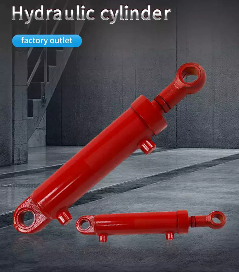
mini hydraulic cylinder price
Product Description
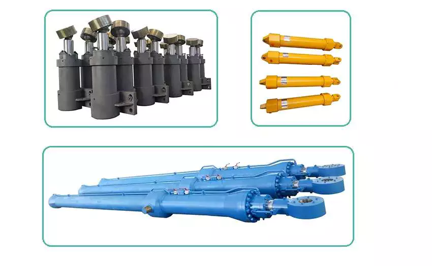
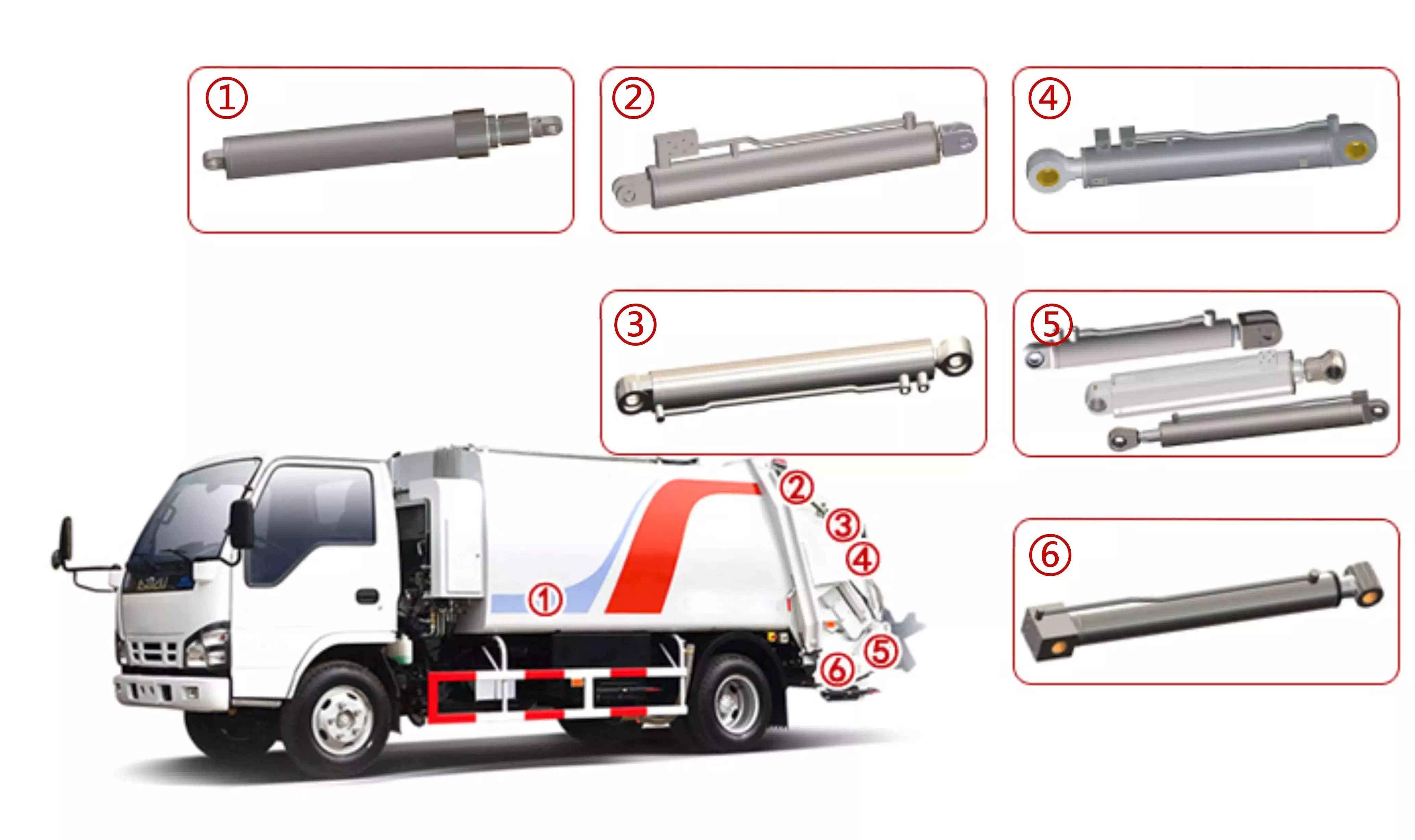
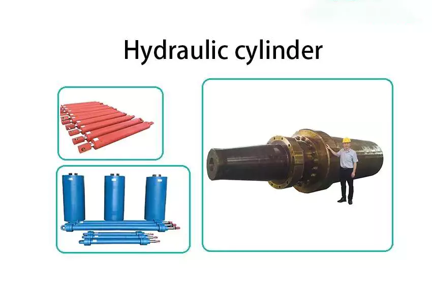
Eaton, parker, hercules, prince, cross type mini hydraulic cylinder jack are used for Trailer, Agricultural Machinery, Garbage Truck, Landing Platform etc.
Tsingshi hydraulic Customers, MAN, JAC, VOLVO, SHACMAN, DAF, JMC, HUNO, CIMC, SINOTRUK, TATRA,BENS,XIHU (WEST LAKE) DIS.FENG, FOTON,etc.
1.Piston rod electroplate hard chrome;
2.lighter and easier to maintenance hydraulic cylinder double acting 12v;
3.High quality alloy seamless steel pipe have better mechanical properties;
4.The world famous brands of seals, such as Parker, Merkel, Hallite, Kaden, etc;
5.World-class processing technology ensures stable and reliable quality.
| NO | ITEM | DATA of mini hydraulic cylinder price |
| 1 | Material | Carbon Steel, Alloy Steel, 27SiMn,45#,20#,etc |
| 2 | Honed tube | 40-300mm, Heat treatment, honing, rolling |
| 3 | Honed tube | 30-280mm, plated nickel or hard Chrome or ceramic |
| 4 | Seal kit | Parker, Merkel, Hallite, Kaden, etc |
| 5 | Coating | Sandblasting, primer paint, middle paint, finish paint, Color can paint according to customer demands. |
| 6 | Technology | double acting hydraulic cylinder |
| 7 | Mounting type | Pin-eye , flange, trunnion mount,ball mount, screw thread. FC, FE, FEE, FSE,TPIN |
| 8 | Working medium | Hydraulic Oil |
| 9 | Working pressure | 16-20Mpa mini hydraulic cylinders |
| 10 | Temperature range | -50°C to +100°C |
Detailed Photos
Company Profile
Tsingshi hydraulic is a hydraulic telescopic cylinder for dump tipper truck company which takes up with hydraulic design, R&D, manufacturer, sell and service hydraulic products- mini hydraulic cylinder price.
-double acting hydraulic cylinder Certification ISO9001 TS16949, etc;
-mini double acting hydraulic cylinder Export to North America, South America, Australia, South Korea, Southeast Asia, South Africa, Europe, Middle East, etc;
-ODM&OEM small double acting hydraulic cylinder according to client's requirements;
-Professional manufacturer& supplier of Hydraulic Cylinders over 30 years;
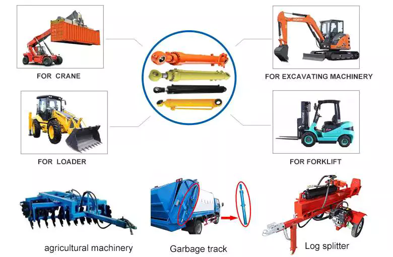
-The micro double acting hydraulic cylinder can be used for Dump Truck, Tipper Truck, Trailer, Agricultural Machinery, Garbage Truck,Landing Platform etc; We can produce the follow brand hydraulic cylinder. HYVA, BINOTTO, EDBRO, PENTA, MAILHOT, CUSTOM HOIST, MUNCIE, METARIS, HYDRAULEX GLOBAL, HYCO, PARKER, COMMERCIAL HYDRAULICS, MEILLER. WTJX, XT, JX, HCIC, ZX, SZ, SJ.
CUSTOMERS PHOTOS
QUALITY GUARANTEE
HIGH QUALITITY GUARANTEE- mini hydraulic cylinder price
-7*24 service.
-Competitive price.
-Professional technical team.
-Perfect after-sales service system.
-ODM&OEM Hydraulic Cylinder according to customer needs.
-Strong Hydraulic Cylinder production capacity to ensure fast delivery.
-Guarantee Quality. Every process must be inspected, all products need be tested before leaving the factory.
<hydraulic cylinder double acting Leak Test
<mini hydraulic cylinder Buffer Test
<small hydraulic cylinder Reliability Test
<micro hydraulic cylinder Full Stroke Test
<mini double acting hydraulic cylinder Operation Test
<micro double acting hydraulic cylinder Pressure Tight Test
<small double acting hydraulic cylinder Load Efficiency Test
<double action hydraulic cylinder Start-up Pressure Test
<hydraulic cylinder double acting 12v Testing the Effect of Limit
SALES AND SERVICE
PRODUCTS SERIES
ONE WORLD ONE LOVE
| Certification: | CE, ISO/Ts16949 |
|---|---|
| Pressure: | Medium Pressure |
| Work Temperature: | Normal Temperature |
| Acting Way: | Double Acting |
| Working Method: | Straight Trip |
| Adjusted Form: | Regulated Type |
| Samples: |
US$ 100/Piece
1 Piece(Min.Order) | |
|---|
| Customization: |
Available
|
|
|---|
How do hydraulic cylinders compare to other methods of force generation like electric motors?
Hydraulic cylinders and electric motors are two different methods of force generation with distinct characteristics and applications. While both hydraulic cylinders and electric motors can generate force, they differ in terms of their working principles, performance attributes, and suitability for specific applications. Here's a detailed comparison of hydraulic cylinders and electric motors:
1. Working Principle:
- Hydraulic Cylinders: Hydraulic cylinders generate force through the conversion of fluid pressure into linear motion. They consist of a cylinder barrel, piston, piston rod, and hydraulic fluid. When pressurized hydraulic fluid enters the cylinder, it pushes against the piston, causing the piston rod to extend or retract, thereby generating linear force.
- Electric Motors: Electric motors generate force through the conversion of electrical energy into rotational motion. They consist of a stator, rotor, and electromagnetic field. When an electrical current is applied to the motor's windings, it creates a magnetic field that interacts with the rotor, causing it to rotate and generate torque.
2. Force and Power:
- Hydraulic Cylinders: Hydraulic cylinders are known for their high force capabilities. They can generate substantial linear forces, making them suitable for heavy-duty applications that require lifting, pushing, or pulling large loads. Hydraulic systems can provide high force output even at low speeds, allowing for precise control over force application. However, hydraulic systems typically operate at lower speeds compared to electric motors.
- Electric Motors: Electric motors excel in providing high rotational speeds and are commonly used for applications that require rapid motion. While electric motors can generate significant torque, they tend to have lower force output compared to hydraulic cylinders. Electric motors are suitable for applications that involve continuous rotary motion, such as driving conveyor belts, rotating machinery, or powering vehicles.
3. Control and Precision:
- Hydraulic Cylinders: Hydraulic systems offer excellent control over force, speed, and positioning. By regulating the flow of hydraulic fluid, the force and speed of hydraulic cylinders can be precisely controlled. Hydraulic systems can provide gradual acceleration and deceleration, allowing for smooth and precise movements. This level of control makes hydraulic cylinders well-suited for applications that require precise positioning, such as in industrial automation or construction equipment.
- Electric Motors: Electric motors also offer precise control over speed and positioning. Through motor control techniques such as varying voltage, frequency, or pulse width modulation (PWM), the rotational speed and position of electric motors can be accurately controlled. Electric motors are commonly used in applications that require precise speed control, such as robotics, CNC machines, or servo systems.
4. Efficiency and Energy Consumption:
- Hydraulic Cylinders: Hydraulic systems can be highly efficient, especially when properly sized and designed. However, hydraulic systems typically have higher energy losses due to factors such as fluid leakage, friction, and heat generation. The overall efficiency of a hydraulic system depends on the design, component selection, and maintenance practices. Hydraulic systems require a hydraulic power unit to pressurize the hydraulic fluid, which consumes additional energy.
- Electric Motors: Electric motors can have high efficiency, especially when operated at their optimal operating conditions. Electric motors have lower energy losses compared to hydraulic systems, primarily due to the absence of fluid leakage and lower friction losses. The overall efficiency of an electric motor depends on factors such as motor design, load conditions, and control techniques. Electric motors require an electrical power source, and their energy consumption depends on the motor's power rating and the duration of operation.
5. Environmental Considerations:
- Hydraulic Cylinders: Hydraulic systems typically use hydraulic fluids that can pose environmental concerns if they leak or are not properly disposed of. The choice of hydraulic fluid can impact factors such as biodegradability, toxicity, and potential environmental hazards. Proper maintenance and leak prevention practices are essential to minimize the environmental impact of hydraulic systems.
- Electric Motors: Electric motors are generally considered more environmentally friendly since they do not require hydraulic fluids. However, the environmental impact of electric motors depends on the source of electricity used to power them. When powered by renewable energy sources, such as solar or wind, electric motors can offer a greener solution compared to hydraulic systems.
6. Application Suitability:
- Hydraulic Cylinders: Hydraulic cylinders are commonly used in applications that require high force output, precise control, and durability. They are widely employed in industries such as construction, manufacturing, mining, and aerospace. Hydraulic systems are well-suited for heavy-duty applications, such as lifting heavy objects, operating heavy machinery, or controlling large-scale movements.
- Electric Motors: Electric motors are widely used in various industries and applications that require rotational motion, speed control, and precise positioning. They are commonly found in appliances, transportation, robotics, HVAC systems, and automation. Electric motorsare suitable for applications that involve continuous rotary motion, such as driving conveyor belts, rotating machinery, or powering vehicles.In summary, hydraulic cylinders and electric motors have different working principles, force capabilities, control characteristics, efficiency levels, and application suitability. Hydraulic cylinders excel in providing high force output, precise control, and durability, making them ideal for heavy-duty applications. Electric motors, on the other hand, offer high rotational speeds, precise speed control, and are commonly used for applications that involve continuous rotary motion. The choice between hydraulic cylinders and electric motors depends on the specific requirements of the application, including the type of motion, force output, control precision, and environmental considerations.
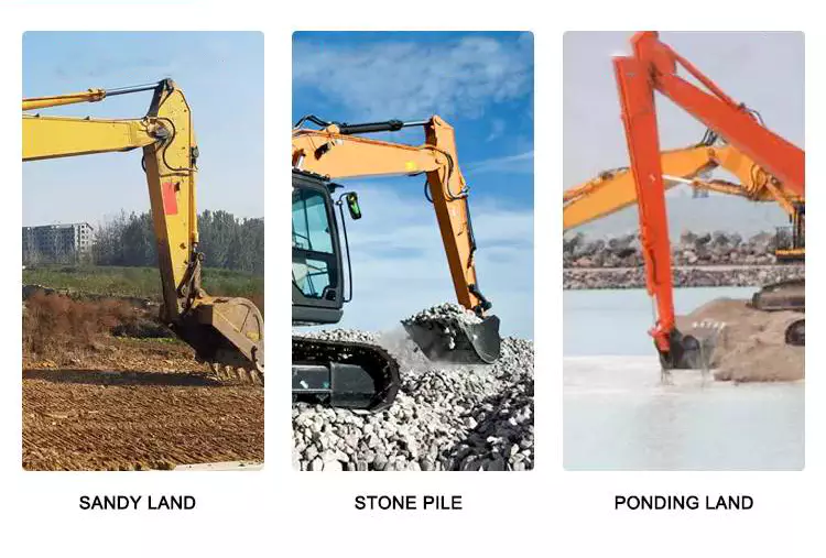
How do hydraulic cylinders contribute to the efficiency of agricultural tasks like plowing?
Hydraulic cylinders play a crucial role in improving the efficiency of agricultural tasks, including plowing. These cylinders provide several benefits that enhance the performance and productivity of agricultural machinery. Let's explore how hydraulic cylinders contribute to the efficiency of plowing and other agricultural tasks:
- Powerful Force Generation: Hydraulic cylinders are capable of generating high forces, which is essential for tasks like plowing. The hydraulic system supplies pressurized fluid to the cylinders, converting hydraulic energy into mechanical force. This force is then utilized to drive plow blades through the soil, overcoming resistance and facilitating efficient soil penetration. The power generated by hydraulic cylinders ensures effective plowing, even in tough or compacted soil conditions.
- Adjustable Working Depth: Hydraulic cylinders allow for easy and precise adjustment of the plow's working depth. By controlling the extension or retraction of the hydraulic cylinder, farmers can adjust the depth of the plow blades according to soil conditions, crop requirements, or their specific preferences. This adjustability enhances efficiency by ensuring optimal soil tillage and minimizing unnecessary energy expenditure. Farmers can adapt the plowing depth to different field areas, optimizing the use of resources and promoting uniform crop growth.
- Responsive Control: Hydraulic systems offer highly responsive control, enabling farmers to make quick adjustments during plowing operations. Hydraulic cylinders respond rapidly to changes in hydraulic pressure and valve settings, allowing for immediate modifications in the plow's position, depth, or angle. This responsiveness enhances efficiency by facilitating on-the-go adjustments based on soil variations, obstacles, or changing field conditions. Farmers can maintain precise control over the plow's performance, ensuring effective soil tillage and minimizing the risk of crop damage.
- Implement Versatility: Hydraulic cylinders enable the attachment of various implements to agricultural machinery, expanding their functionality and versatility. In the context of plowing, hydraulic cylinders allow for the attachment and detachment of plow blades or other tillage implements. This versatility enables farmers to adapt their equipment to different soil types, field sizes, or specific plowing requirements. By using hydraulic cylinders, farmers can easily switch between different implements, optimizing their equipment for specific tasks and maximizing efficiency.
- Efficient Time Management: Hydraulic cylinders contribute to time efficiency in agricultural tasks like plowing. With hydraulic systems, farmers can operate plows at higher speeds while maintaining control and precision. The responsive nature of hydraulic cylinders allows for efficient turning, maneuvering, and repositioning of plows, minimizing downtime and optimizing field coverage. This time efficiency translates into increased productivity and reduced overall operational costs. Farmers can accomplish plowing tasks more quickly, allowing them to cover larger field areas in less time.
In summary, hydraulic cylinders significantly contribute to the efficiency of agricultural tasks like plowing. Through powerful force generation, adjustable working depth, responsive control, implement versatility, and efficient time management, hydraulic systems equipped with cylinders enhance the performance and productivity of agricultural machinery. These contributions allow farmers to accomplish plowing tasks more effectively, optimize field operations, and achieve improved overall efficiency in their agricultural practices.
How do manufacturers ensure the quality and compatibility of hydraulic cylinders?
Manufacturers employ various measures to ensure the quality and compatibility of hydraulic cylinders, ensuring that they meet industry standards, performance requirements, and the specific needs of their customers. Here's a detailed explanation of the methods and practices used by manufacturers to ensure the quality and compatibility of hydraulic cylinders:
1. Design and Engineering:
- Manufacturers employ skilled engineers and designers who have expertise in hydraulic systems and cylinder design. They use advanced design software and tools to create hydraulic cylinders that meet the desired specifications and performance requirements. Through careful analysis and simulation, manufacturers can ensure that the cylinders are designed to function optimally and provide the necessary force, stroke length, and reliability.
2. Material Selection:
- High-quality materials are crucial for the durability, performance, and compatibility of hydraulic cylinders. Manufacturers carefully select materials such as steel or other alloys based on their strength, corrosion resistance, and suitability for hydraulic applications. They source materials from reputable suppliers and perform quality checks to ensure that the materials meet the required standards and specifications.
3. Quality Control:
- Manufacturers implement robust quality control processes throughout the production of hydraulic cylinders. This includes rigorous inspections and tests at various stages of manufacturing, from raw material inspection to final assembly. Quality control personnel perform dimensional checks, surface finish inspections, and functional tests to verify that the cylinders meet the specified tolerances, performance criteria, and compatibility requirements.
4. Testing and Validation:
- Hydraulic cylinders undergo testing and validation procedures to ensure their performance, reliability, and compatibility. Manufacturers conduct various tests, such as pressure testing, leakage testing, load testing, and endurance testing. These tests simulate real-world operating conditions and verify that the cylinders can withstand the expected loads, pressures, and environmental factors. Additionally, manufacturers may perform compatibility testing to ensure that the cylinders can integrate seamlessly with other hydraulic system components.
5. Compliance with Standards:
- Manufacturers adhere to industry standards and regulations to ensure the quality and compatibility of hydraulic cylinders. They follow standards such as ISO 9001 for quality management systems and ISO 6020/2 or ISO 6022 for hydraulic cylinders. Compliance with these standards ensures that the manufacturing processes, quality control measures, and product performance meet internationally recognized benchmarks.
6. Certification and Accreditation:
- Manufacturers may obtain certifications and accreditations from recognized organizations to demonstrate their commitment to quality and compatibility. Certifications such as ISO certifications or third-party certifications provide assurance to customers that the hydraulic cylinders have undergone rigorous evaluations and meet specific quality and compatibility standards.
7. Customer Collaboration:
- Manufacturers actively engage with customers to understand their specific requirements and ensure compatibility. They work closely with customers to gather application-specific details, such as operating conditions, load requirements, and environmental factors. This collaborative approach allows manufacturers to customize hydraulic cylinders and provide solutions that are perfectly matched to the customer's needs, ensuring compatibility and optimal performance.
8. Continuous Improvement:
- Manufacturers are committed to continuous improvement in their processes and products. They invest in research and development to incorporate the latest technologies, materials, and manufacturing techniques. By staying updated with industry advancements, manufacturers can enhance the quality, performance, and compatibility of their hydraulic cylinders over time.
By implementing effective design and engineering practices, selecting high-quality materials, conducting rigorous quality control, testing and validation procedures, complying with industry standards, obtaining certifications, collaborating with customers, and embracing continuous improvement, manufacturers ensure the quality and compatibility of hydraulic cylinders. These measures help to deliver reliable, high-performance cylinders that meet the diverse needs of industries and applications.

editor by CX 2023-11-09
China wholesaler 12" Stroke Double Acting Tie Rod Mini Hydraulic Oil Cylinder for Farm Tractor vacuum pump diy
Product Description
- Product Information
- Other Products
HangZhou GD Machinery CO.,LTD.
|
Product |
|
|
tie rod hydraulic cylinder, welded hydraulic cylinder, telescopic cylinders cylinder, flange type hydraulic cylinder, hydraulic cylinder with valve function, hydraulic power unit, Hydraulic manifold block, pneumatic fitting, |
|
|
Material |
Tube - Cold Drawn Precision seamless Tubing Mounts - Trunnion with angular Swivels |
|
Application |
Agriculture, Concrete & Asphalt, Cranes, Fire & Rescue, Forestry & Logging,Mining & Rock Crushing,Oil & Gas, Snow & Ice Control,Waste Management and Material Recycling Industry , Engineering Equipment, Special Vehicle |
|
Feature |
1.High quality with a reasonable price 2.ISO9001-2008 3.Customized specification are accepted |
|
Payment |
T/T;L/C, Paypal |
|
Port |
HangZhou ,China |
|
Quotation |
According to the specific request |
|
MOQ |
According to the product |
|
Packaging |
metal case;plywood case;carton or as requirement |
|
Delivery time |
30days upon receipt of 30% deposit; or upon receipt of relevant L/C; |
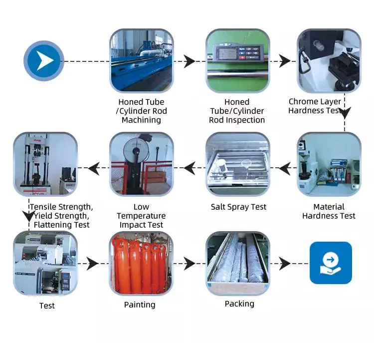
- Working Process
- Packing and Shipping
The products are fully protected by metal shelves, wood boxes and plastic fillers.
- Company Information
HangZhou GD Machinery is specialized to offer high precision all kind of hydraulic valves and hydraulic cylinder.we also have some hydraulic valve from CHINAMFG brand aboard
With a wide range, good quality ,reasonable price,our products are extensively used in the industries of construction machinery,machine tool,plastic machinery,vehicle. mining equipment,metallurgy,shipyard,food machinery,agricultural machinery,and other industries.
Our products are widely recognized and trusted by users and can meet continuously changing economic and social needs.
Welcome new and old customers to contact us for future business. we will offer you good quality and best price.
- Company Show
- Our Service
1. Sample service: samples will be provided according to customer's instruction.
2. Customized services: a variety of cylinders can be customized according to customer demand.
3. Warranty service: In case of quality problems under 1 year warranty period, free replacement will be made for customer.
- FAQ
Q: Do you accept OEM manufacturing?
A: Yes! We do accept OEM manufacturing. We will quote you the exact price and make the exact cylinder according to your specification and drawing.
Q: Can we design our own package or print our own logo?
A: Yes! Package and logo will be made acording to your requirements.
Q: Could we get small quantity samples?
A: Yes! We understand the quality test is important and we are glad to make the sample for you. The MOQ is 1pcs.
Q: How long is the production time?
A: Generally the production time is 30 days.
Q: What is your payment term?
A: For sample payment, generally 100% T/T payment in advance, west union, paypal.
For order payment, generally is 30% T/T in advance, 70% balance before shipment. If you require the different payment term, let us negotiate it together.
| Material: | Steel |
|---|---|
| Usage: | Construction Machine |
| Structure: | Piston Cylinder |
| Samples: |
US$ 60/Piece
1 Piece(Min.Order) | Order Sample |
|---|
| Customization: |
Available
|
|
|---|
.shipping-cost-tm .tm-status-off{background: none;padding:0;color: #1470cc}
| Shipping Cost:
Estimated freight per unit. |
about shipping cost and estimated delivery time. |
|---|
| Payment Method: |
|
|---|---|
|
Initial Payment Full Payment |
| Currency: | US$ |
|---|
| Return&refunds: | You can apply for a refund up to 30 days after receipt of the products. |
|---|
How do manufacturers ensure the durability and reliability of hydraulic cylinders?
Manufacturers employ various strategies and techniques to ensure the durability and reliability of hydraulic cylinders. These measures are crucial as hydraulic cylinders are often subjected to demanding operating conditions and heavy loads. To ensure their longevity and dependable performance, manufacturers focus on the following aspects:
1. High-Quality Materials:
- Manufacturers use high-quality materials in the construction of hydraulic cylinders. Components such as cylinder barrels, piston rods, seals, and bearings are made from materials that possess excellent strength, corrosion resistance, and wear resistance properties. Common materials used include high-grade steel alloys, chrome-plated rods, and specialized coatings. The selection of appropriate materials ensures that hydraulic cylinders can withstand the stresses, pressures, and environmental conditions they encounter during operation.
2. Robust Design:
- Hydraulic cylinders are designed to withstand high loads and harsh operating conditions. Manufacturers use computer-aided design (CAD) software and finite element analysis (FEA) techniques to optimize the cylinder's structural integrity and performance. The design includes factors such as proper wall thickness, reinforcement in critical areas, and appropriate sizing of components. Robust design practices ensure that hydraulic cylinders can withstand the forces and stresses they encounter, preventing premature failure and ensuring durability.
3. Quality Manufacturing Processes:
- Manufacturers follow stringent quality control measures during the manufacturing processes of hydraulic cylinders. These processes include precision machining, welding, heat treatment, and surface finishing. Skilled technicians and advanced machinery are employed to ensure dimensional accuracy, proper fitment of components, and overall quality. By adhering to strict manufacturing processes and quality standards, manufacturers can produce hydraulic cylinders with consistent performance and reliability.
4. Sealing Technology:
- The sealing system of hydraulic cylinders is critical for their durability and reliability. Manufacturers utilize advanced sealing technologies such as lip seals, O-rings, and composite seals to prevent fluid leakage and ingress of contaminants. Properly designed and high-quality seals ensure that hydraulic cylinders can maintain their performance over extended periods. Seals are tested for their compatibility with the hydraulic fluid, pressure resistance, and resilience to environmental factors such as temperature and humidity.
5. Performance Testing:
- Manufacturers subject hydraulic cylinders to rigorous performance testing to validate their durability and reliability. These tests simulate real-world operating conditions and evaluate factors such as load capacity, pressure resistance, fatigue life, and leakage. Performance testing helps identify any design flaws or weaknesses in the hydraulic cylinder and allows manufacturers to make necessary improvements. By conducting thorough performance testing, manufacturers can ensure that hydraulic cylinders meet or exceed the required performance standards.
6. Compliance with Industry Standards:
- Manufacturers adhere to industry standards and regulations to ensure the durability and reliability of hydraulic cylinders. These standards, such as ISO 6020/6022 and NFPA T3.6.7, provide guidelines for design, manufacturing, and performance requirements. By following these standards, manufacturers ensure that hydraulic cylinders are designed and built to meet specific quality and safety criteria. Compliance with industry standards helps establish a baseline for durability and reliability and instills confidence in the performance of hydraulic cylinders.
7. Regular Maintenance and Service:
- Manufacturers provide recommendations for regular maintenance and service of hydraulic cylinders. This includes guidelines for lubrication, inspection of components, and replacement of wear parts such as seals and bearings. Following the manufacturer's maintenance guidelines helps ensure the long-term durability and reliability of hydraulic cylinders. Regular maintenance also allows for the early detection of potential issues, preventing major failures and extending the service life of the hydraulic cylinders.
8. Customer Support and Warranty:
- Manufacturers provide customer support and warranty services to address any issues that arise with hydraulic cylinders. They offer technical assistance, troubleshooting guidance, and replacement of defective components. The warranty ensures that customers receive reliable and durable hydraulic cylinders and provides recourse in case of any manufacturing defects or premature failures. Strong customer support and warranty policies reflect the manufacturer's commitment to the durability and reliability of their products.
In summary, manufacturers ensure the durability and reliability of hydraulic cylinders through the use of high-quality materials, robust design practices, stringent manufacturing processes, advanced sealing technology, thorough performance testing, compliance with industry standards, regular maintenance guidelines, and customer support with warranty services. By focusing on these aspects, manufacturers can produce hydraulic cylinders that can withstand demanding conditions, provide long service life, and deliver reliable performance in various applications.
Adaptation of Hydraulic Cylinders for Medical Equipment and Aerospace Applications
Hydraulic cylinders have the potential to be adapted for use in medical equipment and aerospace applications, offering unique advantages in these industries. Let's explore how hydraulic cylinders can be adapted for these specialized fields:
- Medical Equipment: Hydraulic cylinders can be adapted for various medical equipment applications, including hospital beds, patient lifts, surgical tables, and rehabilitation devices. Here's how hydraulic cylinders are beneficial in medical equipment:
- Positioning and Adjustability: Hydraulic cylinders provide precise and smooth movement, allowing for accurate positioning and adjustments of medical equipment. This is crucial for ensuring patient comfort, proper alignment, and ease of use.
- Load Handling: Hydraulic cylinders offer high force capabilities, enabling the safe handling of heavy loads in medical equipment. They can support the weight of patients, facilitate smooth transitions, and provide stability during procedures.
- Controlled Motion: Hydraulic cylinders provide controlled and stable motion, which is essential for delicate medical procedures. The ability to adjust speed, position, and force allows for precise and controlled movements, minimizing patient discomfort and ensuring accurate treatment.
- Durability and Reliability: Hydraulic cylinders are designed to withstand rigorous use and demanding environments, making them suitable for medical equipment applications. Their durability and reliability contribute to the long-term performance and safety of medical devices.
- Aerospace Applications: Hydraulic cylinders can also be adapted for aerospace applications, where lightweight yet robust systems are essential. Here's how hydraulic cylinders are advantageous in aerospace:
- Flight Control Systems: Hydraulic cylinders play a critical role in aircraft flight control systems, including ailerons, elevators, rudders, and landing gear. They provide precise and reliable actuation, allowing pilots to control the aircraft's movements with accuracy and responsiveness.
- Weight Optimization: Hydraulic cylinders can be designed using lightweight materials, such as aluminum alloys or composite materials, to reduce overall weight. This weight optimization is crucial in aerospace applications to enhance fuel efficiency, payload capacity, and aircraft performance.
- Shock and Vibration Resistance: Aerospace environments involve significant shock and vibration forces. Hydraulic cylinders can be engineered to withstand these dynamic loads while maintaining performance and reliability, ensuring consistent operation even under extreme conditions.
- Space Constraints: Hydraulic cylinders can be designed to fit within the space constraints of aircraft or spacecraft. Their compact size and flexible mounting options allow for efficient integration into the limited available space.
In summary, hydraulic cylinders can be adapted for use in medical equipment and aerospace applications, leveraging their precise positioning, load handling capabilities, controlled motion, durability, and reliability. In medical equipment, hydraulic cylinders enable comfortable patient positioning, smooth transitions, and controlled movements during procedures. In aerospace, hydraulic cylinders provide precise actuation, weight optimization, shock and vibration resistance, and space-efficient solutions. By adapting hydraulic cylinders to these specialized fields, manufacturers can meet the unique requirements and enhance the performance of medical equipment and aerospace systems.
How do hydraulic cylinders generate force and motion using hydraulic fluid?
Hydraulic cylinders generate force and motion by utilizing the principles of fluid mechanics, specifically Pascal's law, in conjunction with the properties of hydraulic fluid. The process involves the conversion of hydraulic energy into mechanical force and linear motion. Here's a detailed explanation of how hydraulic cylinders achieve this:
1. Pascal's Law:
- Hydraulic cylinders operate based on Pascal's law, which states that when pressure is applied to a fluid in a confined space, it is transmitted equally in all directions. In the context of hydraulic cylinders, this means that when hydraulic fluid is pressurized, the force is evenly distributed throughout the fluid and transmitted to all surfaces in contact with the fluid.
2. Hydraulic Fluid and Pressure:
- Hydraulic systems use a specialized fluid, typically hydraulic oil, as the working medium. This fluid is stored in a reservoir and circulated through the system by a hydraulic pump. The pump pressurizes the fluid, creating hydraulic pressure that can be controlled and directed to various components, including hydraulic cylinders.
3. Cylinder Design and Components:
- Hydraulic cylinders consist of several key components, including a cylindrical barrel, a piston, a piston rod, and various seals. The barrel is a hollow tube that houses the piston and allows for fluid flow. The piston divides the cylinder into two chambers: the rod side and the cap side. The piston rod extends from the piston and provides a connection point for external loads. Seals are used to prevent fluid leakage and maintain hydraulic pressure within the cylinder.
4. Fluid Input and Motion:
- To generate force and motion, hydraulic fluid is directed into one side of the cylinder, creating pressure on the corresponding surface of the piston. This pressure is transmitted through the fluid to the other side of the piston.
5. Force Generation:
- The force generated by a hydraulic cylinder is a result of the pressure applied to a specific surface area of the piston. The force exerted by the hydraulic cylinder can be calculated using the formula: Force = Pressure × Area. The area is determined by the diameter of the piston or the piston rod, depending on which side of the cylinder the fluid is acting upon.
6. Linear Motion:
- As the pressurized hydraulic fluid acts on the piston, it generates a force that moves the piston in a linear direction within the cylinder. This linear motion is transferred to the piston rod, which extends or retracts accordingly. The piston rod can be connected to external components or machinery, allowing the generated force to perform various tasks, such as lifting, pushing, pulling, or controlling mechanisms.
7. Control and Regulation:
- The force and motion generated by hydraulic cylinders can be controlled and regulated by adjusting the flow of hydraulic fluid into the cylinder. By regulating the flow rate, pressure, and direction of the fluid, the speed, force, and direction of the cylinder's movement can be precisely controlled. This control allows for accurate positioning, smooth operation, and synchronization of multiple cylinders in complex machinery.
8. Return and Recirculation of Fluid:
- After the hydraulic cylinder completes its stroke, the hydraulic fluid on the opposite side of the piston needs to be returned to the reservoir. This is typically achieved through hydraulic valves that control the flow direction, allowing the fluid to return and be recirculated in the system for further use.
In summary, hydraulic cylinders generate force and motion by utilizing the principles of Pascal's law. Pressurized hydraulic fluid acts on the piston, creating force that moves the piston in a linear direction. This linear motion is transferred to the piston rod, allowing the generated force to perform various tasks. By controlling the flow of hydraulic fluid, the force and motion of hydraulic cylinders can be precisely regulated, contributing to their versatility and wide range of applications in machinery.
editor by CX 2023-11-08
China supplier Mini Stroke 200mm Piston Hydraulic Cylinder for Farm Tractor Harvester with Good quality
Product Description
small piston double acting hydraulic lift ram cylinder
Product Description
Eaton, parker, hercules, prince, cross type double acting hydraulic cylinder are used for Trailer, Agricultural Machinery, Garbage Truck, Landing Platform etc.
Tsingshi hydraulic Customers, MAN, JAC, VOLVO, SHACMAN, DAF, JMC, HUNO, CIMC, SINOTRUK, TATRA,BENS,XIHU (WEST LAKE) DIS.FENG, FOTON,etc.
1.Piston rod electroplate hard chrome;
2.lighter and easier to maintenance double acting hydraulic cylinder;
3.High quality alloy seamless steel pipe have better mechanical properties;
4.The world famous brands of seals, such as Parker, Merkel, Hallite, Kaden, etc;
5.World-class processing technology ensures stable and reliable quality.
| NO | ITEM | double acting hydraulic cylinder DATA |
| 1 | Material | Carbon Steel, Alloy Steel, 27SiMn,45#,20#,etc |
| 2 | Honed tube | 40-300mm, Heat treatment, honing, rolling |
| 3 | Honed tube | 30-280mm, plated nickel or hard Chrome or ceramic |
| 4 | Seal kit | Parker, Merkel, Hallite, Kaden, etc |
| 5 | Coating | Sandblasting, primer paint, middle paint, finish paint, Color can paint according to customer demands. |
| 6 | Technology | double acting hydraulic cylinder |
| 7 | Mounting type | Pin-eye , flange, trunnion mount,ball mount, screw thread. FC, FE, FEE, FSE,TPIN |
| 8 | Working medium | Hydraulic Oil |
| 9 | Working pressure | 16-20Mpa hydraulic lift cylinder |
| 10 | Temperature range | -50°C to +100°C |
Detailed Photos
Company Profile
Tsingshi hydraulic is a hydraulic telescopic cylinder for dump tipper truck company which takes up with hydraulic design, R&D, manufacturer, sell and service hydraulic products-small piston double acting hydraulic lift ram oil cylinder.
-double acting hydraulic cylinder Certification ISO9001 TS16949, etc;
-mini double acting hydraulic cylinder Export to North America, South America, Australia, South Korea, Southeast Asia, South Africa, Europe, Middle East, etc;
-ODM&OEM small double acting hydraulic cylinder according to client's requirements;
-Professional manufacturer& supplier of Hydraulic Cylinders over 30 years;
-The micro double acting hydraulic cylinder can be used for Dump Truck, Tipper Truck, Trailer, Agricultural Machinery, Garbage Truck,Landing Platform etc; We can produce the follow brand hydraulic cylinder. HYVA, BINOTTO, EDBRO, PENTA, MAILHOT, CUSTOM HOIST, MUNCIE, METARIS, HYDRAULEX GLOBAL, HYCO, PARKER, COMMERCIAL HYDRAULICS, MEILLER. WTJX, XT, JX, HCIC, ZX, SZ, SJ.
CUSTOMERS PHOTOS
QUALITY GUARANTEE
HIGH QUALITITY GUARANTEE-double acting hydraulic cylinder
-7*24 service.
-Competitive price.
-Professional technical team.
-Perfect after-sales service system.
-ODM&OEM Hydraulic Cylinder according to customer needs.
-Strong Hydraulic Cylinder production capacity to ensure fast delivery.
-Guarantee Quality. Every process must be inspected, all products need be tested before leaving the factory.
<hydraulic cylinder Leak Test
<piston hydraulic cylinder Buffer Test
<hydraulic lift cylinder Reliability Test
<hydraulic ram cylinder Full Stroke Test
<hydraulic cylinder double acting Operation Test
<micro double acting hydraulic cylinder Pressure Tight Test
<small double acting hydraulic cylinder Load Efficiency Test
<double action hydraulic cylinder Start-up Pressure Test
<double acting hydraulic cylinder Testing the Effect of Limit
SALES AND SERVICE
PRODUCTS SERIES
ONE WORLD ONE LOVE
| Certification: | CE, ISO/Ts16949 |
|---|---|
| Pressure: | Medium Pressure |
| Work Temperature: | Normal Temperature |
| Acting Way: | Double Acting |
| Working Method: | Straight Trip |
| Adjusted Form: | Regulated Type |
| Samples: |
US$ 100/Piece
1 Piece(Min.Order) | |
|---|
| Customization: |
Available
|
|
|---|
Are there any emerging trends in hydraulic cylinder technology, such as smart features?
Yes, there are several emerging trends in hydraulic cylinder technology, including the integration of smart features. As industries continue to adopt advanced technologies and seek greater efficiency, hydraulic cylinders are being equipped with innovative capabilities to enhance their performance and provide additional benefits. Here are some of the emerging trends in hydraulic cylinder technology:
1. Sensor Integration:
- One of the significant trends in hydraulic cylinder technology is the integration of sensors. Sensors can be embedded within the hydraulic cylinder to monitor various parameters such as pressure, temperature, position, and load. These sensors provide real-time data, allowing for condition monitoring, predictive maintenance, and improved operational control. By collecting and analyzing data, operators can optimize the performance of hydraulic systems, detect potential issues in advance, and prevent failures, resulting in increased reliability and reduced downtime.
2. Connectivity and IoT:
- Hydraulic cylinders are being integrated into the Internet of Things (IoT) ecosystem, enabling connectivity and data exchange. By connecting hydraulic cylinders to a network, operators can remotely monitor and control their performance. IoT-enabled hydraulic cylinders facilitate features such as remote diagnostics, performance optimization, and predictive maintenance. The connectivity aspect allows for better integration with overall equipment systems and enables data-driven decision-making for improved efficiency and productivity.
3. Energy-Efficient Designs:
- With the increasing focus on sustainability and energy efficiency, hydraulic cylinder technology is evolving to incorporate energy-saving features. Manufacturers are developing hydraulic cylinders with improved sealing technologies, reduced friction, and optimized fluid flow dynamics. These advancements minimize energy losses and increase overall system efficiency. Energy-efficient hydraulic cylinders contribute to reduced power consumption, lower operating costs, and a smaller environmental footprint.
4. Advanced Materials and Coatings:
- The use of advanced materials and coatings is another emerging trend in hydraulic cylinder technology. Manufacturers are exploring lightweight materials, such as composites and alloys, to reduce the overall weight of hydraulic cylinders without compromising strength and durability. Furthermore, specialized coatings and surface treatments are being applied to improve corrosion resistance, wear resistance, and lifespan. These advancements enhance the longevity and reliability of hydraulic cylinders, particularly in demanding environments.
5. Intelligent Control Systems:
- Hydraulic cylinder technology is embracing intelligent control systems that optimize performance and enable advanced functionalities. These systems utilize algorithms, machine learning, and artificial intelligence to automate processes, adapt to changing conditions, and optimize hydraulic cylinder movements. Intelligent control systems can adjust parameters in real-time, ensuring precise and efficient operation. This trend allows for increased automation, improved productivity, and enhanced safety in hydraulic system applications.
6. Predictive Maintenance:
- Predictive maintenance is gaining prominence in hydraulic cylinder technology. By utilizing data collected from sensors and monitoring systems, predictive maintenance algorithms can analyze the condition and performance of hydraulic cylinders. This analysis helps to identify potential failures or degradation in advance, enabling proactive maintenance actions. Predictive maintenance reduces unplanned downtime, extends the lifespan of hydraulic cylinders, and optimizes maintenance schedules, resulting in cost savings and improved equipment availability.
7. Enhanced Safety Features:
- Hydraulic cylinder technology is incorporating enhanced safety features to improve operator and equipment safety. These features include integrated safety valves, load monitoring systems, and emergency stop functionalities. Safety systems in hydraulic cylinders help prevent accidents, protect against overloads, and ensure reliable operation. The integration of advanced safety features contributes to safer working environments and compliance with stringent safety regulations.
These emerging trends in hydraulic cylinder technology demonstrate the industry's focus on innovation, performance optimization, and sustainability. The integration of smart features, connectivity, advanced materials, and predictive maintenance capabilities enables hydraulic cylinders to operate more efficiently, provide real-time insights, and enhance overall system performance. As technology continues to advance, hydraulic cylinder technology is expected to evolve further, offering increased functionality and efficiency for various industries and applications.
Contribution of Hydraulic Cylinders to the Precision of Robotic and Automation Systems
Hydraulic cylinders play a significant role in enhancing the precision of robotic and automation systems. These systems rely on precise and controlled movements to perform various tasks with accuracy and repeatability. Let's explore how hydraulic cylinders contribute to the precision of robotic and automation systems:
- Precise Positioning: Hydraulic cylinders enable precise positioning of robotic arms or automation components. They provide accurate control over the linear motion required for tasks such as picking, placing, and assembly. By precisely controlling the extension and retraction of the hydraulic cylinder, the system can achieve the desired position with high accuracy, ensuring precise alignment and consistent results.
- Controlled Motion: Hydraulic cylinders offer controlled and smooth motion, which is crucial for precise operation in robotic and automation systems. The flow of hydraulic fluid can be precisely regulated to control the speed and acceleration of the cylinder's movement. This precise control allows for gentle and controlled movements, minimizing vibrations, overshooting, or jerky motions that could affect the accuracy of the system.
- Force Control: Hydraulic cylinders provide force control capabilities that contribute to precision in robotic and automation systems. By adjusting the hydraulic pressure, the force exerted by the cylinder can be precisely controlled. This is particularly valuable in applications that require delicate force-sensitive tasks, such as gripping fragile objects or performing precise force feedback during assembly or testing processes.
- Load Handling: Hydraulic cylinders are capable of handling heavy loads, allowing robotic and automation systems to manipulate and transport objects with precision. The high force capabilities of hydraulic cylinders ensure secure and stable handling of loads, minimizing the risk of slippage or imprecise positioning. This is crucial in applications where precise control over heavy objects is required, such as material handling or industrial assembly processes.
- Durability and Reliability: Hydraulic cylinders are known for their durability and reliability in demanding industrial environments. The ability to withstand repeated use, high loads, and harsh conditions ensures consistent performance over time. This reliability contributes to the precision of robotic and automation systems, as any deviation or failure in the cylinder's movement could lead to inaccuracies or disruptions in the system's operation.
In summary, hydraulic cylinders make significant contributions to the precision of robotic and automation systems by enabling precise positioning, controlled motion, force control, load handling, and offering durability and reliability. These capabilities ensure accurate and repeatable movements, minimize errors, and enhance the overall precision of the system. By incorporating hydraulic cylinders into robotic and automation systems, manufacturers can achieve higher levels of precision, efficiency, and productivity in various industrial applications.
What safety precautions should be followed when working with hydraulic cylinders?
Working with hydraulic cylinders requires strict adherence to safety precautions to prevent accidents, injuries, and damage to equipment or property. Hydraulic systems operate under high pressures and involve moving parts, which can pose serious hazards if not handled properly. Here's a detailed explanation of the safety precautions that should be followed when working with hydraulic cylinders:
1. Training and Knowledge:
- Ensure that personnel working with hydraulic cylinders have received adequate training and possess a thorough understanding of hydraulic system operation, maintenance, and safety protocols. Proper training should cover topics such as hydraulic principles, pressure ratings, safe work practices, and emergency procedures. Only trained and authorized personnel should be allowed to handle hydraulic cylinders.
2. Wear Personal Protective Equipment (PPE):
- Always wear appropriate personal protective equipment when working with hydraulic cylinders. This may include safety glasses, gloves, protective clothing, and steel-toed boots. PPE helps protect against potential hazards, such as hydraulic fluid leaks, flying debris, or accidental contact with moving parts.
3. Hydraulic System Inspection:
- Before working with hydraulic cylinders, inspect the entire hydraulic system for any signs of damage, leaks, or loose connections. Check hydraulic hoses, fittings, valves, and cylinders for integrity and secure fastening. If any issues are detected, the system should be repaired or serviced before operation.
4. Relieve Pressure:
- Before performing any maintenance or disassembly on a hydraulic cylinder, it is crucial to relieve the pressure in the system. Follow the manufacturer's instructions to properly release pressure and ensure that the hydraulic cylinder is depressurized before starting any work. Failure to do so can result in sudden and uncontrolled movement of the cylinder or hydraulic lines, leading to serious injuries.
5. Lockout/Tagout Procedures:
- Implement lockout/tagout procedures to prevent accidental energization of the hydraulic system while maintenance or repair work is being conducted. Lockout/tagout involves isolating the energy source, such as shutting off the hydraulic pump and locking or tagging the controls to prevent unauthorized operation. This procedure ensures that the hydraulic cylinder remains in a safe, non-operational state during maintenance activities.
6. Use Proper Lifting Techniques:
- When working with heavy hydraulic cylinders or components, use proper lifting techniques and equipment to avoid strain or injury. Hydraulic cylinders can be heavy and awkward to handle, so ensure that lifting equipment, such as cranes or hoists, is properly rated and used correctly. Follow safe lifting practices, including securing the load and maintaining a stable lifting posture.
7. Hydraulic Fluid Handling:
- Handle hydraulic fluid with care and follow proper procedures for fluid filling, transfer, and disposal. Avoid contact with the skin or eyes, as hydraulic fluid may be hazardous. Use appropriate containers and equipment to prevent spills or leaks. If any hydraulic fluid comes into contact with the skin or eyes, rinse thoroughly with water and seek medical attention if necessary.
8. Regular Maintenance:
- Perform regular maintenance and inspections on hydraulic cylinders to ensure their safe and reliable operation. This includes checking for leaks, inspecting seals, monitoring fluid levels, and conducting periodic servicing as recommended by the manufacturer. Proper maintenance helps prevent unexpected failures and ensures the continued safe use of hydraulic cylinders.
9. Follow Manufacturer Guidelines:
- Always follow the manufacturer's guidelines, instructions, and recommendations for the specific hydraulic cylinders and equipment being used. Manufacturers provide important safety information, maintenance schedules, and operational guidelines that should be strictly adhered to for safe and optimal performance.
10. Emergency Preparedness:
- Be prepared for potential emergencies by having appropriate safety equipment, such as fire extinguishers, first aid kits, and emergency eyewash stations, readily available. Establish clear communication channels and emergency response procedures to promptly address any accidents, leaks, or injuries that may occur during hydraulic cylinder operations.
By following these safety precautions, individuals working with hydraulic cylinders can minimize the risk of accidents, injuries, and property damage. It is essential to prioritize safety, maintain awareness of potential hazards, and ensure compliance with relevant safety regulations and industry standards.
editor by CX 2023-10-29
China Hot selling for Farm Mini Tractors Small Pto Shaft Agricultural Sale 4X4 in Grass Machine Crawler El Salvador Petrol Engine Garden Tractor
Product Description
| Size | 260 cm * 120 cm * 135 cm |
| Drive Wheel | 4WD |
| Power | 12(Kw) |
| Specification | 30-50HP |
| Fuel | Gas / Diesel |
| Weight | 680(kg) |
| Tyres sizes | 500-12/650-16 |
| Usage | Farm Tractor, Garden Tractor, Lawn Tractor |
This is part of the certificate, please contact us if you need more!
We can provide customers with customizable packaging, a large number of goods in stock, and a wide choice of freight routes.
Q1: Can I have a sample order?
A1: Yes, we accept sample order to test and check quality.
Q2: Do you have MOQ limit?
A2: Yes, we have MOQ limit for mass production, but it depends on model. Please contact us for details.
Q3: How about the lead time?
A3: Samples will takes 5-7 business days. Mass production will takes 25-30 days. It depends on quantity.
Q4: How about shipping and delivery time?
A4: Generally, Item will be shipped via Express, such as DHL, TNT, FedEx and UPS, delivery time is 3-7 business days. Airline and sea shipping also available.
In order to better serve customers, we now make the following disclaimer for the product information published on the website that contains text, pictures, and links:
1. The product picture may have a color difference with the actual product due to the different angle and light, as well as the display difference of the monitor. The picture is for reference only, the actual product shall prevail, please contact our staff for more details.
2. It is the customized product, not final retail product. Details, description, pictures, and specifications are subject to the final confirmed order.
3. The price is for reference only, the market price is fluctuating, and the price marked on this page is not the only basis for the final transaction. Please contact our sales staff to confirm the final price.
|
Shipping Cost:
Estimated freight per unit. |
To be negotiated |
|---|
| After-sales Service: | 6 Months |
|---|---|
| Warranty: | 6 Months |
| Type: | Wheel Tractor |
| Samples: |
US$ 16999/Piece
1 Piece(Min.Order) | Order Sample |
|---|
| Customization: |
Available
| Customized Request |
|---|

How do manufacturers ensure the compatibility of PTO shafts with different equipment?
Manufacturers employ various measures to ensure the compatibility of PTO (Power Take-Off) shafts with different equipment. Compatibility is crucial to ensure that PTO shafts can effectively transfer power from the power source to the driven machinery without compromising performance, safety, or ease of use. Here's a detailed explanation of how manufacturers ensure compatibility:
1. Standardization: PTO shafts are designed and manufactured based on standardized specifications. These specifications outline the essential parameters such as shaft dimensions, spline sizes, torque ratings, and safety requirements. By adhering to standardized designs, manufacturers ensure that PTO shafts are compatible with a wide range of equipment that meets the same standards. Standardization allows for interchangeability, meaning that PTO shafts from one manufacturer can be used with equipment from another manufacturer as long as they conform to the same specifications.
2. Collaboration with Equipment Manufacturers: PTO shaft manufacturers often collaborate closely with equipment manufacturers to ensure compatibility. They work together to understand the specific requirements of the equipment and design PTO shafts that seamlessly integrate with the machinery. This collaboration may involve sharing technical specifications, conducting joint testing, and exchanging feedback. By working in partnership, manufacturers can address any compatibility issues early in the design and development process, resulting in PTO shafts that are tailored to the equipment's needs.
3. Customization Options: PTO shaft manufacturers offer customization options to accommodate different equipment configurations. They provide flexibility in terms of shaft length, spline sizes, yoke designs, and coupling mechanisms. Equipment manufacturers can specify the required parameters, and the PTO shafts can be customized accordingly. This ensures that the PTO shafts precisely match the equipment's power input/output requirements and connection methods, guaranteeing compatibility and efficient power transfer.
4. Testing and Validation: Manufacturers conduct rigorous testing and validation processes to ensure the compatibility and performance of PTO shafts. They subject the shafts to various tests, including torque testing, rotational speed testing, and durability testing. These tests verify that the PTO shafts can handle the expected power loads and operating conditions without failure. By validating the performance of the PTO shafts, manufacturers can ensure that they are compatible with a wide range of equipment and can reliably transfer power under different operating scenarios.
5. Compliance with Industry Standards: PTO shaft manufacturers adhere to industry standards and regulations to ensure compatibility. Organizations such as the American Society of Agricultural and Biological Engineers (ASABE) establish safety and performance standards for PTO shafts. Manufacturers design and produce their shafts in accordance with these standards, ensuring that their products meet the necessary requirements for compatibility and safety. Compliance with industry standards provides assurance to equipment manufacturers and end-users that the PTO shafts are compatible and suitable for use with different equipment.
6. Documentation and Guidelines: Manufacturers provide comprehensive documentation and guidelines to assist equipment manufacturers and end-users in ensuring compatibility. This documentation includes technical specifications, installation instructions, maintenance guidelines, and safety recommendations. The documentation helps equipment manufacturers select the appropriate PTO shaft for their equipment and provides guidance on proper installation and use. By following the manufacturer's guidelines, equipment manufacturers can ensure compatibility and optimize the performance of the PTO shafts.
7. Ongoing Research and Development: PTO shaft manufacturers continuously invest in research and development to enhance compatibility with different equipment. They stay updated with industry trends, technological advancements, and evolving equipment requirements. This ongoing research and development enable manufacturers to improve the design, materials, and features of PTO shafts, ensuring compatibility with the latest equipment innovations and addressing any compatibility challenges that may arise.
By employing standardization, collaborating with equipment manufacturers, offering customization options, conducting thorough testing, complying with industry standards, providing documentation and guidelines, and investing in research and development, manufacturers ensure the compatibility of PTO shafts with different equipment. This compatibility allows for seamless integration, efficient power transfer, and optimal performance across a wide range of machinery and equipment in various industries.

Can PTO shafts be customized for specific machinery and power requirements?
Yes, PTO (Power Take-Off) shafts can be customized to meet the specific machinery and power requirements of different applications. Manufacturers offer customization options to ensure that PTO shafts are precisely tailored to the power source, driven machinery, and the intended application. Here's a detailed explanation of how PTO shafts can be customized:
1. Shaft Length: PTO shafts can be customized in terms of length to accommodate different equipment configurations. The length of the PTO shaft is critical to ensure proper alignment and connection between the power source and driven machinery. Manufacturers can provide PTO shafts with adjustable or fixed-length options, allowing for flexibility in meeting specific length requirements. Customizing the shaft length ensures that the PTO shaft fits the equipment properly, optimizing power transfer efficiency and reducing the risk of misalignment or excessive stress.
2. Spline Sizes: PTO shafts are available with different spline sizes to match the input and output shafts of various equipment. Spline size customization allows the PTO shaft to seamlessly connect to the power source and driven machinery. Manufacturers can offer different spline configurations, such as 1-3/8 inch, 1-3/4 inch, or metric sizes, to accommodate specific machinery requirements. Customizing the spline size ensures a proper fit and secure connection, enabling efficient power transfer without the need for additional adapters or modifications.
3. Yoke Designs: PTO shafts can be customized with different yoke designs to match the connection points on the power source and driven machinery. The yoke is the component that attaches to the shaft and connects to the equipment. Manufacturers can provide various yoke designs, such as round, triangular, or splined yokes, to ensure compatibility with specific machinery. Customizing the yoke design allows for a secure and reliable connection, aligning the PTO shaft with the equipment's input/output shafts and optimizing power transmission efficiency.
4. Torque Ratings: PTO shafts can be customized to handle specific torque requirements based on the power demands of the application. Torque is the rotational force that the PTO shaft needs to transmit from the power source to the driven machinery. Manufacturers can design PTO shafts with different torque ratings by using appropriate materials, dimensions, and reinforcement techniques. Customizing the torque rating ensures that the PTO shaft can safely and reliably handle the required power levels without premature wear or failure.
5. Coupling Mechanisms: PTO shafts can be customized with different coupling mechanisms to match the connection requirements of specific equipment. Coupling mechanisms are the means by which the PTO shaft connects and disconnects from the power source and driven machinery. Manufacturers can provide various coupling options, such as quick-release couplings, shear pin couplings, or mechanical lock couplings, to accommodate different machinery designs and operational needs. Customizing the coupling mechanism ensures ease of use, secure attachment, and quick disengagement when necessary.
6. Protective Features: PTO shafts can be customized with additional protective features to enhance safety and durability. These features may include guard shields, safety covers, or slip clutches. Guard shields and safety covers provide physical protection by enclosing the rotating shaft and preventing accidental contact, reducing the risk of injuries. Slip clutches offer overload protection by allowing the PTO shaft to slip or disengage when excessive torque or resistance is encountered, preventing damage to the shaft and associated equipment. Customizing the protective features ensures compliance with safety regulations and addresses specific safety requirements of the machinery or application.
7. Material Selection: PTO shafts can be customized with different materials based on the application's demands. Manufacturers can offer a range of material options, such as steel, aluminum, or composite materials, with varying strength, weight, and corrosion resistance properties. Customizing the material selection allows for optimizing the PTO shaft's performance, considering factors like operating conditions, environmental exposure, and weight restrictions.
By providing customization options such as shaft length, spline sizes, yoke designs, torque ratings, coupling mechanisms, protective features, and material selection, manufacturers can ensure that PTO shafts are specifically tailored to meet the machinery and power requirements of different applications. Customized PTO shafts facilitate seamless integration, efficient power transfer, and reliable operation, enhancing the overall performance and productivity of the equipment.

Can you explain the different types of PTO shafts and their applications?
PTO shafts (Power Take-Off shafts) come in various types, each designed for specific applications and requirements. The different types of PTO shafts offer versatility and compatibility with a wide range of machinery and implements. Here's an explanation of the most common types of PTO shafts and their applications:
1. Standard PTO Shaft: The standard PTO shaft, also known as a splined shaft, is the most common type used in agricultural and industrial machinery. It consists of a solid steel shaft with splines or grooves along its length. The standard PTO shaft typically has six splines, although variations with four or eight splines can be found. This type of PTO shaft is widely used in tractors and various implements, including mowers, balers, tillers, and rotary cutters. The splines provide a secure connection between the power source and the driven machinery, ensuring efficient power transfer.
2. Shear Bolt PTO Shaft: Shear bolt PTO shafts are designed with a safety feature that allows the shaft to separate in case of overload or sudden shock to protect the driveline components. These PTO shafts incorporate a shear bolt mechanism that connects the tractor's power take-off to the driven machinery. In the event of excessive load or sudden resistance, the shear bolt is designed to break, disconnecting the PTO shaft and preventing damage to the driveline. Shear bolt PTO shafts are commonly used in equipment that may encounter sudden obstructions or high-stress situations, such as wood chippers, stump grinders, and heavy-duty rotary cutters.
3. Friction Clutch PTO Shaft: Friction clutch PTO shafts feature a clutch mechanism that allows for smooth engagement and disengagement of the power transfer. These PTO shafts typically incorporate a friction disc and a pressure plate, similar to a traditional vehicle clutch system. The friction clutch allows operators to gradually engage or disengage the power transfer, reducing shock loads and minimizing wear on the driveline components. Friction clutch PTO shafts are commonly used in applications where precise control of power engagement is required, such as in hydraulic pumps, generators, and industrial mixers.
4. Constant Velocity (CV) PTO Shaft: Constant Velocity (CV) PTO shafts, also known as homokinetic shafts, are designed to accommodate high angles of misalignment without affecting power transmission. They use a universal joint mechanism that allows for smooth power transfer even when the driven machinery is at an angle relative to the power source. CV PTO shafts are frequently used in applications where the machinery requires a significant range of movement or articulation, such as in articulated loaders, telescopic handlers, and self-propelled sprayers.
5. Telescopic PTO Shaft: Telescopic PTO shafts are adjustable in length, allowing for flexibility in equipment configuration and varying distances between the power source and the driven machinery. They consist of two or more concentric shafts that slide within each other, providing the ability to extend or retract the PTO shaft as needed. Telescopic PTO shafts are commonly used in applications where the distance between the tractor's power take-off and the implement varies, such as in front-mounted implements, snow blowers, and self-loading wagons. The telescopic design enables easy adaptation to different equipment setups and minimizes the risk of the PTO shaft dragging on the ground.
6. Gearbox PTO Shaft: Gearbox PTO shafts are designed to adapt power transmission between different rotational speeds or directions. They incorporate a gearbox mechanism that allows for speed reduction or increase, as well as the ability to change rotational direction. Gearbox PTO shafts are commonly used in applications where the driven machinery requires a different speed or rotational direction than the tractor's power take-off. Examples include grain augers, feed mixers, and industrial equipment that requires specific speed ratios or reversing capabilities.
It's important to note that the availability and specific applications of PTO shaft types may vary based on regional and industry-specific factors. Additionally, certain machinery or implements may require specialized or custom PTO shafts to meet specific requirements.
In summary, the different types of PTO shafts, such as standard, shear bolt, friction clutch, constant velocity (CV), telescopic, and gearbox shafts, offer versatility and compatibility with various machinery and implements. Each type of PTO shaft is designed to address specific needs, such as power transfer efficiency, safety, smooth engagement, misalignment tolerance, adaptability, and speed/direction adjustment. Understanding the different types of PTO shafts and their applications is crucial for selecting the appropriate shaft forthe intended machinery and ensuring optimal performance and reliability.

editor by CX 2023-09-14
China high quality Anon High Quality 50HP Farm Tractor Wheel Loader Mini Backhoe Loader near me manufacturer
Product Description
ANON High Quality 50HP Farm Tractor Wheel Loader Mini Backhoe Loader
1.It is used for ditching in farms and grazing lands,digging pool,cleaning waterways as well as assistant excavating work in construction and building roads.
2.Hydraulic transmission is used,Featured with compact structure, flexibility, convenient operation and quick mounting and dismounting.
3.It uses hydraulic oil commonly with tractor. The hydraulic elements are standardized, convenient for operation and service.
Specification of 4*4 wheel 40hp tractor with front end loader and backhoe
| Model | LW-6 | LW-7 | LW-8 | LW-9 |
| Tractor HP | 25-30HP | 30-45HP | 45-60HP | 60-80HP |
| 3-Point Linkage | Cat-1 | Cat-1&2 | ||
| Structure Weight | 480kgs | 500kgs | 580kgs | 620kgs |
| Digging Depth(Two foot flat bottom) | 1750mm | 1950mm | 2250mm | 2550mm |
| Reach from center line of Swing Pivot | 2600mm | 2900mm | 3200mm | 3600mm |
| Loading Height(bucket at 60 degree) | 1720mm | 1840mm | 1930mm | 2210mm |
| Transport Height(MAX) | 1840mm | 2060mm | 2130mm | 2480mm |
| Extend Height | 2870mm | 3110mm | 3240mm | 3590mm |
| Loading Reach(bucket at 60degree) | 950mm | 1180mm | 1140mm | 1360mm |
| Transport Overhang | 1080mm | 1110mm | 1220mm | 1270mm |
| Undercut | 730mm | 830mm | 470mm | 520mm |
| Bucket Rotation | 180degree | |||
| Stabilizer Spread(up position) | 1310mm | 1310mm | 1310mm | 1310mm |
| Stabilizer Spread(down position) | 2100mm | 2100mm | 2340mm | 2340mm |
| Swing Arc | 180 degree | |||
| Bucket Width | 300mm | 400mm | 450mm | 500mm |
| Bucket Cubage | 0.036 | 0.045 | 0.052 | 0.063 |
Applications of Spline Couplings
A spline coupling is a highly effective means of connecting 2 or more components. These types of couplings are very efficient, as they combine linear motion with rotation, and their efficiency makes them a desirable choice in numerous applications. Read on to learn more about the main characteristics and applications of spline couplings. You will also be able to determine the predicted operation and wear. You can easily design your own couplings by following the steps outlined below.
Optimal design
The spline coupling plays an important role in transmitting torque. It consists of a hub and a shaft with splines that are in surface contact without relative motion. Because they are connected, their angular velocity is the same. The splines can be designed with any profile that minimizes friction. Because they are in contact with each other, the load is not evenly distributed, concentrating on a small area, which can deform the hub surface.
Optimal spline coupling design takes into account several factors, including weight, material characteristics, and performance requirements. In the aeronautics industry, weight is an important design factor. S.A.E. and ANSI tables do not account for weight when calculating the performance requirements of spline couplings. Another critical factor is space. Spline couplings may need to fit in tight spaces, or they may be subject to other configuration constraints.
Optimal design of spline couplers may be characterized by an odd number of teeth. However, this is not always the case. If the external spline's outer diameter exceeds a certain threshold, the optimal spline coupling model may not be an optimal choice for this application. To optimize a spline coupling for a specific application, the user may need to consider the sizing method that is most appropriate for their application.
Once a design is generated, the next step is to test the resulting spline coupling. The system must check for any design constraints and validate that it can be produced using modern manufacturing techniques. The resulting spline coupling model is then exported to an optimisation tool for further analysis. The method enables a designer to easily manipulate the design of a spline coupling and reduce its weight.
The spline coupling model 20 includes the major structural features of a spline coupling. A product model software program 10 stores default values for each of the spline coupling's specifications. The resulting spline model is then calculated in accordance with the algorithm used in the present invention. The software allows the designer to enter the spline coupling's radii, thickness, and orientation.
Characteristics
An important aspect of aero-engine splines is the load distribution among the teeth. The researchers have performed experimental tests and have analyzed the effect of lubrication conditions on the coupling behavior. Then, they devised a theoretical model using a Ruiz parameter to simulate the actual working conditions of spline couplings. This model explains the wear damage caused by the spline couplings by considering the influence of friction, misalignment, and other conditions that are relevant to the splines' performance.
In order to design a spline coupling, the user first inputs the design criteria for sizing load carrying sections, including the external spline 40 of the spline coupling model 30. Then, the user specifies torque margin performance requirement specifications, such as the yield limit, plastic buckling, and creep buckling. The software program then automatically calculates the size and configuration of the load carrying sections and the shaft. These specifications are then entered into the model software program 10 as specification values.
Various spline coupling configuration specifications are input on the GUI screen 80. The software program 10 then generates a spline coupling model by storing default values for the various specifications. The user then can manipulate the spline coupling model by modifying its various specifications. The final result will be a computer-aided design that enables designers to optimize spline couplings based on their performance and design specifications.
The spline coupling model software program continually evaluates the validity of spline coupling models for a particular application. For example, if a user enters a data value signal corresponding to a parameter signal, the software compares the value of the signal entered to the corresponding value in the knowledge base. If the values are outside the specifications, a warning message is displayed. Once this comparison is completed, the spline coupling model software program outputs a report with the results.
Various spline coupling design factors include weight, material properties, and performance requirements. Weight is 1 of the most important design factors, particularly in the aeronautics field. ANSI and S.A.E. tables do not consider these factors when calculating the load characteristics of spline couplings. Other design requirements may also restrict the configuration of a spline coupling.
Applications
Spline couplings are a type of mechanical joint that connects 2 rotating shafts. Its 2 parts engage teeth that transfer load. Although splines are commonly over-dimensioned, they are still prone to fatigue and static behavior. These properties also make them prone to wear and tear. Therefore, proper design and selection are vital to minimize wear and tear on splines. There are many applications of spline couplings.
A key design is based on the size of the shaft being joined. This allows for the proper spacing of the keys. A novel method of hobbing allows for the formation of tapered bases without interference, and the root of the keys is concentric with the axis. These features enable for high production rates. Various applications of spline couplings can be found in various industries. To learn more, read on.
FE based methodology can predict the wear rate of spline couplings by including the evolution of the coefficient of friction. This method can predict fretting wear from simple round-on-flat geometry, and has been calibrated with experimental data. The predicted wear rate is reasonable compared to the experimental data. Friction evolution in spline couplings depends on the spline geometry. It is also crucial to consider the lubrication condition of the splines.
Using a spline coupling reduces backlash and ensures proper alignment of mated components. The shaft's splined tooth form transfers rotation from the splined shaft to the internal splined member, which may be a gear or other rotary device. A spline coupling's root strength and torque requirements determine the type of spline coupling that should be used.
The spline root is usually flat and has a crown on 1 side. The crowned spline has a symmetrical crown at the centerline of the face-width of the spline. As the spline length decreases toward the ends, the teeth are becoming thinner. The tooth diameter is measured in pitch. This means that the male spline has a flat root and a crowned spline.
Predictability
Spindle couplings are used in rotating machinery to connect 2 shafts. They are composed of 2 parts with teeth that engage each other and transfer load. Spline couplings are commonly over-dimensioned and are prone to static and fatigue behavior. Wear phenomena are also a common problem with splines. To address these issues, it is essential to understand the behavior and predictability of these couplings.
Dynamic behavior of spline-rotor couplings is often unclear, particularly if the system is not integrated with the rotor. For example, when a misalignment is not present, the main response frequency is 1 X-rotating speed. As the misalignment increases, the system starts to vibrate in complex ways. Furthermore, as the shaft orbits depart from the origin, the magnitudes of all the frequencies increase. Thus, research results are useful in determining proper design and troubleshooting of rotor systems.
The model of misaligned spline couplings can be obtained by analyzing the stress-compression relationships between 2 spline pairs. The meshing force model of splines is a function of the system mass, transmitting torque, and dynamic vibration displacement. This model holds when the dynamic vibration displacement is small. Besides, the CZPT stepping integration method is stable and has high efficiency.
The slip distributions are a function of the state of lubrication, coefficient of friction, and loading cycles. The predicted wear depths are well within the range of measured values. These predictions are based on the slip distributions. The methodology predicts increased wear under lightly lubricated conditions, but not under added lubrication. The lubrication condition and coefficient of friction are the key factors determining the wear behavior of splines.


China OEM High Quality Mini Excavator Lw-4 Point Hitch Pto Drive Backhoe for 12-20HP Small Garden Farm Tractor near me supplier
Product Description
High quality Mini excavator LW-4 Point hitch PTO drive Backhoe for 12-20HP small garden farm tractor
LW-4 Backhoe Main Features, drawing show and Specification:
Perfect working performance of our Backhoe:
High quality Backhoe have ISO,CE, PVOC COC, CO etc certificates:
Backhoe Personalized Packing and Transporting Service to meet different customers' demand :
Top-rank technical team and Advance R&D Center :
Advance Production workshop :
Strictly inspect for every set machine before Goods Delivery :
Perfect after-sale service for both Distributors and Private customers:
Please contact us if you have any demand for our Product :
Best price will be quoted for you as soon as receive your Requirement !
Helical, Straight-Cut, and Spiral-Bevel Gears
If you are planning to use bevel gears in your machine, you need to understand the differences between Helical, Straight-cut, and Spiral bevel gears. This article will introduce you to these gears, as well as their applications. The article will also discuss the benefits and disadvantages of each type of bevel gear. Once you know the differences, you can choose the right gear for your machine. It is easy to learn about spiral bevel gears.
Spiral bevel gear
Spiral bevel gears play a critical role in the aeronautical transmission system. Their failure can cause devastating accidents. Therefore, accurate detection and fault analysis are necessary for maximizing gear system efficiency. This article will discuss the role of computer aided tooth contact analysis in fault detection and meshing pinion position errors. You can use this method to detect problems in spiral bevel gears. Further, you will learn about its application in other transmission systems.
Spiral bevel gears are designed to mesh the gear teeth more slowly and appropriately. Compared to straight bevel gears, spiral bevel gears are less expensive to manufacture with CNC machining. Spiral bevel gears have a wide range of applications and can even be used to reduce the size of drive shafts and bearings. There are many advantages to spiral bevel gears, but most of them are low-cost.
This type of bevel gear has 3 basic elements: the pinion-gear pair, the load machine, and the output shaft. Each of these is in torsion. Torsional stiffness accounts for the elasticity of the system. Spiral bevel gears are ideal for applications requiring tight backlash monitoring and high-speed operations. CZPT precision machining and adjustable locknuts reduce backlash and allow for precise adjustments. This reduces maintenance and maximizes drive lifespan.
Spiral bevel gears are useful for both high-speed and low-speed applications. High-speed applications require spiral bevel gears for maximum efficiency and speed. They are also ideal for high-speed and high torque, as they can reduce rpm without affecting the vehicle's speed. They are also great for transferring power between 2 shafts. Spiral bevel gears are widely used in automotive gears, construction equipment, and a variety of industrial applications.
Hypoid bevel gear
The Hypoid bevel gear is similar to the spiral bevel gear but differs in the shape of the teeth and pinion. The smallest ratio would result in the lowest gear reduction. A Hypoid bevel gear is very durable and efficient. It can be used in confined spaces and weighs less than an equivalent cylindrical gear. It is also a popular choice for high-torque applications. The Hypoid bevel gear is a good choice for applications requiring a high level of speed and torque.
The Hypoid bevel gear has multiple teeth that mesh with each other at the same time. Because of this, the gear transmits torque with very little noise. This allows it to transfer a higher torque with less noise. However, it must be noted that a Hypoid bevel gear is usually more expensive than a spiral bevel gear. The cost of a Hypoid bevel gear is higher, but its benefits make it a popular choice for some applications.
A Hypoid bevel gear can be made of several types. They may differ in the number of teeth and their spiral angles. In general, the smaller hypoid gear has a larger pinion than its counterpart. This means that the hypoid gear is more efficient and stronger than its bevel cousin. It can even be nearly silent if it is well lubricated. Once you've made the decision to get a Hypoid bevel gear, be sure to read up on its benefits.
Another common application for a Hypoid bevel gear is in automobiles. These gears are commonly used in the differential in automobiles and trucks. The torque transfer characteristics of the Hypoid gear system make it an excellent choice for many applications. In addition to maximizing efficiency, Hypoid gears also provide smoothness and efficiency. While some people may argue that a spiral bevel gear set is better, this is not an ideal solution for most automobile assemblies.
Helical bevel gear
Compared to helical worm gears, helical bevel gears have a small, compact housing and are structurally optimized. They can be mounted in various ways and feature double chamber shaft seals. In addition, the diameter of the shaft and flange of a helical bevel gear is comparable to that of a worm gear. The gear box of a helical bevel gear unit can be as small as 1.6 inches, or as large as 8 cubic feet.
The main characteristic of helical bevel gears is that the teeth on the driver gear are twisted to the left and the helical arc gears have a similar design. In addition to the backlash, the teeth of bevel gears are twisted in a clockwise and counterclockwise direction, depending on the number of helical bevels in the bevel. It is important to note that the tooth contact of a helical bevel gear will be reduced by about 10 to 20 percent if there is no offset between the 2 gears.
In order to create a helical bevel gear, you need to first define the gear and shaft geometry. Once the geometry has been defined, you can proceed to add bosses and perforations. Then, specify the X-Y plane for both the gear and the shaft. Then, the cross section of the gear will be the basis for the solid created after revolution around the X-axis. This way, you can make sure that your gear will be compatible with the pinion.
The development of CNC machines and additive manufacturing processes has greatly simplified the manufacturing process for helical bevel gears. Today, it is possible to design an unlimited number of bevel gear geometry using high-tech machinery. By utilizing the kinematics of a CNC machine center, you can create an unlimited number of gears with the perfect geometry. In the process, you can make both helical bevel gears and spiral bevel gears.
Straight-cut bevel gear
A straight-cut bevel gear is the easiest to manufacture. The first method of manufacturing a straight bevel gear was to use a planer with an indexing head. Later, more efficient methods of manufacturing straight bevel gears were introduced, such as the Revacycle system and the Coniflex system. The latter method is used by CZPT. Here are some of the main benefits of using a straight-cut bevel gear.
A straight-cut bevel gear is defined by its teeth that intersect at the axis of the gear when extended. Straight-cut bevel gears are usually tapered in thickness, with the outer part being larger than the inner portion. Straight-cut bevel gears exhibit instantaneous lines of contact, and are best suited for low-speed, static-load applications. A common application for straight-cut bevel gears is in the differential systems of automobiles.
After being machined, straight-cut bevel gears undergo heat treatment. Case carburizing produces gears with surfaces of 60-63 Rc. Using this method, the pinion is 3 Rc harder than the gear to equalize wear. Flare hardening, flame hardening, and induction hardening methods are rarely used. Finish machining includes turning the outer and inner diameters and special machining processes.
The teeth of a straight-cut bevel gear experience impact and shock loading. Because the teeth of both gears come into contact abruptly, this leads to excessive noise and vibration. The latter limits the speed and power transmission capacity of the gear. On the other hand, a spiral-cut bevel gear experiences gradual but less-destructive loading. It can be used for high-speed applications, but it should be noted that a spiral-cut bevel gear is more complicated to manufacture.
Spur-cut bevel gear
CZPT stocks bevel gears in spiral and straight tooth configurations, in a range of ratios from 1.5 to five. They are also highly remachinable except for the teeth. Spiral bevel gears have a low helix angle and excellent precision properties. CZPT stock bevel gears are manufactured using state-of-the-art technologies and know-how. Compared with spur-cut gears, these have a longer life span.
To determine the strength and durability of a spur-cut bevel gear, you can calculate its MA (mechanical advantage), surface durability (SD), and tooth number (Nb). These values will vary depending on the design and application environment. You can consult the corresponding guides, white papers, and technical specifications to find the best gear for your needs. In addition, CZPT offers a Supplier Discovery Platform that allows you to discover more than 500,000 suppliers.
Another type of spur gear is the double helical gear. It has both left-hand and right-hand helical teeth. This design balances thrust forces and provides extra gear shear area. Helical gears, on the other hand, feature spiral-cut teeth. While both types of gears may generate significant noise and vibration, helical gears are more efficient for high-speed applications. Spur-cut bevel gears may also cause similar effects.
In addition to diametral pitch, the addendum and dedendum have other important properties. The dedendum is the depth of the teeth below the pitch circle. This diameter is the key to determining the center distance between 2 spur gears. The radius of each pitch circle is equal to the entire depth of the spur gear. Spur gears often use the addendum and dedendum angles to describe the teeth.
China best Small Power 25HP 2WD Farm Wheel Mini Tractor with Sunroof near me manufacturer
Product Description
Small power 25hp 2wd farm wheel mini tractor with sunroof
Product Description
1. One year warranty
2. Practical & environmental
3. Powerful engine
4. Fit for any farmming work
***Basic Devices:
25HP 2Wheel Drive
3 cyliner diesel engine
Rated power: 18.3 kw
Transmission box: F8+R2
Manual steering
PTO 540rpm
Single clutch, independ operation
Partial separated hydraulic hitch
Draft positional adjustable control
Category 1 rear-mounted three-point linkage
Without Multiple valve
Tire: F 5.5-16 / R 9.5-24
*** Optional Devices:
Dual clutch
Dual speed of P. T. O 540/720/1000 rpm
Air break
ROPS
Sun-roof
Cabin with heater
Cabin with air-condition
*****features of HH250 25hp 2wd mini garden tractor.
A). HH250 25hp 2wd mini garden tractor with the characteristics of compact structure, mini size, reasonable power, various function, easy operation, reliable performance and environment protected, it is a right tractor for family and farm for agriculture and gardening.
B). HH250 25hp 2wd mini garden tractor with front loader and back hoe, the QLN series tractor can do various kind of job engineering
C). HH250 25hp 2wd mini garden tractor with the fluid driving on whole structure, it has characteristics as compact structure and agile operation, which leads it work freely in incommodious field where large machine can not achieve.
D). HH250 25hp 2wd mini garden tractor the working implements are connected with tractor in quick linkage type, and hydraulic pipes are connected by quick coupling, which are easy for assembly.
E). HH250 25hp 2wd mini garden tractor the tractor hydraulic system affords power to front loader, back hoe and tractor lift equipments. Hydraulic oil tank is designed according to the international standard, which is easy for maintenance.
| Basic configuration | |||
| Model | CHHGC-250/254 | ||
| Dimensions | Length×Width×Height(mm) | 3200×1500×1880 | |
| Wheel Tread(mm) | Front Wheel(mm) | 1065 | |
| Rear Wheel(mm) | 1200 | ||
| Min.Ground Clearance(mm) | 265(4WD) 330(2WD) | ||
| Dry Mass | Complete tractor weight(KG) | 1330(4WD) 1100(2WD) | |
| Engine | Trade Mark or Brand | XIHU (WEST LAKE) DIS.HU (WEST LAKE) DIS. | |
| Engine Model | Vertical Water Cooled 3-stroke | ||
| Directly Injection | |||
| Number of Cylinder | 3 | ||
| Cooling System Type | Water Cooled | ||
| Rated Power(kw) | 18.4KW | ||
| Fuel Tank | Volume(L) | 41.3 | |
| Transmission System | Clutch | Single,Dry,Single Stage Type | |
| Gear Box | F8+R2 | ||
| Differential | Closed 4-planetary Gears | ||
| Differential Lock | Mechanical Sliding Sleeve | ||
| Braking System | Mechanical,dry type | ||
| Running System | Tyre Model | F/R(2WD) | 5.5_16/9.5_24 |
| F/R(4WD) | 6.0_16/9.5_24 | ||
| Steering System | Mechanical for 2wd tractor and Hydraulic steering for 4wd tractor | ||
| Working Device | Hydraulic System Type | Partial seperated lifter | |
| Linkage Type | I Rear Mount 3-point Linkage | ||
| PTO(Standard) | Φ35×6 | ||
| PTO Speed(r/min) | 720 | ||
| Drawbar Type | Fixed Drawbar | ||
| Optional configuration | |||
| Cab with Heater | Cab with AC | ROPS | Sunvisor |
| Adjustable Comfort Seat | Multiple Unit Valve | Hydraulic steering for 2WD | Dual-stage clutch |
| Double PTO Speed(r/min): 540/720 540/1000 720/1000 | |||
| Bob-weight | Frontballest | 6×10=60kg 10kg/pcs | |
| Rearballast | 2×25=50kg 25kg/pcs | ||
Certificate
Other Models
Business Partners
FAQ:
Q1. How to ship the vehicles?
A: By container, bulk ship, RORO.
Q2. Do you have RHD(right hand driving) vehicles?
A: Yes, noramlly we supply all LHD vehicles, and we have some RHD model vehicles.
Q3. What is your payment term?
A: We usually accept T/T or L/C depends on the quantity.
T/T, deposit in advance, and balance paid before delivery from factory.
Q4. Which model vehicles do you supply?
A: We supply all kinds of vehicles such as SUV, MPV, Pickup,van,truck, bus etc,.
Q5. What is your terms of delivery?
A: FOB, CIF.
Q6. How about your delivery time?
A: Generally, it will take 30 to 60 days after receiving your advance payment. The specific delivery time depends on the items and the quantity of your order.
Q7. Do you test all your goods before delivery?
A: Yes, we have 100% test before delivery
Q8: What can you guarantee to your business partner?
A: Best price with good quality. We guarantee quality and after sale service to satisfy our business partners.
How to Assemble a Pulley System
A pulley is a wheel that rotates on a shaft or shaft to support the movement of a taut cable. Pulleys allow power to be transmitted from the shaft to the cable.
Simple pulley
The simplest theory of operation of a pulley system assumes that the rope and weight are weightless and that the rope and pulley are not stretched. Since the force on the pulley is the same, the force on the pulley shaft must also be zero. Therefore, the force exerted on the pulley shaft is also distributed evenly between the 2 wires passing through the pulley. The force distribution is shown in Figure 1.
The use of simple pulleys is as old as history. Before the Industrial Revolution, people relied on muscle strength to carry heavy loads. Pulleys, levers and ramps make this possible. Today, we can see pulleys in a variety of systems, from exercise equipment to garage doors, and even rock climbers use them to help them reach greater heights. As you can see, these simple machines have been around for centuries and are used in everyday life.
Another simple pulley system is the pulley system. In this system, there is a fixed pulley at the top and a movable pulley at the bottom. The 2 pulleys are connected by a rope. This combination reduces the amount of work required to lift the load. Additionally, the ropes used in this system are usually made of rope and woven through the individual wheels of the pulley drum.
A pulley is an ingenious device that distributes weight evenly and can be used to lift heavy objects. It is easy to build and can be easily modified for a wide range of activities. Even young children can make their own with very few materials. You can also use simple household items such as washing machines, thin textbooks and even chopsticks. It's very useful and can be a great addition to your child's science and engineering activities.
The simplest pulley system is movable. The axis of the movable pulley can move freely in space. The load is attached to 1 end of the pulley and the other end to the stationary object. By applying force on the other end of the rope, the load is lifted. The force at the other end of the rope is equal to the force at the free end of the pulley.
Another form of pulley is the compound pulley. Compound pulleys use 2 or more wheels to transmit force. Compound pulleys have 2 or more wheels and can lift heavier objects. Dim is POLE2.
tapered pulley
It is important to clean and align the bolt holes before assembling the tapered pulley. The screws should be lubricated and the threads cleaned before installation. To install the pulley, insert it into the shaft keyway. The keyway should be aligned with the shaft hole to prevent foreign matter from entering the pulley. Then, alternately tighten the bolts until the pulley is tightened to the desired torque.
A tapered pulley is a basic structure. The pulley belt is arranged across 4 steps. Installed between the headstock casting and the main shaft, it is often used in the paper industry. It integrates with printing machinery and supports assembly lines. These pulleys are also available in metric range options, eliminating the need for ke-waying or re-drilling. They are easy to install, and users can even customize them to suit their needs.
CZPT Private Limited is a company that provides unique products for various industries. This large product is used for many different purposes. Also, it is manufactured for industrial use. The company's website provides detailed specifications for the product. If you need a tapered pulley, contact a company in your area today to purchase a quality product!
Tapered pulleys are vital to paper mill machinery. Its special design and construction enable it to transmit power from the engine source to the drive components. The advantages of this pulley include low maintenance costs and high mechanical strength. Cone wheel diameters range from 10 inches to 74 inches. These pulleys are commonly used in paper mills as they offer low maintenance, high mechanical strength and low wear.
A tapered sleeve connects the pulley to the shaft and forms an interference fit connector. The taper sleeve is fixed on the shaft with a key, and the corresponding inner hole is fixed on the shaft with a key. These features transmit torque and force to the pulley through friction. This allows the tapered pulley to move in a circular motion. The torque transfer characteristics of this pulley are most effective in high speed applications.
The sleeve is the most important part when assembling the tapered pulley. There is an 8-degree taper inside the cone, which is closely connected to the inner surface of the pulley. Taper sleeves and pulleys are interchangeable. However, tapered pulleys can be damaged after prolonged use.
pulley pulley system
A pulley pulley system is a great way to move heavy objects. These systems have been around for centuries, dating back to the ancient Greeks. This simple mechanism enables a person to lift heavy objects. These blocks are usually made of rope, and the number of turns varies for different types of rope. Some blocks have more cords than others, which creates friction and interferes with the easy movement of the lifting system.
When using a pulley pulley, the first thing to decide is which direction to pull. Unfavorable rigging means pulling in the opposite direction. In theory, this method is less efficient, but sometimes requires a certain amount of work space. The benefit is that you will increase the mechanical advantage of the pulley by pulling in the opposite direction. So the interception and tackle system will give you more of a mechanical advantage.
Pulley pulleys are an excellent choice for lifting heavy objects. The system is simple to install and users can easily lift objects without extensive training. Figure 3.40 shows a pulley in action. In this photo, the person on the left is pulling a rope and tying the end of the rope to a weight. When the rope is attached to the load, the rope will be pulled over the pulley and pulley.
The blocks on the blocks are attached to the ends of the rope. This creates unique lifting advantages compared to single-line systems. In Figure 3, the tension of each thread is equal to one-third of the unit weight. When the rope is pulled over the pulley, the force is divided equally between the 2 wires. The other pulley reverses the direction of the force, but that doesn't add any advantage.
Use pulleys to reduce traction and load. The weight of the load has not changed, but the length of the rope has increased. Using this method, lifting the load by pulling the rope 4 times reduces the force required to lift 1 foot. Likewise, if the pulley system had 4 pulleys instead of three, the length of the rope would be tripled.
The system can transmit loads in any direction. Rope length is determined by multiplying the distance from the fixed block to the load by the mechanical advantage. If the mechanical advantage is 3:1, then passing the rope through the pulley 3 times will produce the required traction distance. Also, the length of the rope will depend on the mechanical advantage, so if the load is 3 times the length of the rope, it will be more than 3 times the required length.
China Professional Best Mini Small Garden Tractor for Small Farm with Great quality
Product Description
Luxury tractor Jiayang-L series 25hp to 45hp
L series tractor is a luxury choice for small and middle farmland ,It is compact size with adjuatable wheel tread from 960 to 150cm,suitable for different application. With 8+8 shuttle gear box , power steering ,3-point hitch and 540/760rpm 2-speed PTO suitable for current implements ,Air brake system equipped for trailer and other implements.
8+8 shuttle gear box make the shift from forward to backward very easy. Daul cultch transmission equipped,PTO will be Independent ,it will have a better work
result .Complete side gear shift lever offer a rich driver space and comfortable drive feeling,Instrument Cluster for a easy an clear control .
Luxury die-cast headlight, long lifetime and Energy saving.
2-SETS hydraulic outlet for implements which need hydraulic driven .
It is a beautiful scenery with streamlined hood and full coverage of driver position.
Worm Gear Motors
Worm gear motors are often preferred for quieter operation because of the smooth sliding motion of the worm shaft. Unlike gear motors with teeth, which may click as the worm turns, worm gear motors can be installed in a quiet area. In this article, we will talk about the CZPT whirling process and the various types of worms available. We'll also discuss the benefits of worm gear motors and worm wheel.
worm gear
In the case of a worm gear, the axial pitch of the ring pinion of the corresponding revolving worm is equal to the circular pitch of the mating revolving pinion of the worm gear. A worm with 1 start is known as a worm with a lead. This leads to a smaller worm wheel. Worms can work in tight spaces because of their small profile.
Generally, a worm gear has high efficiency, but there are a few disadvantages. Worm gears are not recommended for high-heat applications because of their high level of rubbing. A full-fluid lubricant film and the low wear level of the gear reduce friction and wear. Worm gears also have a lower wear rate than a standard gear. The worm shaft and worm gear is also more efficient than a standard gear.
The worm gear shaft is cradled within a self-aligning bearing block that is attached to the gearbox casing. The eccentric housing has radial bearings on both ends, enabling it to engage with the worm gear wheel. The drive is transferred to the worm gear shaft through bevel gears 13A, 1 fixed at the ends of the worm gear shaft and the other in the center of the cross-shaft.
worm wheel
In a worm gearbox, the pinion or worm gear is centered between a geared cylinder and a worm shaft. The worm gear shaft is supported at either end by a radial thrust bearing. A gearbox's cross-shaft is fixed to a suitable drive means and pivotally attached to the worm wheel. The input drive is transferred to the worm gear shaft 10 through bevel gears 13A, 1 of which is fixed to the end of the worm gear shaft and the other at the centre of the cross-shaft.
Worms and worm wheels are available in several materials. The worm wheel is made of bronze alloy, aluminum, or steel. Aluminum bronze worm wheels are a good choice for high-speed applications. Cast iron worm wheels are cheap and suitable for light loads. MC nylon worm wheels are highly wear-resistant and machinable. Aluminum bronze worm wheels are available and are good for applications with severe wear conditions.
When designing a worm wheel, it is vital to determine the correct lubricant for the worm shaft and a corresponding worm wheel. A suitable lubricant should have a kinematic viscosity of 300 mm2/s and be used for worm wheel sleeve bearings. The worm wheel and worm shaft should be properly lubricated to ensure their longevity.
Multi-start worms
A multi-start worm gear screw jack combines the benefits of multiple starts with linear output speeds. The multi-start worm shaft reduces the effects of single start worms and large ratio gears. Both types of worm gears have a reversible worm that can be reversed or stopped by hand, depending on the application. The worm gear's self-locking ability depends on the lead angle, pressure angle, and friction coefficient.
A single-start worm has a single thread running the length of its shaft. The worm advances 1 tooth per revolution. A multi-start worm has multiple threads in each of its threads. The gear reduction on a multi-start worm is equal to the number of teeth on the gear minus the number of starts on the worm shaft. In general, a multi-start worm has 2 or 3 threads.
Worm gears can be quieter than other types of gears because the worm shaft glides rather than clicking. This makes them an excellent choice for applications where noise is a concern. Worm gears can be made of softer material, making them more noise-tolerant. In addition, they can withstand shock loads. Compared to gears with toothed teeth, worm gears have a lower noise and vibration rate.
CZPT whirling process
The CZPT whirling process for worm shafts raises the bar for precision gear machining in small to medium production volumes. The CZPT whirling process reduces thread rolling, increases worm quality, and offers reduced cycle times. The CZPT LWN-90 whirling machine features a steel bed, programmable force tailstock, and five-axis interpolation for increased accuracy and quality.
Its 4,000-rpm, 5-kW whirling spindle produces worms and various types of screws. Its outer diameters are up to 2.5 inches, while its length is up to 20 inches. Its dry-cutting process uses a vortex tube to deliver chilled compressed air to the cutting point. Oil is also added to the mixture. The worm shafts produced are free of undercuts, reducing the amount of machining required.
Induction hardening is a process that takes advantage of the whirling process. The induction hardening process utilizes alternating current (AC) to cause eddy currents in metallic objects. The higher the frequency, the higher the surface temperature. The electrical frequency is monitored through sensors to prevent overheating. Induction heating is programmable so that only certain parts of the worm shaft will harden.
Common tangent at an arbitrary point on both surfaces of the worm wheel
A worm gear consists of 2 helical segments with a helix angle equal to 90 degrees. This shape allows the worm to rotate with more than 1 tooth per rotation. A worm's helix angle is usually close to 90 degrees and the body length is fairly long in the axial direction. A worm gear with a lead angle g has similar properties as a screw gear with a helix angle of 90 degrees.
The axial cross section of a worm gear is not conventionally trapezoidal. Instead, the linear part of the oblique side is replaced by cycloid curves. These curves have a common tangent near the pitch line. The worm wheel is then formed by gear cutting, resulting in a gear with 2 meshing surfaces. This worm gear can rotate at high speeds and still operate quietly.
A worm wheel with a cycloid pitch is a more efficient worm gear. It reduces friction between the worm and the gear, resulting in greater durability, improved operating efficiency, and reduced noise. This pitch line also helps the worm wheel engage more evenly and smoothly. Moreover, it prevents interference with their appearance. It also makes worm wheel and gear engagement smoother.
Calculation of worm shaft deflection
There are several methods for calculating worm shaft deflection, and each method has its own set of disadvantages. These commonly used methods provide good approximations but are inadequate for determining the actual worm shaft deflection. For example, these methods do not account for the geometric modifications to the worm, such as its helical winding of teeth. Furthermore, they overestimate the stiffening effect of the gearing. Hence, efficient thin worm shaft designs require other approaches.
Fortunately, several methods exist to determine the maximum worm shaft deflection. These methods use the finite element method, and include boundary conditions and parameter calculations. Here, we look at a couple of methods. The first method, DIN 3996, calculates the maximum worm shaft deflection based on the test results, while the second one, AGMA 6022, uses the root diameter of the worm as the equivalent bending diameter.
The second method focuses on the basic parameters of worm gearing. We'll take a closer look at each. We'll examine worm gearing teeth and the geometric factors that influence them. Commonly, the range of worm gearing teeth is 1 to four, but it can be as large as twelve. Choosing the teeth should depend on optimization requirements, including efficiency and weight. For example, if a worm gearing needs to be smaller than the previous model, then a small number of teeth will suffice.
China Good quality CE Lw-4 Backhoe Small Mini Wheel Farm Gasoline and Deisel Excavator Pto Driven Land Construction Backhoe Loader 25-45HP Agricultural Machinery 20-30HP Tractor with Good quality
Product Description
Made in China, Sold to the world
Versatile, Easy, Affordable, Powerful, Reliable
LW series Backhoe product description
LW series Backhoe Product Description
LW series Backhoe It is used for dicthing in farms and grazing lands, CZPT pool, cleaning waterways as well as assistant excavating work in construction and building roads,planting and relocating trees,Hydraulic transmission is used. featured with compact structure. Flexibility, convenient operation and quick mounting and dismounting.
Main sales territory: regions Europe, the United States, Russia, Ukraine, South America, Africa, southeast Asia and Australia.
LW series Backhoe Product Selling Points
1. match tractors from 20hp to 150hp
2. loading capacity 0.03m3 to 0.0666m3
3. Bucket sizes 10"-22"
4. 3 Point Hitch Backhoe Specification & Features & Options:
5. 3 Point fits most tractors with a Category 1 Hitch.
6. Optionable Bucket sizes 10"-22" are all interchangeable.
7. Options Reservoir Tank with Filter.
8. PTO Pump and gear box.
9. Use hydraulic transmission,Compact structure, Flexibility and convenient operation
10. Quick mounting and dismounting,Share hydraulic oil with tractor
11. Highly standardized hydraulic elements
12. Meets multi-working demands with different sizes buckets
LW series Backhoe product technical parameters
| Model | LW-4 | LW-6 | LW-7 | LW-8 | LW-9 | ||||||
| Specification | Inch | Metric | Inch | Metric | Inch | Metric | Inch | Metric | Inch | Metric | |
| Tractor HP | 20-30hp | 30-40HP | 30-45HP | 45-60HP | 60-80HP | ||||||
| 3-point Linkage | Cat-1 | Cat-1 | Cat-1 | CAT-1&2 | CAT-1&2 | ||||||
| Structure Weight | 771lb | 350kg | 1060lb | 480kg | 1100lb | 500kg | 1280lb | 580kg | 1370lb | 620kg | |
| A | Digging Depth(two foot flat bottom) | 4' | 1200mm | 5.74' | 1750mm | 6.4' | 1950mm | 7.38' | 2250mm | 8.36' | 2550mm |
| B | Reach from center line of Swing pivot | 7.55' | 2300mm | 8.53' | 2600mm | 9.51' | 2900mm | 10.5' | 3200mm | 11.8' | 3600mm |
| C | Loading Height(bucket at 60°) | 5.64' | 1720mm | 6.03' | 1840mm | 3.66' | 1930mm | 7.25' | 2210mm | ||
| D | Transport Height(maximum) | 4.1' | 1250mm | 6.03' | 1840mm | 6.75' | 2060mm | 6.98' | 2130mm | 8.13' | 2480mm |
| E | Extend Height | 4' | 1200mm | 9.41' | 2870mm | 10.2' | 3110mm | 10.62' | 3240mm | 11.77' | 3590mm |
| F | Loading Reach(bucket at 60°) | 3.11' | 950mm | 3.87' | 1180mm | 3.74' | 1140mm | 4.46' | 1360mm | ||
| G | Transport Overhang | 3.54' | 1080mm | 3.64' | 1110mm | 4' | 1220mm | 4.16' | 1270mm | ||
| H | Undercut | 2.4' | 730mm | 2.72' | 830mm | 1.54' | 470mm | 1.7' | 520mm | ||
| I | Bucket Rotation | 180° | 180° | 180° | 180° | ||||||
| J | Stabilizer Spread(up position) | 4.3' | 1310mm | 4.3' | 1310mm | 4.3' | 1310mm | 4.3' | 1310mm | ||
| K | Stabilizer Spread(down position) | 6.23' | 1900mm | 4.3' | 2100mm | 6.9' | 2100mm | 7.67' | 2340m | 7.67' | 2340mm |
| L | Swing Arc | 180° | 180° | 180° | 180° | 180° | |||||
| M | Bucket width | 250mm | 300mm | 400mm | 450mm | 500mm | |||||
| N | Bucket cubage | 0.571 | 0.036 | 0.045 | 0.052 | 0.063 | |||||
LW series Backhoe details show
Front end loader and backhoe details displayed
TZ series front end loader details display
Front end loader and backhoe container shipping link display
Picture display of tractors produced by our company
Our company produces other agricultural machinery display
Factory introduction
ZheJiang Euro Star Machinery Manufacture Co., Ltd. is a professional agricultural machinery manufacturer integrating R&D, design, manufacturing, sales and service. The company products cover road transport machinery, harvest machinery, equipment for plant protection, agricultural implements and agricultural unmanned machinery.
As a professional machinery equipment manufacturer in China, the company has committed itself to provide all-round solution to global modern agricultural mechanization. The company has integrating high-end products and technologies resources around the world by upgrading of technologies, quality and service and bringing forth new ideas to create innovative products as so to improve reputation and market share of CZPT in the world step by step.
The company has worked out comprehensive quality manual and quality control procedure files at all levels based on ISO9001:2000, covering product development, part purchase, production and manufacturing, quality inspection, sales and after-market service, so as to control the product quality on the whole.
Supported by comprehensive quality assurance system and developed sales and service network, the company has made leaping increase of sales in domestic market via trustful quality and outstanding service mode. Besides, Most of the company's products have passed the European CE certification.products are exported to Europe, America, Latin America, the Middle East, Asia-Pacific, CIS, Africa and more than 50 countries and regions.Our products have been recognized by all foreign customers, and we are happy to establish long-term cooperative relationships with new friends.
Xihu (West Lake) Dis.g at satisfying the customers, we have worked hard to provide excellent and quick service to customers both at home and abroad via advanced technologies, developed products and comprehensive network so as to maximize the customer satisfaction.
In future, the company will adhere to the principle of sound business operation, continuous innovation and opening up and cooperation to create more high-end
machinery and equipment based on current ones for the society and for agriculture and contribute to global modern agriculture production.
Agricultural machinery factory production equipment display
Service
One-stop business chain service support system
With an international service team with rich experience and excellent skill, company is committed to build a complete service guarantee system, which is professional, fast, efficient and comprehensive. Every consumer in overseas would receive a full-process service guarantee including pre-sales, on sale and after sales through the way of markets, spare parts, training service and technical support.
1) Market Service
Service Mode : Stationary Point + Circuit Service
Long-term Stationary Point Service
Short-term Circuit Technology Support Service
Service Process: Standard, High Efficient, Seasonable
Service Image: Professional, Unified
2) Spare Parts Service
Spare Parts Guarantee Measures: Dealer+ Spare Part Warehouse
100% original spare parts assure good quality;
Bar-code system adopted in the whole process assures accuracy and promptness;
Professional and accurate package and logistics assure safe and relieved transportation.
3) Training Service
Characteristic Training Mode: invite the technicians of dealers to factory for training, send engineers to dealers for training;
A full range of training tools, multi-language training materials, vivid training video;
Professional training teachers with rich service experience and good communication capability;
One-to-1 special assignment training;
Remote online network training;
4) Technical Support
The whole process Technology support covers on sale and after-sale service.
Terms of the deal:
1). Delivery: 20 days for normal orders
2). Price: We have price on basis FOB HangZhou and CIF your destination for your choice
3). Payment terms for first order:
-----T/T 30% deposit and balance before shipment
-----100% L/C at sight
4). Payment for long terms cooperation of good reputation partners, we have SINOSURE insurance for our VIP clients, and we can offer credit service after we familiar with each other. We are looking for partnership for long-term business
FAQ:
Why choose us?
1). The quality is guaranteed due to strong technical support ,first class component ,advanced production line and strict quality control system.
2). Be leading Expert in global market for more than 5 years, China Famous Export Brand recommended by CCCME (China Chamber of Commerce for Import and Export of Machinery and Electronic Products)
3). One-stop service with a large spare parts warehouse and professional service team .No matter where you are, you are guaranteed of Eurostar' s warm reception, trustworthy and efficient professional services and persistent care.
How Shipment?
We have worked with many world famous shipping carriers and can arrange shipment to any country in the world, it can save your time and money. We can provide airfreight and CZPT service.
Contact us
Mr. Duke Zhang
ZheJiang Euro Star Machinery Manufacture Co., Ltd.
Add: 198 HangZhou Street, Xihu (West Lake) Dis. District, HangZhou City, ZheJiang Province,P.R.C.
Web:eurostartractor
EUROSTAR CUSTOMERS ALL OVER THE WORLD
Helical, Straight-Cut, and Spiral-Bevel Gears
If you are planning to use bevel gears in your machine, you need to understand the differences between Helical, Straight-cut, and Spiral bevel gears. This article will introduce you to these gears, as well as their applications. The article will also discuss the benefits and disadvantages of each type of bevel gear. Once you know the differences, you can choose the right gear for your machine. It is easy to learn about spiral bevel gears.
Spiral bevel gear
Spiral bevel gears play a critical role in the aeronautical transmission system. Their failure can cause devastating accidents. Therefore, accurate detection and fault analysis are necessary for maximizing gear system efficiency. This article will discuss the role of computer aided tooth contact analysis in fault detection and meshing pinion position errors. You can use this method to detect problems in spiral bevel gears. Further, you will learn about its application in other transmission systems.
Spiral bevel gears are designed to mesh the gear teeth more slowly and appropriately. Compared to straight bevel gears, spiral bevel gears are less expensive to manufacture with CNC machining. Spiral bevel gears have a wide range of applications and can even be used to reduce the size of drive shafts and bearings. There are many advantages to spiral bevel gears, but most of them are low-cost.
This type of bevel gear has 3 basic elements: the pinion-gear pair, the load machine, and the output shaft. Each of these is in torsion. Torsional stiffness accounts for the elasticity of the system. Spiral bevel gears are ideal for applications requiring tight backlash monitoring and high-speed operations. CZPT precision machining and adjustable locknuts reduce backlash and allow for precise adjustments. This reduces maintenance and maximizes drive lifespan.
Spiral bevel gears are useful for both high-speed and low-speed applications. High-speed applications require spiral bevel gears for maximum efficiency and speed. They are also ideal for high-speed and high torque, as they can reduce rpm without affecting the vehicle's speed. They are also great for transferring power between 2 shafts. Spiral bevel gears are widely used in automotive gears, construction equipment, and a variety of industrial applications.
Hypoid bevel gear
The Hypoid bevel gear is similar to the spiral bevel gear but differs in the shape of the teeth and pinion. The smallest ratio would result in the lowest gear reduction. A Hypoid bevel gear is very durable and efficient. It can be used in confined spaces and weighs less than an equivalent cylindrical gear. It is also a popular choice for high-torque applications. The Hypoid bevel gear is a good choice for applications requiring a high level of speed and torque.
The Hypoid bevel gear has multiple teeth that mesh with each other at the same time. Because of this, the gear transmits torque with very little noise. This allows it to transfer a higher torque with less noise. However, it must be noted that a Hypoid bevel gear is usually more expensive than a spiral bevel gear. The cost of a Hypoid bevel gear is higher, but its benefits make it a popular choice for some applications.
A Hypoid bevel gear can be made of several types. They may differ in the number of teeth and their spiral angles. In general, the smaller hypoid gear has a larger pinion than its counterpart. This means that the hypoid gear is more efficient and stronger than its bevel cousin. It can even be nearly silent if it is well lubricated. Once you've made the decision to get a Hypoid bevel gear, be sure to read up on its benefits.
Another common application for a Hypoid bevel gear is in automobiles. These gears are commonly used in the differential in automobiles and trucks. The torque transfer characteristics of the Hypoid gear system make it an excellent choice for many applications. In addition to maximizing efficiency, Hypoid gears also provide smoothness and efficiency. While some people may argue that a spiral bevel gear set is better, this is not an ideal solution for most automobile assemblies.
Helical bevel gear
Compared to helical worm gears, helical bevel gears have a small, compact housing and are structurally optimized. They can be mounted in various ways and feature double chamber shaft seals. In addition, the diameter of the shaft and flange of a helical bevel gear is comparable to that of a worm gear. The gear box of a helical bevel gear unit can be as small as 1.6 inches, or as large as 8 cubic feet.
The main characteristic of helical bevel gears is that the teeth on the driver gear are twisted to the left and the helical arc gears have a similar design. In addition to the backlash, the teeth of bevel gears are twisted in a clockwise and counterclockwise direction, depending on the number of helical bevels in the bevel. It is important to note that the tooth contact of a helical bevel gear will be reduced by about 10 to 20 percent if there is no offset between the 2 gears.
In order to create a helical bevel gear, you need to first define the gear and shaft geometry. Once the geometry has been defined, you can proceed to add bosses and perforations. Then, specify the X-Y plane for both the gear and the shaft. Then, the cross section of the gear will be the basis for the solid created after revolution around the X-axis. This way, you can make sure that your gear will be compatible with the pinion.
The development of CNC machines and additive manufacturing processes has greatly simplified the manufacturing process for helical bevel gears. Today, it is possible to design an unlimited number of bevel gear geometry using high-tech machinery. By utilizing the kinematics of a CNC machine center, you can create an unlimited number of gears with the perfect geometry. In the process, you can make both helical bevel gears and spiral bevel gears.
Straight-cut bevel gear
A straight-cut bevel gear is the easiest to manufacture. The first method of manufacturing a straight bevel gear was to use a planer with an indexing head. Later, more efficient methods of manufacturing straight bevel gears were introduced, such as the Revacycle system and the Coniflex system. The latter method is used by CZPT. Here are some of the main benefits of using a straight-cut bevel gear.
A straight-cut bevel gear is defined by its teeth that intersect at the axis of the gear when extended. Straight-cut bevel gears are usually tapered in thickness, with the outer part being larger than the inner portion. Straight-cut bevel gears exhibit instantaneous lines of contact, and are best suited for low-speed, static-load applications. A common application for straight-cut bevel gears is in the differential systems of automobiles.
After being machined, straight-cut bevel gears undergo heat treatment. Case carburizing produces gears with surfaces of 60-63 Rc. Using this method, the pinion is 3 Rc harder than the gear to equalize wear. Flare hardening, flame hardening, and induction hardening methods are rarely used. Finish machining includes turning the outer and inner diameters and special machining processes.
The teeth of a straight-cut bevel gear experience impact and shock loading. Because the teeth of both gears come into contact abruptly, this leads to excessive noise and vibration. The latter limits the speed and power transmission capacity of the gear. On the other hand, a spiral-cut bevel gear experiences gradual but less-destructive loading. It can be used for high-speed applications, but it should be noted that a spiral-cut bevel gear is more complicated to manufacture.
Spur-cut bevel gear
CZPT stocks bevel gears in spiral and straight tooth configurations, in a range of ratios from 1.5 to five. They are also highly remachinable except for the teeth. Spiral bevel gears have a low helix angle and excellent precision properties. CZPT stock bevel gears are manufactured using state-of-the-art technologies and know-how. Compared with spur-cut gears, these have a longer life span.
To determine the strength and durability of a spur-cut bevel gear, you can calculate its MA (mechanical advantage), surface durability (SD), and tooth number (Nb). These values will vary depending on the design and application environment. You can consult the corresponding guides, white papers, and technical specifications to find the best gear for your needs. In addition, CZPT offers a Supplier Discovery Platform that allows you to discover more than 500,000 suppliers.
Another type of spur gear is the double helical gear. It has both left-hand and right-hand helical teeth. This design balances thrust forces and provides extra gear shear area. Helical gears, on the other hand, feature spiral-cut teeth. While both types of gears may generate significant noise and vibration, helical gears are more efficient for high-speed applications. Spur-cut bevel gears may also cause similar effects.
In addition to diametral pitch, the addendum and dedendum have other important properties. The dedendum is the depth of the teeth below the pitch circle. This diameter is the key to determining the center distance between 2 spur gears. The radius of each pitch circle is equal to the entire depth of the spur gear. Spur gears often use the addendum and dedendum angles to describe the teeth.
China high quality 45HP Compact Mini Farming Agricultural Agriculture Farm Garden Small 4WD Tractor with Ce Coc with high quality
Product Description
Luxury tractor Jiayang-L series 25hp to 45hp
L series tractor is a luxury choice for small and middle farmland ,It is compact size with adjuatable wheel tread from 960 to 150cm,suitable for different application. With 8+8 shuttle gear box , power steering ,3-point hitch and 540/760rpm 2-speed PTO suitable for current implements ,Air brake system equipped for trailer and other implements.
8+8 shuttle gear box make the shift from forward to backward very easy. Daul cultch transmission equipped,PTO will be Independent ,it will have a better work
result .Complete side gear shift lever offer a rich driver space and comfortable drive feeling,Instrument Cluster for a easy an clear control .
Luxury die-cast headlight, long lifetime and Energy saving.
2-SETS hydraulic outlet for implements which need hydraulic driven .
It is a beautiful scenery with streamlined hood and full coverage of driver position.
How to use the pulley system
Using a pulley system is a great way to move things around your home, but how do you use a pulley system? Let's look at the basic equations that describe a pulley system, the types of pulleys, and some safety considerations when using pulleys. Here are some examples. Don't worry, you'll find all the information you need in 1 place!
Basic equations of pulley systems
The pulley system consists of pulleys and chords. When the weight of the load is pulled through the rope, it slides through the groove and ends up on the other side. When the weight moves, the applied force must travel nx distance. The distance is in meters. If there are 4 pulleys, the distance the rope will travel will be 2x24. If there are n pulleys, the distance traveled by the weight will be 2n - 1.
The mechanical advantage of the pulley system increases with distance. The greater the distance over which the force is applied, the greater the leverage of the system. For example, if a set of pulleys is used to lift the load, 1 should be attached to the load and the other to the stand. The load itself does not move. Therefore, the distance between the blocks must be shortened, and the length of the line circulating between the pulleys must be shortened.
Another way to think about the acceleration of a pulley system is to think of ropes and ropes as massless and frictionless. Assuming the rope and pulley are massless, they should have the same magnitude and direction of motion. However, in this case the quality of the string is a variable that is not overdone. Therefore, the tension vector on the block is labeled with the same variable name as the pulley.
The calculation of the pulley system is relatively simple. Five mechanical advantages of the pulley system can be found. This is because the number of ropes supporting the load is equal to the force exerted on the ropes. When the ropes all move in the same direction, they have 2 mechanical advantages. Alternatively, you can use a combination of movable and fixed pulleys to reduce the force.
When calculating forces in a pulley system, you can use Newton's laws of motion. Newton's second law deals with acceleration and force. The fourth law tells us that tension and gravity are in equilibrium. This is useful if you need to lift heavy objects. The laws of motion help with calculations and can help you better understand pulley systems.
Types of pulleys
Different types of pulleys are commonly used for various purposes, including lifting. Some pulleys are flexible, which means they can move freely around a central axis and can change the direction of force. Some are fixed, such as hinges, and are usually used for heavier loads. Others are movable, such as coiled ropes. Whatever the purpose, pulleys are very useful in raising and lowering objects.
Pulleys are common in many different applications, from elevators and cargo lift systems to lights and curtains. They are also used in sewing machine motors and sliding doors. Garage and patio doors are often equipped with pulleys. Rock climbers use a pulley system to climb rocks safely. These pulley systems have different types of pinions that allow them to balance weight and force direction.
The most common type of pulley is the pulley pulley system. The pulley system utilizes mechanical advantages to lift weight. Archimedes is thought to have discovered the pulley around 250 BC. in ancient Sicily. Mesopotamians also used pulleys, they used ropes to lift water and windmills. Pulley systems can even be found at Stonehenge.
Another type of pulley is called a compound pulley. It consists of a set of parallel pulleys that increase the force required to move large objects. This type is most commonly used in rock climbing and sailing, while composite pulleys can also be found in theater curtains. If you're wondering the difference between these 2 types of pulleys, here's a quick overview:
Mechanical Advantages of Pulley Systems
Pulley systems offer significant mechanical advantages. The ability of the system to reduce the effort required to lift weights increases with the number of rope loops. This advantage is proportional to the number of loops in the system. If the rope had only 1 loop, then a single weight would require the same amount of force to pull. But by adding extra cycles, the force required will be reduced.
The pulley system has the advantage of changing the direction of the force. This makes it easier to move heavy objects. They come in both fixed and mobile. Pulleys are used in many engineering applications because they can be combined with other mechanisms. If you want to know what a pulley can do, read on! Here are some examples. Therefore, you will understand how they are used in engineering.
Single-acting pulleys do not change direction, but compound pulleys do. Their mechanical advantage is six. The compound pulley system consists of a movable pulley and a fixed pulley. The mechanical advantage of the pulley system increases as the number of movable wheels decreases. So if you have 2 wheels, you need twice as much force to lift the same weight because you need a movable pulley.
The mechanical advantage of a pulley system can be maximized by adding more pulleys or rope lengths. For example, if you have a single pulley system, the mechanical advantage is 1 of the smallest. By using 2 or 3 pulleys, up to 5 times the mechanical advantage can be achieved. You can also gain up to 10 times the mechanical advantage by using multiple pulley systems.
The use of a single movable pulley system also adds to the mechanical advantage of the pulley system. In this case, you don't have to change the direction of the force to lift the weight. In contrast, a movable pulley system requires you to move the rope farther to generate the same force. Using a compound pulley system allows you to lift heavy loads with ease.
Safety Issues When Using Pulley Systems
Pulleys have an incredibly unique structure, consisting of a disc with a groove in the middle and a shaft running through it. A rope or cord is attached to 1 end of a pulley that turns when force is applied. The other end of the rope is attached to the load. This mechanical advantage means that it is much easier to pull an object using the pulley system than to lift the same object by hand.
Although pulley systems are a common part of many manufacturing processes, some employers do not train their workers to use them properly or install protection to prevent injury. It is important to wear proper PPE and follow standard laboratory safety practices during pulley system activities. Make sure any support structures are strong enough to handle the weight and weight of the rope or rope. If you do fall, be sure to contact your employer immediately.