Product Description
Tractor Rotary Mowers Bevel Fertilizer Spreader Tillers Right Angle Pto Shaft Reducer Gearbox for Farm and Agricultural Machinery
Established in Nov.2002,HangZhou CHINAMFG is a professional manufacturer and supplier in supplying spare parts and accessories for agricultural machinery. In addition to the 3000 standards parts, we also offer our customers tailor-made articles or assemblies that are for special application.
HangZhou CHINAMFG focused on the development and production of gearboxes with a professional team and continue to learn advanced technology; the use of first-class equipment; high quality supply chain system, relying on these, the gearboxes get high reputation among customers at home and abroad.
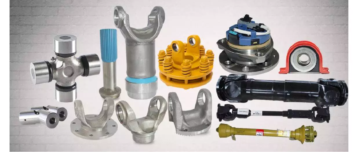
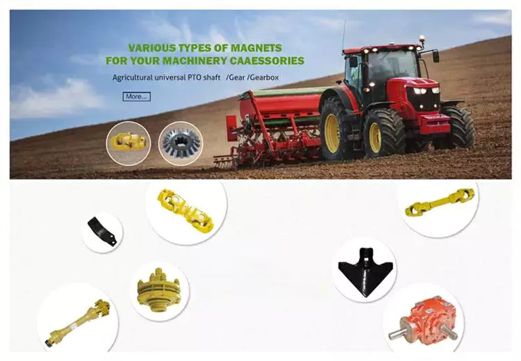
These gearboxes are widely used in rotary tillers, lawn mowers, harvesters, hole diggers, pesticide sprayers, irrigation machines, fertilizer spreaders, blenders and so on. The main products are:
--Straight bevel gearbox
--Spiral bevel gearbox
--Planetary reducer
--Worm gearbox
HangZhou CHINAMFG International Trading Co.,Ltd is a modern enterprise specilizing in the development, production, sales and services of PTO shaft. We adhere to the principle of "Precise Driveline, Advocate Green", using advanced technology and equipments to ensure all the technical standards of precise driveline. So that the transmission efficiency can be maxmized and every drop of resource of customers' can be saved. Meanwhile, we have a customer-centric service system, providing a full range of pre-sale, sale and after-sale service. Customer satisfaction is our forever pursuit.
We follow the principle of people first, trying our best to set up a pleasant surroundings and platform of performance for each employee, so everyone can be self-consciously active to join in "Precise Driveline, Adocate Green" to embody the self-worth, enterprise value and social value.
Newnuro's goal is: reducing customer's purchase budget, support customers to earn more market.
Newnuro always finds solution for customers.Customer satisfaction is our ultimate goal and forever pursuit.
| Application: | Machinery, Agricultural Machinery |
|---|---|
| Function: | Distribution Power, Change Drive Torque, Change Drive Direction, Speed Changing, Speed Reduction, Speed Increase |
| Layout: | Assembled |
| Hardness: | Hardened Tooth Surface |
| Installation: | Horizontal Type |
| Step: | Single-Step |
| Samples: |
US$ 50/Piece
1 Piece(Min.Order) | |
|---|
| Customization: |
Available
| Customized Request |
|---|

How do PTO shafts handle variations in length and connection methods?
PTO (Power Take-Off) shafts are designed to handle variations in length and connection methods to accommodate different equipment setups and ensure efficient power transfer. PTO shafts need to be adjustable in length to bridge the distance between the power source and the driven machinery. Additionally, they must provide versatile connection methods to connect to a wide range of equipment. Here's a detailed explanation of how PTO shafts handle variations in length and connection methods:
1. Telescoping Design: PTO shafts often feature a telescoping design, allowing them to be adjusted in length to suit different equipment configurations. The telescoping feature enables the shaft to extend or retract, accommodating varying distances between the power source (such as a tractor or engine) and the driven machinery. By adjusting the length of the PTO shaft, it can be properly aligned and connected to ensure optimal power transfer. Telescoping PTO shafts typically consist of multiple tubular sections that slide into one another, providing flexibility in length adjustment.
2. Splined Shafts: PTO shafts commonly employ splined shafts as the primary connection method between the power source and driven machinery. Splines are a series of ridges or grooves along the shaft that interlock with corresponding grooves in the mating component. The splined connection allows for torque transfer while maintaining alignment between the power source and driven machinery. Splined shafts can handle variations in length by extending or retracting the telescoping sections while still maintaining a solid connection between the power source and the driven equipment.
3. Adjustable Sliding Yokes: PTO shafts typically feature adjustable sliding yokes on one or both ends of the shaft. These yokes allow for angular adjustment, accommodating variations in the alignment between the power source and driven machinery. The sliding yokes can be moved along the splined shaft to achieve the desired angle and maintain proper alignment. This flexibility ensures that the PTO shaft can handle length variations while ensuring efficient power transfer without placing excessive strain on the universal joints or other components.
4. Universal Joints: Universal joints are integral components of PTO shafts that allow for angular misalignment between the power source and driven machinery. They consist of a cross-shaped yoke with bearings that transmit torque between connected shafts while accommodating misalignment. Universal joints provide flexibility in connecting PTO shafts to equipment that may not be perfectly aligned. As the PTO shaft length varies, the universal joints compensate for the changes in angle, allowing for smooth power transmission even when there are variations in length or misalignment between the power source and driven machinery.
5. Coupling Mechanisms: PTO shafts utilize various coupling mechanisms to securely connect to the power source and driven machinery. These mechanisms often involve a combination of splines, bolts, locking pins, or quick-release mechanisms. The coupling methods can vary depending on the specific equipment and industry requirements. The versatility of PTO shafts allows for the use of different coupling methods, ensuring a reliable and secure connection regardless of the length variation or equipment configuration.
6. Customization Options: PTO shafts can be customized to handle specific length variations and connection methods. Manufacturers offer options to select different lengths of telescoping sections to match the specific distance between the power source and driven machinery. Additionally, PTO shafts can be tailored to accommodate various connection methods through the selection of splined shaft sizes, yoke designs, and coupling mechanisms. This customization enables PTO shafts to meet the specific requirements of different equipment setups, ensuring optimal power transfer and compatibility.
7. Safety Considerations: When handling variations in length and connection methods, it is essential to consider safety. PTO shafts incorporate protective guards and shields to prevent accidental contact with rotating components. These safety measures must be appropriately adjusted and installed to provide adequate coverage and protection, regardless of the PTO shaft's length or connection configuration. Safety guidelines and regulations should be followed to ensure the proper installation, adjustment, and use of PTO shafts in order to prevent accidents or injuries.
By incorporating telescoping designs, splined shafts, adjustable sliding yokes, universal joints, and versatile coupling mechanisms, PTO shafts can handle variations in length and connection methods. The flexibility of PTO shafts allows them to adapt to different equipment setups, ensuring efficient power transfer while maintaining alignment and safety.

How do PTO shafts contribute to the efficiency of agricultural operations?
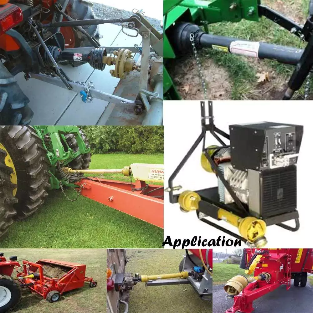
Power Take-Off (PTO) shafts play a crucial role in improving the efficiency of agricultural operations by providing a versatile and reliable power source for various farming equipment. PTO shafts allow agricultural machinery to access power from tractors or other prime movers, enabling the efficient transfer of energy to perform a wide range of tasks. Here's a detailed explanation of how PTO shafts contribute to the efficiency of agricultural operations:
1. Versatility: PTO shafts offer versatility by allowing the connection of different types of implements and machinery to tractors or other power sources. This versatility enables farmers to use a single power unit, such as a tractor, to operate multiple agricultural implements, including mowers, balers, tillers, seeders, sprayers, and more. The ability to quickly switch between various implements using a PTO shaft minimizes downtime and maximizes efficiency in agricultural operations.
2. Power Transfer: PTO shafts efficiently transfer power from the tractor's engine to the agricultural implements. The rotating power generated by the engine is transmitted through the PTO shaft to drive the machinery connected to it. This direct power transfer eliminates the need for separate engines or motors on each implement, reducing equipment costs and maintenance requirements. PTO shafts ensure a reliable power supply, allowing agricultural operations to be carried out efficiently and effectively.
3. Increased Productivity: By utilizing PTO shafts, agricultural operations can be performed more quickly and efficiently than manual or alternative power methods. PTO-driven machinery typically operates at higher speeds and with greater power compared to human-operated or manual tools. This increased productivity allows farmers to complete tasks such as tilling, seeding, harvesting, and material handling more efficiently, reducing labor requirements and increasing overall farm productivity.
4. Time Savings: PTO shafts contribute to time savings in agricultural operations. The ability to connect and disconnect implements quickly using standardized PTO shafts allows farmers to switch between tasks rapidly. This saves time during equipment setup, as well as when transitioning between different operations in the field. Time efficiency is particularly valuable during critical farming periods, such as planting or harvesting, where timely execution is essential for optimal crop yield and quality.
5. Reduced Manual Labor: PTO shafts minimize the need for manual labor in strenuous or repetitive tasks. By harnessing the power of tractors or other prime movers, farmers can mechanize various operations that would otherwise require significant physical effort. Agricultural implements driven by PTO shafts can perform tasks such as plowing, mowing, and baling with minimal human intervention, reducing labor costs and improving overall efficiency.
6. Precision and Consistency: PTO shafts contribute to precision and consistency in agricultural operations. The consistent power supply from the PTO ensures uniform operation and performance of the connected machinery. This helps in achieving consistent seed placement, even spreading of fertilizers or chemicals, and precise cutting or harvesting of crops. Precision and consistency lead to improved crop quality, enhanced yield, and reduced waste, ultimately contributing to the overall efficiency of agricultural operations.
7. Adaptability to Various Terrain: PTO-driven machinery is highly adaptable to various types of terrain encountered in agricultural operations. Tractors equipped with PTO shafts can traverse uneven or challenging terrain, allowing implements to operate effectively on slopes, rough fields, or hilly landscapes. This adaptability ensures that farmers can efficiently manage their land, regardless of topographical challenges, enhancing operational efficiency and productivity.
8. Integration with Automation and Technology: PTO shafts can be integrated with automation and technology advancements in modern agricultural practices. Automation systems, such as precision guidance and control, can be synchronized with PTO-driven machinery to optimize operations and minimize waste. Additionally, advancements in data collection and analysis allow farmers to monitor and optimize machine performance, fuel efficiency, and productivity, further enhancing the efficiency of agricultural operations.
By providing versatility, efficient power transfer, increased productivity, time savings, reduced manual labor, precision, adaptability to terrain, and integration with automation and technology, PTO shafts significantly contribute to enhancing the efficiency of agricultural operations. They enable farmers to perform a wide range of tasks with ease, ultimately improving productivity, reducing costs, and supporting sustainable farming practices.

Which industries commonly use PTO shafts for power transmission?
PTO shafts (Power Take-Off shafts) are widely used in various industries where power transmission is required to drive machinery and equipment. Their versatility, efficiency, and compatibility with different types of machinery make them valuable components in several sectors. Here's a detailed explanation of the industries that commonly use PTO shafts for power transmission:
1. Agriculture: The agricultural industry extensively relies on PTO shafts for power transmission. Tractors equipped with PTOs are commonly used to drive a wide range of agricultural implements and machinery. PTO-driven equipment includes mowers, balers, tillers, seeders, sprayers, grain augers, harvesters, and many more. PTO shafts allow for the efficient transfer of power from the tractor's engine to these implements, enabling various agricultural operations such as cutting, baling, tilling, planting, spraying, and harvesting. The agricultural sector heavily depends on PTO shafts to enhance productivity and streamline farming processes.
2. Construction and Earthmoving: In the construction and earthmoving industry, PTO shafts find applications in machinery used for excavation, grading, and material handling. PTO-driven equipment such as backhoes, loaders, excavators, trenchers, and stump grinders utilize PTO shafts to transfer power from the prime movers, typically hydraulic systems, to drive the necessary attachments. These attachments require the high torque and power provided by PTO shafts to perform tasks like digging, loading, trenching, and grinding. PTO shafts allow for versatile and efficient power transmission in construction and earthmoving operations.
3. Forestry: The forestry industry utilizes PTO shafts for power transmission in various logging and timber processing equipment. PTO-driven machinery such as wood chippers, sawmills, log splitters, and debarkers rely on PTO shafts to transfer power from tractors or dedicated power units to perform tasks like chipping, sawing, splitting, and debarking wood. PTO shafts provide the necessary power and torque to drive the cutting and processing mechanisms, enabling efficient and productive forestry operations.
4. Landscaping and Groundskeeping: PTO shafts play a crucial role in the landscaping and groundskeeping industry. Equipment like lawn mowers, rotary cutters, flail mowers, and aerators utilize PTO shafts to transfer power from tractors or dedicated power units to drive the cutting or grooming mechanisms. PTO shafts enable efficient power transmission, allowing operators to maintain lawns, parks, golf courses, and other outdoor spaces with precision and productivity.
5. Mining and Quarrying: PTO shafts have applications in the mining and quarrying industry, particularly in equipment used for material extraction, crushing, and screening. PTO-driven machinery such as crushers, screeners, and conveyors rely on PTO shafts to transfer power from engines or motors to drive the crushing and screening mechanisms, as well as the material handling systems. PTO shafts provide the necessary power and torque to process and transport bulk materials effectively in mining and quarrying operations.
6. Industrial Manufacturing: PTO shafts are utilized in various industrial manufacturing processes that require power transmission to drive specific machinery and equipment. Industries such as food processing, textile manufacturing, paper production, and chemical processing may use PTO-driven machinery for tasks like mixing, blending, cutting, extruding, and conveying. PTO shafts enable efficient power transfer to these machines, ensuring smooth and reliable operation in industrial manufacturing settings.
7. Utilities and Infrastructure Maintenance: PTO shafts find applications in utilities and infrastructure maintenance operations. Equipment like street sweepers, sewer cleaners, road maintenance machines, and drain augers utilize PTO shafts to transfer power from trucks or dedicated power units to perform tasks like sweeping, cleaning, and maintenance of roads, sewers, and other public infrastructure. PTO shafts enable efficient power transmission, ensuring effective and reliable operation of these utility and maintenance machines.
8. Others: PTO shafts are also used in several other industries and sectors where power transmission is required. This includes applications in the transportation industry for powering refrigeration units, fuel pumps, and hydraulic systems in trucks and trailers. PTO shafts also find applications in the marine industry for powering winches, pumps, and other equipment on boats and ships.
In summary, PTO shafts are commonly used in a wide range of industries for power transmission. These industries include agriculture, construction and earthmoving, forestry, landscaping and groundskeeping, mining and quarrying, industrial manufacturing, utilities and infrastructure maintenance, transportation, and marine sectors. PTO shafts play a critical rolein enhancing productivity, enabling efficient operation of machinery, and facilitating various tasks in these industries.

editor by CX 2023-09-15
China supplier Tractor Rotary Mowers Bevel Cultivator Tillers Right Angle Pto Shaft Reducer Gearbox for Farm and Agricultural Machinery
Product Description
Tractor Rotary Mowers Bevel Fertilizer Spreader Tillers Right Angle Pto Shaft Reducer Gearbox for Farm and Agricultural Machinery
Established in Nov.2002,HangZhou CHINAMFG is a professional manufacturer and supplier in supplying spare parts and accessories for agricultural machinery. In addition to the 3000 standards parts, we also offer our customers tailor-made articles or assemblies that are for special application.
HangZhou CHINAMFG focused on the development and production of gearboxes with a professional team and continue to learn advanced technology; the use of first-class equipment; high quality supply chain system, relying on these, the gearboxes get high reputation among customers at home and abroad.
These gearboxes are widely used in rotary tillers, lawn mowers, harvesters, hole diggers, pesticide sprayers, irrigation machines, fertilizer spreaders, blenders and so on. The main products are:
--Straight bevel gearbox
--Spiral bevel gearbox
--Planetary reducer
--Worm gearbox
HangZhou CHINAMFG International Trading Co.,Ltd is a modern enterprise specilizing in the development, production, sales and services of PTO shaft. We adhere to the principle of "Precise Driveline, Advocate Green", using advanced technology and equipments to ensure all the technical standards of precise driveline. So that the transmission efficiency can be maxmized and every drop of resource of customers' can be saved. Meanwhile, we have a customer-centric service system, providing a full range of pre-sale, sale and after-sale service. Customer satisfaction is our forever pursuit.
We follow the principle of people first, trying our best to set up a pleasant surroundings and platform of performance for each employee, so everyone can be self-consciously active to join in "Precise Driveline, Adocate Green" to embody the self-worth, enterprise value and social value.
Newnuro's goal is: reducing customer's purchase budget, support customers to earn more market.
Newnuro always finds solution for customers.Customer satisfaction is our ultimate goal and forever pursuit.
| Application: | Machinery, Agricultural Machinery |
|---|---|
| Function: | Distribution Power, Change Drive Torque, Change Drive Direction, Speed Changing, Speed Reduction, Speed Increase |
| Layout: | Assembled |
| Hardness: | Hardened Tooth Surface |
| Installation: | Horizontal Type |
| Step: | Single-Step |
| Samples: |
US$ 50/Piece
1 Piece(Min.Order) | |
|---|
| Customization: |
Available
| Customized Request |
|---|
Can tractor PTO shafts be customized for specific implement or machinery requirements?
Yes, tractor power take-off (PTO) shafts can be customized to meet specific implement or machinery requirements. Customization allows for the optimal integration of PTO shafts with different agricultural implements and machinery. Here's a detailed explanation:
1. Length and Size: PTO shafts can be customized in terms of length and size to suit specific requirements. Different implements or machinery may have varying distance requirements between the tractor's PTO output and the input shaft of the implement. Customizing the length ensures proper alignment and a secure connection. Additionally, the size of the PTO shaft, such as the diameter, can be adjusted to match the power and torque requirements of the implement.
2. Attachment Methods: PTO shafts can be customized to accommodate different attachment methods required by specific implements. The attachment method refers to how the PTO shaft connects to the implement's input shaft. Common attachment methods include a shear pin, a quick-release collar, or a splined connection. Customization allows manufacturers to provide the appropriate attachment method based on the implement's design and requirements.
3. Shaft Configurations: PTO shafts can have different configurations to suit specific implement or machinery designs. For example, some implements may require a straight shaft, while others may need a telescopic or sliding shaft to accommodate variable distance requirements during operation. Customizing the shaft configuration ensures a proper fit and allows for smooth operation without compromising safety.
4. Protection and Shielding: Customization of PTO shafts can include additional protection and shielding features. Agricultural tasks often involve debris and potential hazards that can damage the PTO shaft. Manufacturers can customize the shaft by adding protective guards, such as metal or polymer shields, to prevent entanglement or contact with external objects. This customization enhances safety and prolongs the lifespan of the PTO shaft.
5. Specific Industry Standards: Some industries or applications may have specific standards or regulations for PTO shafts. Manufacturers can customize PTO shafts to meet these specific industry requirements, ensuring compliance with safety standards and compatibility with machinery used in those industries.
It's important to note that the customization of PTO shafts is typically carried out by the manufacturers or specialized suppliers. They have the expertise and knowledge to design and manufacture customized PTO shafts that meet the required specifications and standards.
In summary, tractor PTO shafts can be customized to accommodate specific implement or machinery requirements. Customization options include adjusting the length and size, adapting attachment methods, configuring the shaft design, adding protection and shielding, and meeting specific industry standards. Customized PTO shafts ensure optimal integration and performance, enhancing the overall efficiency and safety of agricultural operations.
How do tractor PTO shafts accommodate variations in length and attachment methods?
Tractor PTO shafts are designed to accommodate variations in length and attachment methods to ensure compatibility with different agricultural implements. Here's a detailed explanation:
1. Telescoping Design: Many tractor PTO shafts feature a telescoping design, allowing them to be adjusted to different lengths. Telescoping PTO shafts have multiple sections that can slide in and out, enabling the shaft to be extended or retracted as needed. This feature helps accommodate variations in the distance between the tractor's PTO output shaft and the implement's input shaft.
2. Adjustable Locking Mechanisms: PTO shafts typically incorporate adjustable locking mechanisms to secure the desired length. These mechanisms may involve pins, clamps, or other locking devices that allow the operator to fix the telescoping sections at the desired position. By adjusting the locking mechanism, the PTO shaft can be set to the appropriate length based on the specific requirements of the equipment.
3. Compatible Attachment Methods: Tractor PTO shafts are designed to accommodate different attachment methods used by agricultural implements. The most common attachment method is the use of a splined connection, where the PTO shaft slides onto the implement's input shaft and is secured with a shear pin or a locking collar. The splined connection allows for a secure and reliable attachment, ensuring efficient power transfer.
4. Adapters and Couplings: In cases where the attachment methods between the tractor and the implement do not match, adapters or couplings can be used. These devices provide compatibility between different attachment methods or spline sizes. Adapters and couplings may feature different types of connections on each end to bridge the gap between the tractor's PTO shaft and the implement's input shaft, allowing for a proper and secure attachment.
5. PTO Shielding: PTO shafts also accommodate variations in PTO shielding requirements. Depending on the implement and local safety regulations, different types of shielding may be necessary. Tractor PTO shafts can be designed with detachable shielding options or offer flexibility in the positioning of safety shields to ensure compliance with safety standards.
By incorporating telescoping designs, adjustable locking mechanisms, compatible attachment methods, adapters and couplings, and considerations for PTO shielding, tractor PTO shafts can accommodate variations in length and attachment methods. These features allow for flexibility and ensure the proper fit and safe operation of the PTO shaft with various agricultural implements.
Can You Explain the Functions and Significance of a Tractor PTO Shaft?
A tractor power take-off (PTO) shaft is a critical component in agricultural machinery that serves several functions and holds significant importance in farm operations. It enables the transfer of power from the tractor's engine to various implements, allowing them to perform specific tasks. Here's a detailed explanation of the functions and significance of a tractor PTO shaft:
1. Power Transfer:
The primary function of a tractor PTO shaft is to transfer power from the tractor's engine to attached implements. The PTO shaft connects directly to the power source of the tractor, utilizing the engine's rotational energy and converting it into the desired speed and torque required by the implement. This power transfer eliminates the need for separate engines on each implement, making farm operations more efficient and cost-effective.
2. Versatility and Flexibility:
A tractor PTO shaft enhances the versatility and flexibility of farm machinery. It allows farmers to quickly attach and detach implements, accommodating various tasks and seasonal requirements. With a detachable and interchangeable PTO shaft, farmers can efficiently utilize the power of the tractor across different implements, maximizing productivity and reducing downtime. This flexibility enables farmers to adapt to changing farming needs and efficiently manage their operations.
3. Compatibility:
Tractor PTO shafts are designed to be compatible with a wide range of implements used in agriculture. The PTO shaft's standardized connection interface ensures that implements from different manufacturers can be easily attached to the tractor. This compatibility allows farmers to utilize specialized equipment for specific tasks such as mowing, tilling, planting, harvesting, or baling. The PTO shaft serves as a critical link that enables seamless integration and operation of various implements.
4. Speed and Power Control:
Tractor PTO shafts offer speed and power control, allowing farmers to adjust the rotational speed and torque delivered to the implement. Tractors typically provide multiple PTO speed options, such as 540 or 1,000 revolutions per minute (RPM). By selecting the appropriate PTO speed, farmers can optimize the performance and efficiency of the attached equipment, ensuring proper operation and achieving desired outcomes. Speed and power control contribute to effective and precise use of farm implements.
5. Enhanced Efficiency and Productivity:
The functions of a tractor PTO shaft contribute to enhanced efficiency and productivity in farm operations. By enabling the use of various implements with a single tractor, the PTO shaft reduces the need for multiple machines and manual labor. Farmers can efficiently perform a wide range of tasks such as plowing, seeding, cultivating, and harvesting using different attachments connected to the PTO shaft. This streamlined approach saves time, reduces costs, and improves overall productivity.
6. Safety Considerations:
When using a tractor PTO shaft, safety is of utmost importance. PTO shafts are equipped with protective guards or shields to prevent accidental contact with the rotating shaft. These guards protect operators and bystanders from potential hazards and entanglement. It is crucial to ensure that the PTO shaft and its safety features are properly maintained and used according to recommended guidelines to minimize the risk of accidents or injuries.
7. Integral Component of Farm Machinery:
A tractor PTO shaft is an integral component of modern farm machinery. It plays a vital role in the overall effectiveness of agricultural operations by enabling the use of a wide range of implements, facilitating power transfer, and improving efficiency. The PTO shaft's significance lies in its ability to connect the tractor's power source with implements, providing the necessary power and flexibility to accomplish various farming tasks.
In summary, a tractor PTO shaft functions as a power transfer mechanism, providing versatility, compatibility, speed and power control, and enhancing efficiency and productivity in farm operations. It is an essential component that simplifies and streamlines agricultural tasks, making modern farming practices more efficient and effective.
editor by CX 2023-09-14
China manufacturer Telake Compact Professional Agricultural Machinery Garden Tool Farming Tractor with Hot selling
Product Description
Product Description:TK160-180HP series tractor is designed for works on middle-scale farms and auxiliary works on large farm
land. It equips with Chinese famous supercharged engine, 6 cylinders, produces more power and less
fuel consumption, making the work more energy-efficient.
With dynamic and fashionable appearance, flat floor, side console and suspension pedal, HANWO patent
luxury cab, with A/C or heater, provide you a safe, quite and comfortable driving condition.
Standard with enhanced chassis and 16F+8R shuttle shift gearbox, optional creeper type gear shift, to
meet the requirements on more rational speeds;
Equipped with strong pressure device lifter to ensure the best rotary tillage and plowing effect. Force
control, position control or floating control is optional for different conditions.
We use category II type three-point hitch, up to international standard; enhanced lifting arms and
quick-change connectors improve the general strength while matching various implements.
Optional Herringbone tires, radial tires or other type of tires to meet your needs of working conditions;
Main Technical Specifications:
| Model | TK1504 | TK1604 | TK1804 | ||
| Type | 4×4 | 4×4 | 4×4 | ||
|
Dimensions of Tractor (mm) |
L×W×H | 5060×2300×3100 | 5280×2340×3100 | 5280×2340×3100 | |
| Tread | Front Wheel | 1612, 1712, 1952,2072 | 1612, 1712, 1952,2072 | 1612, 1712, 1952,2072 | |
| Rear Wheel | 1620~2420(usual 1800) | 1700~2300(usual 1800) | 1700~2300(usual 1800) | ||
| Wheel Base | 2510 | 2657 | 2657 | ||
| Min. Ground Base | 395 (the bottom of front axle ) | 450 (the bottom of traction plate ) | |||
| Min. Usage Mass(kg) | 5300 | 5500 | 5500 | ||
|
Engine |
Model | Weichai WP6G150E330A | Weichai WP6G160E330 | Weichai WP6G180E330 | |
| Type | Vertical, water cooled, 4-stroke, turbocharged, intercooled type | ||||
| Rated Power(kw) | 110.3 | 118 | 132.5 | ||
| Rated Rev.(r/min) | 2200 | 2200 | 2200 | ||
| Fuel | Diesel Oil | ||||
| Tire | Front Wheel | Standard 14.9-26 | |||
| Rear Wheel | Standard 18.4-38 | ||||
| Clutch | Dry-friction, Dual stage, Hydraulic power assisted | ||||
| Steering | Hydraulic type | ||||
| Transmission Box | 16F+8R Collar Shift | ||||
| Suspension Type | Post Positioned Three-point Suspension Catalogue III | ||||
| PTO | Type and Rev.(r/min) | Post-position, independent type 760/850 | |||
| Spline Size | φ38 Rectangle Spline with 8 teeth | ||||
Technology & Innovation:
WeiFang Telake has established a professional R & D team, realized the self-control ability of core components by integrating the industry's
advantageous resources, built a stable quality control system.
Invested tens millions to introduce intelligent mechanization total production line, automatic chassis production line, gearbox processing line and welding
robots, processing centers and other advanced production lines and equipment, to achieve an annual production capacity of 30,000 tractors.
/////////////////////////////////////////////////////////////////////////////////////////////////////////////////////////////////////////////////////////////////////
Packaging & Delivery:
-Delivery time:20- 30 days.
/////////////////////////////////////////////////////////////////////////////////////////////////////////////////////////////////////////////////////////////////////
Certifications:
Common problems
(1) Are you a manufacturing factory or a trading company?
We are a factory with 20 years of professional production experience in the field of 25hp-240hp tractors, located in HangZhou City, ZheJiang Province, China. Our factory has passed ISO9001, CCC, CE, SGS and BV certification. We also have a quality control department to purchase products for customers. This is why the price of our tractors is so reasonable.
(2) Can we print the logo or company name on your product or packaging?
of course. Your logo can be printed on your product by embossing, self-adhesive or silk-screen printing.
(3) About the price
The price is negotiable. It can be changed according to the options or packaging of the tractor.
(4) Regarding payment or other issues
We accept LC, TT, if you have other questions, please email me or chat with me directly.
Contact
Welcome to our factory
Adhere to the business tenet of "Integrity-based, Quality First", and wholeheartedly provide you with the best products and wholehearted service. We actively cooperate with research institutions and multinational companies to achieve continuous innovation. HangZhou Telake Agricultural Equipment CO.,LTD welcomes domestic and foreign customers to visit and guide!
HangZhou Telake Agricultural Equipment CO.,LTD
Adress: East of Xihu (West Lake) Dis. Road,South of Cailin Road,Xihu (West Lake) Dis. Economic District,HangZhou,ZheJiang ,China
Calculate the ideal mechanical advantage of pulleys
The basic equations for pulleys can be found in this article. It will also cover the different types of pulleys, the ideal mechanical advantages of pulleys, and some common uses of pulley systems. Read on to learn more! After all, a pulley is a simple mechanical device that changes the direction of a force. Learn more about pulleys and their common uses in engineering.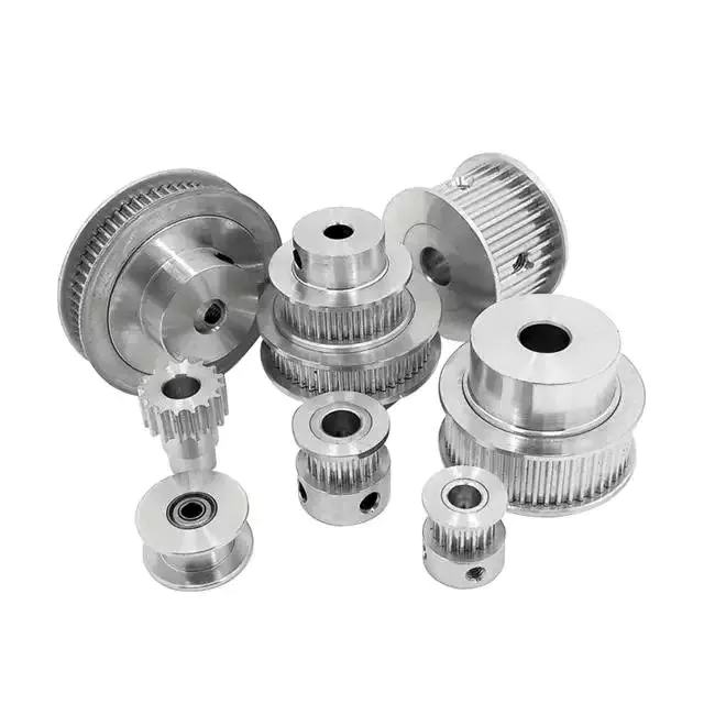
pulley basic equation
Pulleys work the same way as gravity, so they should withstand similar forces. Newton's laws of motion can be used to calculate the forces in a pulley system. The second law of motion applies to forces and accelerations. Similar to this is Newton's third law, which states that the directions of forces are equal and opposite. The fourth law dictates the direction of force. The Fifth Law states that tension is in equilibrium with gravity.
A pulley is a simple mechanism that transmits force by changing direction. They are generally considered to have negligible mass and friction, but this is only an approximation. Pulleys have different uses, from sailboats to farms and large construction cranes. In fact, they are the most versatile mechanisms in any system. Some of their most common applications and equations are listed below.
For example, consider 2 masses m. Those of mass m will be connected by pulleys. The static friction coefficient of the left stop is ms1, and the static friction coefficient of the right stop is ms2. A no-slip equation will contain multiple inequalities. If the 2 blocks are considered to be connected by a pulley, the coefficient of kinetic friction is mk. In other words, the weight of each block carries the same mass, but in the opposite direction.
Types of pulleys
A pulley is a device used to pull and push objects. Pulley systems are ropes, cables, belts or chains. The "drive pulley" is attached to the shaft and moves the driven pulley. They are available in a variety of sizes, and the larger they are, the higher the speed of power transmission. Alternatively, use small pulleys for smaller applications.
Two-wheel pulleys have 2 mechanical advantages. The greater the mechanical advantage, the less force is required to move the object. More wheels lift more weight, but smaller pulleys require less force. In a two-wheel pulley system, the rope is wound around 2 axles and a fixed surface. As you pull on the rope, the shafts above slowly come together.
Compound pulleys have 2 or more rope segments that are pulled up on the load. The mechanical advantage of compound pulleys depends on the number of rope segments and how they are arranged. This type of pulley can increase the force by changing the direction of the rope segment. There are 2 main types of pulleys. Composite pulleys are most commonly used in construction. The ideal mechanical advantage of pulleys is 2 or more.
Construction pulleys are a basic type. They are usually attached to wheel rails and can be lifted to great heights. Combinations of axes are also common. Construction pulleys can be raised to great heights to access materials or equipment. When used in construction, these pulleys are usually made of heavy materials such as wood or metal. They are secured with ropes or chains.
The ideal mechanical advantage of pulleys
The pulley system is a highly complex system with high mechanical advantages. Use a single pulley system to reduce the force required to lift an object by cutting it in half. The mechanical advantage increases as you add more pulleys, such as 6 or seven. To calculate the mechanical advantage of a pulley system, you need to count the number of rope segments between the pulleys. If the free end of the rope is facing down, don't count it. If it's facing up, count. Once you have your number, add it up.
The required mechanical advantage of a pulley is the number of rope segments it has to pull the load. The more rope segments, the lower the force. Therefore, the more rope segments the pulley has, the lower the force. If the rope segments are four, then the ideal mechanical advantage is four. In this case, the composite pulley quadrupled the load force.
The ideal mechanical advantage of a pulley system is the sum of the mechanical force and the force required to lift the load at its output. Typically, a single pulley system uses 2 ropes, and the mechanical force required to lift the load is multiplied by the 2 ropes. For a multi-pulley system, the number of ropes will vary, but the total energy requirement will remain the same. The friction between the rope and pulley increases the force and energy required to lift the load, so the mechanical advantage diminishes over time.
Common uses of pulley systems
A pulley system is a simple mechanical device typically used to lift heavy objects. It consists of a rotating wheel attached to a fixed shaft and a rope attached to it. When the wheel moves, the force applied by the operator is multiplied by the speed of the pulley, and the force is multiplied by the weight of the object being lifted. Common uses for pulley systems include pulling, lifting, and moving heavy objects.
The oil and petroleum industries use pulley systems in a variety of applications. Most commonly, pulleys are used in drilling operations and they are installed on top of the rig to guide the cable. The cable itself is attached to 2 pulleys suspended in the derrick, where they provide mechanical energy to the cable. Using a pulley system in this application provides the force needed to move the cable safely and smoothly.
The main advantage of the pulley system is that it minimizes the force required to lift an object. The force used to lift the object is multiplied by the desired mechanical advantage. The more rope segments, the lower the force required. On the other hand, a compound pulley system can have many segments. Therefore, a compound pulley system can increase the force a worker can exert on an object.
Safety Precautions to Take When Working on Pulley Systems
There are many safety precautions that should be observed when working on a pulley system. The first is to wear proper protective gear. This includes hard hats that protect you from falling objects. Also, gloves may be required. You should limit the amount of movement in the penalty area, and you should also keep the area free of unnecessary people and objects. Also, remember to wear a hard hat when working on the pulley system.
Another important safety precaution when working on a pulley system is to check the Safe Working Load (SWL) of the pulley before attaching anything. This will help you understand the maximum weight the pulley can hold. Also, consider the angle and height of the pulley system. Always use safety anchors and always remember to wear a hat when working on a pulley system.
Safe use of chain hoists requires training and experience. It is important to read the manufacturer's manual and follow all safety precautions. If you're not sure, you can actually inspect the hoist and look for signs of damage or tampering. Look for certifications for sprocket sets and other lifting accessories. Look for the Safe Working Load (SWL) marking on the chain hoist.
Example of a pulley system
Pulley systems are often used to lift items. It allows you to reduce the effort to lift and move the load by applying force in 1 direction. Pulley systems can be built and modeled to fit any type of project. This resource focuses on pulley systems and is designed to support the new GCSEs in Engineering, Design and Technology. There are also many examples of pulley systems suitable for various applications.
In the study, participants who read easy text took longer to manipulate the pulley system than those who read challenging text. In general, this suggests that participants with prior scientific experience used their cognitive abilities more effectively. Additionally, students who read simple texts spent less time planning the pulley system and more time on other tasks. However, the study did show that the time required to plan the pulley system was similar between the 2 groups.
In everyday life, pulley systems are used to lift various objects. Flagpoles are 1 of many pulley systems used to raise and lower flagpoles. They can also be used to raise and lower garage doors. Likewise, rock climbers use pulleys to help them ascend and descend. The pulley system can also be used to extend the ladder.


China Good quality Agricultural Machinery Tractor 3 Point Hitch Rotary Disc Mower for Sale with Hot selling
Product Description
PRODUCT DESCRIPTION
This rotary disc mower is attached to the tractor rear suspension frame, and the power output shaft is used for operation. The machine has 4-8 high-speed rotating Cutterheads. Each cutterhead is equipped with 2 blades. It can work at high speed up to 1-2 hectares per hour with high productivity.
The rotation of cutter-heads of this mower is driven by gear instead of traditional belt drive, which makes the work stable, the failure rate low and the maintenance cost low.
Because of spring suspension and belt rotation, the knife beam is low, easy to rise and fall, it can cut close to the ground, with low cutting stubble, and has a good imitation ability to the ground.
When the cutting blade encounters a big obstacle, it can be knocked back to avoid damage to the blade. The mower relies on the rotating force of the turntable to concentrate the grass in the middle position for easy collection.
Advantage:
1) The disc mower cuts through heavy, high crops without wraping or plugging, as well as for light thin grass.
It is suitable for native grass,alfalfa,corn and other stalks.
2) Rotary disc mower can be raised quickly for turning or transport without adjusting the 3 point hitch.
3) The disc mower siutable for wide range terrains and contours,even uneven and rocky ground.
RODUCT SPECIFICATION
| Model | Unit | 9GRM-1300 | 9GRM-1700 | 9GRM-2100 | 9GRM-2500 |
| Working width | mm | 1250 | 1650 | 2050 | 2360 |
| Overall dimensions (L*W*H) | mm | 2080*1180*780 | 2533*1180*780 | 2950*1280*780 | 3270*1280*780 |
| Quantity of discs | Pc | 3 | 4 | 5 | 6 |
| Quantity of blades | Pc | 6 | 8 | 10 | 12 |
| Working speed | Km/h | 4-10 | |||
| PTO rotation speed | r/min | 540-720 | |||
| Matched Tractor power | hp | 20-50 | 35-80 | 45-85 | 50-110 |
| Machine Weight | kg | 280 | 370 | 400 | 450 |
| Linkage type | Tractor 3 point mounted | ||||
RODUCT SHOW
RELATED PRODUCTS
FAQ
| Q1: Are you a factory or trading company? |
|---|
|
We are a factory with self-supported import and export right with more than 10 years of manufacturing experience. |
| Q2: How can I trust on your company? |
|
We are a fully registered manufacture and exporting company by China Export Registration Authorities. Moreover, our products have been exporting to a number of countries including Switzerland, Russia, Spain, Netherlands, Australia, Peru, Thailand, Pakistan, Indonesia, Tanzania, Nigeria, South Africa, Sudan, Congo etc. The good faith, punctual, strict quality control and reasonable price, throughout is the pledge we to each customer. |
| Q3: Where is your factory located? How can I visit there? |
|
Our factory is located in HangZhou City, ZheJiang Province, China. About 1 hour away from HangZhou Airport. All our clients are warmly welcomed to visit us! |
| Q4: How can I place an order from your website? |
|
It is very easy.Once you find the implement you need on our website and place an inquiry against it, or, get to the inquiry section and leave us a message there with name, country and phone number, we will get in touch with you at the earliest. You can also e-mail us directly or join us on live chat for instantaneous answers. |
| Q5: How can I make the payment? |
|
Payment is made via Telegraphic Transfer (T/T) through the bank against the proforma invoice. |
| Q6: What's the Payment terms? |
|
FOB, the price of the implement without sea shipment costs. |
| Q7: At which port do you usually ship the good? |
|
We usually ship goods via HangZhou, ZheJiang , HangZhou, ZheJiang port of China. |
| Q8. How about the Warranty ? |
|
15 months warranty from the time of the goods arrive at destination. |
COMPANY INTRODUCTION
1) More than 10 years of manufacturing expenrience in the field of general machineries.
2) Professional engineers and test equipments to ensure the quality of each machine.
3) Factory direct selling at competitive prices.
4) Good parts assembled, strictly quality control system.5) Compact structure, beautiful appearance,small volume, light weight, fuel consumption is low, the power is great
6) Start convenient easy, low noise,little vibration,smooth operation,reliable performance.
7) OEM welcome, small order acceptable, ample supply and prompt delivery.
8) YCHS MACHIERY is a manufacturer, have own factories.
9) The biggest advantages: Top quality, Competitive price & Good after-sales service
"Top quality, Competitive price, Good after-sales service" is our big advantages.
Welcome to contact us at any time, sincerely hope we could have cooperation with you .
Have a nice day.
How to Design a Forging Spur Gear
Before you start designing your own spur gear, you need to understand its main components. Among them are Forging, Keyway, Spline, Set screw and other types. Understanding the differences between these types of spur gears is essential for making an informed decision. To learn more, keep reading. Also, don't hesitate to contact me for assistance! Listed below are some helpful tips and tricks to design a spur gear. Hopefully, they will help you design the spur gear of your dreams.
Forging spur gears
Forging spur gears is 1 of the most important processes of automotive transmission components. The manufacturing process is complex and involves several steps, such as blank spheroidizing, hot forging, annealing, phosphating, and saponification. The material used for spur gears is typically 20CrMnTi. The process is completed by applying a continuous through extrusion forming method with dies designed for the sizing band length L and Splitting angle thickness T.
The process of forging spur gears can also use polyacetal (POM), a strong plastic commonly used for the manufacture of gears. This material is easy to mold and shape, and after hardening, it is extremely stiff and abrasion resistant. A number of metals and alloys are used for spur gears, including forged steel, stainless steel, and aluminum. Listed below are the different types of materials used in gear manufacturing and their advantages and disadvantages.
A spur gear's tooth size is measured in modules, or m. Each number represents the number of teeth in the gear. As the number of teeth increases, so does its size. In general, the higher the number of teeth, the larger the module is. A high module gear has a large pressure angle. It's also important to remember that spur gears must have the same module as the gears they are used to drive.
Set screw spur gears
A modern industry cannot function without set screw spur gears. These gears are highly efficient and are widely used in a variety of applications. Their design involves the calculation of speed and torque, which are both critical factors. The MEP model, for instance, considers the changing rigidity of a tooth pair along its path. The results are used to determine the type of spur gear required. Listed below are some tips for choosing a spur gear:
Type A. This type of gear does not have a hub. The gear itself is flat with a small hole in the middle. Set screw gears are most commonly used for lightweight applications without loads. The metal thickness can range from 0.25 mm to 3 mm. Set screw gears are also used for large machines that need to be strong and durable. This article provides an introduction to the different types of spur gears and how they differ from 1 another.
Pin Hub. Pin hub spur gears use a set screw to secure the pin. These gears are often connected to a shaft by dowel, spring, or roll pins. The pin is drilled to the precise diameter to fit inside the gear, so that it does not come loose. Pin hub spur gears have high tolerances, as the hole is not large enough to completely grip the shaft. This type of gear is generally the most expensive of the three.
Keyway spur gears
In today's modern industry, spur gear transmissions are widely used to transfer power. These types of transmissions provide excellent efficiency but can be susceptible to power losses. These losses must be estimated during the design process. A key component of this analysis is the calculation of the contact area (2b) of the gear pair. However, this value is not necessarily applicable to every spur gear. Here are some examples of how to calculate this area. (See Figure 2)
Spur gears are characterized by having teeth parallel to the shafts and axis, and a pitch line velocity of up to 25 m/s is considered high. In addition, they are more efficient than helical gears of the same size. Unlike helical gears, spur gears are generally considered positive gears. They are often used for applications in which noise control is not an issue. The symmetry of the spur gear makes them especially suitable for applications where a constant speed is required.
Besides using a helical spur gear for the transmission, the gear can also have a standard tooth shape. Unlike helical gears, spur gears with an involute tooth form have thick roots, which prevents wear from the teeth. These gears are easily made with conventional production tools. The involute shape is an ideal choice for small-scale production and is 1 of the most popular types of spur gears.
Spline spur gears
When considering the types of spur gears that are used, it's important to note the differences between the two. A spur gear, also called an involute gear, generates torque and regulates speed. It's most common in car engines, but is also used in everyday appliances. However, 1 of the most significant drawbacks of spur gears is their noise. Because spur gears mesh only 1 tooth at a time, they create a high amount of stress and noise, making them unsuitable for everyday use.
The contact stress distribution chart represents the flank area of each gear tooth and the distance in both the axial and profile direction. A high contact area is located toward the center of the gear, which is caused by the micro-geometry of the gear. A positive l value indicates that there is no misalignment of the spline teeth on the interface with the helix hand. The opposite is true for negative l values.
Using an upper bound technique, Abdul and Dean studied the forging of spur gear forms. They assumed that the tooth profile would be a straight line. They also examined the non-dimensional forging pressure of a spline. Spline spur gears are commonly used in motors, gearboxes, and drills. The strength of spur gears and splines is primarily dependent on their radii and tooth diameter.
SUS303 and SUS304 stainless steel spur gears
Stainless steel spur gears are manufactured using different techniques, which depend on the material and the application. The most common process used in manufacturing them is cutting. Other processes involve rolling, casting, and forging. In addition, plastic spur gears are produced by injection molding, depending on the quantity of production required. SUS303 and SUS304 stainless steel spur gears can be made using a variety of materials, including structural carbon steel S45C, gray cast iron FC200, nonferrous metal C3604, engineering plastic MC901, and stainless steel.
The differences between 304 and 303 stainless steel spur gears lie in their composition. The 2 types of stainless steel share a common design, but have varying chemical compositions. China and Japan use the letters SUS304 and SUS303, which refer to their varying degrees of composition. As with most types of stainless steel, the 2 different grades are made to be used in industrial applications, such as planetary gears and spur gears.
Stainless steel spur gears
There are several things to look for in a stainless steel spur gear, including the diametral pitch, the number of teeth per unit diameter, and the angular velocity of the teeth. All of these aspects are critical to the performance of a spur gear, and the proper dimensional measurements are essential to the design and functionality of a spur gear. Those in the industry should be familiar with the terms used to describe spur gear parts, both to ensure clarity in production and in purchase orders.
A spur gear is a type of precision cylindrical gear with parallel teeth arranged in a rim. It is used in various applications, such as outboard motors, winches, construction equipment, lawn and garden equipment, turbine drives, pumps, centrifuges, and a variety of other machines. A spur gear is typically made from stainless steel and has a high level of durability. It is the most commonly used type of gear.
Stainless steel spur gears can come in many different shapes and sizes. Stainless steel spur gears are generally made of SUS304 or SUS303 stainless steel, which are used for their higher machinability. These gears are then heat-treated with nitriding or tooth surface induction. Unlike conventional gears, which need tooth grinding after heat-treating, stainless steel spur gears have a low wear rate and high machinability.
China high quality China CZPT Agricultural Machinery 60HP Tractor near me shop
Product Description
LUTONG LT604B Tractor
Products Features
LUTONG 60HP 4WD agricultural farm tractor garden tractor LT604
1.Famous brand diesel engine
2.Increase 30% efficience,Save 25% fuel
3.4 wheel drive, Shuttle shift 12F+12R, High Ground clearance.
4.Stable performance in Mountain Area with low maintenance rate.
5.Rear 3 point hitch, can equipped different farm implements easily.
Specifications
|
Model |
LT604 |
||||||||||||||||||||||||||||||||||||||||||||||||||||||||||||||||||||||||||||||||||||||||||||||||||||||||||||||||||||||||||||||||||||||||||||||||||||||||||||||||||||||||||||||||||||||||||||||||||||||||||||||||||||||||||||||||||||||||||||||||||||||||||||||||||||||||||||||||||||||||||||||||||||||||||||||||||||||||||||||||||||||||||||||||||||||||||||||||||||||||||||||||||||||||||||||||||||||||||||||||||||||||||||||||||||||||||||||||||||||||||||||||||||||||||||||||||||||||||||||||||||||||||||||||||||||||||||||||||||||||||||||||||||||||||||||||||||||||||||||||||||||||||||||||||||||||||||||||||||||||||||||||||||||||||||||||||||||||||||||||||||||||||||||||||||||||||||||||||||||||||||||||||||||||||||||||||||
|
Type |
4×4 |
||||||||||||||||||||||||||||||||||||||||||||||||||||||||||||||||||||||||||||||||||||||||||||||||||||||||||||||||||||||||||||||||||||||||||||||||||||||||||||||||||||||||||||||||||||||||||||||||||||||||||||||||||||||||||||||||||||||||||||||||||||||||||||||||||||||||||||||||||||||||||||||||||||||||||||||||||||||||||||||||||||||||||||||||||||||||||||||||||||||||||||||||||||||||||||||||||||||||||||||||||||||||||||||||||||||||||||||||||||||||||||||||||||||||||||||||||||||||||||||||||||||||||||||||||||||||||||||||||||||||||||||||||||||||||||||||||||||||||||||||||||||||||||||||||||||||||||||||||||||||||||||||||||||||||||||||||||||||||||||||||||||||||||||||||||||||||||||||||||||||||||||||||||||||||||||||||||
|
Dimensions (mm) |
Length (with front counterweight) |
4571 |
|||||||||||||||||||||||||||||||||||||||||||||||||||||||||||||||||||||||||||||||||||||||||||||||||||||||||||||||||||||||||||||||||||||||||||||||||||||||||||||||||||||||||||||||||||||||||||||||||||||||||||||||||||||||||||||||||||||||||||||||||||||||||||||||||||||||||||||||||||||||||||||||||||||||||||||||||||||||||||||||||||||||||||||||||||||||||||||||||||||||||||||||||||||||||||||||||||||||||||||||||||||||||||||||||||||||||||||||||||||||||||||||||||||||||||||||||||||||||||||||||||||||||||||||||||||||||||||||||||||||||||||||||||||||||||||||||||||||||||||||||||||||||||||||||||||||||||||||||||||||||||||||||||||||||||||||||||||||||||||||||||||||||||||||||||||||||||||||||||||||||||||||||||||||||||||||||||
|
Wide |
1890 |
||||||||||||||||||||||||||||||||||||||||||||||||||||||||||||||||||||||||||||||||||||||||||||||||||||||||||||||||||||||||||||||||||||||||||||||||||||||||||||||||||||||||||||||||||||||||||||||||||||||||||||||||||||||||||||||||||||||||||||||||||||||||||||||||||||||||||||||||||||||||||||||||||||||||||||||||||||||||||||||||||||||||||||||||||||||||||||||||||||||||||||||||||||||||||||||||||||||||||||||||||||||||||||||||||||||||||||||||||||||||||||||||||||||||||||||||||||||||||||||||||||||||||||||||||||||||||||||||||||||||||||||||||||||||||||||||||||||||||||||||||||||||||||||||||||||||||||||||||||||||||||||||||||||||||||||||||||||||||||||||||||||||||||||||||||||||||||||||||||||||||||||||||||||||||||||||||||
|
High (to vent) |
2780 |
||||||||||||||||||||||||||||||||||||||||||||||||||||||||||||||||||||||||||||||||||||||||||||||||||||||||||||||||||||||||||||||||||||||||||||||||||||||||||||||||||||||||||||||||||||||||||||||||||||||||||||||||||||||||||||||||||||||||||||||||||||||||||||||||||||||||||||||||||||||||||||||||||||||||||||||||||||||||||||||||||||||||||||||||||||||||||||||||||||||||||||||||||||||||||||||||||||||||||||||||||||||||||||||||||||||||||||||||||||||||||||||||||||||||||||||||||||||||||||||||||||||||||||||||||||||||||||||||||||||||||||||||||||||||||||||||||||||||||||||||||||||||||||||||||||||||||||||||||||||||||||||||||||||||||||||||||||||||||||||||||||||||||||||||||||||||||||||||||||||||||||||||||||||||||||||||||||
|
Wheelbase (mm) |
2236 |
||||||||||||||||||||||||||||||||||||||||||||||||||||||||||||||||||||||||||||||||||||||||||||||||||||||||||||||||||||||||||||||||||||||||||||||||||||||||||||||||||||||||||||||||||||||||||||||||||||||||||||||||||||||||||||||||||||||||||||||||||||||||||||||||||||||||||||||||||||||||||||||||||||||||||||||||||||||||||||||||||||||||||||||||||||||||||||||||||||||||||||||||||||||||||||||||||||||||||||||||||||||||||||||||||||||||||||||||||||||||||||||||||||||||||||||||||||||||||||||||||||||||||||||||||||||||||||||||||||||||||||||||||||||||||||||||||||||||||||||||||||||||||||||||||||||||||||||||||||||||||||||||||||||||||||||||||||||||||||||||||||||||||||||||||||||||||||||||||||||||||||||||||||||||||||||||||||
|
Front track (mm) |
1450 |
||||||||||||||||||||||||||||||||||||||||||||||||||||||||||||||||||||||||||||||||||||||||||||||||||||||||||||||||||||||||||||||||||||||||||||||||||||||||||||||||||||||||||||||||||||||||||||||||||||||||||||||||||||||||||||||||||||||||||||||||||||||||||||||||||||||||||||||||||||||||||||||||||||||||||||||||||||||||||||||||||||||||||||||||||||||||||||||||||||||||||||||||||||||||||||||||||||||||||||||||||||||||||||||||||||||||||||||||||||||||||||||||||||||||||||||||||||||||||||||||||||||||||||||||||||||||||||||||||||||||||||||||||||||||||||||||||||||||||||||||||||||||||||||||||||||||||||||||||||||||||||||||||||||||||||||||||||||||||||||||||||||||||||||||||||||||||||||||||||||||||||||||||||||||||||||||||||
|
Rear track (mm) |
1430-1830 |
||||||||||||||||||||||||||||||||||||||||||||||||||||||||||||||||||||||||||||||||||||||||||||||||||||||||||||||||||||||||||||||||||||||||||||||||||||||||||||||||||||||||||||||||||||||||||||||||||||||||||||||||||||||||||||||||||||||||||||||||||||||||||||||||||||||||||||||||||||||||||||||||||||||||||||||||||||||||||||||||||||||||||||||||||||||||||||||||||||||||||||||||||||||||||||||||||||||||||||||||||||||||||||||||||||||||||||||||||||||||||||||||||||||||||||||||||||||||||||||||||||||||||||||||||||||||||||||||||||||||||||||||||||||||||||||||||||||||||||||||||||||||||||||||||||||||||||||||||||||||||||||||||||||||||||||||||||||||||||||||||||||||||||||||||||||||||||||||||||||||||||||||||||||||||||||||||||
|
Minimum ground clearance (mm) |
310 |
||||||||||||||||||||||||||||||||||||||||||||||||||||||||||||||||||||||||||||||||||||||||||||||||||||||||||||||||||||||||||||||||||||||||||||||||||||||||||||||||||||||||||||||||||||||||||||||||||||||||||||||||||||||||||||||||||||||||||||||||||||||||||||||||||||||||||||||||||||||||||||||||||||||||||||||||||||||||||||||||||||||||||||||||||||||||||||||||||||||||||||||||||||||||||||||||||||||||||||||||||||||||||||||||||||||||||||||||||||||||||||||||||||||||||||||||||||||||||||||||||||||||||||||||||||||||||||||||||||||||||||||||||||||||||||||||||||||||||||||||||||||||||||||||||||||||||||||||||||||||||||||||||||||||||||||||||||||||||||||||||||||||||||||||||||||||||||||||||||||||||||||||||||||||||||||||||||
|
Minimum turning radius (m) |
5.7 |
||||||||||||||||||||||||||||||||||||||||||||||||||||||||||||||||||||||||||||||||||||||||||||||||||||||||||||||||||||||||||||||||||||||||||||||||||||||||||||||||||||||||||||||||||||||||||||||||||||||||||||||||||||||||||||||||||||||||||||||||||||||||||||||||||||||||||||||||||||||||||||||||||||||||||||||||||||||||||||||||||||||||||||||||||||||||||||||||||||||||||||||||||||||||||||||||||||||||||||||||||||||||||||||||||||||||||||||||||||||||||||||||||||||||||||||||||||||||||||||||||||||||||||||||||||||||||||||||||||||||||||||||||||||||||||||||||||||||||||||||||||||||||||||||||||||||||||||||||||||||||||||||||||||||||||||||||||||||||||||||||||||||||||||||||||||||||||||||||||||||||||||||||||||||||||||||||||
|
Minimum Quality (Kg) |
31,China
What Are Screw Shaft Threads?A screw shaft is a threaded part used to fasten other components. The threads on a screw shaft are often described by their Coefficient of Friction, which describes how much friction is present between the mating surfaces. This article discusses these characteristics as well as the Material and Helix angle. You'll have a better understanding of your screw shaft's threads after reading this article. Here are some examples. Once you understand these details, you'll be able to select the best screw nut for your needs. Coefficient of friction between the mating surfaces of a nut and a screw shaftThere are 2 types of friction coefficients. Dynamic friction and static friction. The latter refers to the amount of friction a nut has to resist an opposing motion. In addition to the material strength, a higher coefficient of friction can cause stick-slip. This can lead to intermittent running behavior and loud squeaking. Stick-slip may lead to a malfunctioning plain bearing. Rough shafts can be used to improve this condition. Helix angleIn most applications, the helix angle of a screw shaft is an important factor for torque calculation. There are 2 types of helix angle: right and left hand. The right hand screw is usually smaller than the left hand one. The left hand screw is larger than the right hand screw. However, there are some exceptions to the rule. A left hand screw may have a greater helix angle than a right hand screw. Thread angleThe thread angle of a screw shaft is measured from the base of the head of the screw to the top of the screw's thread. In America, the standard screw thread angle is 60 degrees. The standard thread angle was not widely adopted until the early twentieth century. A committee was established by the Franklin Institute in 1864 to study screw threads. The committee recommended the Sellers thread, which was modified into the United States Standard Thread. The standardized thread was adopted by the United States Navy in 1868 and was recommended for construction by the Master Car Builders' Association in 1871. MaterialScrews have a variety of different sizes, shapes, and materials. They are typically machined on CNC machines and lathes. Each type is used for different purposes. The size and material of a screw shaft are influenced by how it will be used. The following sections give an overview of the main types of screw shafts. Each 1 is designed to perform a specific function. If you have questions about a specific type, contact your local machine shop. Self-locking featuresScrews are known to be self-locking by nature. The mechanism for this feature is based on several factors, such as the pitch angle of the threads, material pairing, lubrication, and heating. This feature is only possible if the shaft is subjected to conditions that are not likely to cause the threads to loosen on their own. The self-locking ability of a screw depends on several factors, including the pitch angle of the thread flank and the coefficient of sliding friction between the 2 materials.
China factory Small Agricultural Machinery CZPT Tractor 60HP with Free Design Custom
Product Description
LUTONG LT604B Tractor Products Features LUTONG 60HP 4WD agricultural farm tractor garden tractor LT604 1.Famous brand diesel engine 2.Increase 30% efficience,Save 25% fuel 3.4 wheel drive, Shuttle shift 12F Ext. 521
Calculate the ideal mechanical advantage of pulleysThe basic equations for pulleys can be found in this article. It will also cover the different types of pulleys, the ideal mechanical advantages of pulleys, and some common uses of pulley systems. Read on to learn more! After all, a pulley is a simple mechanical device that changes the direction of a force. Learn more about pulleys and their common uses in engineering. pulley basic equationPulleys work the same way as gravity, so they should withstand similar forces. Newton's laws of motion can be used to calculate the forces in a pulley system. The second law of motion applies to forces and accelerations. Similar to this is Newton's third law, which states that the directions of forces are equal and opposite. The fourth law dictates the direction of force. The Fifth Law states that tension is in equilibrium with gravity. Types of pulleysA pulley is a device used to pull and push objects. Pulley systems are ropes, cables, belts or chains. The "drive pulley" is attached to the shaft and moves the driven pulley. They are available in a variety of sizes, and the larger they are, the higher the speed of power transmission. Alternatively, use small pulleys for smaller applications. The ideal mechanical advantage of pulleysThe pulley system is a highly complex system with high mechanical advantages. Use a single pulley system to reduce the force required to lift an object by cutting it in half. The mechanical advantage increases as you add more pulleys, such as 6 or seven. To calculate the mechanical advantage of a pulley system, you need to count the number of rope segments between the pulleys. If the free end of the rope is facing down, don't count it. If it's facing up, count. Once you have your number, add it up. Common uses of pulley systemsA pulley system is a simple mechanical device typically used to lift heavy objects. It consists of a rotating wheel attached to a fixed shaft and a rope attached to it. When the wheel moves, the force applied by the operator is multiplied by the speed of the pulley, and the force is multiplied by the weight of the object being lifted. Common uses for pulley systems include pulling, lifting, and moving heavy objects. There are many safety precautions that should be observed when working on a pulley system. The first is to wear proper protective gear. This includes hard hats that protect you from falling objects. Also, gloves may be required. You should limit the amount of movement in the penalty area, and you should also keep the area free of unnecessary people and objects. Also, remember to wear a hard hat when working on the pulley system. Example of a pulley systemPulley systems are often used to lift items. It allows you to reduce the effort to lift and move the load by applying force in 1 direction. Pulley systems can be built and modeled to fit any type of project. This resource focuses on pulley systems and is designed to support the new GCSEs in Engineering, Design and Technology. There are also many examples of pulley systems suitable for various applications.
China Best Sales Telake Customized Top Selling 110HP 120HP 130HP 140HP Tractor Agricultural Machinery with Free Design Custom
Product Description
Product Description: TD/TF/TC series tractor is designed for works on middle-scale farms and auxiliary works on large farm land. It equips with Chinese famous supercharged engine, 6 cylinders, produces more power and less fuel consumption, making the work more energy-efficient. With dynamic and fashionable appearance, flat floor, side console and suspension pedal, HANWO patent luxury cab, with A/C or heater, provide you a safe, quite and comfortable driving condition. Standard with enhanced chassis and 16F+8R shuttle shift gearbox, optional creeper type gear shift, to meet the requirements on more rational speeds; Equipped with strong pressure device lifter to ensure the best rotary tillage and plowing effect. Force control, position control or floating control is optional for different conditions. We use category II type three-point hitch, up to international standard; enhanced lifting arms and quick-change connectors improve the general strength while matching various implements. Optional Herringbone tires, radial tires or other type of tires to meet your needs of working conditions;
Main Technical Specifications:
WeiFang Telake has established a professional R & D team, realized the self-control ability of core components by integrating the industry's ///////////////////////////////////////////////////////////////////////////////////////////////////////////////////////////////////////////////////////////////////// Packaging & Delivery: ///////////////////////////////////////////////////////////////////////////////////////////////////////////////////////////////////////////////////////////////////// Certifications: Common problems
Helical, Straight-Cut, and Spiral-Bevel GearsIf you are planning to use bevel gears in your machine, you need to understand the differences between Helical, Straight-cut, and Spiral bevel gears. This article will introduce you to these gears, as well as their applications. The article will also discuss the benefits and disadvantages of each type of bevel gear. Once you know the differences, you can choose the right gear for your machine. It is easy to learn about spiral bevel gears. Spiral bevel gearSpiral bevel gears play a critical role in the aeronautical transmission system. Their failure can cause devastating accidents. Therefore, accurate detection and fault analysis are necessary for maximizing gear system efficiency. This article will discuss the role of computer aided tooth contact analysis in fault detection and meshing pinion position errors. You can use this method to detect problems in spiral bevel gears. Further, you will learn about its application in other transmission systems. Hypoid bevel gearThe Hypoid bevel gear is similar to the spiral bevel gear but differs in the shape of the teeth and pinion. The smallest ratio would result in the lowest gear reduction. A Hypoid bevel gear is very durable and efficient. It can be used in confined spaces and weighs less than an equivalent cylindrical gear. It is also a popular choice for high-torque applications. The Hypoid bevel gear is a good choice for applications requiring a high level of speed and torque. Helical bevel gearCompared to helical worm gears, helical bevel gears have a small, compact housing and are structurally optimized. They can be mounted in various ways and feature double chamber shaft seals. In addition, the diameter of the shaft and flange of a helical bevel gear is comparable to that of a worm gear. The gear box of a helical bevel gear unit can be as small as 1.6 inches, or as large as 8 cubic feet. Straight-cut bevel gearA straight-cut bevel gear is the easiest to manufacture. The first method of manufacturing a straight bevel gear was to use a planer with an indexing head. Later, more efficient methods of manufacturing straight bevel gears were introduced, such as the Revacycle system and the Coniflex system. The latter method is used by CZPT. Here are some of the main benefits of using a straight-cut bevel gear. Spur-cut bevel gearCZPT stocks bevel gears in spiral and straight tooth configurations, in a range of ratios from 1.5 to five. They are also highly remachinable except for the teeth. Spiral bevel gears have a low helix angle and excellent precision properties. CZPT stock bevel gears are manufactured using state-of-the-art technologies and know-how. Compared with spur-cut gears, these have a longer life span.
China Good quality Telake Promotion Best Selling Agricultural Machinery Easy to Control Garden Tractor with Hot selling
Product Description
land. It equips with Chinese famous supercharged engine, 6 cylinders, produces more power and less fuel consumption, making the work more energy-efficient. With dynamic and fashionable appearance, flat floor, side console and suspension pedal, HANWO patent luxury cab, with A/C or heater, provide you a safe, quite and comfortable driving condition. Standard with enhanced chassis and 16F+8R shuttle shift gearbox, optional creeper type gear shift, to meet the requirements on more rational speeds; Equipped with strong pressure device lifter to ensure the best rotary tillage and plowing effect. Force control, position control or floating control is optional for different conditions. We use category II type three-point hitch, up to international standard; enhanced lifting arms and quick-change connectors improve the general strength while matching various implements. Optional Herringbone tires, radial tires or other type of tires to meet your needs of working conditions; Main Technical Specifications:
Technology & Innovation: WeiFang Telake has established a professional R & D team, realized the self-control ability of core components by integrating the industry's ///////////////////////////////////////////////////////////////////////////////////////////////////////////////////////////////////////////////////////////////////// Packaging & Delivery: ///////////////////////////////////////////////////////////////////////////////////////////////////////////////////////////////////////////////////////////////////// Certifications: Common problems
Stiffness and Torsional Vibration of Spline-CouplingsIn this paper, we describe some basic characteristics of spline-coupling and examine its torsional vibration behavior. We also explore the effect of spline misalignment on rotor-spline coupling. These results will assist in the design of improved spline-coupling systems for various applications. The results are presented in Table 1. Stiffness of spline-couplingThe stiffness of a spline-coupling is a function of the meshing force between the splines in a rotor-spline coupling system and the static vibration displacement. The meshing force depends on the coupling parameters such as the transmitting torque and the spline thickness. It increases nonlinearly with the spline thickness. Characteristics of spline-couplingThe study of spline-coupling involves a number of design factors. These include weight, materials, and performance requirements. Weight is particularly important in the aeronautics field. Weight is often an issue for design engineers because materials have varying dimensional stability, weight, and durability. Additionally, space constraints and other configuration restrictions may require the use of spline-couplings in certain applications. Stiffness of spline-coupling in torsional vibration analysisThis article presents a general framework for the study of torsional vibration caused by the stiffness of spline-couplings in aero-engines. It is based on a previous study on spline-couplings. It is characterized by the following 3 factors: bending stiffness, total flexibility, and tangential stiffness. The first criterion is the equivalent diameter of external and internal splines. Both the spline-coupling stiffness and the displacement of splines are evaluated by using the derivative of the total flexibility. Effect of spline misalignment on rotor-spline couplingIn this study, the effect of spline misalignment in rotor-spline coupling is investigated. The stability boundary and mechanism of rotor instability are analyzed. We find that the meshing force of a misaligned spline coupling increases nonlinearly with spline thickness. The results demonstrate that the misalignment is responsible for the instability of the rotor-spline coupling system.
China Good quality CE Lw-4 Backhoe Small Mini Wheel Farm Gasoline and Deisel Excavator Pto Driven Land Construction Backhoe Loader 25-45HP Agricultural Machinery 20-30HP Tractor with Good quality
Product Description
Made in China, Sold to the world LW series Backhoe product description LW series Backhoe Product Description LW series Backhoe It is used for dicthing in farms and grazing lands, CZPT pool, cleaning waterways as well as assistant excavating work in construction and building roads,planting and relocating trees,Hydraulic transmission is used. featured with compact structure. Flexibility, convenient operation and quick mounting and dismounting. LW series Backhoe Product Selling Points 1. match tractors from 20hp to 150hp
LW series Backhoe details showFront end loader and backhoe details displayed TZ series front end loader details display Front end loader and backhoe container shipping link display Picture display of tractors produced by our company Factory introduction ZheJiang Euro Star Machinery Manufacture Co., Ltd. is a professional agricultural machinery manufacturer integrating R&D, design, manufacturing, sales and service. The company products cover road transport machinery, harvest machinery, equipment for plant protection, agricultural implements and agricultural unmanned machinery. Agricultural machinery factory production equipment display
One-stop business chain service support system 1) Market Service 2) Spare Parts Service 3) Training Service 4) Technical Support Terms of the deal: 1). Delivery: 20 days for normal orders FAQ: Why choose us? How Shipment? Contact us EUROSTAR CUSTOMERS ALL OVER THE WORLD
Helical, Straight-Cut, and Spiral-Bevel GearsIf you are planning to use bevel gears in your machine, you need to understand the differences between Helical, Straight-cut, and Spiral bevel gears. This article will introduce you to these gears, as well as their applications. The article will also discuss the benefits and disadvantages of each type of bevel gear. Once you know the differences, you can choose the right gear for your machine. It is easy to learn about spiral bevel gears. Spiral bevel gearSpiral bevel gears play a critical role in the aeronautical transmission system. Their failure can cause devastating accidents. Therefore, accurate detection and fault analysis are necessary for maximizing gear system efficiency. This article will discuss the role of computer aided tooth contact analysis in fault detection and meshing pinion position errors. You can use this method to detect problems in spiral bevel gears. Further, you will learn about its application in other transmission systems. Hypoid bevel gearThe Hypoid bevel gear is similar to the spiral bevel gear but differs in the shape of the teeth and pinion. The smallest ratio would result in the lowest gear reduction. A Hypoid bevel gear is very durable and efficient. It can be used in confined spaces and weighs less than an equivalent cylindrical gear. It is also a popular choice for high-torque applications. The Hypoid bevel gear is a good choice for applications requiring a high level of speed and torque. Helical bevel gearCompared to helical worm gears, helical bevel gears have a small, compact housing and are structurally optimized. They can be mounted in various ways and feature double chamber shaft seals. In addition, the diameter of the shaft and flange of a helical bevel gear is comparable to that of a worm gear. The gear box of a helical bevel gear unit can be as small as 1.6 inches, or as large as 8 cubic feet. Straight-cut bevel gearA straight-cut bevel gear is the easiest to manufacture. The first method of manufacturing a straight bevel gear was to use a planer with an indexing head. Later, more efficient methods of manufacturing straight bevel gears were introduced, such as the Revacycle system and the Coniflex system. The latter method is used by CZPT. Here are some of the main benefits of using a straight-cut bevel gear. Spur-cut bevel gearCZPT stocks bevel gears in spiral and straight tooth configurations, in a range of ratios from 1.5 to five. They are also highly remachinable except for the teeth. Spiral bevel gears have a low helix angle and excellent precision properties. CZPT stock bevel gears are manufactured using state-of-the-art technologies and know-how. Compared with spur-cut gears, these have a longer life span.
China Professional CE Lw-8 Small Mini Backhoe Wheel Farm Gasoline and Deisel Excavator Pto Driven Land Construction Backhoe Loader Agricultural Machinery 45-60HP Tractor with Hot selling
Product Description
Made in China, Sold to the world LW series Backhoe product description LW series Backhoe Product Description LW series Backhoe It is used for dicthing in farms and grazing lands, CZPT pool, cleaning waterways as well as assistant excavating work in construction and building roads,planting and relocating trees,Hydraulic transmission is used. featured with compact structure. Flexibility, convenient operation and quick mounting and dismounting. LW series Backhoe Product Selling Points 1. match tractors from 20hp to 150hp
LW series Backhoe details showFront end loader and backhoe details displayed TZ series front end loader details display Front end loader and backhoe container shipping link display Picture display of tractors produced by our company Factory introduction ZheJiang Euro Star Machinery Manufacture Co., Ltd. is a professional agricultural machinery manufacturer integrating R&D, design, manufacturing, sales and service. The company products cover road transport machinery, harvest machinery, equipment for plant protection, agricultural implements and agricultural unmanned machinery. Agricultural machinery factory production equipment display
One-stop business chain service support system 1) Market Service 2) Spare Parts Service 3) Training Service 4) Technical Support Terms of the deal: 1). Delivery: 20 days for normal orders FAQ: Why choose us? How Shipment? Contact us EUROSTAR CUSTOMERS ALL OVER THE WORLD
Screw Sizes and Their UsesScrews have different sizes and features. This article will discuss screw sizes and their uses. There are 2 main types: right-handed and left-handed screw shafts. Each screw features a point that drills into the object. Flat tipped screws, on the other hand, need a pre-drilled hole. These screw sizes are determined by the major and minor diameters. To determine which size of screw you need, measure the diameter of the hole and the screw bolt's thread depth. The major diameter of a screw shaftThe major diameter of a screw shaft is the distance from the outer edge of the thread on 1 side to the tip of the other. The minor diameter is the inner smooth part of the screw shaft. The major diameter of a screw is typically between 2 and 16 inches. A screw with a pointy tip has a smaller major diameter than 1 without. In addition, a screw with a larger major diameter will have a wider head and drive. The pitch diameter of a screw shaftWhen choosing the appropriate screw, it is important to know its pitch diameter and pitch line. The pitch line designates the distance between adjacent thread sides. The pitch diameter is also known as the mean area of the screw shaft. Both of these dimensions are important when choosing the correct screw. A screw with a pitch of 1/8 will have a mechanical advantage of 6.3. For more information, consult an application engineer at Roton. The thread depth of a screw shaftOften referred to as the major diameter, the thread depth is the outermost diameter of the screw. To measure the thread depth of a screw, use a steel rule, micrometer, or caliper. In general, the first number in the thread designation indicates the major diameter of the thread. If a section of the screw is worn, the thread depth will be smaller, and vice versa. Therefore, it is good practice to measure the section of the screw that receives the least amount of use. The lead of a screw shaftPitch and lead are 2 measurements of a screw's linear distance per turn. They're often used interchangeably, but their definitions are not the same. The difference between them lies in the axial distance between adjacent threads. For single-start screws, the pitch is equal to the lead, while the lead of a multi-start screw is greater than the pitch. This difference is often referred to as backlash. The thread angle of a screw shaftThe angle between the axes of a thread and the helix of a thread is called the thread angle. A unified thread has a 60-degree angle in all directions. Screws can have either a tapped hole or a captive screw. The screw pitch is measured in millimeters (mm) and is usually equal to the screw major diameter. In most cases, the thread angle will be equal to 60-degrees. The tapped hole (or nut) into which the screw fitsA screw can be re-threaded without having to replace it altogether. The process is different than that of a standard bolt, because it requires threading and tapping. The size of a screw is typically specified by its major and minor diameters, which is the inside distance between threads. The thread pitch, which is the distance between each thread, is also specified. Thread pitch is often expressed in threads per inch.
| ||||||||||||||||||||||||||||||||||||||||||||||||||||||||||||||||||||||||||||||||||||||||||||||||||||||||||||||||||||||||||||||||||||||||||||||||||||||||||||||||||||||||||||||||||||||||||||||||||||||||||||||||||||||||||||||||||||||||||||||||||||||||||||||||||||||||||||||||||||||||||||||||||||||||||||||||||||||||||||||||||||||||||||||||||||||||||||||||||||||||||||||||||||||||||||||||||||||||||||||||||||||||||||||||||||||||||||||||||||||||||||||||||||||||||||||||||||||||||||||||||||||||||||||||||||||||||||||||||||||||||||||||||||||||||||||||||||||||||||||||||||||||||||||||||||||||||||||||||||||||||||||||||||||||||||||||||||||||||||||||||||||||||||||||||||||||||||||||||||||||||||||||||||||||||||||||||||


