Tag Archives: tractor hitch

China supplier Hydraulic Commercial Log Splitter 3 Point Hitch for Tractor with Free Design Custom

Product Description


MODEL LSP-18T LSP-22T
Tractor HP 15-55hp 15-55hp
Structure Weight 190kg 210kg
RAM 18 tonne 22 tonne
Length 490mm 490mm
Width 1300mm 1300mm
Height 1940mm 1940mm
Operation Hydraulic Hydraulic
3-point linkage Cat-1 Cat-1
Working Position Vertical Vertical

 
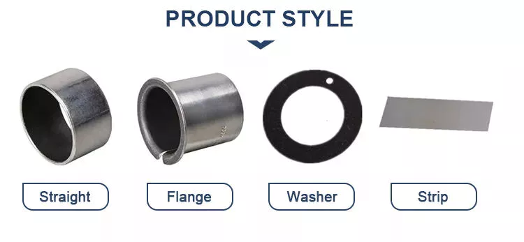
our description :Fits cat 1 and 2 three-point linkage.
Operates with 18 tonnes of force.
Hardened splitting wedge for a long working life.
Two handed operation for safety.
Robust steel construction.
Operated via PTO pump and oil reservoir.
Suitable for logs of 1m in height (max.).

our advantage:A  whole complete set of production equipment lead to  short  lead time and better prices of machine.

Guarantee 1 year warranty of all our products.

Produce machines according to any requirements from our customers.

New machines will be developed  every year.

Every model of our machine will be tested before the delivery to the port.

If you want to visit our factory, our boss will give you a best reception.
 

Helical, Straight-Cut, and Spiral-Bevel Gears

If you are planning to use bevel gears in your machine, you need to understand the differences between Helical, Straight-cut, and Spiral bevel gears. This article will introduce you to these gears, as well as their applications. The article will also discuss the benefits and disadvantages of each type of bevel gear. Once you know the differences, you can choose the right gear for your machine. It is easy to learn about spiral bevel gears.
gear

Spiral bevel gear

Spiral bevel gears play a critical role in the aeronautical transmission system. Their failure can cause devastating accidents. Therefore, accurate detection and fault analysis are necessary for maximizing gear system efficiency. This article will discuss the role of computer aided tooth contact analysis in fault detection and meshing pinion position errors. You can use this method to detect problems in spiral bevel gears. Further, you will learn about its application in other transmission systems.
Spiral bevel gears are designed to mesh the gear teeth more slowly and appropriately. Compared to straight bevel gears, spiral bevel gears are less expensive to manufacture with CNC machining. Spiral bevel gears have a wide range of applications and can even be used to reduce the size of drive shafts and bearings. There are many advantages to spiral bevel gears, but most of them are low-cost.
This type of bevel gear has 3 basic elements: the pinion-gear pair, the load machine, and the output shaft. Each of these is in torsion. Torsional stiffness accounts for the elasticity of the system. Spiral bevel gears are ideal for applications requiring tight backlash monitoring and high-speed operations. CZPT precision machining and adjustable locknuts reduce backlash and allow for precise adjustments. This reduces maintenance and maximizes drive lifespan.
Spiral bevel gears are useful for both high-speed and low-speed applications. High-speed applications require spiral bevel gears for maximum efficiency and speed. They are also ideal for high-speed and high torque, as they can reduce rpm without affecting the vehicle's speed. They are also great for transferring power between 2 shafts. Spiral bevel gears are widely used in automotive gears, construction equipment, and a variety of industrial applications.

Hypoid bevel gear

The Hypoid bevel gear is similar to the spiral bevel gear but differs in the shape of the teeth and pinion. The smallest ratio would result in the lowest gear reduction. A Hypoid bevel gear is very durable and efficient. It can be used in confined spaces and weighs less than an equivalent cylindrical gear. It is also a popular choice for high-torque applications. The Hypoid bevel gear is a good choice for applications requiring a high level of speed and torque.
The Hypoid bevel gear has multiple teeth that mesh with each other at the same time. Because of this, the gear transmits torque with very little noise. This allows it to transfer a higher torque with less noise. However, it must be noted that a Hypoid bevel gear is usually more expensive than a spiral bevel gear. The cost of a Hypoid bevel gear is higher, but its benefits make it a popular choice for some applications.
A Hypoid bevel gear can be made of several types. They may differ in the number of teeth and their spiral angles. In general, the smaller hypoid gear has a larger pinion than its counterpart. This means that the hypoid gear is more efficient and stronger than its bevel cousin. It can even be nearly silent if it is well lubricated. Once you've made the decision to get a Hypoid bevel gear, be sure to read up on its benefits.
Another common application for a Hypoid bevel gear is in automobiles. These gears are commonly used in the differential in automobiles and trucks. The torque transfer characteristics of the Hypoid gear system make it an excellent choice for many applications. In addition to maximizing efficiency, Hypoid gears also provide smoothness and efficiency. While some people may argue that a spiral bevel gear set is better, this is not an ideal solution for most automobile assemblies.
gear

Helical bevel gear

Compared to helical worm gears, helical bevel gears have a small, compact housing and are structurally optimized. They can be mounted in various ways and feature double chamber shaft seals. In addition, the diameter of the shaft and flange of a helical bevel gear is comparable to that of a worm gear. The gear box of a helical bevel gear unit can be as small as 1.6 inches, or as large as 8 cubic feet.
The main characteristic of helical bevel gears is that the teeth on the driver gear are twisted to the left and the helical arc gears have a similar design. In addition to the backlash, the teeth of bevel gears are twisted in a clockwise and counterclockwise direction, depending on the number of helical bevels in the bevel. It is important to note that the tooth contact of a helical bevel gear will be reduced by about 10 to 20 percent if there is no offset between the 2 gears.
In order to create a helical bevel gear, you need to first define the gear and shaft geometry. Once the geometry has been defined, you can proceed to add bosses and perforations. Then, specify the X-Y plane for both the gear and the shaft. Then, the cross section of the gear will be the basis for the solid created after revolution around the X-axis. This way, you can make sure that your gear will be compatible with the pinion.
The development of CNC machines and additive manufacturing processes has greatly simplified the manufacturing process for helical bevel gears. Today, it is possible to design an unlimited number of bevel gear geometry using high-tech machinery. By utilizing the kinematics of a CNC machine center, you can create an unlimited number of gears with the perfect geometry. In the process, you can make both helical bevel gears and spiral bevel gears.

Straight-cut bevel gear

A straight-cut bevel gear is the easiest to manufacture. The first method of manufacturing a straight bevel gear was to use a planer with an indexing head. Later, more efficient methods of manufacturing straight bevel gears were introduced, such as the Revacycle system and the Coniflex system. The latter method is used by CZPT. Here are some of the main benefits of using a straight-cut bevel gear.
A straight-cut bevel gear is defined by its teeth that intersect at the axis of the gear when extended. Straight-cut bevel gears are usually tapered in thickness, with the outer part being larger than the inner portion. Straight-cut bevel gears exhibit instantaneous lines of contact, and are best suited for low-speed, static-load applications. A common application for straight-cut bevel gears is in the differential systems of automobiles.
After being machined, straight-cut bevel gears undergo heat treatment. Case carburizing produces gears with surfaces of 60-63 Rc. Using this method, the pinion is 3 Rc harder than the gear to equalize wear. Flare hardening, flame hardening, and induction hardening methods are rarely used. Finish machining includes turning the outer and inner diameters and special machining processes.
The teeth of a straight-cut bevel gear experience impact and shock loading. Because the teeth of both gears come into contact abruptly, this leads to excessive noise and vibration. The latter limits the speed and power transmission capacity of the gear. On the other hand, a spiral-cut bevel gear experiences gradual but less-destructive loading. It can be used for high-speed applications, but it should be noted that a spiral-cut bevel gear is more complicated to manufacture.
gear

Spur-cut bevel gear

CZPT stocks bevel gears in spiral and straight tooth configurations, in a range of ratios from 1.5 to five. They are also highly remachinable except for the teeth. Spiral bevel gears have a low helix angle and excellent precision properties. CZPT stock bevel gears are manufactured using state-of-the-art technologies and know-how. Compared with spur-cut gears, these have a longer life span.
To determine the strength and durability of a spur-cut bevel gear, you can calculate its MA (mechanical advantage), surface durability (SD), and tooth number (Nb). These values will vary depending on the design and application environment. You can consult the corresponding guides, white papers, and technical specifications to find the best gear for your needs. In addition, CZPT offers a Supplier Discovery Platform that allows you to discover more than 500,000 suppliers.
Another type of spur gear is the double helical gear. It has both left-hand and right-hand helical teeth. This design balances thrust forces and provides extra gear shear area. Helical gears, on the other hand, feature spiral-cut teeth. While both types of gears may generate significant noise and vibration, helical gears are more efficient for high-speed applications. Spur-cut bevel gears may also cause similar effects.
In addition to diametral pitch, the addendum and dedendum have other important properties. The dedendum is the depth of the teeth below the pitch circle. This diameter is the key to determining the center distance between 2 spur gears. The radius of each pitch circle is equal to the entire depth of the spur gear. Spur gears often use the addendum and dedendum angles to describe the teeth.

China supplier Hydraulic Commercial Log Splitter 3 Point Hitch for Tractor     with Free Design CustomChina supplier Hydraulic Commercial Log Splitter 3 Point Hitch for Tractor     with Free Design Custom

China Hot selling Hydraulic Heavy Duty Wood Chipper with 3 Point Hitch for Tractor wholesaler

Product Description

Model BX92RS
Chipper Capacity 250mm/10''
Chipper Housing Opening 10''x15''
No.of Knives 4
Rotor Size 36''
Feeding System Feed Hydraulic Feed
Hopper Folded 66''Lx68''Wx90''H
Hopper Opening 25''x25''
Mounting System 3 Point Hitch
Discharge Hood Rotation 360˚
Discharge Hood Height 90''
Structure Weight 625kg
Tractor HP 70-120hp

  
our description :The  BX92RS Hydraulic PTO Wood Chipper has a 9″ chipper capacity and a 10.5″ x 14″ chipper housing opening and is fitted with a 125kg heavyweight Rotor.  This model Wood Chipper has a direct hydraulic feed from the tractor hydraulic rear connection plugs.
Direct PTO drive that operates as a fix drive system and without the use of gears and belt drives and this model is fitted standard with easily replaceable blades by removing 3 removable bolt for simple and easy access to the top half of housing and the hopper can also be fully opened with 2 removable bolts. 
This model Wood Chipper has a full hydraulic feed system that allows for fast, medium or slow flow rate settings and with its 3 feed setting options from feed direction of forward, reverse and neutral settings.
The Hydraulic model allows for consistent chipping as the Hydraulic System has double support arms from both sides of the internal hopper with drive force from its hydraulic motor and with a Dual Barrel System that enables dragging motion for consistent cutting.
The Hydraulic Feed Chipper model is a simple and low maintenance chipper and CZPT to handle the hardest and knotted wood.


our advantage:A  whole complete set of production equipment lead to  short  lead time and better prices of machine.

Guarantee 1 year warranty of all our products.

Produce machines according to any requirements from our customers.

New machines will be developed  every year.

Every model of our machine will be tested before the delivery to the port.

If you want to visit our factory, our boss will give you a best reception.
 

What is the purpose of the bushing?

If you notice the truck making noises when cornering, the bushings may be worn. You may need to replace the ball joint or stabilizer bar, but a simple inspection will reveal that the noise is coming from the bushing. The noise from a worn bushing on a metal joint can mimic the sound of other problems in the suspension, such as a loose stabilizer bar or a failed ball joint.
bushing

Function

What is the purpose of the bushing? They play an important role in the operation of various mechanical parts. Their main functions include reducing the clearance between the shaft and the bearing and reducing the leakage of the valve. Bushings are used in different ways to ensure smooth operation and longevity. However, some new designers don't appreciate the functionality of the case. So let's discuss these features. Some of their most common applications are listed below.
First, the shell does a lot of things. They reduce noise, control vibration, and provide amazing protection for all kinds of industrial equipment. Large industrial equipment faces more wear, vibration and noise, which can render it completely inoperable. Bushings help prevent this by reducing noise and vibration. Bushing sets also extend equipment life and improve its performance. Therefore, you should not underestimate the importance of the casing in your device.
Another common function of bushings is to support components during assembly. In other words, the bushing reduces the risk of machine wear. In addition to this, they are superior to bearings, which are notoriously expensive to maintain. However, they are still useful, and their versatility cannot be overemphasized. If you're considering installing one, you'll be glad you did! These products have become a necessity in the modern industrial world. If you're wondering how to choose one, here are some of the most common bushing uses.
Electrical bushings are an important part of many electrical equipment. They carry high voltage currents through the enclosure and provide an insulating barrier between live conductors and metal bodies at ground potential. They are made of a central conductive rod (usually copper or aluminum) and surrounding insulators made of composite resin silicone rubber. Additionally, the bushings are made of various materials. Whether copper, aluminum or plastic, they are an important part of many types of electrical equipment.

type

There are several different types of bushings on the market today. They may be cheap but they are of good quality. These products can be used in telephones, cable television, computer data lines and alarm systems. The key to buying these products online is finding the right appliance store and choosing a high-quality product. An online appliance store should have comprehensive information and ease of use. For the right electrical bushing, you should look for reliable online stores with the best prices and high quality products.
Capacitive grading bushings use conductive foils inserted into paper to stabilize the electric field and balance the internal energy of the bushing. The conductive foil acts as a capacitive element, connecting the high voltage conductor to ground. These types of bushings are sometimes referred to as capacitor grade bushings. Capacitive grading bushings are usually made of paper impregnated with epoxy resin or mineral oil.
When buying enclosures, you should know how they are used. Unlike ball bearings, bushings should be stored upright so that they are in the correct working position. This is because horizontal placement can cause air bubbles to form in the fill insulation. It is also important to store the bushing properly to prevent damage. The wrong way to store these components can result in costly repairs.
In addition to the physical structure, the bushing insulation must also be effective over the long term. It must resist partial discharge and working electric field stress. The material and design of the bushing can vary widely. Early on, porcelain-based materials were popular in bushing designs. Porcelain was chosen because of its low cost of production and very low linear expansion. Ceramic bushings, on the other hand, require a lot of metal fittings and flexible seals.
bushing

Durability

The RIG 3 Bushing Durability Test Standard simulates real-world service conditions for automotive bushings. This three-channel test standard varies casing loads and stresses by applying a range of different load conditions and various control factors. This test is critical to the durability of the case, as it accurately reproduces the dynamic loads that occur during normal use. This test is a key component of the automotive industry and is widely used in many industries.
The Advanced Casing Model has 5 modules to address asymmetry, nonlinearity, and hysteresis. This model also represents the CZPT lag model. The model can be parameterized in the time domain using MATLAB, and the results can be exported to other simulation software. The developed bushing model is a key component in the durability and performance of vehicle suspension components.
A conductive material is coated on the inner surface of the sleeve. The coating is chosen to conduct a certain amount of current. The conductive path extends from the blade spacer 126 to the sleeve projecting edge 204 and then through the housing 62 to the ground. The coating is made of a low friction material and acts as a wear surface against the bushing sidewall 212 and the housing 62 .
Another important factor in a bushing's durability is its ability to friction. The higher the operating speed, the greater the load on the bushing. Since bushings are designed for lighter loads and slower speeds, they cannot handle large loads at high speeds. The P-max or V-max value of a bushing is its maximum load or speed at 0 rpm. The PV value must be lower than the manufacturer's PV value.

price

If you need to replace the bushing on the control arm, you should understand the cost involved. This repair can be expensive, depending on the make and model of your car. Generally, you should pay between $105 and $180 for a replacement. However, you can choose to have it done by a mechanic at a lower cost. The labor cost for this job can be around $160, depending on your automaker.
The cost of replacing the control arm bushings can range from $200 on the low end to $500 on a luxury car. While parts are cheap, labor costs are the highest. Mechanics had to remove suspension and wheel assemblies to replace bushings. If you have some mechanical knowledge, you can replace the bushing yourself. Control arm bushings on the wheel side are usually about $20 each. Still, if you're not a mechanic, you can save money by doing it yourself.
bushing

Install

Press-fit bushings are installed using a retaining ring with a diameter 0.3/0.4 mm larger than the inner diameter of the bushing. To ensure accurate installation, use a mechanically driven, pneumatic or hydraulic drill and insert the bushing into the appropriate hole. This process is best done using mounting holes with drilled holes for the clamps. Make sure the mounting hole is in the center of the bushing and free of debris.
Once the bushing is positioned, use a vise to install its nut. A cold bushing will compress and fit the shell better. Place the sleeve in the refrigerator for at least 24 hours to aid installation. After removing the bushing from the refrigerator, make sure it has enough diameter to fit into the enclosure. Next, place the opposite socket into the enclosure and use it as a stand. After a few minutes, the bushing should be fully seated in the housing.
Install the new bushing into the housing hole. If the previous 1 had a metal case, insert the new 1 through the taper. Always lubricate the inner and outer surfaces of the bushing. Then, apply pressure to the inner metal sleeve of the new bushing. You may notice that the new bushing does not exactly match the housing hole. However, that's okay because the outer diameter of the bushing is larger than the outer diameter of the hub drive.
The installation of the bushing requires the use of the hydraulic unit 16 . Hydraulic unit 16 is located near the #1 journal of the camshaft and extends from #2 to #7. Hydraulic fluid forces piston 22 away from the outer end of cylinder 20 and pushes shaft 14 forward. The shaft is then moved forward, pushing the bushing 17 onto the piston. Multiple bushings can be installed in a single engine.

China Hot selling Hydraulic Heavy Duty Wood Chipper with 3 Point Hitch for Tractor     wholesaler China Hot selling Hydraulic Heavy Duty Wood Chipper with 3 Point Hitch for Tractor     wholesaler

China factory 3-Point Hitch Tractor Rear Mounted Transport CZPT Box near me supplier

Product Description

1. Perfect when collecting firewood and clearing other debris around your property.


2.  Ideal for moving tools, fuel tanks, sprayers, generators and dirt around even the roughest terrain.
 

3. Easy to store.
 

4. Re-enforced rear base for reversing into loose materials for easy loading.
 

5. Heavy duty design.
 

6. High strength rear base for reversign into loose soil mounds.


Model

3.5TSCP

4TSCP

5TSCP

 6TSCP

7TSCP

Length

1050

1200

1500

 1800

2100

Tractor HP

25-40

25-45

25-55

 35-60

40-60

Hydraulic

Optional


Q1. What are your terms of packing?

A: Generally, we pack our goods in bulks or wooden box or steel crane, suitable for shipping container.

Q2. What is your terms of payment?

A: T/T 30% as deposit, and 70% against BL Copy. We'll show you the photos of the products and packages before you pay the balance.

Q3. What are your terms of delivery?

A: EXW, FOB, CFR, CIF.

Q4. How about your delivery time?

A: Generally, it will take 30-40 days after receiving your advance payment for containers. The specific delivery time depends 

on the items and the quantity of your order. 

Q5. Can you produce according to the samples?

A: Yes, we can produce by your samples or technical drawings.

Q6. What is your sample policy?

A: We can supply the sample if we have ready parts in stock.


Stiffness and Torsional Vibration of Spline-Couplings

In this paper, we describe some basic characteristics of spline-coupling and examine its torsional vibration behavior. We also explore the effect of spline misalignment on rotor-spline coupling. These results will assist in the design of improved spline-coupling systems for various applications. The results are presented in Table 1.
splineshaft

Stiffness of spline-coupling

The stiffness of a spline-coupling is a function of the meshing force between the splines in a rotor-spline coupling system and the static vibration displacement. The meshing force depends on the coupling parameters such as the transmitting torque and the spline thickness. It increases nonlinearly with the spline thickness.
A simplified spline-coupling model can be used to evaluate the load distribution of splines under vibration and transient loads. The axle spline sleeve is displaced a z-direction and a resistance moment T is applied to the outer face of the sleeve. This simple model can satisfy a wide range of engineering requirements but may suffer from complex loading conditions. Its asymmetric clearance may affect its engagement behavior and stress distribution patterns.
The results of the simulations show that the maximum vibration acceleration in both Figures 10 and 22 was 3.03 g/s. This results indicate that a misalignment in the circumferential direction increases the instantaneous impact. Asymmetry in the coupling geometry is also found in the meshing. The right-side spline's teeth mesh tightly while those on the left side are misaligned.
Considering the spline-coupling geometry, a semi-analytical model is used to compute stiffness. This model is a simplified form of a classical spline-coupling model, with submatrices defining the shape and stiffness of the joint. As the design clearance is a known value, the stiffness of a spline-coupling system can be analyzed using the same formula.
The results of the simulations also show that the spline-coupling system can be modeled using MASTA, a high-level commercial CAE tool for transmission analysis. In this case, the spline segments were modeled as a series of spline segments with variable stiffness, which was calculated based on the initial gap between spline teeth. Then, the spline segments were modelled as a series of splines of increasing stiffness, accounting for different manufacturing variations. The resulting analysis of the spline-coupling geometry is compared to those of the finite-element approach.
Despite the high stiffness of a spline-coupling system, the contact status of the contact surfaces often changes. In addition, spline coupling affects the lateral vibration and deformation of the rotor. However, stiffness nonlinearity is not well studied in splined rotors because of the lack of a fully analytical model.
splineshaft

Characteristics of spline-coupling

The study of spline-coupling involves a number of design factors. These include weight, materials, and performance requirements. Weight is particularly important in the aeronautics field. Weight is often an issue for design engineers because materials have varying dimensional stability, weight, and durability. Additionally, space constraints and other configuration restrictions may require the use of spline-couplings in certain applications.
The main parameters to consider for any spline-coupling design are the maximum principal stress, the maldistribution factor, and the maximum tooth-bearing stress. The magnitude of each of these parameters must be smaller than or equal to the external spline diameter, in order to provide stability. The outer diameter of the spline must be at least 4 inches larger than the inner diameter of the spline.
Once the physical design is validated, the spline coupling knowledge base is created. This model is pre-programmed and stores the design parameter signals, including performance and manufacturing constraints. It then compares the parameter values to the design rule signals, and constructs a geometric representation of the spline coupling. A visual model is created from the input signals, and can be manipulated by changing different parameters and specifications.
The stiffness of a spline joint is another important parameter for determining the spline-coupling stiffness. The stiffness distribution of the spline joint affects the rotor's lateral vibration and deformation. A finite element method is a useful technique for obtaining lateral stiffness of spline joints. This method involves many mesh refinements and requires a high computational cost.
The diameter of the spline-coupling must be large enough to transmit the torque. A spline with a larger diameter may have greater torque-transmitting capacity because it has a smaller circumference. However, the larger diameter of a spline is thinner than the shaft, and the latter may be more suitable if the torque is spread over a greater number of teeth.
Spline-couplings are classified according to their tooth profile along the axial and radial directions. The radial and axial tooth profiles affect the component's behavior and wear damage. Splines with a crowned tooth profile are prone to angular misalignment. Typically, these spline-couplings are oversized to ensure durability and safety.

Stiffness of spline-coupling in torsional vibration analysis

This article presents a general framework for the study of torsional vibration caused by the stiffness of spline-couplings in aero-engines. It is based on a previous study on spline-couplings. It is characterized by the following 3 factors: bending stiffness, total flexibility, and tangential stiffness. The first criterion is the equivalent diameter of external and internal splines. Both the spline-coupling stiffness and the displacement of splines are evaluated by using the derivative of the total flexibility.
The stiffness of a spline joint can vary based on the distribution of load along the spline. Variables affecting the stiffness of spline joints include the torque level, tooth indexing errors, and misalignment. To explore the effects of these variables, an analytical formula is developed. The method is applicable for various kinds of spline joints, such as splines with multiple components.
Despite the difficulty of calculating spline-coupling stiffness, it is possible to model the contact between the teeth of the shaft and the hub using an analytical approach. This approach helps in determining key magnitudes of coupling operation such as contact peak pressures, reaction moments, and angular momentum. This approach allows for accurate results for spline-couplings and is suitable for both torsional vibration and structural vibration analysis.
The stiffness of spline-coupling is commonly assumed to be rigid in dynamic models. However, various dynamic phenomena associated with spline joints must be captured in high-fidelity drivetrain models. To accomplish this, a general analytical stiffness formulation is proposed based on a semi-analytical spline load distribution model. The resulting stiffness matrix contains radial and tilting stiffness values as well as torsional stiffness. The analysis is further simplified with the blockwise inversion method.
It is essential to consider the torsional vibration of a power transmission system before selecting the coupling. An accurate analysis of torsional vibration is crucial for coupling safety. This article also discusses case studies of spline shaft wear and torsionally-induced failures. The discussion will conclude with the development of a robust and efficient method to simulate these problems in real-life scenarios.
splineshaft

Effect of spline misalignment on rotor-spline coupling

In this study, the effect of spline misalignment in rotor-spline coupling is investigated. The stability boundary and mechanism of rotor instability are analyzed. We find that the meshing force of a misaligned spline coupling increases nonlinearly with spline thickness. The results demonstrate that the misalignment is responsible for the instability of the rotor-spline coupling system.
An intentional spline misalignment is introduced to achieve an interference fit and zero backlash condition. This leads to uneven load distribution among the spline teeth. A further spline misalignment of 50um can result in rotor-spline coupling failure. The maximum tensile root stress shifted to the left under this condition.
Positive spline misalignment increases the gear mesh misalignment. Conversely, negative spline misalignment has no effect. The right-handed spline misalignment is opposite to the helix hand. The high contact area is moved from the center to the left side. In both cases, gear mesh is misaligned due to deflection and tilting of the gear under load.
This variation of the tooth surface is measured as the change in clearance in the transverse plain. The radial and axial clearance values are the same, while the difference between the 2 is less. In addition to the frictional force, the axial clearance of the splines is the same, which increases the gear mesh misalignment. Hence, the same procedure can be used to determine the frictional force of a rotor-spline coupling.
Gear mesh misalignment influences spline-rotor coupling performance. This misalignment changes the distribution of the gear mesh and alters contact and bending stresses. Therefore, it is essential to understand the effects of misalignment in spline couplings. Using a simplified system of helical gear pair, Hong et al. examined the load distribution along the tooth interface of the spline. This misalignment caused the flank contact pattern to change. The misaligned teeth exhibited deflection under load and developed a tilting moment on the gear.
The effect of spline misalignment in rotor-spline couplings is minimized by using a mechanism that reduces backlash. The mechanism comprises cooperably splined male and female members. One member is formed by 2 coaxially aligned splined segments with end surfaces shaped to engage in sliding relationship. The connecting device applies axial loads to these segments, causing them to rotate relative to 1 another.

China factory 3-Point Hitch Tractor Rear Mounted Transport CZPT Box     near me supplier China factory 3-Point Hitch Tractor Rear Mounted Transport CZPT Box     near me supplier

China Good quality 3 Point Hitch Furrow Plow Share Plough for Tractor near me shop

Product Description

1. The plough is designed to roll soil over so you can start preparing your garden in the fall. The plough is heavy enough to dig into almost any soil and the double rolled moldboard will prevent the soil from sticking too tight to the moldboard, ensuring that the vegetation gets rolled under a nice layer of topsoil.
 

2. This 3point, Cat 1 is easy to attach and adjust to till your garden or field in no time.
 

3. Applicable for day sand soil. With whole hanging, simple structure good working.


Model

PF1

 PF2  PF3

Plow Disc

1

 2   3

Tractor HP

15-25

18-30  20-35

Tractor Hitch

Cat. 1

 Cat. 1  Cat. 1


Q1. What are your terms of packing?

A: Generally, we pack our goods in bulks or wooden box or steel crane, suitable for shipping container.

Q2. What is your terms of payment?

A: T/T 30% as deposit, and 70% against BL Copy. We'll show you the photos of the products and packages before you pay the balance.

Q3. What are your terms of delivery?

A: EXW, FOB, CFR, CIF.

Q4. How about your delivery time?

A: Generally, it will take 30-40 days after receiving your advance payment for containers. The specific delivery time depends 

on the items and the quantity of your order. 

Q5. Can you produce according to the samples?

A: Yes, we can produce by your samples or technical drawings.

Q6. What is your sample policy?

A: We can supply the sample if we have ready parts in stock.


Types of Ball Bearings

There are several types of ball bearings: Double-row angular contact, Four-point contact, Self-aligning, and Ceramic hybrid. Here's a brief description of each. For more information, read our article about Double-row angular contact ball bearings. You'll be better informed about how they're made. Also, learn about how the cages that hold the balls in place are secured with rivets.

Double-row, angular-contact bearing

Double-row, angular-contact ball bearings are similar in their contact surfaces in 1 direction, and the 2 pairs of bearings are installed axially opposite to 1 another. This design allows them to support combined loads in axial and radial directions. These types of bearings are used for high-precision, high-speed applications. They can be used in everything from turbines to dentistry equipment. Double-row, angular-contact bearings are available at Grainger, as are single-row versions.
Double-row, angular-contact ball bearings are a popular option for applications where high precision and high speed are required. The design features of these bearings are ideal for applications with axial space restrictions. In contrast, they are smaller than 2 single-row angular-contact bearings and are available in steel, polyamide, or brass cages. Whether you need a cage for high speed or hard operating conditions is up to you. If you are unsure about the right cage for your application, contact Schaeffler.
Single-row angular-contact ball bearings are the most common type of bearings. Double-row bearings are also available with a shielded outer ring, which protects the balls inside the bearing from external contaminants. Because these double-row bearings are a good choice for applications requiring high performance, they are often the most affordable option. They offer similar performance as single-row bearings but are much more rigid.
Preloading is a key performance characteristic for double-row angular-contact ball bearings. Preloading can decrease the service life of double-row angular-contact ball bearings by up to 380 percent. Alternatively, you can preload double-row angular-contact ball bearings by placing spacers between their outer rings. Good double-row angular-contact bearing installation will increase working accuracy and bearing life.
bearing

Four-point contact ball bearing

The Four Point Contact Ball Bearing Market can be segmented into 3 types: 35 Degree, 45 Degree, and Other. The 35 Degree segment is expected to witness the fastest growth over the next few years, owing to its increased operational speed and competence in axial and radial axis load handling. Other types of four-point contact ball bearings include the Miniature and Deep Groove varieties. These are widely used in automobiles, aerospace, and other industries.
These bearings are designed for oil-free screw compressors, and they feature an outer-ring guided brass cage to reduce friction and increase running accuracy. In addition, they have lower maintenance costs compared to conventional bearings. However, they have a higher mean roughness value than their counterparts. High-speed operations require high-speed bearings that can withstand fast speed changes. This is because of the higher friction rate, which results from four-point contact.
The Four-Point Contact Ball Bearing is a highly versatile product, as it can handle radial, thrust, and moment loads. Because of this, it is often the first choice for slow to moderate-speed applications. This design also has a simplified assembly process, requiring only a single double-half-turn to install. It is the first choice of many automotive OEMs because it is extremely efficient. If you want a ball bearing with these benefits, you should contact a local bearing company.
The Four-Point Contact Ball Bearing Market will continue to grow despite a tough economy and volatile trade conditions. Demand for automotive and aerospace components is expected to grow alongside a variety of technological advancements. Meanwhile, demand for energy-efficient products will continue to increase with changes in trade policy, an imbalance in the supply-side ecosystem, and geopolitical risk. And while all these factors will continue to drive the market growth, a few challenges are worth considering.
The Four-Point Contact Bearing is designed with the same basic structure as its two-point counterpart. In a four-point contact ball bearing, 1 ball can have 4 distinct points of contact with 2 rings. Two of these contact points may be in diagonal position. The 2 remaining contact points change position and accommodate radial loads. Consequently, the Four-Point Contact Bearing is more flexible and robust than its two-point counterparts.
bearing

Self-aligning ball bearing

The self-aligning ball bearing is an incredibly useful tool in many industries. This type of bearing has a sealing lip that makes contact with a smooth chamfer on the inner ring. Because of the self-aligning nature of these bearings, they are not prone to misalignment. They can withstand temperatures ranging from -30°C to 120°C and should not be heated prior to installation.
A self-aligning ball bearing is an elastomer-based spherical-shaped bearing with 2 rows of rolling elements. These bearings can accommodate large radial loads, and their outer ring raceway is curved to provide a spherical effect. The inner ring, or cage, can be either cylindrical or conical. The inner diameter of a self-aligning ball bearing is normally cylindrical, but some are conical. They typically have 3 oil holes.
When choosing a self-aligning ball bearing, look for a model with a large enough bearing diameter to accommodate the shaft's bending. Self-aligning bearings may also be interchangeable with standard ball bearing assemblies. You can find individual values in manufacturer catalogues. These bearings are useful in limited applications, although they are not necessarily ideal for everything. For example, in applications where combined loads are the main concern, self-aligning ball bearings should only be used if the application requires minimal misalignment.
A self-aligning ball bearing is a highly-efficient, energy-efficient solution for a variety of applications. It is a simple, low-maintenance solution that makes your life easier. Its unique outer raceway allows restraining springs to absorb the deflection that is common in other bearings. The result is a cooler, smoother running vehicle. It also helps prevent misalignment, which makes it ideal for use in many applications.
The SKF self-aligning ball bearing is an excellent choice for applications involving heavy deflection of the shaft. They are the lowest-friction bearing available. Their steel plate reinforced seals prevent them from separating from the shaft during operation. They are also resistant to oil, making them the perfect solution for high-speed applications. In addition to this, they are designed to work in a wide range of temperatures.
bearing

Ceramic hybrid ball bearing

A hybrid ball bearing made from a combination of steel and ceramics is a good option for high-speed applications requiring electrical isolation. This combination offers an extended lifespan and minimal electrical corrosion or seizure risk. In addition, the hybrid ball bearings have less friction than steel bearings and can operate at low speeds. To learn more about this hybrid type of bearing, continue reading. We'll also discuss how it can help your application.
Full ceramic balls are generally harder than steel, but they do have lower density, meaning they're not subject to the same high centrifugal forces as steel balls. These benefits make ceramic ball bearings much more durable, with long lifespans. Both full and hybrid ceramic ball bearings are available from CZPT. Read on to learn more about each type. Here's a look at some of the benefits of each. You'll be pleasantly surprised.
A hybrid ball bearing consists of steel inner and outer rings and a ceramic ball. It can withstand high speeds and loads, but it's also designed to operate in extreme temperatures. This hybrid ball bearing also requires minimal lubrication and is suitable for a variety of applications. Because of its unique characteristics, hybrid bearings are lightweight and hard, and they spin faster than steel balls. But how do you choose the right 1 for your application?
A ceramic ball bearing is better than a steel 1 for many applications. Its greater speed capability and lower friction allow it to operate at higher speeds than steel balls. It is also less sensitive to fluctuations in lubrication conditions than steel balls. They also tend to be cheaper, so it makes sense to invest in one. It's worth your while. They last longer, and they don't require a run-in period.
A hybrid ball bearing is the best choice for electric spindles with high speed and heavy loads. A hybrid ceramic ball bearing has the advantage of low heat and high stiffness, and can operate at high speeds and loads. This thesis explores the dynamic characteristics of a hybrid ceramic ball bearing, including analysis calculations and experiment verification. The results provide reliable data and lay the foundation for professional spindle optimum design tests. It is a worthy addition to any machine shop.

China Good quality 3 Point Hitch Furrow Plow Share Plough for Tractor     near me shop China Good quality 3 Point Hitch Furrow Plow Share Plough for Tractor     near me shop

China Standard Tractor 3 Point Quick Hitch Move High Quality Agricultural Attachment near me shop

Product Description

1. This tractor quick hich lets you quickly and easily attach and release three-point implements without leaving your tractor seat.
 

2. Heavy duty steel construction.
 

3. Adjustable top link bracket.

4. With the Quick Hitch attached, it's easy to hook up all sorts of equipment - simply pull open the lock on the Quick Hitch, back up to the equipment and lift it. Then lower the handles into place, hook up the PTO or hydraulics, if required, and you're ready to get some work done.


Model Tractor HP Tractor Hitch
QH-0 Up to 30HP Cat 0
QH-1 Up to 50HP Cat 1
QH-2 Up to 100HP Cat 2
QH-3 Up to 225HP Cat 3


Q1. What are your terms of packing?

A: Generally, we pack our goods in bulks or wooden box or steel crane, suitable for shipping container.

Q2. What is your terms of payment?

A: T/T 30% as deposit, and 70% against BL Copy. We'll show you the photos of the products and packages before you pay the balance.

Q3. What are your terms of delivery?

A: EXW, FOB, CFR, CIF.

Q4. How about your delivery time?

A: Generally, it will take 30-40 days after receiving your advance payment for containers. The specific delivery time depends 

on the items and the quantity of your order. 

Q5. Can you produce according to the samples?

A: Yes, we can produce by your samples or technical drawings.

Q6. What is your sample policy?

A: We can supply the sample if we have ready parts in stock.


Types of Ball Bearings

If you're looking to purchase a new ball bearing, there are many different types available. Learn about Single-row designs, Ceramic hybrid bearings, and Self-aligning ball bearings. You can also choose from stainless steel or single-row designs. Then, read about the different types of materials available to you. You'll have an easier time making a decision. After all, you won't have to worry about maintaining your new ball bearing, since it will be maintained by your supplier.
bearing

Single-row designs

Ball bearings with a single-row design have a high load-carrying capacity. They are used in applications where high loads must be handled smoothly. A single-row design is a good choice when the material's properties require high load-carrying capacity but limited axial load capability. Single-row designs use 2 bearings with similar design features, but they have different mounting methods. Single-row designs can be adjusted either against 1 another to accommodate axial loads.
The single-row design is suitable for high-speed applications, but also has some disadvantages. The contact angle a is the angle between the radial plane and contact line. The larger the angle, the higher the axial load carrying capacity of the bearing. Single-row angular contact ball bearings are suitable for higher axial forces. Single-row angular contact ball bearings have a single-row design and support high axial forces in 1 direction. Single-row ball bearings are available in both pressed steel and machined steel cages.
Angular contact ball bearings with a single row feature a cage made of fiber-glass reinforced polyamide 66. These are available in diameters up to 130 mm. Four-point angular contact ball bearings use brass, steel, or brass plate. They have good running properties and a low coefficient of linear expansion. Single-row designs are easy to mount and are widely available. Alternatively, they can be mounted with a universal match design, which allows them to be easily adjusted.
One-row angular contact ball bearings are generally not suitable for angular misalignments because they are unsuitable for compensation of angular misalignments. Misalignments cause internal forces in the bearing which reduce its radial load capacity and life expectancy. This type of bearing is not suitable for adjacent mounting as it increases the chances of misalignment. However, it is a suitable choice for applications where only 1 bearing is required per bearing position.

Ceramic hybrid bearings

While all-ceramic bearings are limited to very specialized applications, Si3N4-based hybrid bearings are finding use in a wide range of high-speed machines. Compared to steel, ceramics are less susceptible to centrifugal forces, which are directly proportional to the mass of the balls. Because Si3N4 replacement balls have a lower density than steel, these bearings reduce the stress placed on the outer race.
The benefits of hybrid bearings are clear: they allow for higher speeds and loads than full-ceramic bearings, and they require no lubrication. Because of their many benefits, many industrial equipment operators are switching to these innovative bearings. CBR is 1 company that specializes in ceramic hybrid bearings and can help you find the best product for your application. If you are thinking about purchasing ceramic bearings for your next machine, here are some things you need to know about them.
A ceramic ball bearing surface has an extremely low coefficient of friction, which is important for applications that require low friction and high speeds. Ceramic balls also have a higher hardness than steel balls, which increases their life. In addition to this, ceramic hybrid bearings have superior thermal properties, generating less heat even when spinning at high speeds. These properties make ceramic hybrid bearings an ideal choice for high-speed machinery, especially electric motors. They are also suitable for applications that operate under water.
A ceramic ball hybrid bearing is much less susceptible to temperature fluctuations and wear. Because they are essentially indestructible, ceramic balls do not generate wear particles from the adhesive wear. They can run at significantly higher speeds than steel balls. Ceramic balls are also more resistant to moisture. For this reason, grease is a recommended lubricant in most ceramic bearing applications. These lubricants offer superior protection against moisture and corrosion. Further, they are available in many types.
bearing

Self-aligning ball bearings

A self-aligning ball bearing is 1 type of self-aligning bearing. These bearings are recommended for use in flex shaft systems. Their self-aligning feature prevents them from misaligning when in use. They can be used in both single and multiple-joint systems. In addition to self-aligning ball bearings, these units also feature flex shafts.
These self-aligning ball bearings come in a variety of configurations, including cylindrical, round, tapered, and straight bore. Their inner ring is tapered to meet specific tolerances. They are suitable for operating temperatures ranging from -30°F to 120°F. Their wide range of applications allows them to be used in general machinery, precision instruments, and low noise motors. In addition, they are available in a variety of outside diameters, widths, and internal clearances.
Self-aligning ball bearings have 2 rows of balls and 1 common sphered raceway in the outer ring. This enables them to automatically compensate for angular misalignment, which may be caused by machining and assembly errors or deflections. Compared to spherical roller bearings, these self-aligning ball bearings generate less friction. They run cooler even at high speeds. Self-aligning ball bearings also offer free engineering support.
Self-aligning ball bearings are designed for difficult shaft alignment. They are double-row, self-retaining units, with cylindrical or tapered bores. These bearings are available in open and sealed designs, and can also be used in applications with misalignment. They are also available with an outer ring that rotates in relation to the inner ring. When it comes to shaft misalignment, self-aligning ball bearings are a great solution.

Stainless steel

Stainless steel is a metal that resists corrosion and is highly durable. Its corrosion-resistant and water-resistance properties make it a good choice for bearings in food and marine applications. Additionally, stainless steel has hygienic benefits. Here are some of the benefits of stainless steel ball bearings. Read on to learn more about these amazing bearings! We've included some of the most common uses for stainless steel.
Hardness is important in a ball bearing. Steel uses the Rockwell C scale to measure hardness. A grade 25 steel ball bearing is accurate to 25 millionths of an inch, while a grade 5 ceramic bearing is less than a half-inch round. Although roundness is important, it shouldn't be overemphasized, as the bearing surfaces may not be as accurate as the grade of the metal. And remember, a higher price tag doesn't mean a better product.
Stainless steel ball bearings are available in a variety of alloys. The alloys used in manufacturing a stainless steel ball bearing vary in hardness, strength, and ductility. Stainless steel ball bearings have high corrosion-resistance properties. Additionally, they have long lubrication lives. These benefits make them a popular choice for industrial applications. These bearings are easy to maintain, reduce replacement costs, and offer corrosion resistance.
The NTN Sentinel Series is a premium line of stainless steel bearings. The solid lube is NSF H1 registered and prevents grease from leaching into food. It is also corrosion-resistant and doesn't need to be coated. The seals and slinger create a water-resistant barrier between the steel ball and the lubricant. It also adds safety and security to the bearing.
bearing

Plastic balls

For applications where noise and weight are major concerns, plastic balls are ideal. These non-magnetic balls are ideal for MRI X-ray machines and sensors. They are also easy to lubricate, and are non-magnetic. A polymer ball bearing is the lightest of all 3 types. This makes them a good choice for many industries. Read on to learn more. This article will introduce some of the advantages of plastic balls for ball bearings.
Although ceramic ball bearings are more durable and offer many advantages, they are more expensive than plastic. Fortunately, plastic ball bearings offer a cheaper alternative. These bearings feature all-plastic races and cages. Depending on the application, plastic balls can be used in applications involving chemicals. In these cases, plastic ball bearings are available with a C160 grade, which is safe for use in temperatures below 176 deg F.
Medical devices often require precision specialty balls, which are made of glass, stainless steel, and plastic. These bearings must meet stringent cleanliness requirements. To meet the most stringent requirements, they must undergo ultrasonic cleaning. These bearings are available in plastic raceways, and are also available with glass or stainless steel balls. Polyethylene balls are lightweight and can be used in a variety of applications. They can be ordered in different sizes and tolerances to meet specific requirements.
Plastic balls for ball bearings are often mounted into other parts, such as plastic wheels, pulleys, and housings. They can be seamlessly integrated into other parts of a machine, which reduces assembly time and improves affordability. One important advantage of plastic bearings is that they are rust-resistant. As such, they can be used in harsh environments without causing any damage. If a piece of equipment is exposed to extreme temperatures, polymers are the ideal choice.

China Standard Tractor 3 Point Quick Hitch Move High Quality Agricultural Attachment     near me shop China Standard Tractor 3 Point Quick Hitch Move High Quality Agricultural Attachment     near me shop

China Hot selling Farm Tractor Backhoe Digger 3 Point Hitch Backhoe wholesaler

Product Description

Product Description

 
Features:
-Side-shift boom
-Suits all types of tractors with Cat 1 or 2,3-point linkage kit
-Joustick style control console
-Tough and reliable hydraulic arm
-Individially controlled support legs
-Boom lockout pins for transport

MODEL BHS-175 BHS-195 BHS-225
Tractor HP 25-30hp 30-45hp 45-60hp
3-point linkage Cat-1 Cat-1 Cat-1
Structure Weight 520kg 560kg 750kg
(A) Working length 2600mm 2900mm 3300mm
(B) CZPT Depth 1750mm 1950mm 2250mm
(C) Extend height 3120mm 3170mm 3450mm
Unload height 1800mm 2000mm 2300mm
Leg Spread 1700mm 1700mm 1700mm
Swing Angle (Boom) 180° 180° 180°
Bucket Width 300mm 300mm 400mm


Packaging & Shipping


Our Advantages

We have a whole complete set of production equipment, so we can shorten the lead time and prices of machine.

We guarantee 1 year warranty of all our products.

We can produce machines according to any requirements from our customers.

We develop new machines every year.

We  provide gifts for all of our customers before every year's Christmas.

How to Calculate Stiffness, Centering Force, Wear and Fatigue Failure of Spline Couplings

There are various types of spline couplings. These couplings have several important properties. These properties are: Stiffness, Involute splines, Misalignment, Wear and fatigue failure. To understand how these characteristics relate to spline couplings, read this article. It will give you the necessary knowledge to determine which type of coupling best suits your needs. Keeping in mind that spline couplings are usually spherical in shape, they are made of steel.
splineshaft

Involute splines

An effective side interference condition minimizes gear misalignment. When 2 splines are coupled with no spline misalignment, the maximum tensile root stress shifts to the left by 5 mm. A linear lead variation, which results from multiple connections along the length of the spline contact, increases the effective clearance or interference by a given percentage. This type of misalignment is undesirable for coupling high-speed equipment.
Involute splines are often used in gearboxes. These splines transmit high torque, and are better able to distribute load among multiple teeth throughout the coupling circumference. The involute profile and lead errors are related to the spacing between spline teeth and keyways. For coupling applications, industry practices use splines with 25 to 50-percent of spline teeth engaged. This load distribution is more uniform than that of conventional single-key couplings.
To determine the optimal tooth engagement for an involved spline coupling, Xiangzhen Xue and colleagues used a computer model to simulate the stress applied to the splines. The results from this study showed that a "permissible" Ruiz parameter should be used in coupling. By predicting the amount of wear and tear on a crowned spline, the researchers could accurately predict how much damage the components will sustain during the coupling process.
There are several ways to determine the optimal pressure angle for an involute spline. Involute splines are commonly measured using a pressure angle of 30 degrees. Similar to gears, involute splines are typically tested through a measurement over pins. This involves inserting specific-sized wires between gear teeth and measuring the distance between them. This method can tell whether the gear has a proper tooth profile.
The spline system shown in Figure 1 illustrates a vibration model. This simulation allows the user to understand how involute splines are used in coupling. The vibration model shows 4 concentrated mass blocks that represent the prime mover, the internal spline, and the load. It is important to note that the meshing deformation function represents the forces acting on these 3 components.
splineshaft

Stiffness of coupling

The calculation of stiffness of a spline coupling involves the measurement of its tooth engagement. In the following, we analyze the stiffness of a spline coupling with various types of teeth using 2 different methods. Direct inversion and blockwise inversion both reduce CPU time for stiffness calculation. However, they require evaluation submatrices. Here, we discuss the differences between these 2 methods.
The analytical model for spline couplings is derived in the second section. In the third section, the calculation process is explained in detail. We then validate this model against the FE method. Finally, we discuss the influence of stiffness nonlinearity on the rotor dynamics. Finally, we discuss the advantages and disadvantages of each method. We present a simple yet effective method for estimating the lateral stiffness of spline couplings.
The numerical calculation of the spline coupling is based on the semi-analytical spline load distribution model. This method involves refined contact grids and updating the compliance matrix at each iteration. Hence, it consumes significant computational time. Further, it is difficult to apply this method to the dynamic analysis of a rotor. This method has its own limitations and should be used only when the spline coupling is fully investigated.
The meshing force is the force generated by a misaligned spline coupling. It is related to the spline thickness and the transmitting torque of the rotor. The meshing force is also related to the dynamic vibration displacement. The result obtained from the meshing force analysis is given in Figures 7, 8, and 9.
The analysis presented in this paper aims to investigate the stiffness of spline couplings with a misaligned spline. Although the results of previous studies were accurate, some issues remained. For example, the misalignment of the spline may cause contact damages. The aim of this article is to investigate the problems associated with misaligned spline couplings and propose an analytical approach for estimating the contact pressure in a spline connection. We also compare our results to those obtained by pure numerical approaches.

Misalignment

To determine the centering force, the effective pressure angle must be known. Using the effective pressure angle, the centering force is calculated based on the maximum axial and radial loads and updated Dudley misalignment factors. The centering force is the maximum axial force that can be transmitted by friction. Several published misalignment factors are also included in the calculation. A new method is presented in this paper that considers the cam effect in the normal force.
In this new method, the stiffness along the spline joint can be integrated to obtain a global stiffness that is applicable to torsional vibration analysis. The stiffness of bearings can also be calculated at given levels of misalignment, allowing for accurate estimation of bearing dimensions. It is advisable to check the stiffness of bearings at all times to ensure that they are properly sized and aligned.
A misalignment in a spline coupling can result in wear or even failure. This is caused by an incorrectly aligned pitch profile. This problem is often overlooked, as the teeth are in contact throughout the involute profile. This causes the load to not be evenly distributed along the contact line. Consequently, it is important to consider the effect of misalignment on the contact force on the teeth of the spline coupling.
The centre of the male spline in Figure 2 is superposed on the female spline. The alignment meshing distances are also identical. Hence, the meshing force curves will change according to the dynamic vibration displacement. It is necessary to know the parameters of a spline coupling before implementing it. In this paper, the model for misalignment is presented for spline couplings and the related parameters.
Using a self-made spline coupling test rig, the effects of misalignment on a spline coupling are studied. In contrast to the typical spline coupling, misalignment in a spline coupling causes fretting wear at a specific position on the tooth surface. This is a leading cause of failure in these types of couplings.
splineshaft

Wear and fatigue failure

The failure of a spline coupling due to wear and fatigue is determined by the first occurrence of tooth wear and shaft misalignment. Standard design methods do not account for wear damage and assess the fatigue life with big approximations. Experimental investigations have been conducted to assess wear and fatigue damage in spline couplings. The tests were conducted on a dedicated test rig and special device connected to a standard fatigue machine. The working parameters such as torque, misalignment angle, and axial distance have been varied in order to measure fatigue damage. Over dimensioning has also been assessed.
During fatigue and wear, mechanical sliding takes place between the external and internal splines and results in catastrophic failure. The lack of literature on the wear and fatigue of spline couplings in aero-engines may be due to the lack of data on the coupling's application. Wear and fatigue failure in splines depends on a number of factors, including the material pair, geometry, and lubrication conditions.
The analysis of spline couplings shows that over-dimensioning is common and leads to different damages in the system. Some of the major damages are wear, fretting, corrosion, and teeth fatigue. Noise problems have also been observed in industrial settings. However, it is difficult to evaluate the contact behavior of spline couplings, and numerical simulations are often hampered by the use of specific codes and the boundary element method.
The failure of a spline gear coupling was caused by fatigue, and the fracture initiated at the bottom corner radius of the keyway. The keyway and splines had been overloaded beyond their yield strength, and significant yielding was observed in the spline gear teeth. A fracture ring of non-standard alloy steel exhibited a sharp corner radius, which was a significant stress raiser.
Several components were studied to determine their life span. These components include the spline shaft, the sealing bolt, and the graphite ring. Each of these components has its own set of design parameters. However, there are similarities in the distributions of these components. Wear and fatigue failure of spline couplings can be attributed to a combination of the 3 factors. A failure mode is often defined as a non-linear distribution of stresses and strains.

China Hot selling Farm Tractor Backhoe Digger 3 Point Hitch Backhoe     wholesaler China Hot selling Farm Tractor Backhoe Digger 3 Point Hitch Backhoe     wholesaler

China wholesaler Ce Certificate Europe Hot Sale Lw-7e 30-55HP Tractor 3 Point Hitch Side Shift Hydraulic Backhoe Small Garden Excavator Backhoe near me manufacturer

Product Description

CE certificate Europe hot sale  LW-7E 30-55HP Tractor 3 point hitch Side shift Hydraulic Backhoe Small Garden excavator backhoe

LW-7E Side-shift Hydraulic Backhoe Main Features:

  1. 3 Point Linkage mounted with 2 stabilizing legs and operators seat.
  2. Side shift to give wider range of digging
  3. Backhoe is powered by a hydraulic pump run off the tractors PTO.
  4. Fits different brands tractor by 3-plint hitch
  5. Self contained hydraulic pump as the power source
  6. Not a permanent fixture and easy to remove
  7. Exclusive supporting bracket for 3-point hitch and practical effect
  8. Arm swing back and shear pins in for secure transporting.

LW-7E Side-shift Hydraulic Backhoe Profile/ Catalogue:

Perfect working performance of  our Backhoe:

High quality Backhoe have ISO,CE, PVOC COC, CO etc certificates:

Backhoe Personalized Packing and Transporting Service to meet different customers' demand :

Top-rank technical team and Advance R&D Center :

Advance Production workshop :

Strictly inspect for every set machine before Goods Delivery :
 
Perfect after-sale service for both Distributors and Private customers:

Please contact us if you have any demand for our Product,

Best price will be quoted for you as soon as receive your Requirement !

Overview of Different Types of Pulleys

A pulley is a wheel mounted on a shaft or shaft. Its purpose is to facilitate the movement or change of direction of the cable or taut rope, and to transmit power between the cable and the shaft. Pulleys are typically used for lifting, winding or forklift applications. If you are building your own pulley system, the following design and installation considerations should be followed. This article will give you an overview of the different types of pulleys.
pulley

Pulley System Mechanics

There are many different ways to utilize the mechanism of the pulley system. The most basic pulley system consists of a fixed wheel and a support frame. Both components are connected by ropes or cables used to support the load. A pulley system is effective when the force required to lift the load is less than the weight of the object being lifted.
One way to use a pulley system is to suspend a block with a mass of 0.80 kg on a fixed pulley. Then another person can hang a bucket weighing up to 40kg. The weight of the bucket is transferred to the fixed pulley. The rope is attached to the pulley by a loop or sling. The rope will spin and pull on the barrel or block.
The pulley system is also an important tool for lifting heavy objects. Pulleys are often used in construction equipment to make lifting heavy objects easier. Gun tackles, yard tackles, and stationary tackle systems are common examples of these devices. They use the mechanical advantage of the design to guide the force that lifts the object. If you want to learn more about pulley systems, visit Vedantu. This website will provide you with a full description of the mechanism and its application.

Types of pulleys

Many different types of pulleys are used to lift heavy objects. They change the direction of the force and are an integral part of the cable system. Therefore, pulleys can move large and heavy objects more easily. However, before buying a pulley, you should have an idea of ​​the benefits it brings. Below are some of the most common uses for pulleys.
Conical Pulley: Consists of several small conical pulleys connected to each other. The larger base of 1 pulley is used to guide the force. Round pulleys are used in the same way as step pulleys. They are widely used in industry and can be purchased at any hardware store. Pulleys are a huge investment, and the benefits they provide far outweigh the cost.
Movable Pulls: These are similar to their names, but work by allowing objects to move with the pull. Their movable parts are attached to the object to be lifted. They are also ideal for lifting heavy loads and can be found in utility elevators and construction cranes. They are also used in many other industries. They can also be made of wood, plastic or metal. The type of pulley you use depends on its intended use.

Mechanical Advantages of Pulley Systems

A pulley system is a simple machine that reduces the effort required to lift heavy loads. This mechanical advantage is proportional to the number of loops. For example, if you have a single rope loop, you must apply equal force to lift the weight. When you add another rope loop, you can lift heavier weights just by applying the same force. Therefore, a pulley system is an excellent way to use gravity to your advantage.
Mechanical advantage is a measure of the effectiveness of a pulley system. This ratio of force to work is called the mechanical advantage. In other words, if the rope system has a large mechanical advantage, it means that it requires less force to lift heavier loads. This advantage is usually measured in kilograms and is the same for all pulley systems. In general, the greater the mechanical advantage, the less effort is required to lift the load.
The mechanical advantage of a pulley system is that a single movable pulley requires half the force to lift an object than a single fixed pulley. Assuming frictionless bearings, the MA of a single pulley system is 2, similar to the MA of a single lever. A single pulley travels twice as much as it takes to move heavy objects manually.
pulley

Considerations when designing and installing a pulley system

The capacity of the pulley depends on the type and diameter of the cable. Besides its diameter, its sheath should also support it well. The basic function of the pulley is also important. However, most people tend to ignore the pulley selection process, resulting in ineffective load-pull capabilities. To avoid such problems, different parameters must be carefully considered during design and installation.
During the design and installation of the pulley system, the ratio of the cable diameter to the largest pulley diameter must be considered. Those who work in the industrial sector will have an idea of ​​this ratio. The greater the D:d ratio, the greater the capacity of the cable to withstand the load. The best way to ensure secure design is to take the right information and use it to design a system that is both robust and secure.
When designing a pulley system, it is important to remember that the pulley needs to have enough power to operate safely. In addition to horsepower, the belt should have sufficient elongation to absorb shock loads. If the elongation of the belt is very small, it is very likely that the teeth will be sheared or broken, causing serious damage to the system. Extensive belt sag should be compensated for by offsetting the driven pulley. Finally, the frame supporting the pulley should be rigid. Otherwise, the non-rigid frame will cause center distance and tooth skipping changes.

Add more pulleys to the system

Adding more pulleys to the spool might have some effect. The friction between the rope and the pulley increases with the number of pulleys, which in practice limits the number of spools. The best solution is to combine the pulleys into 1 housing. If the load is small enough, adding a few pulleys probably won't make a difference.
Using multiple pulleys allows a single load to be lifted with half the force required. The longer the rope, the greater the mechanical advantage. In fact, a spool can withstand a load of 100 N. Additionally, adding more pulleys quadrupled the mechanical advantage. In this case, a single 100 N load would require a force of 25 Newtons.
When the rope is used, it stretches as the weight of the object increases. This will make the rope longer, increasing its length and increasing the distance over which the load can be lifted. Eventually, the rope will break and the lifted object will fall. Then you will have to buy a new rope. It may seem like an expensive proposition, but it pays off in the long run.

cast iron pulley

Cast iron pulleys are the most popular choice among industrial users. They are made of solid cast iron and usually cost very little. Their rims are held in place by a mesh that extends from a central boss. They also have spokes and arms that hold them in place. These pulleys are ideal for a variety of applications including fan belts, compressors and conveyors.
V-groove drive pulleys are ideal for general purpose pulleys. It has an inner diameter of 1 inch and is commonly used in feeders and ventilation curtain systems. Its steel straps prevent rust and ensure it meets or exceeds industry standards. 3-1/2" cast iron pulleys are also available. In addition to the V-groove drive pulley, there are similar pulleys for power transmission. The V-groove drive pulley is powder coated for added durability.
The cross section of the arm is elliptical, with the long axis twice as long as the short axis. The radius of the arm is equal to the diameter of the pulley. The thickness of the arm is a key factor to consider when purchasing a pulley. If you're not sure which material you need, you can always consider wooden or steel pulleys. They are lighter and have a higher coefficient of friction than metal pulleys.
pulley

timing pulley

Plastic timing pulleys have many advantages over steel timing pulleys. On the 1 hand, they are lightweight and corrosion resistant, making them ideal for applications that do not require high torque and tensile strength. Another benefit is their resistance to high temperatures. Plastic timing pulleys are ideal for applications involving flammable gases, solvents or particles. They can last for many years. For more information on the different types of plastic timing pulleys.
Vertical shaft drives require flanged timing pulleys. For large span drives, at least 1 of these pulleys must be flanged. The flange provides a secure connection to the shaft and prevents ratcheting of the timing belt. Finally, HTD timing belt teeth prevent timing belt ratcheting. These teeth need a large enough space to be seated. However, they can also cause a backlash. These pulleys are not suitable for applications where positional accuracy is critical.
Timing belt systems are designed to avoid such problems. The drive shaft and the driven shaft are aligned with each other. The pulleys are located on different planes and are connected by pitch lines. The pitch line of the timing pulley coincides with the pitch line of the belt. These pulleys are also easier to implement and maintain. It is better to use a synchronous system because the resulting gear system emits less noise than other systems.

China wholesaler Ce Certificate Europe Hot Sale Lw-7e 30-55HP Tractor 3 Point Hitch Side Shift Hydraulic Backhoe Small Garden Excavator Backhoe     near me manufacturer China wholesaler Ce Certificate Europe Hot Sale Lw-7e 30-55HP Tractor 3 Point Hitch Side Shift Hydraulic Backhoe Small Garden Excavator Backhoe     near me manufacturer

China OEM High Quality Mini Excavator Lw-4 Point Hitch Pto Drive Backhoe for 12-20HP Small Garden Farm Tractor near me supplier

Product Description

High quality Mini excavator LW-4 Point hitch PTO drive Backhoe for 12-20HP small garden farm tractor

LW-4 Backhoe Main Features, drawing show and Specification:

Perfect working performance of  our Backhoe:

High quality Backhoe have ISO,CE, PVOC COC, CO etc certificates:

Backhoe Personalized Packing and Transporting Service to meet different customers' demand :

Top-rank technical team and Advance R&D Center :

Advance Production workshop :

Strictly inspect for every set machine before Goods Delivery :
 
Perfect after-sale service for both Distributors and Private customers:

Please contact us if you have any demand for our Product  :


Best price will be quoted for you as soon as receive your Requirement !

Helical, Straight-Cut, and Spiral-Bevel Gears

If you are planning to use bevel gears in your machine, you need to understand the differences between Helical, Straight-cut, and Spiral bevel gears. This article will introduce you to these gears, as well as their applications. The article will also discuss the benefits and disadvantages of each type of bevel gear. Once you know the differences, you can choose the right gear for your machine. It is easy to learn about spiral bevel gears.
gear

Spiral bevel gear

Spiral bevel gears play a critical role in the aeronautical transmission system. Their failure can cause devastating accidents. Therefore, accurate detection and fault analysis are necessary for maximizing gear system efficiency. This article will discuss the role of computer aided tooth contact analysis in fault detection and meshing pinion position errors. You can use this method to detect problems in spiral bevel gears. Further, you will learn about its application in other transmission systems.
Spiral bevel gears are designed to mesh the gear teeth more slowly and appropriately. Compared to straight bevel gears, spiral bevel gears are less expensive to manufacture with CNC machining. Spiral bevel gears have a wide range of applications and can even be used to reduce the size of drive shafts and bearings. There are many advantages to spiral bevel gears, but most of them are low-cost.
This type of bevel gear has 3 basic elements: the pinion-gear pair, the load machine, and the output shaft. Each of these is in torsion. Torsional stiffness accounts for the elasticity of the system. Spiral bevel gears are ideal for applications requiring tight backlash monitoring and high-speed operations. CZPT precision machining and adjustable locknuts reduce backlash and allow for precise adjustments. This reduces maintenance and maximizes drive lifespan.
Spiral bevel gears are useful for both high-speed and low-speed applications. High-speed applications require spiral bevel gears for maximum efficiency and speed. They are also ideal for high-speed and high torque, as they can reduce rpm without affecting the vehicle's speed. They are also great for transferring power between 2 shafts. Spiral bevel gears are widely used in automotive gears, construction equipment, and a variety of industrial applications.

Hypoid bevel gear

The Hypoid bevel gear is similar to the spiral bevel gear but differs in the shape of the teeth and pinion. The smallest ratio would result in the lowest gear reduction. A Hypoid bevel gear is very durable and efficient. It can be used in confined spaces and weighs less than an equivalent cylindrical gear. It is also a popular choice for high-torque applications. The Hypoid bevel gear is a good choice for applications requiring a high level of speed and torque.
The Hypoid bevel gear has multiple teeth that mesh with each other at the same time. Because of this, the gear transmits torque with very little noise. This allows it to transfer a higher torque with less noise. However, it must be noted that a Hypoid bevel gear is usually more expensive than a spiral bevel gear. The cost of a Hypoid bevel gear is higher, but its benefits make it a popular choice for some applications.
A Hypoid bevel gear can be made of several types. They may differ in the number of teeth and their spiral angles. In general, the smaller hypoid gear has a larger pinion than its counterpart. This means that the hypoid gear is more efficient and stronger than its bevel cousin. It can even be nearly silent if it is well lubricated. Once you've made the decision to get a Hypoid bevel gear, be sure to read up on its benefits.
Another common application for a Hypoid bevel gear is in automobiles. These gears are commonly used in the differential in automobiles and trucks. The torque transfer characteristics of the Hypoid gear system make it an excellent choice for many applications. In addition to maximizing efficiency, Hypoid gears also provide smoothness and efficiency. While some people may argue that a spiral bevel gear set is better, this is not an ideal solution for most automobile assemblies.
gear

Helical bevel gear

Compared to helical worm gears, helical bevel gears have a small, compact housing and are structurally optimized. They can be mounted in various ways and feature double chamber shaft seals. In addition, the diameter of the shaft and flange of a helical bevel gear is comparable to that of a worm gear. The gear box of a helical bevel gear unit can be as small as 1.6 inches, or as large as 8 cubic feet.
The main characteristic of helical bevel gears is that the teeth on the driver gear are twisted to the left and the helical arc gears have a similar design. In addition to the backlash, the teeth of bevel gears are twisted in a clockwise and counterclockwise direction, depending on the number of helical bevels in the bevel. It is important to note that the tooth contact of a helical bevel gear will be reduced by about 10 to 20 percent if there is no offset between the 2 gears.
In order to create a helical bevel gear, you need to first define the gear and shaft geometry. Once the geometry has been defined, you can proceed to add bosses and perforations. Then, specify the X-Y plane for both the gear and the shaft. Then, the cross section of the gear will be the basis for the solid created after revolution around the X-axis. This way, you can make sure that your gear will be compatible with the pinion.
The development of CNC machines and additive manufacturing processes has greatly simplified the manufacturing process for helical bevel gears. Today, it is possible to design an unlimited number of bevel gear geometry using high-tech machinery. By utilizing the kinematics of a CNC machine center, you can create an unlimited number of gears with the perfect geometry. In the process, you can make both helical bevel gears and spiral bevel gears.

Straight-cut bevel gear

A straight-cut bevel gear is the easiest to manufacture. The first method of manufacturing a straight bevel gear was to use a planer with an indexing head. Later, more efficient methods of manufacturing straight bevel gears were introduced, such as the Revacycle system and the Coniflex system. The latter method is used by CZPT. Here are some of the main benefits of using a straight-cut bevel gear.
A straight-cut bevel gear is defined by its teeth that intersect at the axis of the gear when extended. Straight-cut bevel gears are usually tapered in thickness, with the outer part being larger than the inner portion. Straight-cut bevel gears exhibit instantaneous lines of contact, and are best suited for low-speed, static-load applications. A common application for straight-cut bevel gears is in the differential systems of automobiles.
After being machined, straight-cut bevel gears undergo heat treatment. Case carburizing produces gears with surfaces of 60-63 Rc. Using this method, the pinion is 3 Rc harder than the gear to equalize wear. Flare hardening, flame hardening, and induction hardening methods are rarely used. Finish machining includes turning the outer and inner diameters and special machining processes.
The teeth of a straight-cut bevel gear experience impact and shock loading. Because the teeth of both gears come into contact abruptly, this leads to excessive noise and vibration. The latter limits the speed and power transmission capacity of the gear. On the other hand, a spiral-cut bevel gear experiences gradual but less-destructive loading. It can be used for high-speed applications, but it should be noted that a spiral-cut bevel gear is more complicated to manufacture.
gear

Spur-cut bevel gear

CZPT stocks bevel gears in spiral and straight tooth configurations, in a range of ratios from 1.5 to five. They are also highly remachinable except for the teeth. Spiral bevel gears have a low helix angle and excellent precision properties. CZPT stock bevel gears are manufactured using state-of-the-art technologies and know-how. Compared with spur-cut gears, these have a longer life span.
To determine the strength and durability of a spur-cut bevel gear, you can calculate its MA (mechanical advantage), surface durability (SD), and tooth number (Nb). These values will vary depending on the design and application environment. You can consult the corresponding guides, white papers, and technical specifications to find the best gear for your needs. In addition, CZPT offers a Supplier Discovery Platform that allows you to discover more than 500,000 suppliers.
Another type of spur gear is the double helical gear. It has both left-hand and right-hand helical teeth. This design balances thrust forces and provides extra gear shear area. Helical gears, on the other hand, feature spiral-cut teeth. While both types of gears may generate significant noise and vibration, helical gears are more efficient for high-speed applications. Spur-cut bevel gears may also cause similar effects.
In addition to diametral pitch, the addendum and dedendum have other important properties. The dedendum is the depth of the teeth below the pitch circle. This diameter is the key to determining the center distance between 2 spur gears. The radius of each pitch circle is equal to the entire depth of the spur gear. Spur gears often use the addendum and dedendum angles to describe the teeth.

China OEM High Quality Mini Excavator Lw-4 Point Hitch Pto Drive Backhoe for 12-20HP Small Garden Farm Tractor     near me supplier China OEM High Quality Mini Excavator Lw-4 Point Hitch Pto Drive Backhoe for 12-20HP Small Garden Farm Tractor     near me supplier

China Best Sales Mexico Hot Sale Lw-7 Tractor Towable 3 Point Hitch Pto Shaft Drive Small Garden Backhoe Made in China near me factory

Product Description

Mexico hot sale LW-7  Tractor towable 3 point hitch  PTO drive Small garden Backhoe Made in China

LW-7 Backhoe Main Features, drawing show and Specification:

High quality Backhoe have ISO,CE, PVOC COC, CO etc certificates:

Perfect working performance of  our Backhoe:

Backhoe by Iron crate packing and Transporting service :

High quality Backhoe have ISO,CE, PVOC COC, CO etc certificates:
Advance Production workshop :

Strictly inspect for every set machine before Goods Delivery :

Perfect after-sale service for both Distributors and Private customers:

Please contact us if you have any demand for our Product  :

Best price will be quoted for you as soon as receive your Requirement !

How to Replace the Drive Shaft

Several different functions in a vehicle are critical to its functioning, but the driveshaft is probably the part that needs to be understood the most. A damaged or damaged driveshaft can damage many other auto parts. This article will explain how this component works and some of the signs that it may need repair. This article is for the average person who wants to fix their car on their own but may not be familiar with mechanical repairs or even driveshaft mechanics. You can click the link below for more information.
air-compressor

Repair damaged driveshafts

If you own a car, you should know that the driveshaft is an integral part of the vehicle's driveline. They ensure efficient transmission of power from the engine to the wheels and drive. However, if your driveshaft is damaged or cracked, your vehicle will not function properly. To keep your car safe and running at peak efficiency, you should have it repaired as soon as possible. Here are some simple steps to replace the drive shaft.
First, diagnose the cause of the drive shaft damage. If your car is making unusual noises, the driveshaft may be damaged. This is because worn bushings and bearings support the drive shaft. Therefore, the rotation of the drive shaft is affected. The noise will be squeaks, dings or rattles. Once the problem has been diagnosed, it is time to repair the damaged drive shaft.
Professionals can repair your driveshaft at relatively low cost. Costs vary depending on the type of drive shaft and its condition. Axle repairs can range from $300 to $1,000. Labor is usually only around $200. A simple repair can cost between $150 and $1700. You'll save hundreds of dollars if you're able to fix the problem yourself. You may need to spend a few more hours educating yourself about the problem before handing it over to a professional for proper diagnosis and repair.
The cost of repairing a damaged driveshaft varies by model and manufacturer. It can cost as much as $2,000 depending on parts and labor. While labor costs can vary, parts and labor are typically around $70. On average, a damaged driveshaft repair costs between $400 and $600. However, these parts can be more expensive than that. If you don't want to spend money on unnecessarily expensive repairs, you may need to pay a little more.
air-compressor

Learn how drive shafts work

While a car engine may be 1 of the most complex components in your vehicle, the driveshaft has an equally important job. The driveshaft transmits the power of the engine to the wheels, turning the wheels and making the vehicle move. Driveshaft torque refers to the force associated with rotational motion. Drive shafts must be able to withstand extreme conditions or they may break. Driveshafts are not designed to bend, so understanding how they work is critical to the proper functioning of the vehicle.
The drive shaft includes many components. The CV connector is 1 of them. This is the last stop before the wheels spin. CV joints are also known as "doughnut" joints. The CV joint helps balance the load on the driveshaft, the final stop between the engine and the final drive assembly. Finally, the axle is a single rotating shaft that transmits power from the final drive assembly to the wheels.
Different types of drive shafts have different numbers of joints. They transmit torque from the engine to the wheels and must accommodate differences in length and angle. The drive shaft of a front-wheel drive vehicle usually includes a connecting shaft, an inner constant velocity joint and an outer fixed joint. They also have anti-lock system rings and torsional dampers to help them run smoothly. This guide will help you understand the basics of driveshafts and keep your car in good shape.
The CV joint is the heart of the driveshaft, it enables the wheels of the car to move at a constant speed. The connector also helps transmit power efficiently. You can learn more about CV joint driveshafts by looking at the top 3 driveshaft questions
The U-joint on the intermediate shaft may be worn or damaged. Small deviations in these joints can cause slight vibrations and wobble. Over time, these vibrations can wear out drivetrain components, including U-joints and differential seals. Additional wear on the center support bearing is also expected. If your driveshaft is leaking oil, the next step is to check your transmission.
The drive shaft is an important part of the car. They transmit power from the engine to the transmission. They also connect the axles and CV joints. When these components are in good condition, they transmit power to the wheels. If you find them loose or stuck, it can cause the vehicle to bounce. To ensure proper torque transfer, your car needs to stay on the road. While rough roads are normal, bumps and bumps are common.
air-compressor

Common signs of damaged driveshafts

If your vehicle vibrates heavily underneath, you may be dealing with a faulty propshaft. This issue limits your overall control of the vehicle and cannot be ignored. If you hear this noise frequently, the problem may be the cause and should be diagnosed as soon as possible. Here are some common symptoms of a damaged driveshaft. If you experience this noise while driving, you should have your vehicle inspected by a mechanic.
A clanging sound can also be 1 of the signs of a damaged driveshaft. A ding may be a sign of a faulty U-joint or center bearing. This can also be a symptom of worn center bearings. To keep your vehicle safe and functioning properly, it is best to have your driveshaft inspected by a certified mechanic. This can prevent serious damage to your car.
A worn drive shaft can cause difficulty turning, which can be a major safety issue. Fortunately, there are many ways to tell if your driveshaft needs service. The first thing you can do is check the u-joint itself. If it moves too much or too little in any direction, it probably means your driveshaft is faulty. Also, rust on the bearing cap seals may indicate a faulty drive shaft.
The next time your car rattles, it might be time for a mechanic to check it out. Whether your vehicle has a manual or automatic transmission, the driveshaft plays an important role in your vehicle's performance. When 1 or both driveshafts fail, it can make the vehicle unsafe or impossible to drive. Therefore, you should have your car inspected by a mechanic as soon as possible to prevent further problems.
Your vehicle should also be regularly lubricated with grease and chain to prevent corrosion. This will prevent grease from escaping and causing dirt and grease to build up. Another common sign is a dirty driveshaft. Make sure your phone is free of debris and in good condition. Finally, make sure the driveshaft chain and cover are in place. In most cases, if you notice any of these common symptoms, your vehicle's driveshaft should be replaced.
Other signs of a damaged driveshaft include uneven wheel rotation, difficulty turning the car, and increased drag when trying to turn. A worn U-joint also inhibits the ability of the steering wheel to turn, making it more difficult to turn. Another sign of a faulty driveshaft is the shuddering noise the car makes when accelerating. Vehicles with damaged driveshafts should be inspected as soon as possible to avoid costly repairs.

China Best Sales Mexico Hot Sale Lw-7 Tractor Towable 3 Point Hitch Pto Shaft Drive Small Garden Backhoe Made in China     near me factory China Best Sales Mexico Hot Sale Lw-7 Tractor Towable 3 Point Hitch Pto Shaft Drive Small Garden Backhoe Made in China     near me factory

China Best Sales USA Hot Sale Advanced Technology Excavating Machine Lw-6e Tractor 3 Point Hitch Pto Drive Side Shift Backhoe with Great quality

Product Description

USA Hot sale Advanced technology Excavating machine LW-6E  Tractor 3 point hitch PTO drive Side shift Backhoe

LW-6E Backhoe Main Features, drawing show and Specification:

High quality Backhoe have ISO,CE, PVOC COC, CO etc certificates:

Perfect working performance of  our Backhoe:

Backhoe by Iron crate packing:

Please contact us if you have any demand for our Product  :

Best price will be quoted for you as soon as receive your Requirement !

Worm Gear Motors

Worm gear motors are often preferred for quieter operation because of the smooth sliding motion of the worm shaft. Unlike gear motors with teeth, which may click as the worm turns, worm gear motors can be installed in a quiet area. In this article, we will talk about the CZPT whirling process and the various types of worms available. We'll also discuss the benefits of worm gear motors and worm wheel.
worm shaft

worm gear

In the case of a worm gear, the axial pitch of the ring pinion of the corresponding revolving worm is equal to the circular pitch of the mating revolving pinion of the worm gear. A worm with 1 start is known as a worm with a lead. This leads to a smaller worm wheel. Worms can work in tight spaces because of their small profile.
Generally, a worm gear has high efficiency, but there are a few disadvantages. Worm gears are not recommended for high-heat applications because of their high level of rubbing. A full-fluid lubricant film and the low wear level of the gear reduce friction and wear. Worm gears also have a lower wear rate than a standard gear. The worm shaft and worm gear is also more efficient than a standard gear.
The worm gear shaft is cradled within a self-aligning bearing block that is attached to the gearbox casing. The eccentric housing has radial bearings on both ends, enabling it to engage with the worm gear wheel. The drive is transferred to the worm gear shaft through bevel gears 13A, 1 fixed at the ends of the worm gear shaft and the other in the center of the cross-shaft.

worm wheel

In a worm gearbox, the pinion or worm gear is centered between a geared cylinder and a worm shaft. The worm gear shaft is supported at either end by a radial thrust bearing. A gearbox's cross-shaft is fixed to a suitable drive means and pivotally attached to the worm wheel. The input drive is transferred to the worm gear shaft 10 through bevel gears 13A, 1 of which is fixed to the end of the worm gear shaft and the other at the centre of the cross-shaft.
Worms and worm wheels are available in several materials. The worm wheel is made of bronze alloy, aluminum, or steel. Aluminum bronze worm wheels are a good choice for high-speed applications. Cast iron worm wheels are cheap and suitable for light loads. MC nylon worm wheels are highly wear-resistant and machinable. Aluminum bronze worm wheels are available and are good for applications with severe wear conditions.
When designing a worm wheel, it is vital to determine the correct lubricant for the worm shaft and a corresponding worm wheel. A suitable lubricant should have a kinematic viscosity of 300 mm2/s and be used for worm wheel sleeve bearings. The worm wheel and worm shaft should be properly lubricated to ensure their longevity.

Multi-start worms

A multi-start worm gear screw jack combines the benefits of multiple starts with linear output speeds. The multi-start worm shaft reduces the effects of single start worms and large ratio gears. Both types of worm gears have a reversible worm that can be reversed or stopped by hand, depending on the application. The worm gear's self-locking ability depends on the lead angle, pressure angle, and friction coefficient.
A single-start worm has a single thread running the length of its shaft. The worm advances 1 tooth per revolution. A multi-start worm has multiple threads in each of its threads. The gear reduction on a multi-start worm is equal to the number of teeth on the gear minus the number of starts on the worm shaft. In general, a multi-start worm has 2 or 3 threads.
Worm gears can be quieter than other types of gears because the worm shaft glides rather than clicking. This makes them an excellent choice for applications where noise is a concern. Worm gears can be made of softer material, making them more noise-tolerant. In addition, they can withstand shock loads. Compared to gears with toothed teeth, worm gears have a lower noise and vibration rate.
worm shaft

CZPT whirling process

The CZPT whirling process for worm shafts raises the bar for precision gear machining in small to medium production volumes. The CZPT whirling process reduces thread rolling, increases worm quality, and offers reduced cycle times. The CZPT LWN-90 whirling machine features a steel bed, programmable force tailstock, and five-axis interpolation for increased accuracy and quality.
Its 4,000-rpm, 5-kW whirling spindle produces worms and various types of screws. Its outer diameters are up to 2.5 inches, while its length is up to 20 inches. Its dry-cutting process uses a vortex tube to deliver chilled compressed air to the cutting point. Oil is also added to the mixture. The worm shafts produced are free of undercuts, reducing the amount of machining required.
Induction hardening is a process that takes advantage of the whirling process. The induction hardening process utilizes alternating current (AC) to cause eddy currents in metallic objects. The higher the frequency, the higher the surface temperature. The electrical frequency is monitored through sensors to prevent overheating. Induction heating is programmable so that only certain parts of the worm shaft will harden.

Common tangent at an arbitrary point on both surfaces of the worm wheel

A worm gear consists of 2 helical segments with a helix angle equal to 90 degrees. This shape allows the worm to rotate with more than 1 tooth per rotation. A worm's helix angle is usually close to 90 degrees and the body length is fairly long in the axial direction. A worm gear with a lead angle g has similar properties as a screw gear with a helix angle of 90 degrees.
The axial cross section of a worm gear is not conventionally trapezoidal. Instead, the linear part of the oblique side is replaced by cycloid curves. These curves have a common tangent near the pitch line. The worm wheel is then formed by gear cutting, resulting in a gear with 2 meshing surfaces. This worm gear can rotate at high speeds and still operate quietly.
A worm wheel with a cycloid pitch is a more efficient worm gear. It reduces friction between the worm and the gear, resulting in greater durability, improved operating efficiency, and reduced noise. This pitch line also helps the worm wheel engage more evenly and smoothly. Moreover, it prevents interference with their appearance. It also makes worm wheel and gear engagement smoother.
worm shaft

Calculation of worm shaft deflection

There are several methods for calculating worm shaft deflection, and each method has its own set of disadvantages. These commonly used methods provide good approximations but are inadequate for determining the actual worm shaft deflection. For example, these methods do not account for the geometric modifications to the worm, such as its helical winding of teeth. Furthermore, they overestimate the stiffening effect of the gearing. Hence, efficient thin worm shaft designs require other approaches.
Fortunately, several methods exist to determine the maximum worm shaft deflection. These methods use the finite element method, and include boundary conditions and parameter calculations. Here, we look at a couple of methods. The first method, DIN 3996, calculates the maximum worm shaft deflection based on the test results, while the second one, AGMA 6022, uses the root diameter of the worm as the equivalent bending diameter.
The second method focuses on the basic parameters of worm gearing. We'll take a closer look at each. We'll examine worm gearing teeth and the geometric factors that influence them. Commonly, the range of worm gearing teeth is 1 to four, but it can be as large as twelve. Choosing the teeth should depend on optimization requirements, including efficiency and weight. For example, if a worm gearing needs to be smaller than the previous model, then a small number of teeth will suffice.

China Best Sales USA Hot Sale Advanced Technology Excavating Machine Lw-6e Tractor 3 Point Hitch Pto Drive Side Shift Backhoe     with Great qualityChina Best Sales USA Hot Sale Advanced Technology Excavating Machine Lw-6e Tractor 3 Point Hitch Pto Drive Side Shift Backhoe     with Great quality