Product Description
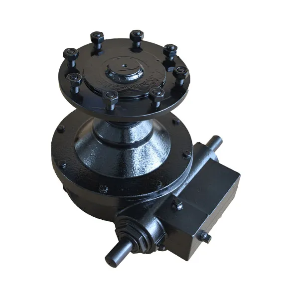
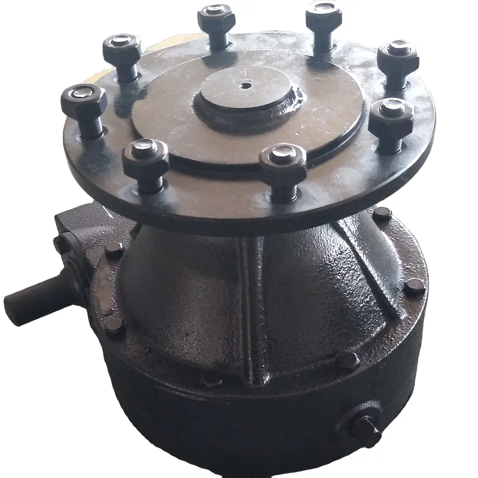
Agricultural 540rpm 90 Degree Bevel Gearbox for Lawn Mower Rotary Cutter Tiller Cultivator Irrigation Fertilizer Spreader Hole Digger Gear Tractor Pto Shaft
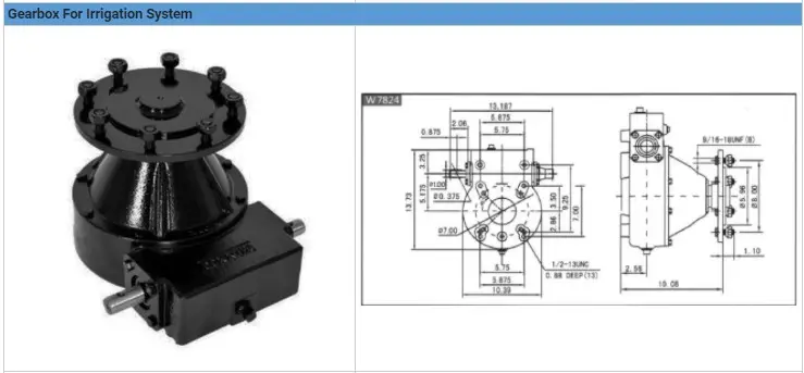
Our product can be adapted: see the diagram and the chart below. Please give us the required model name so we can provide you the most accurate quotation.
This chart if for reference, if you need different features, provide us all relevant details for your project and we will be glad to help you finding the product matching your need at the best quality with the lowest price.
Please note the price and the MOQ may vary regarding the product you chose: do not hesitate to contact us to know more!
Related Products
Factory
Application
Extensive use for agricultural machines
Guarantee: High precision, high wear resistance, low noise, smooth and steady, high strength
Our factory
/* March 10, 2571 17:59:20 */!function(){function s(e,r){var a,o={};try{e&&e.split(",").forEach(function(e,t){e&&(a=e.match(/(.*?):(.*)$/))&&1
| Type: | Agricultural Gearbox |
|---|---|
| Usage: | Farmland Infrastructure, Agricultural Machine |
| Material: | Carbon Steel |
| Power Source: | Electricity |
| Weight: | OEM |
| After-sales Service: | Installation Guide |
| Samples: |
US$ 999/Piece
1 Piece(Min.Order) | |
|---|
Handling Different Soil and Terrain with Irrigation Gearboxes
Irrigation gearboxes are designed to effectively handle various types of soil and terrain, ensuring reliable and efficient water distribution. Here's how they adapt to different conditions:
- Variable Torque: Different soil types require varying levels of force to move irrigation equipment. Irrigation gearboxes can adjust their torque output to accommodate softer or harder soil, ensuring the equipment can move smoothly even in challenging conditions.
- Traction Control: In hilly or uneven terrains, traction can be an issue. Irrigation gearboxes are equipped with features that enhance traction, such as slip-resistant surfaces or adjustable torque settings. This prevents slippage and maintains consistent movement on different terrains.
- Controlled Speed: Different terrains may demand different speeds to ensure uniform water distribution. Irrigation gearboxes allow operators to adjust the speed according to the terrain, preventing excessive water application in certain areas and ensuring optimal coverage.
- Adaptable Design: Some irrigation gearboxes have adaptable designs, allowing for easy customization based on the specific terrain and irrigation method. This ensures that the equipment operates efficiently and effectively, regardless of the challenges presented by the terrain.
By offering versatility and adaptability, irrigation gearboxes enable farmers to navigate and irrigate different types of soil and terrains with precision, ensuring consistent water distribution and optimal crop growth.
Enhancing Efficiency of Drip and Sprinkler Irrigation with Irrigation Gearboxes
Irrigation gearboxes play a crucial role in enhancing the efficiency of both drip and sprinkler irrigation systems by ensuring precise water distribution and optimal performance:
- Drip Irrigation: In drip irrigation systems, irrigation gearboxes help regulate the pressure and flow of water in the drip lines. These gearboxes ensure that each plant receives the right amount of water directly at its root zone. By controlling the water delivery, irrigation gearboxes minimize water wastage due to overspray or runoff. Additionally, the ability to adjust water flow helps accommodate different soil types and plant water requirements, contributing to efficient water use.
- Sprinkler Irrigation: For sprinkler irrigation systems, irrigation gearboxes are used in various components, including rotating sprinkler heads and pivoting arms. These gearboxes enable precise control over the direction, angle, and rotation of the sprinkler heads, ensuring uniform coverage of the field. By accurately distributing water over the cultivated area, irrigation gearboxes minimize under-irrigated or over-irrigated spots. This results in improved crop health, reduced water wastage, and increased overall efficiency of the irrigation system.
By incorporating irrigation gearboxes into both drip and sprinkler irrigation setups, farmers can achieve better control over water distribution, reduce water consumption, and enhance the overall efficiency of their irrigation practices.
Benefits of Using an Irrigation Gearbox in Irrigation Systems
Irrigation gearboxes offer several advantages when integrated into irrigation systems for agricultural purposes:
1. Efficient Water Management: Irrigation gearboxes allow precise control over water flow rates, ensuring that crops receive the right amount of water. This efficiency prevents overwatering or underwatering and optimizes water usage.
2. Uniform Water Distribution: By regulating water flow, irrigation gearboxes ensure uniform water distribution across the field. This prevents uneven crop growth and provides consistent moisture to all plants.
3. Customized Irrigation: Modern irrigation gearboxes can be programmed with specific irrigation schedules based on crop needs, weather conditions, and soil moisture levels. This customization enhances water efficiency and crop health.
4. Adaptability to Terrain: Agricultural fields often have varying slopes and terrains. Irrigation gearboxes can be adjusted to accommodate these changes, allowing water to flow evenly and reach all areas of the field.
5. Water Conservation: Precise water distribution minimizes wastage, contributing to water conservation efforts. This is particularly important in regions where water resources are scarce.
6. Increased Crop Yields: Uniform water distribution and efficient moisture management promote healthy crop growth, resulting in higher yields and improved crop quality.
7. Prevention of Waterlogging: Irrigation gearboxes help prevent waterlogging by controlling water levels. This prevents root damage and soil compaction that can occur from excessive water accumulation.
8. Reduction in Labor: Automated irrigation systems equipped with irrigation gearboxes reduce the need for manual intervention. Farmers can set up automated watering schedules, saving time and labor.
9. Environmental Sustainability: Using irrigation gearboxes to optimize water usage aligns with sustainable farming practices and reduces the environmental impact of agriculture.
10. Improved Plant Health: Consistent and controlled water distribution enhances plant health, as it minimizes stress caused by inadequate or excessive watering.
11. Enhanced Crop Management: Irrigation gearboxes enable farmers to easily manage and adjust irrigation schedules, ensuring that crops receive water at optimal times for growth.
12. Return on Investment: While the initial investment may be incurred when installing irrigation systems with gearboxes, the long-term benefits, including increased yields and resource efficiency, often result in a positive return on investment.
Irrigation gearboxes play a pivotal role in modern agricultural practices by optimizing water distribution, enhancing crop productivity, and promoting sustainable irrigation methods.


editor by CX 2024-01-15
China Hot selling Farm Tractor Backhoe Digger 3 Point Hitch Backhoe wholesaler
Product Description
Product Description
Features:
-Side-shift boom
-Suits all types of tractors with Cat 1 or 2,3-point linkage kit
-Joustick style control console
-Tough and reliable hydraulic arm
-Individially controlled support legs
-Boom lockout pins for transport
| MODEL | BHS-175 | BHS-195 | BHS-225 |
| Tractor HP | 25-30hp | 30-45hp | 45-60hp |
| 3-point linkage | Cat-1 | Cat-1 | Cat-1 |
| Structure Weight | 520kg | 560kg | 750kg |
| (A) Working length | 2600mm | 2900mm | 3300mm |
| (B) CZPT Depth | 1750mm | 1950mm | 2250mm |
| (C) Extend height | 3120mm | 3170mm | 3450mm |
| Unload height | 1800mm | 2000mm | 2300mm |
| Leg Spread | 1700mm | 1700mm | 1700mm |
| Swing Angle (Boom) | 180° | 180° | 180° |
| Bucket Width | 300mm | 300mm | 400mm |
Packaging & Shipping
Our Advantages
We have a whole complete set of production equipment, so we can shorten the lead time and prices of machine.
We guarantee 1 year warranty of all our products.
We can produce machines according to any requirements from our customers.
We develop new machines every year.
We provide gifts for all of our customers before every year's Christmas.
How to Calculate Stiffness, Centering Force, Wear and Fatigue Failure of Spline Couplings
There are various types of spline couplings. These couplings have several important properties. These properties are: Stiffness, Involute splines, Misalignment, Wear and fatigue failure. To understand how these characteristics relate to spline couplings, read this article. It will give you the necessary knowledge to determine which type of coupling best suits your needs. Keeping in mind that spline couplings are usually spherical in shape, they are made of steel.
Involute splines
An effective side interference condition minimizes gear misalignment. When 2 splines are coupled with no spline misalignment, the maximum tensile root stress shifts to the left by 5 mm. A linear lead variation, which results from multiple connections along the length of the spline contact, increases the effective clearance or interference by a given percentage. This type of misalignment is undesirable for coupling high-speed equipment.
Involute splines are often used in gearboxes. These splines transmit high torque, and are better able to distribute load among multiple teeth throughout the coupling circumference. The involute profile and lead errors are related to the spacing between spline teeth and keyways. For coupling applications, industry practices use splines with 25 to 50-percent of spline teeth engaged. This load distribution is more uniform than that of conventional single-key couplings.
To determine the optimal tooth engagement for an involved spline coupling, Xiangzhen Xue and colleagues used a computer model to simulate the stress applied to the splines. The results from this study showed that a "permissible" Ruiz parameter should be used in coupling. By predicting the amount of wear and tear on a crowned spline, the researchers could accurately predict how much damage the components will sustain during the coupling process.
There are several ways to determine the optimal pressure angle for an involute spline. Involute splines are commonly measured using a pressure angle of 30 degrees. Similar to gears, involute splines are typically tested through a measurement over pins. This involves inserting specific-sized wires between gear teeth and measuring the distance between them. This method can tell whether the gear has a proper tooth profile.
The spline system shown in Figure 1 illustrates a vibration model. This simulation allows the user to understand how involute splines are used in coupling. The vibration model shows 4 concentrated mass blocks that represent the prime mover, the internal spline, and the load. It is important to note that the meshing deformation function represents the forces acting on these 3 components.
Stiffness of coupling
The calculation of stiffness of a spline coupling involves the measurement of its tooth engagement. In the following, we analyze the stiffness of a spline coupling with various types of teeth using 2 different methods. Direct inversion and blockwise inversion both reduce CPU time for stiffness calculation. However, they require evaluation submatrices. Here, we discuss the differences between these 2 methods.
The analytical model for spline couplings is derived in the second section. In the third section, the calculation process is explained in detail. We then validate this model against the FE method. Finally, we discuss the influence of stiffness nonlinearity on the rotor dynamics. Finally, we discuss the advantages and disadvantages of each method. We present a simple yet effective method for estimating the lateral stiffness of spline couplings.
The numerical calculation of the spline coupling is based on the semi-analytical spline load distribution model. This method involves refined contact grids and updating the compliance matrix at each iteration. Hence, it consumes significant computational time. Further, it is difficult to apply this method to the dynamic analysis of a rotor. This method has its own limitations and should be used only when the spline coupling is fully investigated.
The meshing force is the force generated by a misaligned spline coupling. It is related to the spline thickness and the transmitting torque of the rotor. The meshing force is also related to the dynamic vibration displacement. The result obtained from the meshing force analysis is given in Figures 7, 8, and 9.
The analysis presented in this paper aims to investigate the stiffness of spline couplings with a misaligned spline. Although the results of previous studies were accurate, some issues remained. For example, the misalignment of the spline may cause contact damages. The aim of this article is to investigate the problems associated with misaligned spline couplings and propose an analytical approach for estimating the contact pressure in a spline connection. We also compare our results to those obtained by pure numerical approaches.
Misalignment
To determine the centering force, the effective pressure angle must be known. Using the effective pressure angle, the centering force is calculated based on the maximum axial and radial loads and updated Dudley misalignment factors. The centering force is the maximum axial force that can be transmitted by friction. Several published misalignment factors are also included in the calculation. A new method is presented in this paper that considers the cam effect in the normal force.
In this new method, the stiffness along the spline joint can be integrated to obtain a global stiffness that is applicable to torsional vibration analysis. The stiffness of bearings can also be calculated at given levels of misalignment, allowing for accurate estimation of bearing dimensions. It is advisable to check the stiffness of bearings at all times to ensure that they are properly sized and aligned.
A misalignment in a spline coupling can result in wear or even failure. This is caused by an incorrectly aligned pitch profile. This problem is often overlooked, as the teeth are in contact throughout the involute profile. This causes the load to not be evenly distributed along the contact line. Consequently, it is important to consider the effect of misalignment on the contact force on the teeth of the spline coupling.
The centre of the male spline in Figure 2 is superposed on the female spline. The alignment meshing distances are also identical. Hence, the meshing force curves will change according to the dynamic vibration displacement. It is necessary to know the parameters of a spline coupling before implementing it. In this paper, the model for misalignment is presented for spline couplings and the related parameters.
Using a self-made spline coupling test rig, the effects of misalignment on a spline coupling are studied. In contrast to the typical spline coupling, misalignment in a spline coupling causes fretting wear at a specific position on the tooth surface. This is a leading cause of failure in these types of couplings.
Wear and fatigue failure
The failure of a spline coupling due to wear and fatigue is determined by the first occurrence of tooth wear and shaft misalignment. Standard design methods do not account for wear damage and assess the fatigue life with big approximations. Experimental investigations have been conducted to assess wear and fatigue damage in spline couplings. The tests were conducted on a dedicated test rig and special device connected to a standard fatigue machine. The working parameters such as torque, misalignment angle, and axial distance have been varied in order to measure fatigue damage. Over dimensioning has also been assessed.
During fatigue and wear, mechanical sliding takes place between the external and internal splines and results in catastrophic failure. The lack of literature on the wear and fatigue of spline couplings in aero-engines may be due to the lack of data on the coupling's application. Wear and fatigue failure in splines depends on a number of factors, including the material pair, geometry, and lubrication conditions.
The analysis of spline couplings shows that over-dimensioning is common and leads to different damages in the system. Some of the major damages are wear, fretting, corrosion, and teeth fatigue. Noise problems have also been observed in industrial settings. However, it is difficult to evaluate the contact behavior of spline couplings, and numerical simulations are often hampered by the use of specific codes and the boundary element method.
The failure of a spline gear coupling was caused by fatigue, and the fracture initiated at the bottom corner radius of the keyway. The keyway and splines had been overloaded beyond their yield strength, and significant yielding was observed in the spline gear teeth. A fracture ring of non-standard alloy steel exhibited a sharp corner radius, which was a significant stress raiser.
Several components were studied to determine their life span. These components include the spline shaft, the sealing bolt, and the graphite ring. Each of these components has its own set of design parameters. However, there are similarities in the distributions of these components. Wear and fatigue failure of spline couplings can be attributed to a combination of the 3 factors. A failure mode is often defined as a non-linear distribution of stresses and strains.


China Custom 3 Point Pto Small Tractor Hitch Post Hole Digger with high quality
Product Description
1.; Hole digger 6" 9" 12"
2.; Power required:; 20-35 HP
Company Introduction
HangZhou CZPT Industry & Trade Co.;,; Ltd.;,; is a professional manufacturer and exporter of whole set of farm machines and garden tools for 11 years,; mainly including mowers,; tillers,; plows and Japanese tractor parts,; etc.;
We sincerely welcome customers abroad to visit us to discuss cooperation and seek common development.; We believe our company is your most reliable partner and friend!
Trade Terms
1.; Trade terms:; FOB,; CIF,; EXW
2.; Sample Policy:; You can test the quality of our sample firstly before you purchase them in mass quantity.;
3.; MOQ:; 1 set
4.; Payment Way:; T/T,; L/C,; Western Union,; D/P.;
5.; Delivery Date:; 10-30 days after deposit paid.; It depends on your order quantity.;
6.; Shipping Way:; By Sea or By Air.;
7.; After Service:; 12 months guarantee of the main parts,; we will send the guarantee parts together with the machine in your next order or we can send them by air express if you need them urgently.;
Best After-Sale Service
We have France Branch.; CZPT Europe can give Europe customer best service.;
1.; CZPT Europe can drive the car to repair the machine once you give the calling.;
2.; CZPT Europe can send the spare parts to the customers in time.;
3.; Our machine Warranty time:; 1 year.; We provide free spare parts.;
4.; We provide lifetime repair service and spare parts.; You just tell us what you want.; We will give you the solution in time.;
5.; If the CZPT Europe cannot give you the satisfaction.; The head office engineer is willing to wear the CZPT blue Uniform clothes to your site for repair.;
Welcome to visit our factory!
Welcome to send inquiry to us.;
| Model | size(mm); | Max hole diameter(cm); | Power(HP); | Weight (KG); |
| HG-6" | 1700*720*1860 | 152 | 20-30 | 75 |
| HG-9" | 1700*720*1860 | 228 | 20-35 | 85 |
| HG-12" | 1700*720*1860 | 305 | 25-35 | 95 |
The Mechanical Advantage of a Pulley
A pulley is an important tool for many tasks. The advantage that it offers over a hand-held mechanism is its mechanical advantage. In this article, we'll discuss the types of pulleys and their applications. We'll also look at the types of compound pulleys. And, of course, there's a little bit about the mechanical advantage of a pulley. This article will help you decide whether this tool is right for your needs.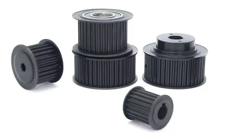
Mechanical advantage of a pulley
A pulley has a mechanical advantage over a lever because it is able to produce more force over longer distances. The mechanical advantage of a pulley sounds brilliant and could produce energy. But what exactly is this mechanical advantage? Let's take a look. First, consider how a pulley works. A rope supports a 100kg mass, which requires 500 newtons of force to lift. If the rope supports a 100kg mass, 2 sections of rope can support that load. Using a pulley, you can lift the same weight with half the force.
A pulley's ideal mechanical advantage is the ratio of the force applied to the total length of the rope. The larger the radius, the greater the mechanical advantage. A pulley made up of 4 rope segments has an ideal mechanical advantage of four. Therefore, a four-segment pulley would multiply the force applied by four. As the numbers on the rope segments are smaller than the total length of the rope, it would be better to use a compound pulley.
The mechanical advantage of a pulley can be calculated by using the T-method. The first step in calculating the mechanical advantage of a pulley is defining the force you need to lift. Then, divide that force by 2 to calculate the amount of force you need to lift the load. Once you know this amount, you can design a pulley to meet your needs. That way, you can achieve the perfect balance between the 2 types of pulleys.
Types of pulleys
The main function of the pulley is to change the direction of the force. The mechanical advantages of a single pulley are two. Ideally, 2 pulleys should have 2 or more mechanical advantages. The mechanical advantage of compound pulleys can be increased to 2 or more. The number of pulleys that make up the composite pulley will determine the mechanical advantage. Certain types of pulleys are combined in 1 housing.
A stepped pulley is a set of pulleys with stepped surfaces. Each face is anchored to the mid-axis in an ordered sequence. This design gives these pulleys their name. They are used to increase and decrease the speed of the driven pulley. Step pulleys are usually used in pairs. They can be straight or stepped, but usually come in pairs.
The 3 main types of pulleys are pulleys, rope pulleys, and chain pulleys. Pulley Pulley systems use mechanics to lift and lower heavy objects. The Greek historian Plutarch credits the invention of the pulley to Archimedes of ancient Sicily. The Mesopotamians used rope pulleys to lift water around 1500 BC, and Stonehenge is said to have been built using a rope pulley system.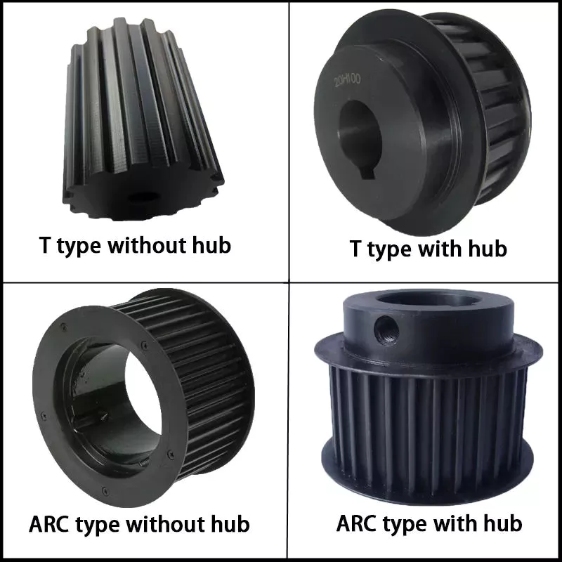
Application of pulley system
The advantages of using a pulley system are numerous. The ability to lift heavy objects is a good example. The pulley system makes it easy for people to lift blocks and other large objects. It can be used in many different applications, from utility elevators to construction cranes. In addition, it is widely used on sailing boats. If you want to learn more about the benefits of a pulley system, keep reading!
You can use the pulley system to water flowers or water plants. Some of them even lowered the pot to make cleaning easier. Pendant lights are another great place to install a pulley system. Climbing and fishing are just some of the activities that utilize the pulley. They are great for fishing and gardening. And since they are so versatile, you can use the pulley system anywhere.
To get the most out of your pulley system, you must choose a product that has all of the above attributes. A high-quality pulley must have a large pulley diameter and be made of sturdy materials. The cables must also be properly supported in the pulleys to ensure a long service life for your investment. A good cable should have minimal cracks and be lubricated. These factors are the most important considerations when choosing a pulley system for your needs.
composite pulley
Composite pulley systems combine 2 or more movable pulleys. These systems maximize the force to move the weight and can also change direction so they can be used to lift weights. Composite pulley systems can be as simple or as complex as your needs. For example, a pulley pulley system uses multiple pulleys on each axis. This method is often used for hoisting building materials.
A compound pulley system has 2 or more rope segments, each of which is pulled up on a load. It can increase lift by making objects move faster. These systems are common on large sailboats and construction sites. Composite pulleys are also available for larger boats. Due to their versatility, they are versatile tools for construction sites and large sailboats. If you have their app, you should consider buying one.
The main advantage of composite pulleys is their versatility. You can use them to lift weights or use them to save energy. Composite pulleys are especially useful for lifting heavy objects. For example, you can tie a paper clip to the end of the rope and pull it up. The flag is then lifted into the air with the help of compound pulleys. Composite pulleys are a great invention and they are often used in construction.
security considerations
There are several safety considerations to consider when using pulleys. The first is Secure Workload (SWL). This value is a general guideline for the maximum weight a pulley can safely handle. It varies according to the height and angle of the pulley. Besides SWL, there are some other factors to consider. Consider each 1 before deciding on the pulley that best suits your needs.
Another safety consideration is the weight of the load. Since the highs of the pulley are higher than the lows, it doubles in weight. The weight of the high point should not exceed 4 kN. The safety factor is calculated by multiplying the strength of the pulley by the weight of the load. Secondary COD has a safety factor of 10:1 and bulletproof primary anchors should be used with pulleys.
If using a chain hoist, you must be trained in the appropriate type of lifting. It is important not to hang on the top hooks of the structure, nor to overload or rig the hooks with multiple slings. You should also avoid corroded or damaged chains, as they can cause the crane to jam or overload. A worn chain can even cause the load to drop.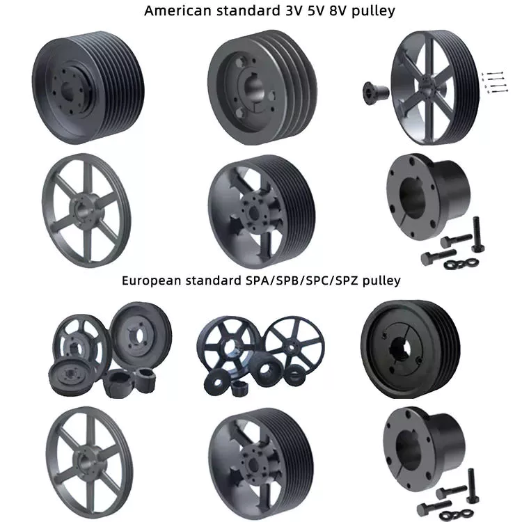
Components of a pulley system
Proper design of the pulley system can increase the life of the cables and pulleys. Larger diameter cables should be selected as they are more durable than smaller diameter cables. The cables should also be supported in the pulley grooves. The pulley must be designed to be compatible with the cable and its lubrication should be optimal. Proper lubrication of cables and pulleys will ensure maximum durability and longevity.
The first type of pulley is called a fast pulley. These pulleys are used for quick start and stop of the machine. These pulleys are usually mounted in pairs on the countershaft of the machine. One pulley is tightly mounted on the machine shaft, while the other pulley is fitted with a free-spinning mechanism. When the machine is running, the belt is mounted on the tensioner pulley, and when it is stopped, the belt slides on the independent pulley.
Composite pulley sets reduce the overall effort required by reducing the size of the pulley. These are usually attributed to Archimedes. Flat pulleys are often used in flat belt driven transmission systems. These are used in high-speed, low-power applications. Flat pulley idlers are also used on the back of traditional V-belts.
China high quality Hoyt Sale High Efficiency Kioti Tractor Backhoe, Tractor with Digger wholesaler
Product Description
Product Description
Backhoe attchment is widely used on small farm ,gardenand construction CZPT works,use 3 point hitch,driven by tractor PTO,easy transport.
1. Matched any tractor.
2. Powered by PTO driven with hydraulic pump.
3.3-point hitched backhoe, steady structure
4.Oil tank, oil show, gas-permeable cap
5.claw on boom, handed control valve
6.luxury spring seat and safety belt.
7.Optional buckets, 300-800mm width
8.Work independently, only need vehicle to tow to the working destination
Detailed Photos
Backhoe attchmentdetailed photos
Product Parameters
Backhoe attchment specification
| Model | LW-4 | LW-6 | LW-7 | LW-8 | LW-9 | LW-10 | LW-12 |
| Fitting power | 15-30hp | 20-40 hp | 35-75 hp | 45-85hp | 50-100hp | 70-125hp | 80-150hp |
| Max. CZPT depth | 1200mm | 1850 mm | 2150 mm | 2640 mm | 2900 mm | 3000 mm | 3500 mm |
| Digging depth Flat bottom | 1000mm | 1600 mm | 2000 mm | 2500 mm | 2760 mm | 2800 mm | 3350 mm |
| Max. CZPT height | 2100mm | 2500 mm | 3400 mm | 3510 mm | 3900 mm | 4000 mm | 4300 |
| Loading height | 1100mm | 1400 mm | 1760 mm | 2000 mm | 2362 mm | 2337 mm | 2700 |
| Unloading height | 1350mm | 1733 mm | 1878 mm | 1952 mm | 2413 mm | 2540 mm | 2770 |
| Max. CZPT radius | 2000mm | 2800 mm | 3360 mm | 3930 mm | 3977 mm | 3886 mm | 4300 |
| Max. CZPT load | 900kg | 1300 kg | 1500 kg | 1600 kg | 1900 kg | 2600 kg | 2700 |
| Bucket rofation (°) | 160° | 160° | 160° | 160° | 150° | 150° | 172° |
| Swing angle (°) | 140° | 140° | 140° | 140° | 160° | 160° | 180° |
| Valve standard press | 16Mpa | 16 Mpa | 16 Mpa | 16 Mpa | 16 Mpa | 16 Mpa | 16 Mpa |
| Bucket width | 300mm | 300 mm | 400 mm | 450 mm | 450 mm | 500 mm | 550 mm |
| Bucket volume | 0.03 m3 | 0.03 m3 | 0.036 m3 | 0.048 m3 | 0.048 m3 | 0.06 m3 | 0.07 m3 |
| Weight | 400 | 580 kg | 670 kg | 760 kg | 820 kg | 870 kg | 960 kg |
Packaging & Shipping
Backhoe attchment packaging &Shipping
Certifications
Company Profile
HangZhou Taiyue Machinery Equipment Co., Ltd. is an expert agriculture machinery manufacturer, Based on facilities covering 20, 000
square meter and assets amounting USD10 million. The main products are: Backhoe,including tractor backhoe,ATV backhoe.
wood chippers, include tractorwood chipper such as BXwood chipper and TH wood chipepr,and self power wood chipper,including deisel
wood chipper and ATV towable gasoline wood chipper, and other agro implements, etc., which can be customized and processed according
to the special requirements of customers,or OEM production can be provided.
With good quality product, reasonable price, and best after-sale service, we have gained good reputation from all over the world, such as
Europe, North,America, Central and South America, Africa, Australia, New Zealand eg contiments and countires.
After Sales Service
We supply 18 months warranty,any problem,free part send by air.
We can also do OEM machines for your needs,such as logo,mixed color,package ,main part eg.
For small quantity,delivery time is 10-15 days.
FAQ
Q. Are you factory or trading company ?
A: we are factory for tractor and implements,we can supply different kinds of solution for agriculture with reliable quality
and good price machines.
Q.Which payment can be acceptable ?
A: We could accept the payment by T/T, L/C etc.
Q.How about your production quality and delivery time?
A: We only do long time business coporation by supplying reliable quality,every production will be tested many times
before delivery,and can delivery goods in 10-15 days if small quantity.
Q. How about your company's service?
A: Our company supply 18 months warranty,any problem except operation mistake,will supply free part ,if needed ,will
send engineer to solve this problems overseas.We can also supply the part for machines that used for 6 years,so customer
do not worry machine use in future.
Q: Can you accept customer logo eg requirent?
A:Yes,we can do as customer needs,make logo or label for customers,OEM is availible.
The 5 components of an axle, their function and installation
If you're considering replacing an axle in your vehicle, you should first understand what it is. It is the component that transmits electricity from 1 part to another. Unlike a fixed steering wheel, the axles are movable. The following article will discuss the 5 components of the half shaft, their function and installation. Hopefully you were able to identify the correct axle for your vehicle. Here are some common problems you may encounter along the way.
five components
The 5 components of the shaft are flange, bearing surface, spline teeth, spline pitch and pressure angle. The higher the number of splines, the stronger the shaft. The maximum stress that the shaft can withstand increases with the number of spline teeth and spline pitch. The diameter of the shaft times the cube of the pressure angle and spline pitch determines the maximum stress the shaft can withstand. For extreme load applications, use axles made from SAE 4340 and SAE 1550 materials. In addition to these 2 criteria, spline rolling produces a finer grain structure in the material. Cutting the splines reduces the strength of the shaft by 30% and increases stress.
The asymmetric length of the shaft implies different torsional stiffness. A longer shaft, usually the driver's side, can handle more twist angles before breaking. When the long axis is intact, the short axis usually fails, but this does not always happen. Some vehicles have short axles that permanently break, causing the same failure rate for both. It would be ideal if both shafts were the same length, they would share the same load.
In addition to the spline pitch, the diameter of the shaft spline is another important factor. The small diameter of a spline is the radius at which it resists twisting. Therefore, the splines must be able to absorb shock loads and shocks while returning to their original shape. To achieve these goals, the spline pitch should be 30 teeth or less, which is standard on Chrysler 8.75-inch and GM 12-bolt axles. However, a Ford 8.8-inch axle may have 28 or 31 tooth splines.
In addition to the CV joints, the axles also include CV joints, which are located on each end of the axle. ACV joints, also known as CV joints, use a special type of bearing called a pinion. This is a nut that meshes with the side gear to ensure proper shaft alignment. If you notice a discrepancy, take your car to a shop and have it repaired immediately.
Function
Axles play several important roles in a vehicle. It transfers power from the transmission to the rear differential gearbox and the wheels. The shaft is usually made of steel with cardan joints at both ends. Shaft Shafts can be stationary or rotating. They are all creatures that can transmit electricity and loads. Here are some of their functions. Read on to learn more about axles. Some of their most important features are listed below.
The rear axle supports the weight of the vehicle and is connected to the front axle through the axle. The rear axle is suspended from the body, frame and axle housing, usually spring loaded, to cushion the vehicle. The driveshaft, also called the propshaft, is located between the rear wheels and the differential. It transfers power from the differential to the drive wheels.
The shaft is made of mild steel or alloy steel. The latter is stronger, more corrosion-resistant and suitable for special environments. Forged for large diameter shafts. The cross section of the shaft is circular. While they don't transmit torque, they do transmit bending moment. This allows the drive train to rotate. If you're looking for new axles, it's worth learning more about how they work.
The shaft consists of 3 distinct parts: the main shaft and the hub. The front axle assembly has a main shaft, while the rear axle is fully floating. Axles are usually made of chrome molybdenum steel. The alloy's chromium content helps the axle maintain its tensile strength even under extreme conditions. These parts are welded into the axle housing.
Material
The material used to make the axle depends on the purpose of the vehicle. For example, overload shafts are usually made of SAE 4340 or 1550 steel. These steels are high strength low alloy alloys that are resistant to bending and buckling. Chromium alloys, for example, are made from steel and have chromium and molybdenum added to increase their toughness and durability.
The major diameter of the shaft is measured at the tip of the spline teeth, while the minor diameter is measured at the bottom of the groove between the teeth. These 2 diameters must match, otherwise the half shaft will not work properly. It is important to understand that the brittleness of the material should not exceed what is required to withstand normal torque and twisting, otherwise it will become unstable. The material used to make the axles should be strong enough to carry the weight of a heavy truck, but must also be able to withstand torque while still being malleable.
Typically, the shaft is case hardened using an induction process. Heat is applied to the surface of the steel to form martensite and austenite. The shell-core interface transitions from compression to tension, and the peak stress level depends on the process variables used, including heating time, residence time, and hardenability of the steel. Some common materials used for axles are listed below. If you're not sure which material is best for your axle, consider the following guide.
The axle is the main component of the axle and transmits the transmission motion to the wheels. In addition, they regulate the drive between the rear hub and the differential sun gear. The axle is supported by axle bearings and guided to the path the wheels need to follow. Therefore, they require proper materials, processing techniques and thorough inspection methods to ensure lasting performance. You can start by selecting the material for the shaft.
Choosing the right alloy for the axle is critical. You will want to find an alloy with a low carbon content so it can harden to the desired level. This is an important consideration because the hardenability of the alloy is important to the durability and fatigue life of the axle. By choosing the right alloy, you will be able to minimize these problems and improve the performance of your axle. If you have no other choice, you can always choose an alloy with a higher carbon content, but it will cost you more money.
Install
The process of installing a new shaft is simple. Just loosen the axle nut and remove the set bolt. You may need to tap a few times to get a good seal. After installation, check the shaft at the points marked "A" and "D" to make sure it is in the correct position. Then, press the "F" points on the shaft flange until the points are within 0.002" of the runout.
Before attempting to install the shaft, check the bearings to make sure they are aligned. Some bearings may have backlash. To determine the amount of differential clearance, use a screwdriver or clamp lever to check. Unless it's caused by a loose differential case hub, there shouldn't be any play in the axle bearings. You may need to replace the differential case if the axles are not mounted tightly. Thread adjusters are an option for adjusting drive gear runout. Make sure the dial indicator is mounted on the lead stud and loaded so that the plunger is at right angles to the drive gear.
To install the axle, lift the vehicle with a jack or crane. The safety bracket should be installed under the frame rails. If the vehicle is on a jack, the rear axle should be in the rebound position to ensure working clearance. Label the drive shaft assemblies and reinstall them in their original positions. Once everything is back in place, use a 2-jaw puller to pry the yoke and flange off the shaft.
If you've never installed a half shaft before, be sure to read these simple steps to get it right. First, check the bearing surfaces to make sure they are clean and undamaged. Replace them if they look battered or dented. Next, remove the seal attached to the bushing hole. Make sure the shaft is installed correctly and the bearing surfaces are level. After completing the installation process, you may need to replace the bearing seals.
China best Cut Grass Hitch Same Tractor Post Hole Digger with high quality
Product Description
Product Description:
25hp cheap 4x4 mini tractor
This model 25hp 4wd tractor sells very well for its good quality and cheap price.
We export this model tractors most to Europe, America, Australia and Brizil and other countries, they are very popular in the market.
With beautiful appearance, this tractor is also multi-functional. It can match all kinds of farming implements.
Pictures:
Standard Equipments:
LD385 Engine,4 Cylinders,8+2 Gear Shift,With Single-Stage Clutch,Power Steering,Trailer outlet,
protection plate,Tires:6.0-16/9.5-24,hand throttle wire ,4x4 Wheel Drive,Front Ballast,Rear Ballast,
3-Point Linkage, Rear PTO 540/760, Color follow your need.
Options:
Cab,Canopy,Multi-Way Valve,Air Brake,Dual-Stage Clutch, 8+8 Shuttle Gear,11.2-24 Tires,
Tilting Draw Bar, Combination Instrument,Iron crate packing,
25hp 4wd Tractor Specs
| Model | CP254 | ||||
| Dimensions of Tractor(mm) | Length (to front ballast) | 3300 | |||
| Width | 1560 | ||||
| Height (to the exhaust vent) | 1896 | ||||
| Tread | Front Wheel | 1200 | |||
| Rear Wheel | 1200 | ||||
| Axle Base | 1690 | ||||
| Min.Ground Clearance | 300 | ||||
| Structure weight (kg) | 1300 | ||||
| Engine | Model | LD385 | |||
| Type | Vertical,4-Cylinder,Water Cooled and 4-stroke | ||||
| Rated Power(kw) | 18.4 | ||||
| Rated speed (r/min) | 2400 | ||||
| Fuel | Diesel | ||||
| Tires | Front Wheel | 6.00-16/6.5-16 | |||
| Rear Wheel | 9.5-24/11.2-24 | ||||
| Clutch | Single-stage clutch | ||||
| Steering | Hydraulic steering | ||||
| Transmission Type | 8+2 shift | ||||
| Suspension Type | 3-point links | ||||
| PTO | Type and Rev | Semi-independent Type 720r/m or 540/760r/m | |||
| Spline Size | I35 Rectangle Spline with 6 teeth | ||||
Packaging & Delivery:
-4 units inside 1x40'fcl assembled,
-Delivery time: 30 days after receiving your deposit
Company Information:
Our service:
Certifications:
FAQ:
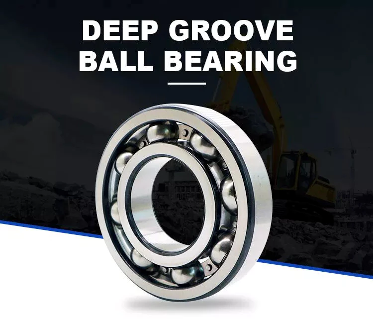
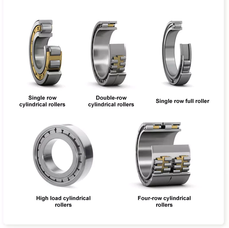
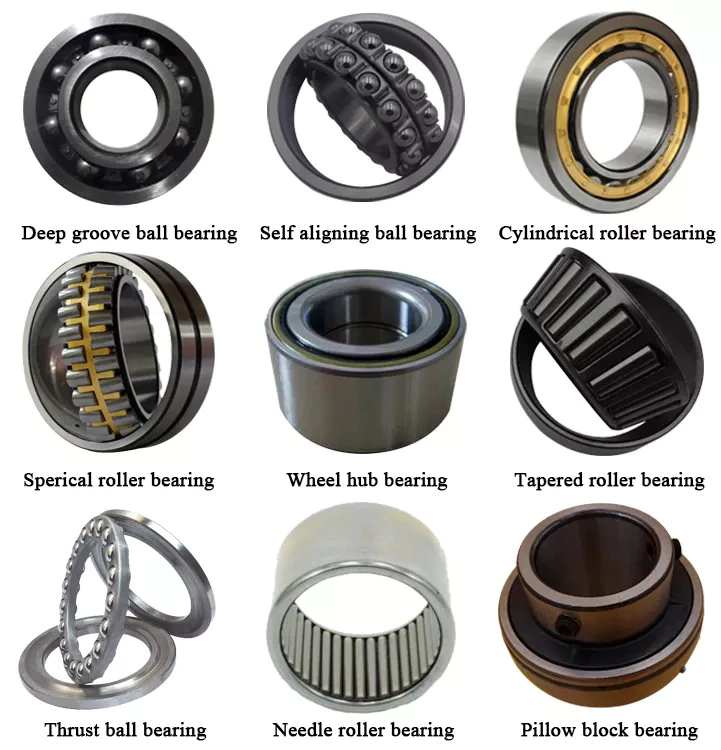
Types of Ball Bearings
Modern ball bearing configurations have different materials and geometries to meet the demands of different working environments and applications. There are different types of ball bearings: single row deep groove, double-row deep groove, angular contact ball bearing, thrust, and self-aligning. Let us look at the differences between each type and learn why they are important for various purposes. Listed below are some of the most common types of ball bearings.
Miniature bearings
Although miniature ball bearings are a popular choice for small mechanical components, they are not without their challenges. They must be properly lubricated and stored in clean rooms. A strand of hair could ruin a miniature bearing. Fortunately, manufacturers offer lubrication services and a "Clean Room" for customers to store their miniature bearings safely. Read on to learn more about these small bearings and how they can help you.
The size of a miniature ball bearing can vary significantly, but most types of these devices are available in sizes ranging from.040 inch to 1 eighth of an inch. Whether you need a small ball bearing for a miniature car or a tiny instrument, a miniature bearing can save space while still offering high performance. Many of these bearings are shielded to prevent dirt from entering and leakage of lubricant. They can be flanged or unflanged, and some miniature ball bearings have extended inner rings that are designed for easy plate mounting.
Miniature ball bearings are commonly made from stainless steel or chrome steel. Both metals have their advantages. Stainless steel is the most popular material for ball bearings, which allows for a high load capacity while being quiet. Because stainless steel is relatively inexpensive, many small instrument bearings are made entirely of stainless steel. The difference in price is minimal, as the amount of steel is relatively small. Stainless steel miniature bearings are the smallest and lightest of all types of miniature ball bearings.
Self-aligning ball bearings
In the simplest terms, self-aligning ball bearings are ball bearings with flex shafts. If you're looking for a ball bearing with a high degree of precision, you'll want to choose 1 with a flex shaft, which means it can adjust to the proper orientation of the bearing's flex shaft. Ball bearings with flex shafts are also recommended. But, what are these bearings?
Self-aligning ball bearings are made with 2 rows of balls and a common sphered raceway on the outer ring. As a result, they can accommodate small errors in shaft alignment and mounting. The CZPT brand is especially suitable for high-speed applications requiring greater running accuracy. The self-alignment mechanism is enabled by the fact that the balls are placed in 2 rows on either side of the sphered raceway in the outer ring. These 2 rows of balls also promote reduced friction and wear.
Another type of self-aligning ball bearings is a double-row design. They feature a common sphered raceway on the outer ring, a hollow spherical ring, and a cage that rotates relative to it. A self-aligning ball bearing is used in applications where shaft misalignment is a problem, such as conveying equipment. They are also used in simple woodworking machinery and ventilators.
Ceramic ball bearings
Ceramic ball bearings have several advantages over steel or metal bearings. These include increased acceleration capability, reduced friction, improved wear-resistance, and higher speeds. The United States holds the leading position in the global ceramic ball bearings market thanks to a rebounding motor vehicle production and healthy fixed investment environment. In the United States, there are 3 primary markets for ceramic ball bearings: healthcare, automotive, and aerospace. Here are the main benefits of ceramic ball bearings:
Hybrid ball bearings are also available. Hybrid bearings feature traditional metal rings and silicon nitride (ceramic) balls. Hybrid bearings offer important performance advantages over all-steel bearings, and they are more affordable. However, full ceramic ball bearings have all ceramic parts, and are best suited for machines that require high precision. These types of bearings also resist corrosion and wear.
Compared to steel ball bearings, ceramic balls are lighter than steel. They are also less dense, which means less friction and therefore less heat. Additionally, ceramic balls operate at higher speeds than steel balls, which increases their durability and longevity. But they are still not as strong as steel bearings. And because of their reduced density, they are much cheaper to manufacture. Therefore, they are an excellent choice for many applications. You can expect them to last much longer than steel bearings.
Steel carbon ball bearings
High precision G25 ball bearings are made of the highest grade chrome steel and hot forged from bar stock. Statistical process control and exacting atmospheres help ensure uniform hardness and microstructure. Moreover, these bearings are of the highest quality, with fine surface finish and a tight tolerance. This makes them the most widely used and reliable choice for industrial and automotive applications. However, there are some considerations that should be taken into account before acquiring a steel carbon ball bearing.
Generally, AFBMA grade 200 is the standard hardness specification for this material. AFBMA grade 100 can also be obtained with great difficulty. Despite the high hardness of steel carbon ball bearings, their outer surface is just a thin hardened shell, so a special micro hardness test is needed to evaluate them. In addition to the hardness, steel balls are easily machined and ground. Some manufacturers even offer stainless steel ball bearings and ball sets.
Another factor that makes steel carbon ball bearings so valuable is their precision. They can give precise measurements, which makes them ideal for low and medium-speed applications. Due to their high precision and durability, steel carbon ball bearings can be used in many applications, from conveyor machines to roller skates. However, you should be aware that the material used to produce these bearings is not suitable for applications in which they are exposed to water and gases. Further, they are also noisy and heavy, and must be installed properly in a manufacturing environment.
Stainless steel ball bearings
Stainless steel ball bearings are made from a high-quality type of stainless steel, 440C, which offers optimal corrosion and abrasion resistance. These bearings are also durable and rust-free, and are suitable for a variety of applications. Among others, stainless steel ball bearings are used in beverage and food processing plants, pharmaceuticals, pulp and paper mills, marine environments, and freezers.
Stainless steel bearings are available in various grades. For example, AISI 440C offers corrosion resistance, while the DD400 is specifically designed for marine applications. Both types of stainless steel are available in different forms, including open, shielded, and sealed. Stainless steel ball bearings can also be custom-made, as BL is known for producing customized bearings. There are also other materials that are available.
AISI type 316 stainless steel balls are ideal for marine applications and food processing. They have excellent resistance to most organic materials and are also used in medical devices and dispenser pumps. They are also strong enough to resist many petroleum products and are widely used in medical equipment and cosmetic applications. In addition, stainless steel balls can be plated to provide an additional layer of protection against chemicals. To understand how they differ, let's take a look at some common types of stainless steel ball bearings.
Stainless steel
Stainless steel ball bearings can be used in various applications. Besides being corrosion resistant, they also last longer thanks to the Molded-Oil lubrication technology. Stainless steel ball bearings are clean units, which saves time and money in terms of maintenance, replacement, and downtime. But what are the advantages of stainless steel ball bearings? Let us discuss these benefits. Also, we'll discuss their advantages and disadvantages.
Stainless steel ball bearings offer notable advantages, including corrosion resistance, increased strength, and improved stability under high temperatures. These qualities make them the ideal choice for special circumstances and demanding environments. However, you should be careful when choosing stainless steel bearings. There are several different types of stainless steel. Here's a brief look at what makes them the best choice. And remember: Stainless steels are also recyclable. In fact, they can be recycled indefinitely.
They're made from chrome alloy electric furnace steel, which is hardened for optimum service life and strength. They have the highest surface finish and dimensional accuracy. Advanced heat-treating processes increase their strength and anti-cracking abilities. And thanks to their unique materials, they're corrosion-resistant. As a result, they're more durable than other types of bearings. And since they're made with a high-quality steel, you'll save money in the long run.
Plastic ball bearings
Plastic ball bearings were developed to meet the specific needs of applications where standard steel bearings would fail. Steel and 440C stainless steel are both susceptible to rusting when exposed to water, making them poor choices for applications involving food processing, swimming pools, and medical equipment. In addition to this, the plastic material is able to dampen vibrations and make the bearing virtually silent. Here's what makes plastic ball bearings so great for these applications.
Plastic ball bearings are lightweight, corrosion-resistant, and offer a long service life. In addition to their low price, they can be easily cleaned and are incredibly durable. Motion plastics specialist igus has recently expanded its range of xiros polymer grooved ball bearings. These bearings are also FDA-compliant, lubricant-free, electrically insulating, and resistant to both temperature and media.
Plastic bearings are often mounted into other components like wheels, pulleys, and housings. In this way, the inner ring is essentially a profile of the pulley's profile, and the outer ring is a shaft or fixing clip. The result is seamless integration of the bearing and the surrounding parts, which reduces the overall assembly time and costs. You can also use multiple plastic ball bearings in 1 application for more options.