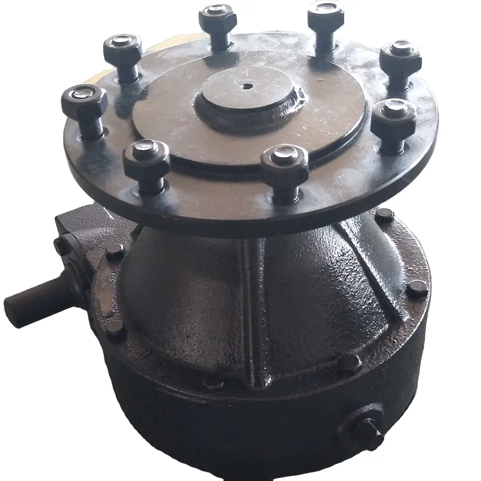
Product Description
Agricultural 540rpm 90 Degree Bevel Gearbox for Lawn Mower Rotary Cutter Tiller Cultivator Irrigation Fertilizer Spreader Hole Digger Gear Tractor Pto Shaft
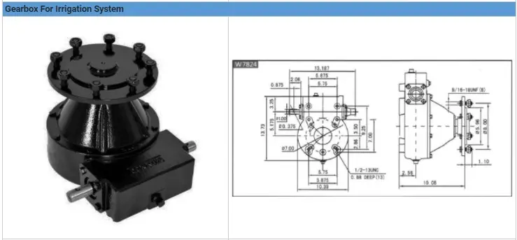
Our product can be adapted: see the diagram and the chart below. Please give us the required model name so we can provide you the most accurate quotation.
This chart if for reference, if you need different features, provide us all relevant details for your project and we will be glad to help you finding the product matching your need at the best quality with the lowest price.
Please note the price and the MOQ may vary regarding the product you chose: do not hesitate to contact us to know more!
Related Products
Factory
Application
Extensive use for agricultural machines
Guarantee: High precision, high wear resistance, low noise, smooth and steady, high strength
Our factory
/* March 10, 2571 17:59:20 */!function(){function s(e,r){var a,o={};try{e&&e.split(",").forEach(function(e,t){e&&(a=e.match(/(.*?):(.*)$/))&&1
| Type: | Agricultural Gearbox |
|---|---|
| Usage: | Farmland Infrastructure, Agricultural Machine |
| Material: | Carbon Steel |
| Power Source: | Electricity |
| Weight: | OEM |
| After-sales Service: | Installation Guide |
| Samples: |
US$ 999/Piece
1 Piece(Min.Order) | |
|---|
Handling Different Soil and Terrain with Irrigation Gearboxes
Irrigation gearboxes are designed to effectively handle various types of soil and terrain, ensuring reliable and efficient water distribution. Here's how they adapt to different conditions:
- Variable Torque: Different soil types require varying levels of force to move irrigation equipment. Irrigation gearboxes can adjust their torque output to accommodate softer or harder soil, ensuring the equipment can move smoothly even in challenging conditions.
- Traction Control: In hilly or uneven terrains, traction can be an issue. Irrigation gearboxes are equipped with features that enhance traction, such as slip-resistant surfaces or adjustable torque settings. This prevents slippage and maintains consistent movement on different terrains.
- Controlled Speed: Different terrains may demand different speeds to ensure uniform water distribution. Irrigation gearboxes allow operators to adjust the speed according to the terrain, preventing excessive water application in certain areas and ensuring optimal coverage.
- Adaptable Design: Some irrigation gearboxes have adaptable designs, allowing for easy customization based on the specific terrain and irrigation method. This ensures that the equipment operates efficiently and effectively, regardless of the challenges presented by the terrain.
By offering versatility and adaptability, irrigation gearboxes enable farmers to navigate and irrigate different types of soil and terrains with precision, ensuring consistent water distribution and optimal crop growth.
Enhancing Efficiency of Drip and Sprinkler Irrigation with Irrigation Gearboxes
Irrigation gearboxes play a crucial role in enhancing the efficiency of both drip and sprinkler irrigation systems by ensuring precise water distribution and optimal performance:
- Drip Irrigation: In drip irrigation systems, irrigation gearboxes help regulate the pressure and flow of water in the drip lines. These gearboxes ensure that each plant receives the right amount of water directly at its root zone. By controlling the water delivery, irrigation gearboxes minimize water wastage due to overspray or runoff. Additionally, the ability to adjust water flow helps accommodate different soil types and plant water requirements, contributing to efficient water use.
- Sprinkler Irrigation: For sprinkler irrigation systems, irrigation gearboxes are used in various components, including rotating sprinkler heads and pivoting arms. These gearboxes enable precise control over the direction, angle, and rotation of the sprinkler heads, ensuring uniform coverage of the field. By accurately distributing water over the cultivated area, irrigation gearboxes minimize under-irrigated or over-irrigated spots. This results in improved crop health, reduced water wastage, and increased overall efficiency of the irrigation system.
By incorporating irrigation gearboxes into both drip and sprinkler irrigation setups, farmers can achieve better control over water distribution, reduce water consumption, and enhance the overall efficiency of their irrigation practices.
Benefits of Using an Irrigation Gearbox in Irrigation Systems
Irrigation gearboxes offer several advantages when integrated into irrigation systems for agricultural purposes:
1. Efficient Water Management: Irrigation gearboxes allow precise control over water flow rates, ensuring that crops receive the right amount of water. This efficiency prevents overwatering or underwatering and optimizes water usage.
2. Uniform Water Distribution: By regulating water flow, irrigation gearboxes ensure uniform water distribution across the field. This prevents uneven crop growth and provides consistent moisture to all plants.
3. Customized Irrigation: Modern irrigation gearboxes can be programmed with specific irrigation schedules based on crop needs, weather conditions, and soil moisture levels. This customization enhances water efficiency and crop health.
4. Adaptability to Terrain: Agricultural fields often have varying slopes and terrains. Irrigation gearboxes can be adjusted to accommodate these changes, allowing water to flow evenly and reach all areas of the field.
5. Water Conservation: Precise water distribution minimizes wastage, contributing to water conservation efforts. This is particularly important in regions where water resources are scarce.
6. Increased Crop Yields: Uniform water distribution and efficient moisture management promote healthy crop growth, resulting in higher yields and improved crop quality.
7. Prevention of Waterlogging: Irrigation gearboxes help prevent waterlogging by controlling water levels. This prevents root damage and soil compaction that can occur from excessive water accumulation.
8. Reduction in Labor: Automated irrigation systems equipped with irrigation gearboxes reduce the need for manual intervention. Farmers can set up automated watering schedules, saving time and labor.
9. Environmental Sustainability: Using irrigation gearboxes to optimize water usage aligns with sustainable farming practices and reduces the environmental impact of agriculture.
10. Improved Plant Health: Consistent and controlled water distribution enhances plant health, as it minimizes stress caused by inadequate or excessive watering.
11. Enhanced Crop Management: Irrigation gearboxes enable farmers to easily manage and adjust irrigation schedules, ensuring that crops receive water at optimal times for growth.
12. Return on Investment: While the initial investment may be incurred when installing irrigation systems with gearboxes, the long-term benefits, including increased yields and resource efficiency, often result in a positive return on investment.
Irrigation gearboxes play a pivotal role in modern agricultural practices by optimizing water distribution, enhancing crop productivity, and promoting sustainable irrigation methods.


editor by CX 2024-01-15
China Custom Farm Machine Pto Small Tractor Tiller Cuitivator Power near me supplier
Product Description
Product Description:
| Product Name | Farm Machine PTO Small Tractor Tiller Cuitivator Power |
| Model | RT-125 |
| Color | depend on customer's choice |
| Dimension(mm) | 1460*550*560 |
| Number of blades | 28 |
| Cutting Width | 125cm |
| Tilling depth | 8-12 |
| Power Required | 20-30HP |
*Transmission: chain driven.
*Graphite gearbox is made of casting iron. Material performance is better. Not easy broken.
*The suspension plate shape is not easy to deform.
*Chain device hand adjustable. More easy and reliable.
*Side protection plates are added CZPT the rear deflection. This device prevents the soil flying out.
*The tilling height can be adjustable.
*The structure is firm and stable.
Packing & Delivery
Packing Details : Packing, wooden box for the garden tiller ,1pcs/carton
Delivery Details : 25 days after order
Our service
Best After Sales Service:
We have France Branch. CZPT Europe can give Europe customer best service.
1. CZPT Europe can send you spare parts once you need them.
2. Our machine Warranty time: 14 months. We provide free spare parts.
3. We provide lifetime repair service and spare parts. You just tell us what you want. We will give you the solution in time.
4.If the CZPT Europe cannot give you the satisfaction. The head office engineer is willing to wear the CZPT blue Uniform clothes to your site for repair.
Our Purpose:
Quality first, best service, win-win!
Welcome to visit our factory !
Welcome to send inquiry to us !
FAQ&Contact
Q: Are you trading company or manufacturer ?
A: We are factory.
Factory Address: No2.Xihu (West Lake) Dis.ng Road,TiHangZhou District,HangZhou,ZheJiang ,China
Q: How long is your delivery time?
A: Generally it is 14 months
Contact with me below:
Ms Sky
HangZhou CZPT Industary and Trade Co.,Ltd
Tel:86~/8822 0571 -88166585 Fax:86~/8822 0571 -88166595
Website: cnlefa
The Functions of Splined Shaft Bearings
Splined shafts are the most common types of bearings for machine tools. They are made of a wide variety of materials, including metals and non-metals such as Delrin and nylon. They are often fabricated to reduce deflection. The tooth profile will become deformed with time, as the shaft is used over a long period of time. Splined shafts are available in a huge range of materials and lengths.
Functions
Splined shafts are used in a variety of applications and industries. They are an effective anti-rotational device, as well as a reliable means of transmitting torque. Other types of shafts are available, including key shafts, but splines are the most convenient for transmitting torque. The following article discusses the functions of splines and why they are a superior choice. Listed below are a few examples of applications and industries in which splines are used.
Splined shafts can be of several styles, depending on the application and mechanical system in question. The differences between splined shaft styles include the design of teeth, overall strength, transfer of rotational concentricity, sliding ability, and misalignment tolerance. Listed below are a few examples of splines, as well as some of their benefits. The difference between these styles is not mutually exclusive; instead, each style has a distinct set of pros and cons.
A splined shaft is a cylindrical shaft with teeth or ridges that correspond to a specific angular position. This allows a shaft to transfer torque while maintaining angular correspondence between tracks. A splined shaft is defined as a cylindrical member with several grooves cut into its circumference. These grooves are equally spaced around the shaft and form a series of projecting keys. These features give the shaft a rounded appearance and allow it to fit perfectly into a grooved cylindrical member.
While the most common applications of splines are for shortening or extending shafts, they can also be used to secure mechanical assemblies. An "involute spline" spline has a groove that is wider than its counterparts. The result is that a splined shaft will resist separation during operation. They are an ideal choice for applications where deflection is an issue.
A spline shaft's radial torsion load distribution is equally distributed, unless a bevel gear is used. The radial torsion load is evenly distributed and will not exert significant load concentration. If the spline couplings are not aligned correctly, the spline connection can fail quickly, causing significant fretting fatigue and wear. A couple of papers discuss this issue in more detail.
Types
There are many different types of splined shafts. Each type features an evenly spaced helix of grooves on its outer surface. These grooves are either parallel or involute. Their shape allows them to be paired with gears and interchange rotary and linear motion. Splines are often cold-rolled or cut. The latter has increased strength compared to cut spines. These types of shafts are commonly used in applications requiring high strength, accuracy, and smoothness.
Another difference between internal and external splined shafts lies in the manufacturing process. The former is made of wood, while the latter is made of steel or a metal alloy. The process of manufacturing splined shafts involves cutting furrows into the surface of the material. Both processes are expensive and require expert skill. The main advantage of splined shafts is their adaptability to a wide range of applications.
In general, splined shafts are used in machinery where the rotation is transferred to an internal splined member. This member can be a gear or some other rotary device. These types of shafts are often packaged together as a hub assembly. Cleaning and lubricating are essential to the life of these components. If you're using them on a daily basis, you'll want to make sure to regularly inspect them.
Crowned splines are usually involute. The teeth of these splines form a spiral pattern. They are used for smaller diameter shafts because they add strength. Involute splines are also used on instrument drives and valve shafts. Serration standards are found in the SAE. Both kinds of splines can also contain a ball bearing for high torque. The difference between the 2 types of splines is the number of teeth on the shaft.
Internal splines have many advantages over external ones. For example, an internal spline shaft can be made using a grinding wheel instead of a CNC machine. It also uses a more accurate and economical process. Furthermore, it allows for a shorter manufacturing cycle, which is essential when splining high-speed machines. In addition, it stabilizes the relative phase between the spline and thread.
Manufacturing methods
There are several methods used to fabricate a splined shaft. Key and splined shafts are constructed from 2 separate parts that are shaped in a synchronized manner to transfer torque uniformly. Hot rolling is 1 method, while cold rolling utilizes low temperatures to form metal. Both methods enhance mechanical properties, surface finishes, and precision. The advantage of cold rolling is its cost-effectiveness.
Cold forming is 1 method, as well as machining and assembling. Cold forming is a unique process that allows the spline to be shaped to the desired shape. The resulting shape provides maximum contact area and torsional strength. Standard splines are available in standard sizes, but custom lengths can also be ordered. CZPT offers various auxiliary equipment, such as mating sleeves and flanged bushings.
Cold forging is another method. This method produces long splined shafts that are used in automobile propellers. After the spline portion is cut out, it is worked on in a hobbing machine. Work hardening enhances the root strength of the splined portion. It can be used for bearings, gears, and other mechanical components. Listed below are the manufacturing methods for splined shafts.
Parallel splines are the simplest of the splined shaft manufacturing methods. Parallel splines are usually welded to shafts, while involute splines are made of metal or non-metals. Splines are available in a wide variety of lengths and materials. The process is usually accompanied by a process called milling. The workpiece rotates to produce the serrated surface.
Splines are internal or external grooves in a splined shaft. They work in combination with keyways to transfer torque. Male and female splines are used in gears. Female and male splines correspond to 1 another to ensure proper angular correspondence. Involute splines have more surface area and thus are stronger than external splines. Moreover, they help the shaft fit into a grooved cylindrical member without misalignment.
A variety of other methods of manufacturing a splined shaft can be used to produce a splined shaft. Spline shafts can be produced using broaching and shaping, 2 precision machining methods. Broaching uses a metal tool with successively larger teeth to remove metal and create ridges and holes in the surface of a material. However, this process is expensive and requires special expertise.
Applications
The splined shaft is a mechanical component with a helix-like shape formed by the equal spacing of grooves in a circular ring. The splines can either have parallel or involute sides. The splines minimize stress concentration in stationary joints and can be used in both rotary and linear motion. In some cases, splines are rolled rather than cut. The latter is more durable than cut splines and is often used in applications requiring high strength, accuracy, and smooth finish.
Splined shafts are commonly made of carbon steel. This alloy steel has a low carbon content, making it easy to work with. Carbon steel is a great choice for splines because it is malleable. Generally, high-quality carbon steel provides a consistent motion. Steel alloys are also available that contain nickel, chromium, copper, and other metals. If you're unsure of the right material for your application, you can consult a spline chart.
Splines are a versatile mechanical component. They are easy to cut and fit. Splines can be internal or external, with teeth positioned at equal intervals on both sides of the shaft. This allows the shaft to engage with the hub around the entire circumference of the hub. It also increases load capacity by creating a constant multiple-tooth point of contact with the hub. For this reason, they're used extensively in rotary and linear motion.
Splined shafts are used in a wide variety of industries. CZPT Inc. offers custom and standard splined shafts for a variety of applications. When choosing a splined shaft for a specific application, consider the surrounding mated components, torque requirements, and size requirements. These 3 factors will make it the ideal choice for your rotary equipment. And you'll be pleased with the end result!
There are many types of splines and their applications are endless. They transfer torque and angular misalignment between parts, and they also enable the axial rotation of assembled components. Therefore, splines are an essential component of machinery and are used in a wide range of applications. This type of shaft can be found in various types of machines, from household appliances to industrial machinery. So, the next time you're looking for a splined shaft, make sure you look for a splined one.


China Professional Rice Farming Machinery 3 Points Tractor Rotary Tiller Wholesale Price near me factory
Product Description
Product Description:;
| Product Name | Rice farming machinery 3 points tractor rotary tiller wholesale price |
| Model | RT-125 |
| Color | depend on customer's choice |
| Dimension(mm); | 1460*550*560 |
| Number of blades | 28 |
| Cutting Width | 125cm |
| Tilling depth | 8-12 |
| Power Required | 20-30HP |
*Transmission:; chain driven.;
*Graphite gearbox is made of casting iron.; Material performance is better.; Not easy broken.;
*The suspension plate shape is not easy to deform.;
*Chain device hand adjustable.; More easy and reliable.;
*Side protection plates are added CZPT the rear deflection.; This device prevents the soil flying out.;
*The tilling height can be adjustable.;
*The structure is firm and stable.;
Packing & Delivery
Packing Details :; Packing,; wooden box for the garden tiller ,;1pcs/carton
Delivery Details :; 25 days after order
Our service
Best After Sales Service:;
We have France Branch.; CZPT Europe can give Europe customer best service.;
1.; CZPT Europe can send you spare parts once you need them.;
2.; Our machine Warranty time:; 14 months.; We provide free spare parts.;
3.; We provide lifetime repair service and spare parts.; You just tell us what you want.; We will give you the solution in time.;
4.;If the CZPT Europe cannot give you the satisfaction.; The head office engineer is willing to wear the CZPT blue Uniform clothes to your site for repair.;
Our Purpose:;
Quality first,; best service,; win-win!
Welcome to visit our factory !
Welcome to send inquiry to us !
FAQ&Contact
Q:; Are you trading company or manufacturer ?
A:; We are factory.;
Factory Address:; No2.;Xihu (West Lake) Dis.ng Road,;TiHangZhou District,;HangZhou,;ZheJiang ,;China
Q:; How long is your delivery time?
A:; Generally it is 14 months
Contact with me below:;
Ms Sky
HangZhou CZPT Industary and Trade Co.;,;Ltd
Tel:;86~/8822 0571 -88166585 Fax:;86~/8822 0571 -88166595
Website:; cnlefa.;en.;made-in-china.;com
Worm Gear Motors
Worm gear motors are often preferred for quieter operation because of the smooth sliding motion of the worm shaft. Unlike gear motors with teeth, which may click as the worm turns, worm gear motors can be installed in a quiet area. In this article, we will talk about the CZPT whirling process and the various types of worms available. We'll also discuss the benefits of worm gear motors and worm wheel.
worm gear
In the case of a worm gear, the axial pitch of the ring pinion of the corresponding revolving worm is equal to the circular pitch of the mating revolving pinion of the worm gear. A worm with 1 start is known as a worm with a lead. This leads to a smaller worm wheel. Worms can work in tight spaces because of their small profile.
Generally, a worm gear has high efficiency, but there are a few disadvantages. Worm gears are not recommended for high-heat applications because of their high level of rubbing. A full-fluid lubricant film and the low wear level of the gear reduce friction and wear. Worm gears also have a lower wear rate than a standard gear. The worm shaft and worm gear is also more efficient than a standard gear.
The worm gear shaft is cradled within a self-aligning bearing block that is attached to the gearbox casing. The eccentric housing has radial bearings on both ends, enabling it to engage with the worm gear wheel. The drive is transferred to the worm gear shaft through bevel gears 13A, 1 fixed at the ends of the worm gear shaft and the other in the center of the cross-shaft.
worm wheel
In a worm gearbox, the pinion or worm gear is centered between a geared cylinder and a worm shaft. The worm gear shaft is supported at either end by a radial thrust bearing. A gearbox's cross-shaft is fixed to a suitable drive means and pivotally attached to the worm wheel. The input drive is transferred to the worm gear shaft 10 through bevel gears 13A, 1 of which is fixed to the end of the worm gear shaft and the other at the centre of the cross-shaft.
Worms and worm wheels are available in several materials. The worm wheel is made of bronze alloy, aluminum, or steel. Aluminum bronze worm wheels are a good choice for high-speed applications. Cast iron worm wheels are cheap and suitable for light loads. MC nylon worm wheels are highly wear-resistant and machinable. Aluminum bronze worm wheels are available and are good for applications with severe wear conditions.
When designing a worm wheel, it is vital to determine the correct lubricant for the worm shaft and a corresponding worm wheel. A suitable lubricant should have a kinematic viscosity of 300 mm2/s and be used for worm wheel sleeve bearings. The worm wheel and worm shaft should be properly lubricated to ensure their longevity.
Multi-start worms
A multi-start worm gear screw jack combines the benefits of multiple starts with linear output speeds. The multi-start worm shaft reduces the effects of single start worms and large ratio gears. Both types of worm gears have a reversible worm that can be reversed or stopped by hand, depending on the application. The worm gear's self-locking ability depends on the lead angle, pressure angle, and friction coefficient.
A single-start worm has a single thread running the length of its shaft. The worm advances 1 tooth per revolution. A multi-start worm has multiple threads in each of its threads. The gear reduction on a multi-start worm is equal to the number of teeth on the gear minus the number of starts on the worm shaft. In general, a multi-start worm has 2 or 3 threads.
Worm gears can be quieter than other types of gears because the worm shaft glides rather than clicking. This makes them an excellent choice for applications where noise is a concern. Worm gears can be made of softer material, making them more noise-tolerant. In addition, they can withstand shock loads. Compared to gears with toothed teeth, worm gears have a lower noise and vibration rate.
CZPT whirling process
The CZPT whirling process for worm shafts raises the bar for precision gear machining in small to medium production volumes. The CZPT whirling process reduces thread rolling, increases worm quality, and offers reduced cycle times. The CZPT LWN-90 whirling machine features a steel bed, programmable force tailstock, and five-axis interpolation for increased accuracy and quality.
Its 4,000-rpm, 5-kW whirling spindle produces worms and various types of screws. Its outer diameters are up to 2.5 inches, while its length is up to 20 inches. Its dry-cutting process uses a vortex tube to deliver chilled compressed air to the cutting point. Oil is also added to the mixture. The worm shafts produced are free of undercuts, reducing the amount of machining required.
Induction hardening is a process that takes advantage of the whirling process. The induction hardening process utilizes alternating current (AC) to cause eddy currents in metallic objects. The higher the frequency, the higher the surface temperature. The electrical frequency is monitored through sensors to prevent overheating. Induction heating is programmable so that only certain parts of the worm shaft will harden.
Common tangent at an arbitrary point on both surfaces of the worm wheel
A worm gear consists of 2 helical segments with a helix angle equal to 90 degrees. This shape allows the worm to rotate with more than 1 tooth per rotation. A worm's helix angle is usually close to 90 degrees and the body length is fairly long in the axial direction. A worm gear with a lead angle g has similar properties as a screw gear with a helix angle of 90 degrees.
The axial cross section of a worm gear is not conventionally trapezoidal. Instead, the linear part of the oblique side is replaced by cycloid curves. These curves have a common tangent near the pitch line. The worm wheel is then formed by gear cutting, resulting in a gear with 2 meshing surfaces. This worm gear can rotate at high speeds and still operate quietly.
A worm wheel with a cycloid pitch is a more efficient worm gear. It reduces friction between the worm and the gear, resulting in greater durability, improved operating efficiency, and reduced noise. This pitch line also helps the worm wheel engage more evenly and smoothly. Moreover, it prevents interference with their appearance. It also makes worm wheel and gear engagement smoother.
Calculation of worm shaft deflection
There are several methods for calculating worm shaft deflection, and each method has its own set of disadvantages. These commonly used methods provide good approximations but are inadequate for determining the actual worm shaft deflection. For example, these methods do not account for the geometric modifications to the worm, such as its helical winding of teeth. Furthermore, they overestimate the stiffening effect of the gearing. Hence, efficient thin worm shaft designs require other approaches.
Fortunately, several methods exist to determine the maximum worm shaft deflection. These methods use the finite element method, and include boundary conditions and parameter calculations. Here, we look at a couple of methods. The first method, DIN 3996, calculates the maximum worm shaft deflection based on the test results, while the second one, AGMA 6022, uses the root diameter of the worm as the equivalent bending diameter.
The second method focuses on the basic parameters of worm gearing. We'll take a closer look at each. We'll examine worm gearing teeth and the geometric factors that influence them. Commonly, the range of worm gearing teeth is 1 to four, but it can be as large as twelve. Choosing the teeth should depend on optimization requirements, including efficiency and weight. For example, if a worm gearing needs to be smaller than the previous model, then a small number of teeth will suffice.
China best Rotary Tiller 3-Point Hitch Tractor Cultivating Machine 3s Series Subsoiler near me supplier
Product Description
Rotary Tiller 3-Point Hitch Tractor Cultivating Machine 3s Series Subsoiler
Product Description
3S series of subsoiler is mainly suitable for subsoiling in the field of potato ,beans ,cotton and can break surface soil harden, loosen soil, retain water underground ,and clean stubble. It has advantages of adjustable depth ,wide range of applying ,convenient suspension and so on.
Specification
| Model | unit | 3S-1.0 | 3S-1.4 | 3S-1.8 | 3S-2.1 | 3S-2.6 |
| Working width | mm | 1000 | 1400 | 1800 | 2100 | 2600 |
| No. of plowbody | pcs | 5 | 7 | 9 | 11 | 13 |
| Working depth | mm | 100-240 | ||||
| Total weight | kg | 240 | 280 | 320 | 370 | 450 |
| Matched power | hp | 25-30 | 30-40 | 50-60 | 70-80 | 80-90 |
Product Material
Produce Euipment
Company Information
ESTABLISHED IN 2012.YUCHENF FRXIHU (WEST LAKE) DIS.S MACHINERY CO.LTD.IS A PROFESSIONAL AGRICULTURAL MACHINERY MANUFAC-TURER INTEGRATING RESEARCH,DEVELOPMENT,PRODUCTION,SALE AND SERVICE OF AGRICULTURAL MACHINERY.FRXIHU (WEST LAKE) DIS.S HAS ADVANCED MACHINING,WELDING,FORGING.SHAPING.HEAT TREATMNT PROCESSING TECHNOLOGY.
LOCATED HangZhou CITY SHANDON PROVINCE.FRXIHU (WEST LAKE) DIS.S COMPANY COVERS AN AREA OF 22000 SQUARE METERS,IN WHICH STHangZhouRD WORKSHOP FLOOR SPACE COVERS MORE THAN 6000 SAUARE METERS.THE COMPANY OWNS MORE THAN 60 EM-PLOYEES,ENGINEER AND QUYALITY CONTROL PERSONNEL.
OUR MAIN PRODUCTS INCLUDE DISC HARROW,DISC PLOUGH,CULTIVATOR,SHARE PLOW,FARM TRAILER.GRASS MOWER,SEEDER.HARVESTER.DISS BLADE,BREAK SHOVEL AND OTHER AGRO PARTS.ESPECIALLY IN HEAT TREATMENT OF THE BLADE,WE HAVE ACCUMULATED RICH EXPERIENCE.THE PRODUCTION OF BLADE WITH EXCELLENT TECHNOLOGY AND RELIABLE QUAL-ITY HAS WON THE CUSTOMER'S WIDELY RECOGNIZED.
WITH THE MARKET AND THE USER'S ACTUAL DEMAND,LEYUAN MACHINERY IS CONSTANTLY TRYING TO PROMOTE THE INTE-GRATION OF AGRICUL TURAL MACHINERY AND AGRICULTURAL ESTABLISHED IN 2012.YUCHENF FRXIHU (WEST LAKE) DIS.S MACHINERY CO.LTD.IS A PROFESSIONAL AGRICULTURAL ARTS.THE COMPANY BASED ON CHINA LOACAL MARKET AND EX-PORTED UNITED STATES,AUSTRALIA,MEXICO,THAILAND,PAKISTAN,INDODESIA,MOROCCO,NIGERIA,SOUTH AFRICA,SUDAN,ZheJiang AND OTHER COUNTRIES AND REGIONS.
Packaging & Shipping
FAQ:
Q1: Are you a factory or trading company?
We are a factory with self-supported import and export right.
Q2: How can I trust on your company?
We are a fully registered manufacture and exporting company by China Export Registration Authorities. Moreover, our products have been exporting to a number of countries including Swi tzerland, Russia, Spain, Netherlands, Australia, Peru, Thailand,Pakistan, Indonesia, Tanzania, Nigeria, South Africa, Sudan, Congo etc. The good faith,punctual, strict quality control and reasonable price, throughout s the pledge we to each customer.
Q3: Where is your factory located? How can I visit there?
Our factory is located in HangZhou City, ZheJiang Province, China. About 1 hour away from HangZhou Airport. AllI our clients are warmly welcomed to visit us!
Q4: How can I place an order from your website?
It is very easy. Once you find the implement you need on our website and place an inquiry against it, or, get to the inquiry section and leave us a message there with name, country and phone number, we will get in touch with you at the earliest. You can also e-mail us directly or join us on live chat for instantaneous answers.
Q5: How can I make the payment?
Payment is made via Telegraphic Transfer (T/T) through the bank against the Performa invoice. 40% as prepayment and the balance when the goods are ready for shipping.Irrevocable L/C at sight could be also accepted.
Q6: What' s the Payment terms?
FOB, the price of the implement without sea shipment costs.
Q7: At which port do you usually ship the good?
We usually ship goods via HangZhou, ZheJiang , HangZhou, ZheJiang port of China.
Q8. How about the Warranty ?
12 months warranty from the time of the goods arrive at destination.
Types of Ball Bearings
In their most basic form, Ball Bearings have 1 common feature - they are made of steel. The majority of these bearings are made of 52100 steel, which has 1 percent chromium and 1 percent carbon. The steel can be hardened by heat trea
tment. 440C stainless steel is used for rusting problems. A cage around the ball balls is traditionally made from thin steel. However, some bearings use molded plastic cages to save money and friction.
Single-row designs
Steel linear translation stages often use single-row designs for ball bearings. These types of bearings provide smooth linear travel and can withstand high loads. The material steel has a high modulus of elasticity and a high stiffness, as well as a lower thermal expansion than aluminum. For these reasons, steel is the material of choice for a ball bearing in a typical user environment. Single-row designs for ball bearings are also suitable for applications in humid or corrosive environments.
Single-row designs for ball bearings are available in a variety of sizes and are axially adjustable. They have a high radial capacity, but require relatively little space. Single-row deep groove ball bearings with snap rings are STN 02 4605 or R47, respectively. Bearings with snap rings are identified by a suffix such as NR. They may not have seals or shields installed.
These single-row angular contact ball bearings are capable of supporting axial and radial loads. In a two-raceway arrangement, the radial load on bearing A causes a radial load to act on bearing B. Both axial and radial forces are transmitted between single-row angular contact ball bearings, and the resulting internal force must be taken into account to calculate equivalent dynamic bearing loads P.
Single-row deep groove ball bearings are the most common type of ball bearings. These bearings are designed with only 1 row of rolling elements. The single-row design is simple and durable, which makes it ideal for high-speed applications. Single-row designs for ball bearings are also available in various bore sizes. They can also come in a variety of shapes and are non-separable. If you need a high-speed bearing, you may want to opt for a double-row design.
In addition to single-row designs for ball bearings, you can choose ceramic or steel ball bearings. Ceramic balls are considerably harder than steel balls, but they are not as hard as steel. Hence, ceramic bearings are stiffer than steel ball bearings, resulting in increased stress on the outer race groove and lower load capacity. This is a great benefit for those who need the bearings to be lightweight and strong.
The difference between single-row and double-row designs is in the way that the inner and outer ring are installed. A single-row design places the inner ring in an eccentric position relative to the outer ring. The 2 rings are in contact at 1 point, which causes a large gap in the bearing. The balls are then inserted through the gap. As a result, the balls are evenly distributed throughout the bearing, which forces the inner and outer rings to become concentric.
Deep-groove ball bearings are 1 of the most popular types of ball bearings. They are available in different designs, including snap-ring, seal and shield arrangements. The race diameter of a deep-groove ball bearing is close to the ball's diameter. These types of bearings are suited for heavy loads, and their axial and radial support are excellent. Their main drawback is that the contact angle cannot be adjusted to accommodate a wide range of relative loads.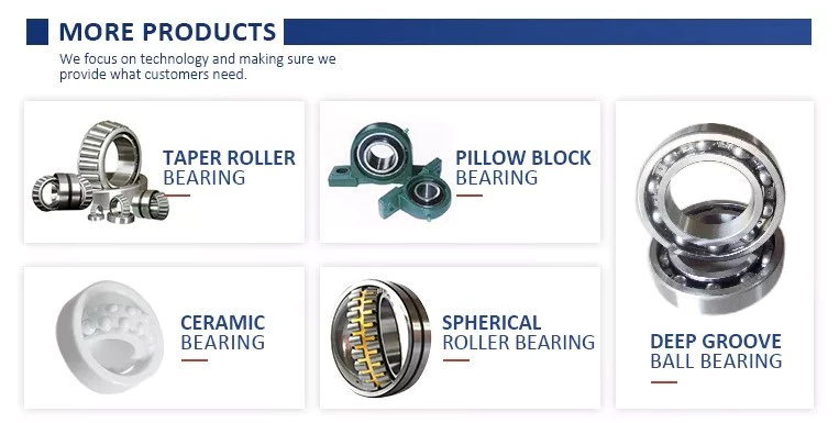
Ceramic hybrid ball bearings
Hybrid ball bearings with ceramic balls have numerous advantages. They feature improved kinematic behavior and require less lubrication. Consequently, they can reduce operating costs. Additionally, their low thermal expansion coefficient allows for smaller changes in contact angle and preload variations, and they can retain tolerances. Furthermore, ceramic hybrid ball bearings have significantly increased life spans compared to conventional steel-steel ball bearings, with up to 10 times the lifespan.
Although ceramic bearings can be used in automotive applications, many people believe that they're a poor choice for bicycle hubs. They don't reduce weight and only work well in high-rpm environments. As a result, many cyclists don't even bother with ceramic-based bearings. However, both Paul Lew and Alan are of the opinion that ceramic bearings are best suited for industrial or medical equipment applications. Furthermore, Paul and Alan believe that they are ideal for high-altitude drone motors.
Another advantage of ceramic hybrid ball bearings is that they use less friction than conventional steel-based balls. They are also more durable, requiring less lubrication than steel-based bearings. Furthermore, the lower friction and rolling resistance associated with ceramic-based ball bearings means that they can last 10 times longer than steel-based bearings. A ceramic-based hybrid ball bearing can be used for applications where speed and lubrication are critical.
Ceramic hybrid ball bearings feature both steel and silicon nitride balls. Silicon nitride balls have 50% more modulus of elasticity than steel balls and can improve accuracy and precision. Ceramic balls also have a smoother surface finish than steel balls, which reduces vibration and spindle deflection. These benefits result in increased speed and improved production quality. In addition to this, ceramic balls can also reduce the operating temperature, enhancing the work environment.
Hybrid bearings are a popular alternative to steel bearings. They have some benefits over traditional steel bearings, and are becoming a popular choice for engineered applications. Hybrid bearings are ideal for high speed machines. The material used to manufacture ceramic balls is a high-quality alloy, and is comparatively inexpensive. But you must understand that lubrication is still necessary for hybrid bearings. If you are not careful, you may end up wasting money.
These ball bearings can be used in many industries and applications, and they are widely compatible with most metals. The main advantage of hybrid ball bearings is that they are very durable. While steel balls tend to corrode and wear out, ceramic ball bearings can withstand these conditions while minimizing maintenance and replacement costs. The benefits of hybrid ball bearings are clear. So, consider switching to these newer types of ball bearings.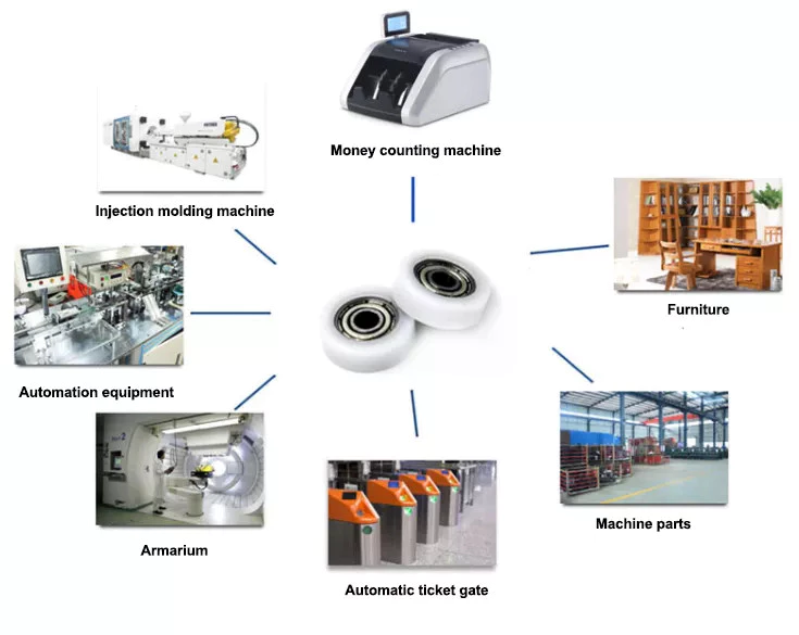
Self-aligning ball bearings
Self-aligning ball bearings are a good choice for many applications. They are a great alternative to traditional ball bearings, and they are ideal for rotating applications in which the shaft must move in several directions. They are also ideal for use in rotating parts where a tight tolerance is necessary. You can choose between 2 types: plain and flex shaft. Read on to find out which 1 will suit your needs.
Self-aligning ball bearings are designed with a higher axial load carrying capacity than single-row radial deep groove ball bearings. The amount of axial load carrying capacity is dependent upon the pressure angle. These bearings have a hollow raceway in the outer ring that allows the inner ring to pivot without friction. They are often used for high-speed applications. Because of their design, they are highly accurate.
Self-aligning ball bearings are radial bearings that feature 2 rows of balls in a spherical outer ring. They also feature 2 deep uninterrupted raceway grooves in the inner ring. Their unique features make them an excellent choice for applications where shaft deflection is a significant factor. Despite their small size, they have a high level of precision and can withstand heavy loads.
Self-aligning ball bearings can compensate for misalignment in shaft applications. The inner ring and ball assembly are positioned inside an outer ring containing a curved raceway. This spherical design allows the balls and cage to deflect and re-align around the bearing center. These bearings are also ideal for applications where shaft deflection is significant, such as in simple woodworking machinery.
Another type of self-aligning ball bearing uses a common concave outer race. Both balls and outer races automatically compensate for angular misalignment caused by machining, assembly, and deflections. Compared to spherical rollers, they have lower frictional losses than their spherical counterparts. Self-alignment ball bearings also have lower vibration levels compared to other types of bearings.
Self-aligning ball bearings operate in misaligned applications because their spherical outer raceway can accommodate misalignment. This design allows them to work in applications where shaft deflection or housing deformation is common. They are therefore more suitable for low to medium-sized loads. The only real drawback to self-aligning ball bearings is their price. If you need to purchase a self-aligning ball bearing for your next project, you can expect to pay around $1500.
China OEM High Quality Farm Use 3 Point Hitch Tractor Rotavator Rotary Tiller with CE (RT95) near me shop
Product Description
ROTARY TILLER--RT-95
| Mode | RT-85 | RT-95 | RT-105 | RT-115 | RT-125 | RT-135 |
| Dimension(mm) | 950*550*560 | 1050*550*560 | 1150*550*560 | 1250*550*560 | 1350*550*560 | 1450*550*560 |
| Working width(cm) | 85 | 95 | 105 | 115 | 125 | 135 |
| PTO Input speed(rpm) | 540r/min | 540r/min | 540r/min | 540r/min | 540r/min | 540r/min |
| Weight(Kg) | 110kg | 115kg | 125kg | 135kg | 145kg | 155kg |
| Number of blades | 16 | 16 | 20 | 24 | 28 | 32 |
| Tilling depth(cm) | 8-12 | 8-12 | 8-12 | 8-12 | 8-12 | 8-12 |
| Packing size(mm) | 1060*650*660 | 1160*650*660 | 1260*650*660 | 1360*650*660 | 1460*650*660 | 1560*650*660 |
| Power required | 15-25HP | 15-25HP | 15-25HP | 20-30HP | 20-30HP | 20-30HP |
PRODUCT ATTRIBUTE
1. Transmission: Chain driven.
2. Gravity gearbox is made of casting iron. Material performance is better. Not easy broken.
3. The suspension plate shape is not easy to deform.
4. Chain device hand adjustable. More easy and reliable.
5. Side protection plates are added CZPT the rear deflection. This device prevents the soil flying out.
6. The tilling height can be adjustable.
7. The structure is firm and stable.
----------------------
Company Profile
HangZhou CZPT Industry & Trade Co., Ltd., is a professional manufacturer and exporter of whole set of agriculture machines and garden tools. Our company was established since 2003 with Hanma Industry Company.
Our main products include rotovator, flail mower, finishing mower, CZPT mower, wood chipper, plow, cultivator, potato harvester/ planter and Japanese tractor parts, etc. Due to our super International quality standard and rapid & excellent after-sales service, CZPT machines are greatly popular in various markets around the world, and already reached to Europe, North America, South America, Australia, almost covers 80 countries in World.
LEFA always believe that we will take better farming life to you by top-quality laser cutting machine & CNC bending machine & professional paint-spraying & strong welding.
PROFESSIONAL PRODUCTION
1.Professional team with rich experience
2.Powerful factory strength with CE certification
3.Best after-sales service
Packing & Shipping
Packaging Detail: Iron pallet or wooden cases
Delivery Detail: By sea or By air
1. Waterproof packing with the international export standard by 20ft, 40ftcontainer.
Wooden Case or Iron Pallet.
2. The whole set of machines size are large as normal, so we will use Waterproof materials to pack
all of them. The motor, gear box or other easily damaged parts, we will put them into box.
We have a professional shipping department, they will try their best to save your container quantity.
Machine videos in YOUTOBE
EFDL SIDE MOWERS
EFGL SIDE MOWERS
FM FINISHING MOWERS
TM CZPT MOWERS
RT ROTARY TILLERS
https://youtu.be/d3H1-yXUImc AP-90 POTATO HARVESTER
https://youtu.be/AAkgnV_bY80 LF-PT32 POTATO PLANTER
https://youtu.be/66geQQOUTLY wood chipper BX-42
https://youtu.be/iIVOwCTCl_c HAY BALER
FAQ
Q1. How to buy 3 point rotary tiller?
Inquiry ---------> Quotation -------->Price reasonable ------->Check with specification ----->Proforma Invoice sent ------------>Payment made -------> Producing the items ------->Product shipment -----------> Customer confirm
Q2.How long is the delivery date for agriculture machinery cultivator?
A:In general, we can ship the goods within 30-45 days after receiving your payment. Of course, it also depends on your quantity.
Q3. How can I get to your factory to buy tractor cultivator?
A:We are located in HangZhou, only 1 hour's distance to ZheJiang or HangZhou. You can fly to ZheJiang /HangZhou/HangZhou Airport , the transportation is very convenient
Q4.Do you have stock for rotary tiller?
A:In general, we have some stock, while if you need a bulk order, we still need time to produce it. Of course, we will inform all details you before your payment.
Q5: What's your main products?
A: Our products are covered almost all farm machines and Japanese tractors parts, we can meet your any demands.
Q6. What is your terms of payment?
A: T/T, L/C, Paypal, Western Union
Synthesis of Epicyclic Gear Trains for Automotive Automatic Transmissions
In this article, we will discuss the synthesis of epicyclic gear trains for automotive automatic transmissions, their applications, and cost. After you have finished reading, you may want to do some research on the technology yourself. Here are some links to further reading on this topic. They also include an application in hybrid vehicle transmissions. Let's look at the basic concepts of epicyclic gear trains. They are highly efficient and are a promising alternative to conventional gearing systems.
Synthesis of epicyclic gear trains for automotive automatic transmissions
The main purpose of automotive automatic transmissions is to maintain engine-drive wheel balance. The kinematic structure of epicyclic gear trains (EGTs) is derived from graph representations of these gear trains. The synthesis process is based on an algorithm that generates admissible epicyclic gear trains with up to 10 links. This algorithm enables designers to design auto gear trains that have higher performance and better engine-drive wheel balance.
In this paper, we present a MATLAB optimization technique for determining the gear ratios of epicyclic transmission mechanisms. We also enumerate the number of teeth for all gears. Then, we estimate the overall velocity ratios of the obtained EGTs. Then, we analyze the feasibility of the proposed epicyclic gear trains for automotive automatic transmissions by comparing their structural characteristics.
A six-link epicyclic gear train is depicted in the following functional diagram. Each link is represented by a double-bicolor graph. The numbers on the graph represent the corresponding links. Each link has multiple joints. This makes it possible for a user to generate different configurations for each EGT. The numbers on the different graphs have different meanings, and the same applies to the double-bicolor figure.
In the next chapter of this article, we discuss the synthesis of epicyclic gear trains for automotive automatic transaxles. SAE International is an international organization of engineers and technical experts with core competencies in aerospace and automotive. Its charitable arm, the SAE Foundation, supports many programs and initiatives. These include the Collegiate Design Series and A World In Motion(r) and the SAE Foundation's A World in Motion(r) award.
Applications
The epicyclic gear system is a type of planetary gear train. It can achieve a great speed reduction in a small space. In cars, epicyclic gear trains are often used for the automatic transmission. These gear trains are also useful in hoists and pulley blocks. They have many applications in both mechanical and electrical engineering. They can be used for high-speed transmission and require less space than other types of gear trains.
The advantages of an epicyclic gear train include its compact structure, low weight, and high power density. However, they are not without disadvantages. Gear losses in epicyclic gear trains are a result of friction between gear tooth surfaces, churning of lubricating oil, and the friction between shaft support bearings and sprockets. This loss of power is called latent power, and previous research has demonstrated that this loss is tremendous.
The epicyclic gear train is commonly used for high-speed transmissions, but it also has a small footprint and is suitable for a variety of applications. It is used as differential gears in speed frames, to drive bobbins, and for the Roper positive let-off in looms. In addition, it is easy to fabricate, making it an excellent choice for a variety of industrial settings.
Another example of an epicyclic gear train is the planetary gear train. It consists of 2 gears with a ring in the middle and the sun gear in the outer ring. Each gear is mounted so that its center rotates around the ring of the other gear. The planet gear and sun gear are designed so that their pitch circles do not slip and are in sync. The planet gear has a point on the pitch circle that traces the epicycloid curve.
This gear system also offers a lower MTTR than other types of planetary gears. The main disadvantage of these gear sets is the large number of bearings they need to run. Moreover, planetary gears are more maintenance-intensive than parallel shaft gears. This makes them more difficult to monitor and repair. The MTTR is also lower compared to parallel shaft gears. They can also be a little off on their axis, causing them to misalign or lose their efficiency.
Another example of an epicyclic gear train is the differential gear box of an automobile. These gears are used in wrist watches, lathe machines, and automotives to transmit power. In addition, they are used in many other applications, including in aircrafts. They are quiet and durable, making them an excellent choice for many applications. They are used in transmission, textile machines, and even aerospace. A pitch point is the path between 2 teeth in a gear set. The axial pitch of 1 gear can be increased by increasing its base circle.
An epicyclic gear is also known as an involute gear. The number of teeth in each gear determines its rate of rotation. A 24-tooth sun gear produces an N-tooth planet gear with a ratio of 3/2. A 24-tooth sun gear equals a -3/2 planet gear ratio. Consequently, the epicyclic gear system provides high torque for driving wheels. However, this gear train is not widely used in vehicles.
Cost
The cost of epicyclic gearing is lower when they are tooled rather than manufactured on a normal N/C milling machine. The epicyclic carriers should be manufactured in a casting and tooled using a single-purpose machine that has multiple cutters to cut the material simultaneously. This approach is widely used for industrial applications and is particularly useful in the automotive sector. The benefits of a well-made epicyclic gear transmission are numerous.
An example of this is the planetary arrangement where the planets orbit the sun while rotating on its shaft. The resulting speed of each gear depends on the number of teeth and the speed of the carrier. Epicyclic gears can be tricky to calculate relative speeds, as they must figure out the relative speed of the sun and the planet. The fixed sun is not at zero RPM at mesh, so the relative speed must be calculated.
In order to determine the mesh power transmission, epicyclic gears must be designed to be able to "float." If the tangential load is too low, there will be less load sharing. An epicyclic gear must be able to allow "float." It should also allow for some tangential load and pitch-line velocities. The higher these factors, the more efficient the gear set will be.
An epicyclic gear train consists of 2 or more spur gears placed circumferentially. These gears are arranged so that the planet gear rolls inside the pitch circle of the fixed outer gear ring. This curve is called a hypocycloid. An epicyclic gear train with a planet engaging a sun gear is called a planetary gear train. The sun gear is fixed, while the planet gear is driven.
An epicyclic gear train contains several meshes. Each gear has a different number of meshes, which translates into RPM. The epicyclic gear can increase the load application frequency by translating input torque into the meshes. The epicyclic gear train consists of 3 gears, the sun, planet, and ring. The sun gear is the center gear, while the planets orbit the sun. The ring gear has several teeth, which increases the gear speed.
Another type of epicyclic gear is the planetary gearbox. This gear box has multiple toothed wheels rotating around a central shaft. Its low-profile design makes it a popular choice for space-constrained applications. This gearbox type is used in automatic transmissions. In addition, it is used for many industrial uses involving electric gear motors. The type of gearbox you use will depend on the speed and torque of the input and output shafts.
China best Hand Tiller Machine Agricole Aratro a Disco Tines Twist 3 Point Hitch Petrol Micro Rotary Tiller Garden Cultivator Tractor with Good quality
Product Description
|
Tiller Type |
BS2Q-65 |
BS2QD-38 |
BS2Q |
BS2QB |
|
Product Name |
Hand-held Gasoline Tiller |
Hand-held Gasoline Tiller |
Hand-held Gasoline Tiller |
Hand-held Gasoline Tiller |
|
Engine |
144FA single-cylinder gasoline air cooled gasoline engine |
144FA single-cylinder gasoline air cooled gasoline engine |
1E48F single-cylinder gasoline air cooled gasoline engine |
NP130 single-cylinder air-cooled gasoline engine |
|
Stroke |
2-stroke |
2-stroke |
2-stroke |
4-stroke |
|
Start Method |
hand pull |
hand pull |
hand pull |
hand pull |
|
Power/speed |
2.2kw/6500r/min |
2.2kw/6500r/min |
2.2kw/6500r/min |
2.2kw/3600r/min |
|
Fuel Oil |
90# gasoline and above pure gasoline |
90# gasoline and above pure gasoline |
93# gasoline and 2-stroke engine oil mixture, fuel-to-run ratio is 25:1 |
90# gasoline and above pure gasoline |
|
Fuel Tank Capacity(L) |
1.1 |
1.1 |
1.3 |
0.9 |
|
Power Oil Capacity(L) |
0.25 |
0.25 |
/ |
0.4 |
|
Clutch Way |
Automatic centrifugal |
Automatic centrifugal |
Automatic centrifugal |
Automatic centrifugal |
|
Reduction Ratio |
1:59 |
1:29 |
1:29 |
1:29 |
|
Gearbox Oil Capacity(L) |
0.3 |
0.2 |
0.2 |
0.2 |
|
Working Width(mm) |
650 |
380 |
300-650 |
300-650 |
|
Operating Hour Productivity(h/m)hm² |
0.04-0.06 |
0.04-0.06 |
0.04-0.06 |
0.04-0.06 |
How to Calculate the Diameter of a Worm Gear

In this article, we will discuss the characteristics of the Duplex, Single-throated, and Undercut worm gears and the analysis of worm shaft deflection. Besides that, we will explore how the diameter of a worm gear is calculated. If you have any doubt about the function of a worm gear, you can refer to the table below. Also, keep in mind that a worm gear has several important parameters which determine its working.
Duplex worm gear
A duplex worm gear set is distinguished by its ability to maintain precise angles and high gear ratios. The backlash of the gearing can be readjusted several times. The axial position of the worm shaft can be determined by adjusting screws on the housing cover. This feature allows for low backlash engagement of the worm tooth pitch with the worm gear. This feature is especially beneficial when backlash is a critical factor when selecting gears.
The standard worm gear shaft requires less lubrication than its dual counterpart. Worm gears are difficult to lubricate because they are sliding rather than rotating. They also have fewer moving parts and fewer points of failure. The disadvantage of a worm gear is that you cannot reverse the direction of power due to friction between the worm and the wheel. Because of this, they are best used in machines that operate at low speeds.
Worm wheels have teeth that form a helix. This helix produces axial thrust forces, depending on the hand of the helix and the direction of rotation. To handle these forces, the worms should be mounted securely using dowel pins, step shafts, and dowel pins. To prevent the worm from shifting, the worm wheel axis must be aligned with the center of the worm wheel's face width.
The backlash of the CZPT duplex worm gear is adjustable. By shifting the worm axially, the section of the worm with the desired tooth thickness is in contact with the wheel. As a result, the backlash is adjustable. Worm gears are an excellent choice for rotary tables, high-precision reversing applications, and ultra-low-backlash gearboxes. Axial shift backlash is a major advantage of duplex worm gears, and this feature translates into a simple and fast assembly process.
When choosing a gear set, the size and lubrication process will be crucial. If you're not careful, you might end up with a damaged gear or 1 with improper backlash. Luckily, there are some simple ways to maintain the proper tooth contact and backlash of your worm gears, ensuring long-term reliability and performance. As with any gear set, proper lubrication will ensure your worm gears last for years to come.
Single-throated worm gear
Worm gears mesh by sliding and rolling motions, but sliding contact dominates at high reduction ratios. Worm gears' efficiency is limited by the friction and heat generated during sliding, so lubrication is necessary to maintain optimal efficiency. The worm and gear are usually made of dissimilar metals, such as phosphor-bronze or hardened steel. MC nylon, a synthetic engineering plastic, is often used for the shaft.
Worm gears are highly efficient in transmission of power and are adaptable to various types of machinery and devices. Their low output speed and high torque make them a popular choice for power transmission. A single-throated worm gear is easy to assemble and lock. A double-throated worm gear requires 2 shafts, 1 for each worm gear. Both styles are efficient in high-torque applications.
Worm gears are widely used in power transmission applications because of their low speed and compact design. A numerical model was developed to calculate the quasi-static load sharing between gears and mating surfaces. The influence coefficient method allows fast computing of the deformation of the gear surface and local contact of the mating surfaces. The resultant analysis shows that a single-throated worm gear can reduce the amount of energy required to drive an electric motor.
In addition to the wear caused by friction, a worm wheel can experience additional wear. Because the worm wheel is softer than the worm, most of the wear occurs on the wheel. In fact, the number of teeth on a worm wheel should not match its thread count. A single-throated worm gear shaft can increase the efficiency of a machine by as much as 35%. In addition, it can lower the cost of running.
A worm gear is used when the diametrical pitch of the worm wheel and worm gear are the same. If the diametrical pitch of both gears is the same, the 2 worms will mesh properly. In addition, the worm wheel and worm will be attached to each other with a set screw. This screw is inserted into the hub and then secured with a locknut.
Undercut worm gear
Undercut worm gears have a cylindrical shaft, and their teeth are shaped in an evolution-like pattern. Worms are made of a hardened cemented metal, 16MnCr5. The number of gear teeth is determined by the pressure angle at the zero gearing correction. The teeth are convex in normal and centre-line sections. The diameter of the worm is determined by the worm's tangential profile, d1. Undercut worm gears are used when the number of teeth in the cylinder is large, and when the shaft is rigid enough to resist excessive load.
The center-line distance of the worm gears is the distance from the worm centre to the outer diameter. This distance affects the worm's deflection and its safety. Enter a specific value for the bearing distance. Then, the software proposes a range of suitable solutions based on the number of teeth and the module. The table of solutions contains various options, and the selected variant is transferred to the main calculation.
A pressure-angle-angle-compensated worm can be manufactured using single-pointed lathe tools or end mills. The worm's diameter and depth are influenced by the cutter used. In addition, the diameter of the grinding wheel determines the profile of the worm. If the worm is cut too deep, it will result in undercutting. Despite the undercutting risk, the design of worm gearing is flexible and allows considerable freedom.
The reduction ratio of a worm gear is massive. With only a little effort, the worm gear can significantly reduce speed and torque. In contrast, conventional gear sets need to make multiple reductions to get the same reduction level. Worm gears also have several disadvantages. Worm gears can't reverse the direction of power because the friction between the worm and the wheel makes this impossible. The worm gear can't reverse the direction of power, but the worm moves from 1 direction to another.
The process of undercutting is closely related to the profile of the worm. The worm's profile will vary depending on the worm diameter, lead angle, and grinding wheel diameter. The worm's profile will change if the generating process has removed material from the tooth base. A small undercut reduces tooth strength and reduces contact. For smaller gears, a minimum of 14-1/2degPA gears should be used.
Analysis of worm shaft deflection
To analyze the worm shaft deflection, we first derived its maximum deflection value. The deflection is calculated using the Euler-Bernoulli method and Timoshenko shear deformation. Then, we calculated the moment of inertia and the area of the transverse section using CAD software. In our analysis, we used the results of the test to compare the resulting parameters with the theoretical ones.
We can use the resulting centre-line distance and worm gear tooth profiles to calculate the required worm deflection. Using these values, we can use the worm gear deflection analysis to ensure the correct bearing size and worm gear teeth. Once we have these values, we can transfer them to the main calculation. Then, we can calculate the worm deflection and its safety. Then, we enter the values into the appropriate tables, and the resulting solutions are automatically transferred into the main calculation. However, we have to keep in mind that the deflection value will not be considered safe if it is larger than the worm gear's outer diameter.
We use a four-stage process for investigating worm shaft deflection. We first apply the finite element method to compute the deflection and compare the simulation results with the experimentally tested worm shafts. Finally, we perform parameter studies with 15 worm gear toothings without considering the shaft geometry. This step is the first of 4 stages of the investigation. Once we have calculated the deflection, we can use the simulation results to determine the parameters needed to optimize the design.
Using a calculation system to calculate worm shaft deflection, we can determine the efficiency of worm gears. There are several parameters to optimize gearing efficiency, including material and geometry, and lubricant. In addition, we can reduce the bearing losses, which are caused by bearing failures. We can also identify the supporting method for the worm shafts in the options menu. The theoretical section provides further information.
China factory Hot Sale Tractor Tiller Lwe Series 3 Point Hitch Pto Drive Garden Backhoe Excavator for 12-180HP Tractor with Good quality
Product Description
Hot sale Tractor tiller LWE series 3 Point hitch PTO drive garden Backhoe Excavator for 12-180HP tractor
LW Series Backhoe Main Features, drawing show and Specification:
High quality Backhoe have ISO,CE, PVOC COC, CO etc certificates:
Perfect working performance of our Backhoe:
Backhoe by Iron crate or Plywood case packing:
Perfect after-sale service for both Distributors and Private customers:
Please contact us if you have any demand for our Product :
Best price will be quoted for you as soon as receive your Requirement !
What Is a Worm Gear Reducer?
If you have never seen a worm gear reducer before, you're missing out! Learn more about these incredible gears and their applications by reading this article! In addition to worm gear reducers, learn about worms and how they're made. You'll also discover what types of machines can benefit from worm gears, such as rock crushers and elevators. The following information will help you understand what a worm gear reducer is and how to find 1 in your area.
Typical worm shaft
A typical worm has 2 shafts, 1 for advancing and 1 for receding, which form the axial pitch of the gear. Usually, there are 8 standard axial pitches, which establish a basic dimension for worm production and inspection. The axial pitch of the worm equals the circular pitch of the gear in the central plane and the master lead cam's radial pitch. A single set of change gears and 1 master lead cam are used to produce each size of worm.
Worm gear is commonly used to manufacture a worm shaft. It is a reliable and efficient gear reduction system that does not move when the power is removed. Typical worm gears come in standard sizes as well as assisted systems. Manufacturers can be found online. Listed below are some common materials for worm gears. There are also many options for lubrication. The worm gear is typically made from case hardened steel or bronze. Non-metallic materials are also used in light-duty applications.
A self-locking worm gear prevents the worm from moving backwards. Typical worm gears are generally self-locking when the lead angle is less than 11 degrees. However, this feature can be detrimental to systems that require reverse sensitivity. If the lead angle is less than 4 degrees, back-driving is unlikely. However, if fail-safe protection is a prerequisite, back-driving worm gears must have a positive brake to avoid reverse movement.
Worm gears are often used in transmission applications. They are a more efficient way to reduce the speed of a machine compared to conventional gear sets. Their reduced speed is possible thanks to their low ratio and few components. Unlike conventional gear sets, worm gears require less maintenance and lower mechanical failure than a conventional gear set. While they require fewer parts, worm gears are also more durable than conventional gear sets.
There are 2 types of worm tooth forms. Convex and involute helicoids have different types of teeth. The former uses a straight line to intersect the involute worm generating line. The latter, on the other hand, uses a trapezoid based on the central cross section of the root. Both of these tooth forms are used in the production of worms. And they have various variations in pitch diameter.
Types of worms
Worms have several forms of tooth. For convenience in production, a trapezoid-based tooth form is used. Other forms include an involute helicoidal or a convolute worm generating a line. The following is a description of each type. All types are similar, and some may be preferred over others. Listed below are the 3 most common worm shaft types. Each type has its own advantages and disadvantages.
Discrete versus parallel axis: The design of a worm gear determines its ratio of torque. It's a combination of 2 different metals - 1 for the worm and 1 for the wheel - which helps it absorb shock loads. Construction equipment and off-road vehicles typically require varying torques to maneuver over different terrain. A worm gear system can help them maneuver over uneven terrain without causing excessive wear.
Worm gear units have the highest ratio. The sliding action of the worm shaft results in a high self-locking torque. Depending on the angle of inclination and friction, a worm gear can reach up to 100:1! Worm gears can be made of different materials depending on their inclination and friction angle. Worm gears are also useful for gear reduction applications, such as lubrication or grinding. However, you should consider that heavier gears tend to be harder to reverse than lighter ones.
Metal alloy: Stainless steel, brass, and aluminum bronze are common materials for worm gears. All 3 types have unique advantages. A bronze worm gear is typically composed of a combination of copper, zinc, and tin. A bronze shaft is more corrosive than a brass one, but it is a durable and corrosion-resistant option. Metal alloys: These materials are used for both the worm wheel.
The efficiency of worm gears depends on the assembly conditions and the lubricant. A 30:1 ratio reduces the efficiency to 81:1%. A worm gear is more efficient at higher ratios than an helical gear, but a 30:1 ratio reduces the efficiency to 81%. A helical gear reduces speed while preserving torque to around 15% of the original speed. The difference in efficiency between worm gear and helical gear is about half an hour!
Methods of manufacturing worm shafts
Several methods of manufacturing worm shafts are available in the market. Single-pointed lathe tools or end mills are the most popular methods for manufacturing worms. These tools are capable of producing worms with different pressure angles depending on their diameter, the depth of thread, and the grinding wheel's diameter. The diagram below shows how different pressure angles influence the profile of worms manufactured using different cutting tools.
The method for making worm shafts involves the process of establishing the proper outer diameter of a common worm shaft blank. This may include considering the number of reduction ratios in a family, the distance between the worm shaft and the gear set center, as well as the torques involved. These processes are also referred to as 'thread assembly'. Each process can be further refined if the desired axial pitch can be achieved.
The axial pitch of a worm must match the circular pitch of the larger gear. This is called the pitch. The pitch diameter and axial pitch must be equal. Worms can be left-handed or right-handed. The lead, which refers to the distance a point on the thread travels during 1 revolution of the worm, is defined by its angle of tangent to the helix on the pitch of the cylinder.
Worm shafts are commonly manufactured using a worm gear. Worm gears can be used in different applications because they offer fine adjustment and high gear reduction. They can be made in both standard sizes and assisted systems. Worm shaft manufacturers can be found online. Alternatively, you can contact a manufacturer directly to get your worm gears manufactured. The process will take only a few minutes. If you are looking for a manufacturer of worm gears, you can browse a directory.
Worm gears are made with hardened metal. The worm wheel and gear are yellow in color. A compounded oil with rust and oxidation inhibitors is also used to make worm gears. These oils adhere to the shaft walls and make a protective barrier between the surfaces. If the compounded oil is applied correctly, the worm gear will reduce the noise in a motor, resulting in a smoother performance.
applications for worm gear reducers
Worm gears are widely used in power transmission applications, providing a compact, high reduction, low-speed drive. To determine the torque ratio of worm gears, a numerical model was developed that makes use of the equation of displacement compatibility and the influence coefficient method, which provides fast computing. The numerical model also incorporates bending deflections of the gear surfaces and the mating surfaces. It is based on the Boussinesq theory, which calculates local contact deformations.
Worm gears can be designed to be right or left-handed, and the worm can turn either clockwise or counter-clockwise. An internal helical gear requires the same hand to operate both parts. In contrast, an external helical gear must be operated by the opposite hand. The same principle applies to worm gears in other applications. The torque and power transferred can be large, but worm gears are able to cope with large reductions in both directions.
Worm gears are extremely useful in industrial machinery designs. They reduce noise levels, save space, and give machines extra precision and fast-stopping capabilities. Worm gears are also available in compact versions, making them ideal for hoisting applications. This type of gear reducer is used in industrial settings where space is an issue. Its smaller size and less noise makes it ideal for applications that need the machine to stop quickly.
A double-throated worm gear offers the highest load capacity while still remaining compact. The double-throated version features concave teeth on both worm and gear, doubling the contact area between them. Worm gears are also useful for low to moderate-horsepower applications, and their high ratios, high output torque, and significant speed reduction make them a desirable choice for many applications. Worm gears are also quieter than other types of gears, reducing the noise and vibrations that they cause.
Worm gears have numerous advantages over other types of gears. They have high levels of conformity and can be classified as a screw pair within a lower-pair gear family. Worm gears are also known to have a high degree of relative sliding. Worm gears are often made of hardened steel or phosphor-bronze, which provides good surface finish and rigid positioning. Worm gears are lubricated with special lubricants that contain surface-active additives. Worm gear lubrication is a mixed lubrication process and causes mild wear and tear.
China factory Tgln-220 3 Point Hitch Rotavator Tractor Attachments Rotary Cultivator Tiller for Sale with Good quality
Product Description
1GLN series rotary tiller is used in side gear transmission structure, It can be matched with 12-120
horsepower tractor. The machine adopts wide range of symmetrical suspension to cover the wheel track.
The machine is reliable in quality and good in performance, and can be suitable for dry land and paddy
land . It can save time, labor and lower cost.
Types of Ball Bearings
If you're looking to purchase a new ball bearing, there are many different types available. Learn about Single-row designs, Ceramic hybrid bearings, and Self-aligning ball bearings. You can also choose from stainless steel or single-row designs. Then, read about the different types of materials available to you. You'll have an easier time making a decision. After all, you won't have to worry about maintaining your new ball bearing, since it will be maintained by your supplier.
Single-row designs
Ball bearings with a single-row design have a high load-carrying capacity. They are used in applications where high loads must be handled smoothly. A single-row design is a good choice when the material's properties require high load-carrying capacity but limited axial load capability. Single-row designs use 2 bearings with similar design features, but they have different mounting methods. Single-row designs can be adjusted either against 1 another to accommodate axial loads.
The single-row design is suitable for high-speed applications, but also has some disadvantages. The contact angle a is the angle between the radial plane and contact line. The larger the angle, the higher the axial load carrying capacity of the bearing. Single-row angular contact ball bearings are suitable for higher axial forces. Single-row angular contact ball bearings have a single-row design and support high axial forces in 1 direction. Single-row ball bearings are available in both pressed steel and machined steel cages.
Angular contact ball bearings with a single row feature a cage made of fiber-glass reinforced polyamide 66. These are available in diameters up to 130 mm. Four-point angular contact ball bearings use brass, steel, or brass plate. They have good running properties and a low coefficient of linear expansion. Single-row designs are easy to mount and are widely available. Alternatively, they can be mounted with a universal match design, which allows them to be easily adjusted.
One-row angular contact ball bearings are generally not suitable for angular misalignments because they are unsuitable for compensation of angular misalignments. Misalignments cause internal forces in the bearing which reduce its radial load capacity and life expectancy. This type of bearing is not suitable for adjacent mounting as it increases the chances of misalignment. However, it is a suitable choice for applications where only 1 bearing is required per bearing position.
Ceramic hybrid bearings
While all-ceramic bearings are limited to very specialized applications, Si3N4-based hybrid bearings are finding use in a wide range of high-speed machines. Compared to steel, ceramics are less susceptible to centrifugal forces, which are directly proportional to the mass of the balls. Because Si3N4 replacement balls have a lower density than steel, these bearings reduce the stress placed on the outer race.
The benefits of hybrid bearings are clear: they allow for higher speeds and loads than full-ceramic bearings, and they require no lubrication. Because of their many benefits, many industrial equipment operators are switching to these innovative bearings. CBR is 1 company that specializes in ceramic hybrid bearings and can help you find the best product for your application. If you are thinking about purchasing ceramic bearings for your next machine, here are some things you need to know about them.
A ceramic ball bearing surface has an extremely low coefficient of friction, which is important for applications that require low friction and high speeds. Ceramic balls also have a higher hardness than steel balls, which increases their life. In addition to this, ceramic hybrid bearings have superior thermal properties, generating less heat even when spinning at high speeds. These properties make ceramic hybrid bearings an ideal choice for high-speed machinery, especially electric motors. They are also suitable for applications that operate under water.
A ceramic ball hybrid bearing is much less susceptible to temperature fluctuations and wear. Because they are essentially indestructible, ceramic balls do not generate wear particles from the adhesive wear. They can run at significantly higher speeds than steel balls. Ceramic balls are also more resistant to moisture. For this reason, grease is a recommended lubricant in most ceramic bearing applications. These lubricants offer superior protection against moisture and corrosion. Further, they are available in many types.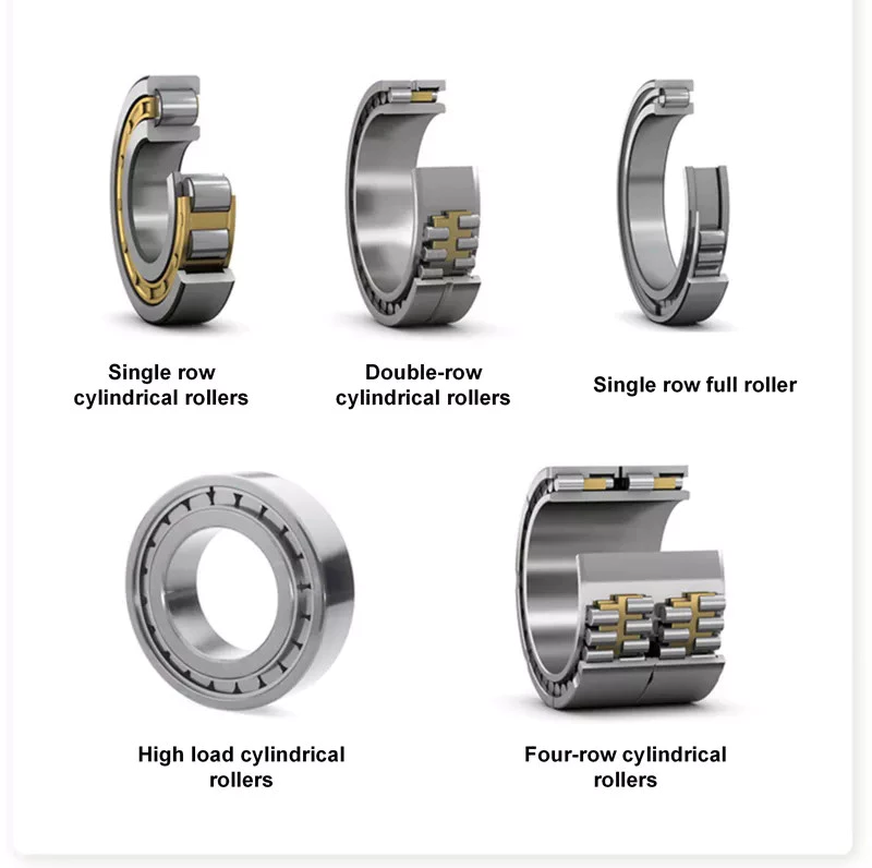
Self-aligning ball bearings
A self-aligning ball bearing is 1 type of self-aligning bearing. These bearings are recommended for use in flex shaft systems. Their self-aligning feature prevents them from misaligning when in use. They can be used in both single and multiple-joint systems. In addition to self-aligning ball bearings, these units also feature flex shafts.
These self-aligning ball bearings come in a variety of configurations, including cylindrical, round, tapered, and straight bore. Their inner ring is tapered to meet specific tolerances. They are suitable for operating temperatures ranging from -30°F to 120°F. Their wide range of applications allows them to be used in general machinery, precision instruments, and low noise motors. In addition, they are available in a variety of outside diameters, widths, and internal clearances.
Self-aligning ball bearings have 2 rows of balls and 1 common sphered raceway in the outer ring. This enables them to automatically compensate for angular misalignment, which may be caused by machining and assembly errors or deflections. Compared to spherical roller bearings, these self-aligning ball bearings generate less friction. They run cooler even at high speeds. Self-aligning ball bearings also offer free engineering support.
Self-aligning ball bearings are designed for difficult shaft alignment. They are double-row, self-retaining units, with cylindrical or tapered bores. These bearings are available in open and sealed designs, and can also be used in applications with misalignment. They are also available with an outer ring that rotates in relation to the inner ring. When it comes to shaft misalignment, self-aligning ball bearings are a great solution.
Stainless steel
Stainless steel is a metal that resists corrosion and is highly durable. Its corrosion-resistant and water-resistance properties make it a good choice for bearings in food and marine applications. Additionally, stainless steel has hygienic benefits. Here are some of the benefits of stainless steel ball bearings. Read on to learn more about these amazing bearings! We've included some of the most common uses for stainless steel.
Hardness is important in a ball bearing. Steel uses the Rockwell C scale to measure hardness. A grade 25 steel ball bearing is accurate to 25 millionths of an inch, while a grade 5 ceramic bearing is less than a half-inch round. Although roundness is important, it shouldn't be overemphasized, as the bearing surfaces may not be as accurate as the grade of the metal. And remember, a higher price tag doesn't mean a better product.
Stainless steel ball bearings are available in a variety of alloys. The alloys used in manufacturing a stainless steel ball bearing vary in hardness, strength, and ductility. Stainless steel ball bearings have high corrosion-resistance properties. Additionally, they have long lubrication lives. These benefits make them a popular choice for industrial applications. These bearings are easy to maintain, reduce replacement costs, and offer corrosion resistance.
The NTN Sentinel Series is a premium line of stainless steel bearings. The solid lube is NSF H1 registered and prevents grease from leaching into food. It is also corrosion-resistant and doesn't need to be coated. The seals and slinger create a water-resistant barrier between the steel ball and the lubricant. It also adds safety and security to the bearing.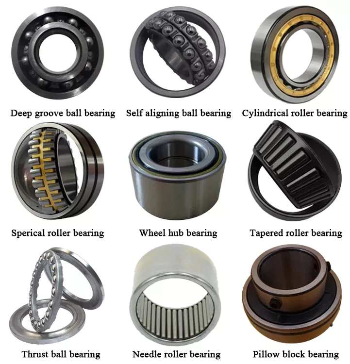
Plastic balls
For applications where noise and weight are major concerns, plastic balls are ideal. These non-magnetic balls are ideal for MRI X-ray machines and sensors. They are also easy to lubricate, and are non-magnetic. A polymer ball bearing is the lightest of all 3 types. This makes them a good choice for many industries. Read on to learn more. This article will introduce some of the advantages of plastic balls for ball bearings.
Although ceramic ball bearings are more durable and offer many advantages, they are more expensive than plastic. Fortunately, plastic ball bearings offer a cheaper alternative. These bearings feature all-plastic races and cages. Depending on the application, plastic balls can be used in applications involving chemicals. In these cases, plastic ball bearings are available with a C160 grade, which is safe for use in temperatures below 176 deg F.
Medical devices often require precision specialty balls, which are made of glass, stainless steel, and plastic. These bearings must meet stringent cleanliness requirements. To meet the most stringent requirements, they must undergo ultrasonic cleaning. These bearings are available in plastic raceways, and are also available with glass or stainless steel balls. Polyethylene balls are lightweight and can be used in a variety of applications. They can be ordered in different sizes and tolerances to meet specific requirements.
Plastic balls for ball bearings are often mounted into other parts, such as plastic wheels, pulleys, and housings. They can be seamlessly integrated into other parts of a machine, which reduces assembly time and improves affordability. One important advantage of plastic bearings is that they are rust-resistant. As such, they can be used in harsh environments without causing any damage. If a piece of equipment is exposed to extreme temperatures, polymers are the ideal choice.
China Professional Rotavator, 3 Point Hitch Tractor Mounted Light Duty Rotary Tiller with Hot selling
Product Description
Light Rotary Tiller TL
1.; CE approved.;
2.; High Quality.;
3.; European Rotary Tiller.;
| Model | TL-85 | TL-95 | TL-105 |
| Dimensions(L * W* H); | 950*800*750mm | 1150*800*750mm | 1250*800*750mm |
| Net Weight | 155Kg | 170Kg | 185Kg |
| Working width | 0.;8m | 0.;9m | 1.;0m |
| Working depth | 90mm | 90mm | 90mm |
| Efficiency | 1300-2100m2/h | 1500-2200m2/h | 1700-2300m2/h |
| PTO Speed | 540r/min | 540r/min | 540r/min |
| PTO Spline | 6*8*700mm | 6*8*700mm | 6*8*700mm |
| Motive power | 12-20HP | 12-20HP | 15-22HP |
| Model | TL-115 | TL-125 | TL-135 |
| Dimensions(L * W* H); | 1350*800*750mm | 1450*800*750mm | 1550*800*750mm |
| Net Weight | 200Kg | 240Kg | 240Kg |
| Working width | 1.;1m | 1.;2m | 1.;3m |
| Working depth | 90mm | 90mm | 90mm |
| Efficiency | 1900-2400m2/h | 2100-2500m2/h | 2300-2600m2/h |
| PTO Speed | 540r/min | 540r/min | 540r/min |
| PTO Spline | 6*8*700mm | 6*8*700mm | 6*8*700mm |
| Motive power | 15-22HP | 18-22HP | 18-22HP |
If you want to know more about our Light Duty Rotary Tiller,; please contact us for Working Vedios.;
Hypoid Bevel Vs Straight Spiral Bevel - What's the Difference?
Spiral gears come in many different varieties, but there is a fundamental difference between a Hypoid bevel gear and a Straight spiral bevel. This article will describe the differences between the 2 types of gears and discuss their use. Whether the gears are used in industrial applications or at home, it is vital to understand what each type does and why it is important. Ultimately, your final product will depend on these differences.
Hypoid bevel gears
In automotive use, hypoid bevel gears are used in the differential, which allows the wheels to rotate at different speeds while maintaining the vehicle's handling. This gearbox assembly consists of a ring gear and pinion mounted on a carrier with other bevel gears. These gears are also widely used in heavy equipment, auxiliary units, and the aviation industry. Listed below are some common applications of hypoid bevel gears.
For automotive applications, hypoid gears are commonly used in rear axles, especially on large trucks. Their distinctive shape allows the driveshaft to be located deeper in the vehicle, thus lowering the center of gravity and minimizing interior disruption. This design makes the hypoid gearset 1 of the most efficient types of gearboxes on the market. In addition to their superior efficiency, hypoid gears are very easy to maintain, as their mesh is based on sliding action.
The face-hobbed hypoid gears have a characteristic epicycloidal lead curve along their lengthwise axis. The most common grinding method for hypoid gears is the Semi-Completing process, which uses a cup-shaped grinding wheel to replace the lead curve with a circular arc. However, this method has a significant drawback - it produces non-uniform stock removal. Furthermore, the grinding wheel cannot finish all the surface of the tooth.
The advantages of a hypoid gear over a spiral bevel gear include a higher contact ratio and a higher transmission torque. These gears are primarily used in automobile drive systems, where the ratio of a single pair of hypoid gears is the highest. The hypoid gear can be heat-treated to increase durability and reduce friction, making it an ideal choice for applications where speed and efficiency are critical.
The same technique used in spiral bevel gears can also be used for hypoid bevel gears. This machining technique involves two-cut roughing followed by one-cut finishing. The pitch diameter of hypoid gears is up to 2500 mm. It is possible to combine the roughing and finishing operations using the same cutter, but the two-cut machining process is recommended for hypoid gears.
The advantages of hypoid gearing over spiral bevel gears are primarily based on precision. Using a hypoid gear with only 3 arc minutes of backlash is more efficient than a spiral bevel gear that requires 6 arc minutes of backlash. This makes hypoid gears a more viable choice in the motion control market. However, some people may argue that hypoid gears are not practical for automobile assemblies.
Hypoid gears have a unique shape - a cone that has teeth that are not parallel. Their pitch surface consists of 2 surfaces - a conical surface and a line-contacting surface of revolution. An inscribed cone is a common substitute for the line-contact surface of hypoid bevel gears, and it features point-contacts instead of lines. Developed in the early 1920s, hypoid bevel gears are still used in heavy truck drive trains. As they grow in popularity, they are also seeing increasing use in the industrial power transmission and motion control industries.
Straight spiral bevel gears
There are many differences between spiral bevel gears and the traditional, non-spiral types. Spiral bevel gears are always crowned and never conjugated, which limits the distribution of contact stress. The helical shape of the bevel gear is also a factor of design, as is its length. The helical shape has a large number of advantages, however. Listed below are a few of them.
Spiral bevel gears are generally available in pitches ranging from 1.5 to 2500 mm. They are highly efficient and are also available in a wide range of tooth and module combinations. Spiral bevel gears are extremely accurate and durable, and have low helix angles. These properties make them excellent for precision applications. However, some gears are not suitable for all applications. Therefore, you should consider the type of bevel gear you need before purchasing.
Compared to helical gears, straight bevel gears are easier to manufacture. The earliest method used to manufacture these gears was the use of a planer with an indexing head. However, with the development of modern manufacturing processes such as the Revacycle and Coniflex systems, manufacturers have been able to produce these gears more efficiently. Some of these gears are used in windup alarm clocks, washing machines, and screwdrivers. However, they are particularly noisy and are not suitable for automobile use.
A straight bevel gear is the most common type of bevel gear, while a spiral bevel gear has concave teeth. This curved design produces a greater amount of torque and axial thrust than a straight bevel gear. Straight teeth can increase the risk of breaking and overheating equipment and are more prone to breakage. Spiral bevel gears are also more durable and last longer than helical gears.
Spiral and hypoid bevel gears are used for applications with high peripheral speeds and require very low friction. They are recommended for applications where noise levels are essential. Hypoid gears are suitable for applications where they can transmit high torque, although the helical-spiral design is less effective for braking. For this reason, spiral bevel gears and hypoids are generally more expensive. If you are planning to buy a new gear, it is important to know which 1 will be suitable for the application.
Spiral bevel gears are more expensive than standard bevel gears, and their design is more complex than that of the spiral bevel gear. However, they have the advantage of being simpler to manufacture and are less likely to produce excessive noise and vibration. They also have less teeth to grind, which means that they are not as noisy as the spiral bevel gears. The main benefit of this design is their simplicity, as they can be produced in pairs, which saves money and time.
In most applications, spiral bevel gears have advantages over their straight counterparts. They provide more evenly distributed tooth loads and carry more load without surface fatigue. The spiral angle of the teeth also affects thrust loading. It is possible to make a straight spiral bevel gear with 2 helical axes, but the difference is the amount of thrust that is applied to each individual tooth. In addition to being stronger, the spiral angle provides the same efficiency as the straight spiral gear.
Hypoid gears
The primary application of hypoid gearboxes is in the automotive industry. They are typically found on the rear axles of passenger cars. The name is derived from the left-hand spiral angle of the pinion and the right-hand spiral angle of the crown. Hypoid gears also benefit from an offset center of gravity, which reduces the interior space of cars. Hypoid gears are also used in heavy trucks and buses, where they can improve fuel efficiency.
The hypoid and spiral bevel gears can be produced by face-hobbing, a process that produces highly accurate and smooth-surfaced parts. This process enables precise flank surfaces and pre-designed ease-off topographies. These processes also enhance the mechanical resistance of the gears by 15 to 20%. Additionally, they can reduce noise and improve mechanical efficiency. In commercial applications, hypoid gears are ideal for ensuring quiet operation.
Conjugated design enables the production of hypoid gearsets with length or profile crowning. Its characteristic makes the gearset insensitive to inaccuracies in the gear housing and load deflections. In addition, crowning allows the manufacturer to adjust the operating displacements to achieve the desired results. These advantages make hypoid gear sets a desirable option for many industries. So, what are the advantages of hypoid gears in spiral gears?
The design of a hypoid gear is similar to that of a conventional bevel gear. Its pitch surfaces are hyperbolic, rather than conical, and the teeth are helical. This configuration also allows the pinion to be larger than an equivalent bevel pinion. The overall design of the hypoid gear allows for large diameter shafts and a large pinion. It can be considered a cross between a bevel gear and a worm drive.
In passenger vehicles, hypoid gears are almost universal. Their smoother operation, increased pinion strength, and reduced weight make them a desirable choice for many vehicle applications. And, a lower vehicle body also lowers the vehicle's body. These advantages made all major car manufacturers convert to hypoid drive axles. It is worth noting that they are less efficient than their bevel gear counterparts.
The most basic design characteristic of a hypoid gear is that it carries out line contact in the entire area of engagement. In other words, if a pinion and a ring gear rotate with an angular increment, line contact is maintained throughout their entire engagement area. The resulting transmission ratio is equal to the angular increments of the pinion and ring gear. Therefore, hypoid gears are also known as helical gears.
China wholesaler Tractor Driven 3 Point Hitch Rotary Tiller Multi Function Rotavator Cultivator / Gear Drive Tractor Farm Cultivator with Great quality
Product Description
Product Description
Product Parameters
| mm | no. | mm | Pto | Min | Max | Kg | ||
| IGN90 | 895 | 4 | 24 | 150 | 540 r/min | 16 | 20 | 250 |
| 1045 | 5 | 30 | 150 | 20 | 28 | 265 | ||
| IGN125 | 1245 | 6 | 36 | 150 | 25 | 30 | 285 | |
| IGN135 | 1345 | 6 | 36 | 150 | 25 | 30 | 300 | |
| IGN150 | 1495 | 7 | 42 | 150 | 30 | 50 | 320 | |
| IGN180 | 1795 | 8 | 48 | 150 | 40 | 75 | 350 | |
Detailed Photos
The material of the whole machine is made of 45 steel and manganese steel, which can reduce the weight of the machine while ensuring the strength of the whole machine.
The side adopts gear transmission, which can withstand the work in the original stubble and high load conditions.
The rear cover adopts a spring locking method, after fixing, the soil block can be moved from the height of the pile to the lower part of the field, so that the soil in the field is even and level.
Our Advantages
Packaging & Shipping
Company Profile
ZheJiang Jitian International Trade Co., LTD, a wholly-owned subsidiary of ZheJiang Jitian Agricultural Machinery Group Co., Ltd was established in 2571 and is located in HangZhou, ZheJiang province, enjoying convenient transportation and beautiful environment. Our company covers an area of 12,000 square meters and has 80 employees. We are specialized in the supply of agricultural machinery and its accessories.
FAQ
1. Who are we?
We are based in ZheJiang , China, start from 2571,sell to Southeast Asia(30.00%),Africa(30.00%),Eastern Asia(15.00%),North
America(10.00%),South Asia(10.00%),Mid East(5.00%). There are total about 11-50 people in our office.
2. How can we guarantee quality?
Always a pre-production sample before mass production;
Always final Inspection before shipment;
3.What can you buy from us?
Tractor,Generator Set,Diesel Engine,Feed Machinery,Reel Irrigation
4. Why should you buy from us not from other suppliers?
Member of China Agricultural Machinery Circulation Association, Member of ZheJiang Agricultural Machinery Circulation Association,
China Agricultural Machinery Circulation and Marketing First-Class Enterprise.
5. What services can we provide?
Accepted Delivery Terms: FOB,CFR,CIF,EXW,FAS,CIP,FCA,CPT,DEQ,DDP,DDU,Express Delivery,DAF,DES;
Accepted Payment Currency:USD,EUR,JPY,CAD,AUD,HKD,GBP,CNY,CHF;
Accepted Payment Type: T/T,L/C,D/P D/A,MoneyGram,Credit Card,PayPal,Western Union,Cash,Escrow;
Language Spoken:English,Chinese,Spanish,Japanese,Portuguese,German,Arabic,French,Russian,Korean,Hindi,Italian
Types of Ball Bearings
Modern ball bearing configurations have different materials and geometries to meet the demands of different working environments and applications. There are different types of ball bearings: single row deep groove, double-row deep groove, angular contact ball bearing, thrust, and self-aligning. Let us look at the differences between each type and learn why they are important for various purposes. Listed below are some of the most common types of ball bearings.
Miniature bearings
Although miniature ball bearings are a popular choice for small mechanical components, they are not without their challenges. They must be properly lubricated and stored in clean rooms. A strand of hair could ruin a miniature bearing. Fortunately, manufacturers offer lubrication services and a "Clean Room" for customers to store their miniature bearings safely. Read on to learn more about these small bearings and how they can help you.
The size of a miniature ball bearing can vary significantly, but most types of these devices are available in sizes ranging from.040 inch to 1 eighth of an inch. Whether you need a small ball bearing for a miniature car or a tiny instrument, a miniature bearing can save space while still offering high performance. Many of these bearings are shielded to prevent dirt from entering and leakage of lubricant. They can be flanged or unflanged, and some miniature ball bearings have extended inner rings that are designed for easy plate mounting.
Miniature ball bearings are commonly made from stainless steel or chrome steel. Both metals have their advantages. Stainless steel is the most popular material for ball bearings, which allows for a high load capacity while being quiet. Because stainless steel is relatively inexpensive, many small instrument bearings are made entirely of stainless steel. The difference in price is minimal, as the amount of steel is relatively small. Stainless steel miniature bearings are the smallest and lightest of all types of miniature ball bearings.
Self-aligning ball bearings
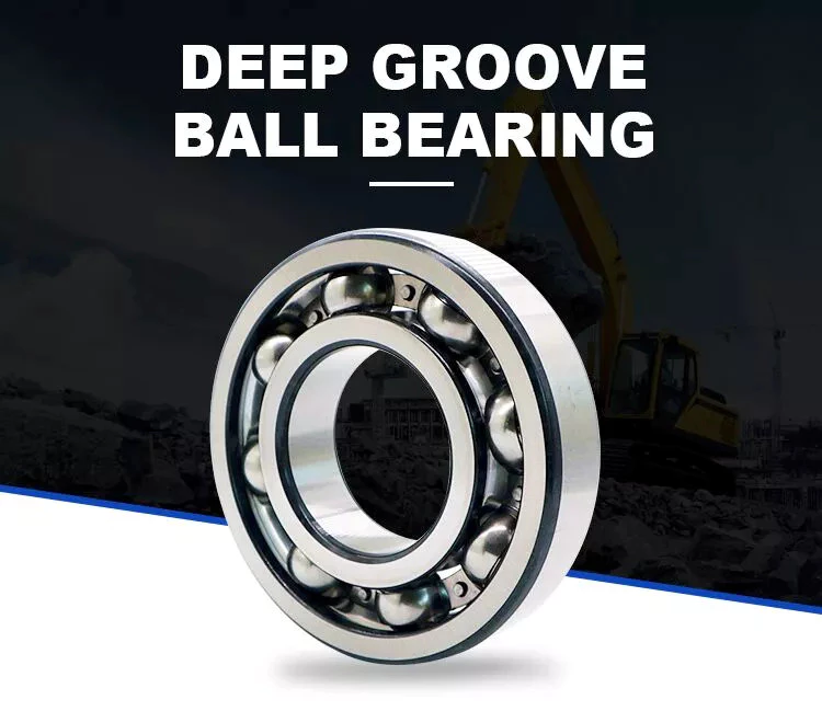
In the simplest terms, self-aligning ball bearings are ball bearings with flex shafts. If you're looking for a ball bearing with a high degree of precision, you'll want to choose 1 with a flex shaft, which means it can adjust to the proper orientation of the bearing's flex shaft. Ball bearings with flex shafts are also recommended. But, what are these bearings?
Self-aligning ball bearings are made with 2 rows of balls and a common sphered raceway on the outer ring. As a result, they can accommodate small errors in shaft alignment and mounting. The CZPT brand is especially suitable for high-speed applications requiring greater running accuracy. The self-alignment mechanism is enabled by the fact that the balls are placed in 2 rows on either side of the sphered raceway in the outer ring. These 2 rows of balls also promote reduced friction and wear.
Another type of self-aligning ball bearings is a double-row design. They feature a common sphered raceway on the outer ring, a hollow spherical ring, and a cage that rotates relative to it. A self-aligning ball bearing is used in applications where shaft misalignment is a problem, such as conveying equipment. They are also used in simple woodworking machinery and ventilators.
Ceramic ball bearings
Ceramic ball bearings have several advantages over steel or metal bearings. These include increased acceleration capability, reduced friction, improved wear-resistance, and higher speeds. The United States holds the leading position in the global ceramic ball bearings market thanks to a rebounding motor vehicle production and healthy fixed investment environment. In the United States, there are 3 primary markets for ceramic ball bearings: healthcare, automotive, and aerospace. Here are the main benefits of ceramic ball bearings:
Hybrid ball bearings are also available. Hybrid bearings feature traditional metal rings and silicon nitride (ceramic) balls. Hybrid bearings offer important performance advantages over all-steel bearings, and they are more affordable. However, full ceramic ball bearings have all ceramic parts, and are best suited for machines that require high precision. These types of bearings also resist corrosion and wear.
Compared to steel ball bearings, ceramic balls are lighter than steel. They are also less dense, which means less friction and therefore less heat. Additionally, ceramic balls operate at higher speeds than steel balls, which increases their durability and longevity. But they are still not as strong as steel bearings. And because of their reduced density, they are much cheaper to manufacture. Therefore, they are an excellent choice for many applications. You can expect them to last much longer than steel bearings.
Steel carbon ball bearings
High precision G25 ball bearings are made of the highest grade chrome steel and hot forged from bar stock. Statistical process control and exacting atmospheres help ensure uniform hardness and microstructure. Moreover, these bearings are of the highest quality, with fine surface finish and a tight tolerance. This makes them the most widely used and reliable choice for industrial and automotive applications. However, there are some considerations that should be taken into account before acquiring a steel carbon ball bearing.
Generally, AFBMA grade 200 is the standard hardness specification for this material. AFBMA grade 100 can also be obtained with great difficulty. Despite the high hardness of steel carbon ball bearings, their outer surface is just a thin hardened shell, so a special micro hardness test is needed to evaluate them. In addition to the hardness, steel balls are easily machined and ground. Some manufacturers even offer stainless steel ball bearings and ball sets.
Another factor that makes steel carbon ball bearings so valuable is their precision. They can give precise measurements, which makes them ideal for low and medium-speed applications. Due to their high precision and durability, steel carbon ball bearings can be used in many applications, from conveyor machines to roller skates. However, you should be aware that the material used to produce these bearings is not suitable for applications in which they are exposed to water and gases. Further, they are also noisy and heavy, and must be installed properly in a manufacturing environment.
Stainless steel ball bearings
Stainless steel ball bearings are made from a high-quality type of stainless steel, 440C, which offers optimal corrosion and abrasion resistance. These bearings are also durable and rust-free, and are suitable for a variety of applications. Among others, stainless steel ball bearings are used in beverage and food processing plants, pharmaceuticals, pulp and paper mills, marine environments, and freezers.
Stainless steel bearings are available in various grades. For example, AISI 440C offers corrosion resistance, while the DD400 is specifically designed for marine applications. Both types of stainless steel are available in different forms, including open, shielded, and sealed. Stainless steel ball bearings can also be custom-made, as BL is known for producing customized bearings. There are also other materials that are available.
AISI type 316 stainless steel balls are ideal for marine applications and food processing. They have excellent resistance to most organic materials and are also used in medical devices and dispenser pumps. They are also strong enough to resist many petroleum products and are widely used in medical equipment and cosmetic applications. In addition, stainless steel balls can be plated to provide an additional layer of protection against chemicals. To understand how they differ, let's take a look at some common types of stainless steel ball bearings.
Stainless steel
Stainless steel ball bearings can be used in various applications. Besides being corrosion resistant, they also last longer thanks to the Molded-Oil lubrication technology. Stainless steel ball bearings are clean units, which saves time and money in terms of maintenance, replacement, and downtime. But what are the advantages of stainless steel ball bearings? Let us discuss these benefits. Also, we'll discuss their advantages and disadvantages.
Stainless steel ball bearings offer notable advantages, including corrosion resistance, increased strength, and improved stability under high temperatures. These qualities make them the ideal choice for special circumstances and demanding environments. However, you should be careful when choosing stainless steel bearings. There are several different types of stainless steel. Here's a brief look at what makes them the best choice. And remember: Stainless steels are also recyclable. In fact, they can be recycled indefinitely.
They're made from chrome alloy electric furnace steel, which is hardened for optimum service life and strength. They have the highest surface finish and dimensional accuracy. Advanced heat-treating processes increase their strength and anti-cracking abilities. And thanks to their unique materials, they're corrosion-resistant. As a result, they're more durable than other types of bearings. And since they're made with a high-quality steel, you'll save money in the long run.
Plastic ball bearings
Plastic ball bearings were developed to meet the specific needs of applications where standard steel bearings would fail. Steel and 440C stainless steel are both susceptible to rusting when exposed to water, making them poor choices for applications involving food processing, swimming pools, and medical equipment. In addition to this, the plastic material is able to dampen vibrations and make the bearing virtually silent. Here's what makes plastic ball bearings so great for these applications.
Plastic ball bearings are lightweight, corrosion-resistant, and offer a long service life. In addition to their low price, they can be easily cleaned and are incredibly durable. Motion plastics specialist igus has recently expanded its range of xiros polymer grooved ball bearings. These bearings are also FDA-compliant, lubricant-free, electrically insulating, and resistant to both temperature and media.
Plastic bearings are often mounted into other components like wheels, pulleys, and housings. In this way, the inner ring is essentially a profile of the pulley's profile, and the outer ring is a shaft or fixing clip. The result is seamless integration of the bearing and the surrounding parts, which reduces the overall assembly time and costs. You can also use multiple plastic ball bearings in 1 application for more options.