Product Description
Product Description
DESCRIPTION:
Gear reducers are enclosed helical gears with hollow inputs.
The gear is mounted directly on the input shaft of the gear and receives support from a motor mounting bracket mounted on the machine housing.
No additional parts are required to transfer torque from the reducer to the machine.
It can be mounted in vertical, horizontal or inclined position.
Shaft-mounted gear reducers typically have 5:1 7:1 10:1 reduction ratios and output speeds ranging from 1 to 300 rpm.
M4 series gear reducer can be installed directly on screw conveyors and feeders with a XUH seal installed on the output shaft of the gearbox.
Ensure that cement, and fly ash powder will not get into the gearbox and extend the service life of the gearbox.
More suitable for bulk materials, grain and aggregate handling industries
WORKING PRINCIPLE:
M4 series gearboxes come in 5 sizes (M41 / M43 / M45 / M47 / M49).
Nominal gear ratios are in accordance with Ra 10 CHINAMFG 2017 (5, 6, 7, 10). Cylindrical gears with helicoidal teeth.
M4 series gearboxes can be mounted directly on screws: in this case, the XUH type output shaft seal is usually installed.
M4 series gearboxes are supplied with grease for use at ambient temperatures (0°C - 40°C).
PROPERTIES:
- Helical gearbox
- Nominal torque that can be transferred to the output shaft: up to 1500 Nm.
- Installed power at the input up to 30 kW.
- Operation at ambient temperature (0°C - 40°C).
- DIN 5482 involute spline output shafts
- Flange mounting on motor and output side
- Precision-machined cylindrical bevel gears with teeth.
- Flange mounting on motor and output side
BENEFITS:
- Easy installation
- Quick maintenance
- Low installation costs
Services
Pre-sales Commitment
1. For user inquiries, quick response, warm reception, and answer all questions.
2. Provide detailed design information free of charge within 24 hours.
Commitment in Sales
1. All ex-factory products meet the quality standards specified in the contract. All products are tested according to customer requirements before delivery.
2. After the contract is signed, the customers are welcome to the site of our company for supervision.
After-sales Commitment
1. We provide technical support for customers. If necessary, the product can be debugged on-site, and relevant operators can be trained to solve user problems.
2. 24 hours to solve the problems for customers. Product use a day, a day of service.
3. Set up a high-quality service team, and set up product files for regular return visits.
/* March 10, 2571 17:59:20 */!function(){function s(e,r){var a,o={};try{e&&e.split(",").forEach(function(e,t){e&&(a=e.match(/(.*?):(.*)$/))&&1
| Application: | Machinery |
|---|---|
| Hardness: | Hardened Tooth Surface |
| Installation: | Vertical Type |
| Layout: | Coaxial |
| Gear Shape: | Conical - Cylindrical Gear |
| Step: | Four-Step |
| Samples: |
US$ 100/Piece
1 Piece(Min.Order) | |
|---|
| Customization: |
Available
| Customized Request |
|---|
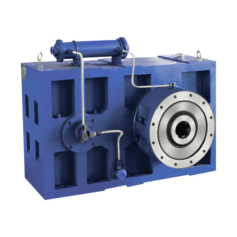
Can you provide real-world examples of products that use gear reducer technology?
Certainly! Gear reducer technology is widely used in various industries and products to enhance performance and efficiency. Here are some real-world examples:
1. Industrial Machinery: Gear reducers are commonly used in manufacturing machinery, such as conveyor systems, material handling equipment, and assembly lines, where they help control speed and torque for precise operations.
2. Wind Turbines: Wind turbines utilize gear reducers to transform the low rotational speed of the wind turbine rotor into the higher speed needed for electricity generation, optimizing energy conversion.
3. Automotive Transmissions: Automobiles use gear reducers as part of their transmissions to optimize power delivery from the engine to the wheels, allowing the vehicle to operate efficiently at different speeds.
4. Robotics: Robotic systems rely on gear reducers to control the movement and articulation of robot arms, enabling precise and controlled motion for various applications.
5. Printing Presses: Gear reducers are integral to printing presses, ensuring accurate and synchronized movement of printing plates, rollers, and paper feed mechanisms.
6. Conveyor Belts: Conveyor systems in industries like mining, agriculture, and logistics use gear reducers to regulate the movement of materials along the conveyor belts.
7. Packaging Machinery: Gear reducers play a crucial role in packaging machines, controlling the speed and movement of packaging materials, filling mechanisms, and sealing components.
8. Cranes and Hoists: Cranes and hoists rely on gear reducers to lift heavy loads with precision and control, ensuring safe and efficient material handling.
9. Pumps and Compressors: Gear reducers are utilized in pumps and compressors to regulate fluid flow and pressure, optimizing energy usage in fluid transportation systems.
10. Agriculture Equipment: Tractors and other agricultural machinery use gear reducers to adjust the speed and power delivery for different tasks, such as plowing, planting, and harvesting.
These examples demonstrate the diverse applications of gear reducer technology across various industries, showcasing their role in enhancing efficiency, control, and performance in a wide range of products and systems.
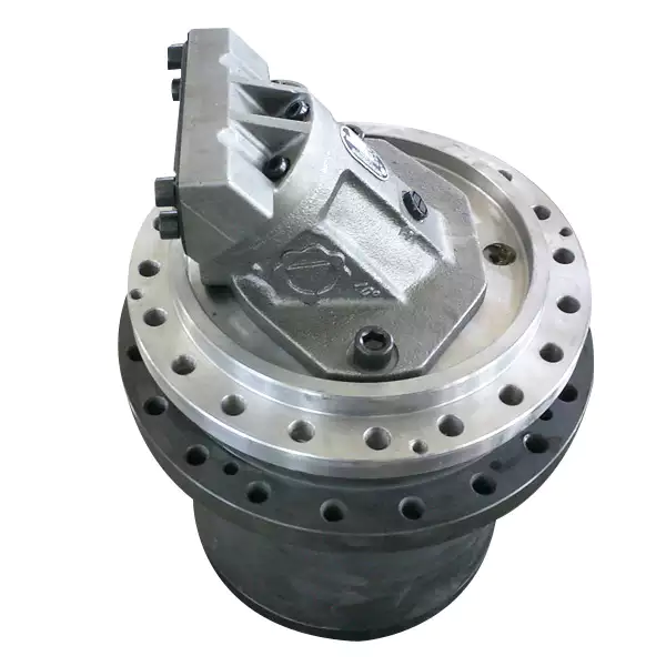
What factors should be considered when selecting the right gear reducer?
Choosing the appropriate gear reducer involves considering several crucial factors to ensure optimal performance and efficiency for your specific application:
- 1. Torque and Power Requirements: Determine the amount of torque and power your machinery needs for its operation.
- 2. Speed Ratio: Calculate the required speed reduction or increase to match the input and output speeds.
- 3. Gear Type: Select the appropriate gear type (helical, bevel, worm, planetary, etc.) based on your application's torque, precision, and efficiency requirements.
- 4. Mounting Options: Consider the available space and the mounting configuration that suits your machinery.
- 5. Environmental Conditions: Evaluate factors such as temperature, humidity, dust, and corrosive elements that may impact the gear reducer's performance.
- 6. Efficiency: Assess the gear reducer's efficiency to minimize power losses and improve overall system performance.
- 7. Backlash: Consider the acceptable level of backlash or play between gear teeth, which can affect precision.
- 8. Maintenance Requirements: Determine the maintenance intervals and procedures necessary for reliable operation.
- 9. Noise and Vibration: Evaluate noise and vibration levels to ensure they meet your machinery's requirements.
- 10. Cost: Compare the initial cost and long-term value of different gear reducer options.
By carefully assessing these factors and consulting with gear reducer manufacturers, engineers and industry professionals can make informed decisions to select the right gear reducer for their specific application, optimizing performance, longevity, and cost-effectiveness.

What industries and machinery commonly utilize gear reducers?
Gear reducers are widely used across various industries and types of machinery for torque reduction and speed control. Some common industries and applications include:
- 1. Manufacturing: Gear reducers are used in manufacturing equipment such as conveyors, mixers, and packaging machines to control speed and transmit power efficiently.
- 2. Automotive: They are utilized in vehicles for applications like power transmission in transmissions and differentials.
- 3. Aerospace: Gear reducers are used in aircraft systems, including landing gear mechanisms and engine accessories.
- 4. Robotics and Automation: They play a crucial role in robotic arms, CNC machines, and automated production lines.
- 5. Mining and Construction: Gear reducers are used in heavy machinery like excavators, bulldozers, and crushers for power transmission and torque multiplication.
- 6. Energy and Power Generation: Wind turbines, hydroelectric generators, and other power generation equipment use gear reducers to convert rotational speed and transmit power.
- 7. Marine and Shipbuilding: They are used in ship propulsion systems, steering mechanisms, and anchor handling equipment.
- 8. Material Handling: Gear reducers are essential in conveyor systems, elevators, and hoists for controlled movement of materials.
- 9. Food and Beverage: They find applications in food processing equipment like mixers, grinders, and packaging machines.
- 10. Paper and Pulp: Gear reducers are used in machinery for pulp processing, paper production, and printing.
These examples represent just a fraction of the industries and machinery that benefit from the use of gear reducers to optimize power transmission and achieve the desired motion characteristics.


editor by CX 2024-01-02
China wholesaler M4505160es3a Series Gear Reducer for 219-273 Series Screw Feeder differential gearbox
Product Description
Product Description
DESCRIPTION:
Gear reducers are enclosed helical gears with hollow inputs.
The gear is mounted directly on the input shaft of the gear and receives support from a motor mounting bracket mounted on the machine housing.
No additional parts are required to transfer torque from the reducer to the machine.
It can be mounted in vertical, horizontal or inclined position.
Shaft-mounted gear reducers typically have 5:1 7:1 10:1 reduction ratios and output speeds ranging from 1 to 300 rpm.
M4 series gear reducer can be installed directly on screw conveyors and feeders with a XUH seal installed on the output shaft of the gearbox.
Ensure that cement, and fly ash powder will not get into the gearbox and extend the service life of the gearbox.
More suitable for bulk materials, grain and aggregate handling industries
WORKING PRINCIPLE:
M4 series gearboxes come in 5 sizes (M41 / M43 / M45 / M47 / M49).
Nominal gear ratios are in accordance with Ra 10 CHINAMFG 2017 (5, 6, 7, 10). Cylindrical gears with helicoidal teeth.
M4 series gearboxes can be mounted directly on screws: in this case, the XUH type output shaft seal is usually installed.
M4 series gearboxes are supplied with grease for use at ambient temperatures (0°C - 40°C).
PROPERTIES:
- Helical gearbox
- Nominal torque that can be transferred to the output shaft: up to 1500 Nm.
- Installed power at the input up to 30 kW.
- Operation at ambient temperature (0°C - 40°C).
- DIN 5482 involute spline output shafts
- Flange mounting on motor and output side
- Precision-machined cylindrical bevel gears with teeth.
- Flange mounting on motor and output side
BENEFITS:
- Easy installation
- Quick maintenance
- Low installation costs
Services
Pre-sales Commitment
1. For user inquiries, quick response, warm reception, and answer all questions.
2. Provide detailed design information free of charge within 24 hours.
Commitment in Sales
1. All ex-factory products meet the quality standards specified in the contract. All products are tested according to customer requirements before delivery.
2. After the contract is signed, the customers are welcome to the site of our company for supervision.
After-sales Commitment
1. We provide technical support for customers. If necessary, the product can be debugged on-site, and relevant operators can be trained to solve user problems.
2. 24 hours to solve the problems for customers. Product use a day, a day of service.
3. Set up a high-quality service team, and set up product files for regular return visits.
/* March 10, 2571 17:59:20 */!function(){function s(e,r){var a,o={};try{e&&e.split(",").forEach(function(e,t){e&&(a=e.match(/(.*?):(.*)$/))&&1
| Application: | Machinery |
|---|---|
| Hardness: | Hardened Tooth Surface |
| Installation: | Vertical Type |
| Layout: | Coaxial |
| Gear Shape: | Conical - Cylindrical Gear |
| Step: | Four-Step |
| Samples: |
US$ 100/Piece
1 Piece(Min.Order) | |
|---|
| Customization: |
Available
| Customized Request |
|---|
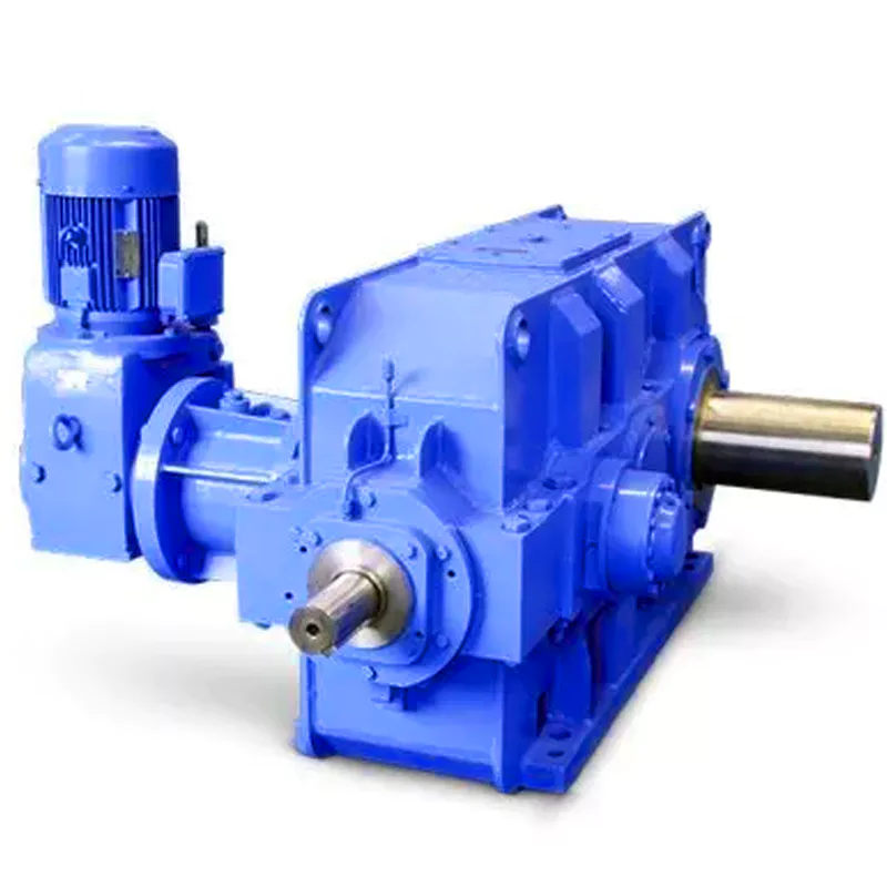
What are the considerations for choosing the appropriate lubrication for gear reducers?
Choosing the appropriate lubrication for gear reducers is crucial for ensuring optimal performance, longevity, and efficiency. Several considerations should be taken into account when selecting the right lubrication:
1. Load and Torque: The magnitude of the load and torque transmitted by the gear reducer affects the lubrication's viscosity and film strength requirements. Heavier loads may necessitate higher viscosity lubricants.
2. Operating Speed: The speed at which the gear reducer operates impacts the lubrication's ability to maintain a consistent and protective film between gear surfaces.
3. Temperature Range: Consider the temperature range of the operating environment. Lubricants with suitable viscosity indexes are crucial to maintaining performance under varying temperature conditions.
4. Contaminant Exposure: If the gear reducer is exposed to dust, dirt, water, or other contaminants, the lubrication should have proper sealing properties and resistance to contamination.
5. Lubrication Interval: Determine the desired maintenance interval. Some lubricants require more frequent replacement, while others offer extended operational periods.
6. Compatibility with Materials: Ensure that the chosen lubricant is compatible with the materials used in the gear reducer, including gears, bearings, and seals.
7. Noise and Vibration: Some lubricants have properties that can help reduce noise and dampen vibrations, improving the overall user experience.
8. Environmental Impact: Consider environmental regulations and sustainability goals when selecting lubricants.
9. Manufacturer Recommendations: Follow the manufacturer's recommendations and guidelines for lubrication type, viscosity grade, and maintenance intervals.
10. Monitoring and Analysis: Implement a lubrication monitoring and analysis program to assess lubricant condition and performance over time.
By carefully evaluating these considerations and consulting with lubrication experts, industries can choose the most suitable lubrication for their gear reducers, ensuring reliable and efficient operation.
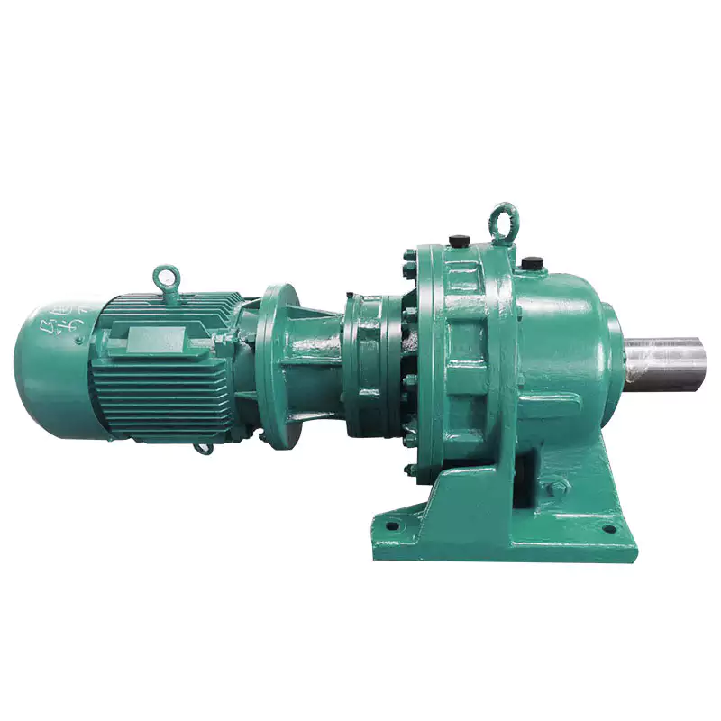
What role do gear ratios play in optimizing the performance of gear reducers?
Gear ratios play a crucial role in optimizing the performance of gear reducers by determining the relationship between input and output speeds and torques. A gear ratio is the ratio of the number of teeth between two meshing gears, and it directly influences the mechanical advantage and efficiency of the gear reducer.
1. Speed and Torque Conversion: Gear ratios allow gear reducers to convert rotational speed and torque according to the needs of a specific application. By selecting appropriate gear ratios, gear reducers can either reduce speed while increasing torque (speed reduction) or increase speed while decreasing torque (speed increase).
2. Mechanical Advantage: Gear reducers leverage gear ratios to provide mechanical advantage. In speed reduction configurations, a higher gear ratio results in a greater mechanical advantage, allowing the output shaft to deliver higher torque at a lower speed. This is beneficial for applications requiring increased force or torque, such as heavy machinery or conveyor systems.
3. Efficiency: Optimal gear ratios contribute to higher efficiency in gear reducers. By distributing the load across multiple gear teeth, gear reducers with suitable gear ratios minimize stress and wear on individual gear teeth, leading to improved overall efficiency and prolonged lifespan.
4. Speed Matching: Gear ratios enable gear reducers to match the rotational speeds of input and output shafts. This is crucial in applications where precise speed synchronization is required, such as in conveyors, robotics, and manufacturing processes.
When selecting gear ratios for a gear reducer, it's important to consider the specific requirements of the application, including desired speed, torque, efficiency, and mechanical advantage. Properly chosen gear ratios enhance the overall performance and reliability of gear reducers in a wide range of industrial and mechanical systems.
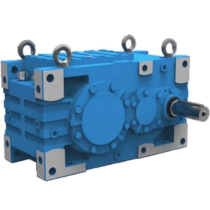
Can you explain the different types of gear reducers available in the market?
There are several types of gear reducers commonly used in industrial applications:
1. Spur Gear Reducers: These reducers have straight teeth and are cost-effective for applications requiring moderate torque and speed reduction. They are efficient but may produce more noise compared to other types.
2. Helical Gear Reducers: Helical gears have angled teeth, which provide smoother and quieter operation compared to spur gears. They offer higher torque capacities and are suitable for heavy-duty applications.
3. Bevel Gear Reducers: Bevel gears have conical shapes and intersect at an angle, allowing them to transmit power between non-parallel shafts. They are commonly used in applications where shafts intersect at 90 degrees.
4. Worm Gear Reducers: Worm gears consist of a worm (screw) and a mating gear (worm wheel). They offer high torque reduction and are used for applications requiring high ratios, although they can be less efficient.
5. Planetary Gear Reducers: These reducers use a system of planetary gears to achieve high torque output in a compact design. They provide excellent torque multiplication and are commonly used in robotics and automation.
6. Cycloidal Gear Reducers: Cycloidal drives use an eccentric cam to achieve speed reduction. They offer high shock load resistance and are suitable for applications with frequent starting and stopping.
7. Harmonic Drive Reducers: Harmonic drives use a flexible spline to achieve high gear reduction ratios. They provide high precision and are commonly used in applications requiring accurate positioning.
8. Hypoid Gear Reducers: Hypoid gears have helical teeth and non-intersecting shafts, making them suitable for applications with space limitations. They offer high torque and efficiency.
Each type of gear reducer has its own advantages and limitations, and the choice depends on factors such as torque requirements, speed ratios, noise levels, space constraints, and application-specific needs.


editor by CX 2023-12-26
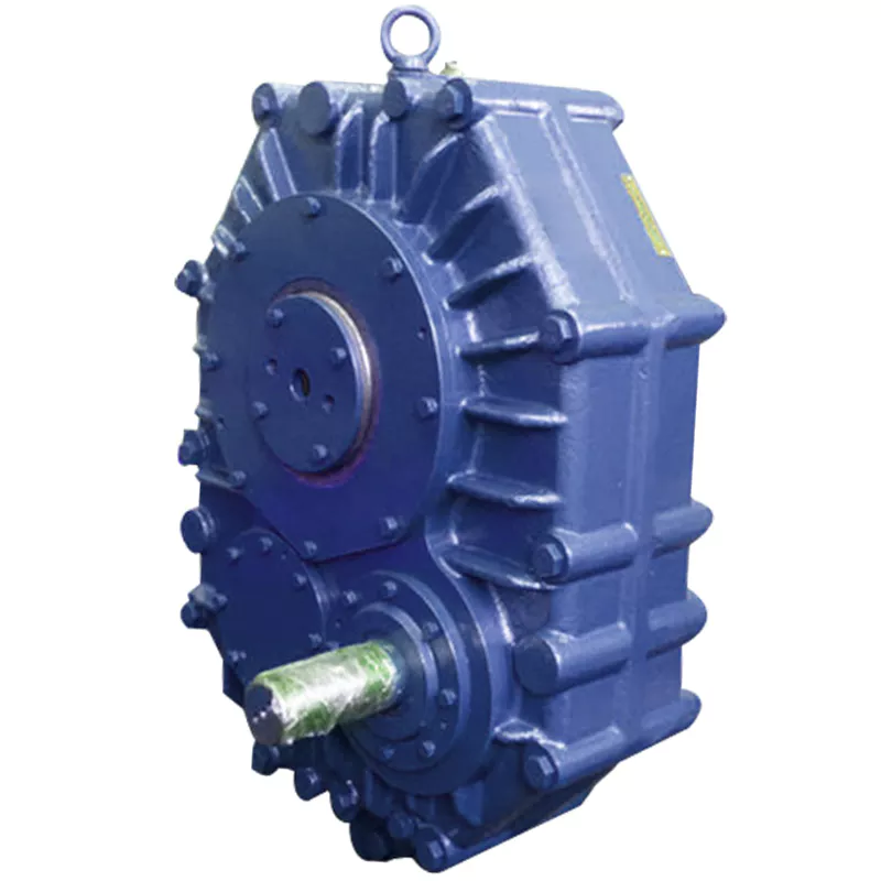
China Good quality Hollow Shaft CZPT Gearbox Zsyj450 Decelerator Single Screw Plastic Rubber Special Gear Reducer for Plastic Edge Band Extrusion Machine gearbox design
Product Description
Hollow Shaft CHINAMFG Gearbox Zsyj450 Decelerator Single Screw Plastic Rubber Special Gear Reducer for Plastic Edge Band Extrusion Machine
1, The gear is made of high-strength low-carbon alloy steel by carburizing and quenching. The hardness of
the tooth surface is up to HRC58-62. The gears are groun d grinding technology with high precision and
good contact.
2, High transmission efficiency: CHINAMFG is greater than 96.5%, double level is greater than 93%, third
level is greater than 90%.
3, Smooth operation and low noise.
4, Small size, light weight, long service life and high carrying capacity.
5, Easy to disassemble and easy to install.
|
No. |
gearbox model |
Ratio range |
recommend screw diameter/mm |
recommend power/HP |
rating load torque/N.m |
size(L*W*H)/mm |
Net weight/KG |
|
1 |
ZLYJ133 |
8/12.5/16/20 |
35/45/50 |
6~15 |
764 |
478*170*260 |
144 |
|
2 |
ZLYJ146 |
10/12.5/16/20 |
45/55 |
10~20 |
1165 |
560*250*320 |
205 |
|
3 |
ZLYJ173 |
10/16/20 |
55/65 |
15~30 |
1962 |
576*256*340 |
256 |
|
4 |
ZLYJ180 |
|
65 |
15~40 |
2764 |
650*256*400 |
350 |
|
5 |
ZLYJ200 |
12.5/16/20 |
65/75 |
30~60 |
3583 |
750*340*480 |
350 |
|
6 |
ZLYJ225 |
12.5/16/20 |
90 |
40~75 |
5334 |
800*360*500 |
650 |
|
7 |
ZLYJ250 |
16/12.5/20 |
100 |
50~100 |
6306 |
930*380*560 |
815 |
|
8 |
ZLYJ280 |
16/12.5/20 |
105/110 |
75~122 |
7643 |
970*410*600 |
1571 |
|
9 |
ZLYJ315 |
16/12.5/20 |
120 |
100~175 |
11822 |
1160*450*700 |
1410 |
|
10 |
ZLYJ330 |
16/12.5/20 |
150/160 |
150~217 |
21000 |
1160*450*700 |
1520 |
|
11 |
ZLYJ375 |
16/12.5/20 |
150/160 |
217~312 |
21096 |
1280*466*800 |
1800 |
|
12 |
ZLYJ420 |
16/12.5/20 |
150/165 |
272~428 |
25478 |
1420*550*920 |
1800 |
|
13 |
ZLYJ450 |
16/12.5/20 |
165 |
380~544 |
33885 |
1550*1200*1000 |
3560 |
| Application: | Motor, Electric Cars, Motorcycle, Machinery, Marine, Toy, Agricultural Machinery, Car |
|---|---|
| Hardness: | Hardened Tooth Surface |
| Installation: | 90 Degree |
| Layout: | Coaxial |
| Gear Shape: | Conical - Cylindrical Gear |
| Step: | Single-Step |
| Samples: |
US$ 9999/Piece
1 Piece(Min.Order) | |
|---|
Are there any disadvantages or limitations to using gear reducer systems?
While gear reducer systems offer numerous advantages, they also come with certain disadvantages and limitations that should be considered during the selection and implementation process:
1. Size and Weight: Gear reducers can be bulky and heavy, especially for applications requiring high gear ratios. This can impact the overall size and weight of the machinery or equipment, which may be a concern in space-constrained environments.
2. Efficiency Loss: Despite their high efficiency, gear reducers can experience energy losses due to friction between gear teeth and other components. This can lead to a reduction in overall system efficiency, particularly in cases where multiple gear stages are used.
3. Cost: The design, manufacturing, and assembly of gear reducers can involve complex processes and precision machining, which can contribute to higher initial costs compared to other power transmission solutions.
4. Maintenance: Gear reducer systems require regular maintenance, including lubrication, inspection, and potential gear replacement over time. Maintenance activities can lead to downtime and associated costs in industrial settings.
5. Noise and Vibration: Gear reducers can generate noise and vibrations, especially at high speeds or when operating under heavy loads. Additional measures may be needed to mitigate noise and vibration issues.
6. Limited Gear Ratios: While gear reducers offer a wide range of gear ratios, there may be limitations in achieving extremely high or low ratios in certain designs.
7. Temperature Sensitivity: Extreme temperatures can affect the performance of gear reducer systems, particularly if inadequate lubrication or cooling is provided.
8. Shock Loads: While gear reducers are designed to handle shock loads to some extent, severe shock loads or abrupt changes in torque can still lead to potential damage or premature wear.
Despite these limitations, gear reducer systems remain widely used and versatile components in various industries, and their disadvantages can often be mitigated through proper design, selection, and maintenance practices.

What role do gear ratios play in optimizing the performance of gear reducers?
Gear ratios play a crucial role in optimizing the performance of gear reducers by determining the relationship between input and output speeds and torques. A gear ratio is the ratio of the number of teeth between two meshing gears, and it directly influences the mechanical advantage and efficiency of the gear reducer.
1. Speed and Torque Conversion: Gear ratios allow gear reducers to convert rotational speed and torque according to the needs of a specific application. By selecting appropriate gear ratios, gear reducers can either reduce speed while increasing torque (speed reduction) or increase speed while decreasing torque (speed increase).
2. Mechanical Advantage: Gear reducers leverage gear ratios to provide mechanical advantage. In speed reduction configurations, a higher gear ratio results in a greater mechanical advantage, allowing the output shaft to deliver higher torque at a lower speed. This is beneficial for applications requiring increased force or torque, such as heavy machinery or conveyor systems.
3. Efficiency: Optimal gear ratios contribute to higher efficiency in gear reducers. By distributing the load across multiple gear teeth, gear reducers with suitable gear ratios minimize stress and wear on individual gear teeth, leading to improved overall efficiency and prolonged lifespan.
4. Speed Matching: Gear ratios enable gear reducers to match the rotational speeds of input and output shafts. This is crucial in applications where precise speed synchronization is required, such as in conveyors, robotics, and manufacturing processes.
When selecting gear ratios for a gear reducer, it's important to consider the specific requirements of the application, including desired speed, torque, efficiency, and mechanical advantage. Properly chosen gear ratios enhance the overall performance and reliability of gear reducers in a wide range of industrial and mechanical systems.

What industries and machinery commonly utilize gear reducers?
Gear reducers are widely used across various industries and types of machinery for torque reduction and speed control. Some common industries and applications include:
- 1. Manufacturing: Gear reducers are used in manufacturing equipment such as conveyors, mixers, and packaging machines to control speed and transmit power efficiently.
- 2. Automotive: They are utilized in vehicles for applications like power transmission in transmissions and differentials.
- 3. Aerospace: Gear reducers are used in aircraft systems, including landing gear mechanisms and engine accessories.
- 4. Robotics and Automation: They play a crucial role in robotic arms, CNC machines, and automated production lines.
- 5. Mining and Construction: Gear reducers are used in heavy machinery like excavators, bulldozers, and crushers for power transmission and torque multiplication.
- 6. Energy and Power Generation: Wind turbines, hydroelectric generators, and other power generation equipment use gear reducers to convert rotational speed and transmit power.
- 7. Marine and Shipbuilding: They are used in ship propulsion systems, steering mechanisms, and anchor handling equipment.
- 8. Material Handling: Gear reducers are essential in conveyor systems, elevators, and hoists for controlled movement of materials.
- 9. Food and Beverage: They find applications in food processing equipment like mixers, grinders, and packaging machines.
- 10. Paper and Pulp: Gear reducers are used in machinery for pulp processing, paper production, and printing.
These examples represent just a fraction of the industries and machinery that benefit from the use of gear reducers to optimize power transmission and achieve the desired motion characteristics.


editor by CX 2023-12-08
China Best Sales Gear Reducer M4505160es3 of Screw Conveyor for 219mm Screw Feeders cvt gearbox
Product Description
Product Description
DESCRIPTION:
Gear reducers are enclosed helical gears with hollow inputs.
The gear is mounted directly on the input shaft of the gear and receives support from a motor mounting bracket mounted on the machine housing.
No additional parts are required to transfer torque from the reducer to the machine.
It can be mounted in vertical, horizontal or inclined position.
Shaft-mounted gear reducers typically have 5:1 7:1 10:1 reduction ratios and output speeds ranging from 1 to 300 rpm.
M4 series gear reducer can be installed directly on screw conveyors and feeders with a XUH seal installed on the output shaft of the gearbox.
Ensure that cement, and fly ash powder will not get into the gearbox and extend the service life of the gearbox.
More suitable for bulk materials, grain and aggregate handling industries
WORKING PRINCIPLE:
M4 series gearboxes come in 5 sizes (M41 / M43 / M45 / M47 / M49).
Nominal gear ratios are in accordance with Ra 10 CHINAMFG 2017 (5, 6, 7, 10). Cylindrical gears with helicoidal teeth.
M4 series gearboxes can be mounted directly on screws: in this case, the XUH type output shaft seal is usually installed.
M4 series gearboxes are supplied with grease for use at ambient temperatures (0°C - 40°C).
PROPERTIES:
- Helical gearbox
- Nominal torque that can be transferred to the output shaft: up to 1500 Nm.
- Installed power at the input up to 30 kW.
- Operation at ambient temperature (0°C - 40°C).
- DIN 5482 involute spline output shafts
- Flange mounting on motor and output side
- Precision-machined cylindrical bevel gears with teeth.
- Flange mounting on motor and output side
BENEFITS:
- Easy installation
- Quick maintenance
- Low installation costs
Services
Pre-sales Commitment
1. For user inquiries, quick response, warm reception, and answer all questions.
2. Provide detailed design information free of charge within 24 hours.
Commitment in Sales
1. All ex-factory products meet the quality standards specified in the contract. All products are tested according to customer requirements before delivery.
2. After the contract is signed, the customers are welcome to the site of our company for supervision.
After-sales Commitment
1. We provide technical support for customers. If necessary, the product can be debugged on-site, and relevant operators can be trained to solve user problems.
2. 24 hours to solve the problems for customers. Product use a day, a day of service.
3. Set up a high-quality service team, and set up product files for regular return visits.
| Application: | Machinery |
|---|---|
| Hardness: | Hardened Tooth Surface |
| Installation: | Vertical Type |
| Layout: | Coaxial |
| Gear Shape: | Conical - Cylindrical Gear |
| Step: | Four-Step |
| Samples: |
US$ 100/Piece
1 Piece(Min.Order) | |
|---|
| Customization: |
Available
| Customized Request |
|---|

How do gear reducers contribute to energy efficiency in machinery and equipment?
Gear reducers play a significant role in enhancing energy efficiency in various machinery and equipment. Here's how they contribute:
1. Speed Reduction: Gear reducers are commonly used to reduce the speed of the input shaft, allowing the motor to operate at a higher speed where it's most efficient. This speed reduction helps match the motor's optimal operating range, reducing energy consumption.
2. Torque Increase: Gear reducers can increase torque output while decreasing speed, enabling machinery to handle higher loads without the need for a larger, more energy-intensive motor.
3. Matching Load Requirements: By adjusting gear ratios, gear reducers ensure that the machinery's output speed and torque match the load requirements. This prevents the motor from operating at unnecessary high speeds, saving energy.
4. Variable Speed Applications: In applications requiring variable speeds, gear reducers allow for efficient speed control without the need for continuous motor adjustments, improving energy usage.
5. Efficient Power Transmission: Gear reducers efficiently transmit power from the motor to the load, minimizing energy losses due to friction and inefficiencies.
6. Motor Downsizing: Gear reducers enable the use of smaller, more energy-efficient motors by converting their higher speed, lower torque output into the lower speed, higher torque needed for the application.
7. Decoupling Motor and Load Speeds: In cases where the motor and load speeds are inherently different, gear reducers ensure the motor operates at its most efficient speed while still delivering the required output to the load.
8. Overcoming Inertia: Gear reducers help overcome the inertia of heavy loads, making it easier for motors to start and stop, reducing energy consumption during frequent operation.
9. Precise Control: Gear reducers provide precise control over speed and torque, optimizing the energy consumption of machinery in processes that require accurate adjustments.
10. Regenerative Braking: In some applications, gear reducers can be used to capture and convert kinetic energy back into electrical energy during braking or deceleration, improving overall energy efficiency.
By efficiently managing speed, torque, and power transmission, gear reducers contribute to energy-efficient operation, reducing energy consumption, and minimizing the environmental impact of machinery and equipment.
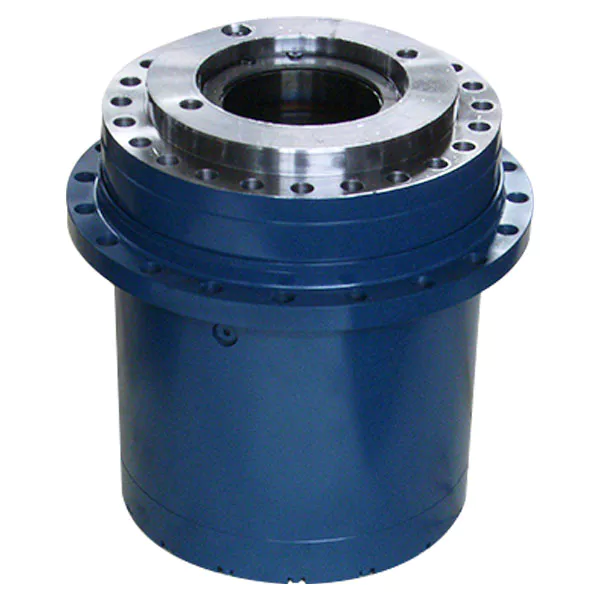
How do gear reducers ensure efficient power transmission and motion control?
Gear reducers play a vital role in ensuring efficient power transmission and precise motion control in various industrial applications. They achieve this through the following mechanisms:
- 1. Speed Reduction/Increase: Gear reducers allow you to adjust the speed between the input and output shafts. Speed reduction is essential when the output speed needs to be lower than the input speed, while speed increase is used when the opposite is required.
- 2. Torque Amplification: By altering the gear ratio, gear reducers can amplify torque from the input to the output shaft. This enables machinery to handle higher loads and provide the necessary force for various tasks.
- 3. Gear Train Efficiency: Well-designed gear trains within reducers minimize power losses during transmission. Helical and spur gears, for example, offer high efficiency by distributing load and reducing friction.
- 4. Precision Motion Control: Gear reducers provide precise control over rotational motion. This is crucial in applications where accurate positioning, synchronization, or timing is required, such as in robotics, CNC machines, and conveyor systems.
- 5. Backlash Reduction: Some gear reducers are designed to minimize backlash, which is the play between gear teeth. This reduction in play ensures smoother operation, improved accuracy, and better control.
- 6. Load Distribution: Gear reducers distribute the load evenly among multiple gear teeth, reducing wear and extending the lifespan of the components.
- 7. Shock Absorption: In applications where sudden starts, stops, or changes in direction occur, gear reducers help absorb and dampen shocks, protecting the machinery and ensuring reliable operation.
- 8. Compact Design: Gear reducers provide a compact solution for achieving specific speed and torque requirements, allowing for space-saving integration into machinery.
By combining these principles, gear reducers facilitate the efficient and controlled transfer of power, enabling machinery to perform tasks accurately, reliably, and with the required force, making them essential components in a wide range of industries.
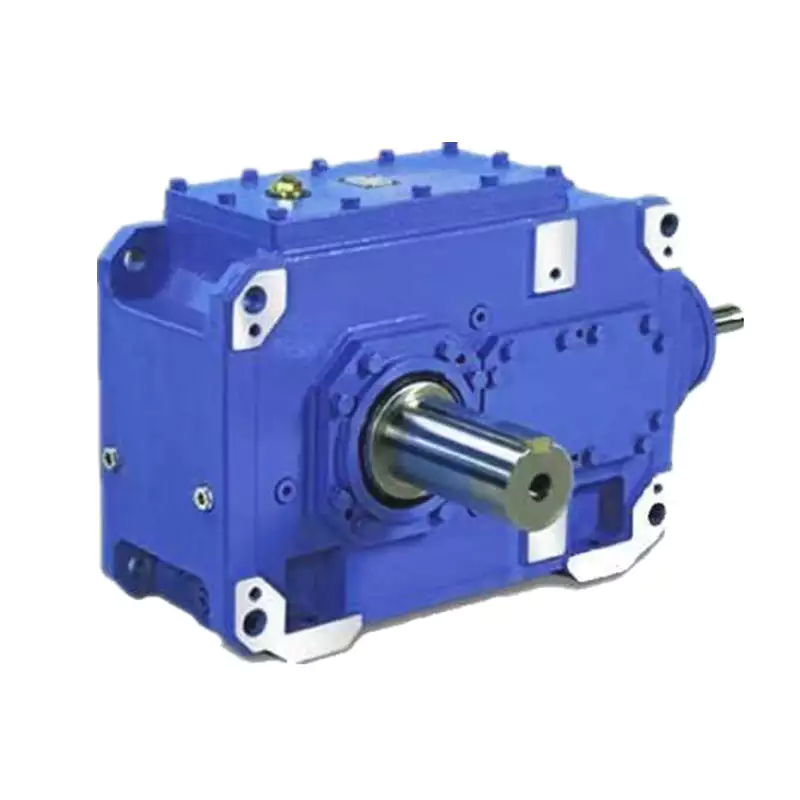
Are there variations in gear reducer designs for specific tasks and applications?
Yes, gear reducer designs vary widely to suit specific tasks and applications across various industries. Manufacturers offer a range of gear reducer types and configurations to accommodate different requirements, including:
- Helical Gear Reducers: These are versatile and provide smooth and efficient torque transmission. They are commonly used in applications requiring high precision and moderate speed reduction, such as conveyors, mixers, and agitators.
- Bevel Gear Reducers: These are ideal for transmitting power between intersecting shafts. They are often used in heavy machinery, printing presses, and automotive applications.
- Worm Gear Reducers: These provide compact solutions and are suitable for applications with higher speed reduction requirements, such as conveyor systems, winches, and elevators.
- Planetary Gear Reducers: These offer high torque density and are used in applications demanding precise control, such as robotics, aerospace, and heavy-duty machinery.
- Parallel Shaft Gear Reducers: Commonly used in industrial machinery, these reducers are designed for high torque and reliability.
- Right-Angle Gear Reducers: These are used when space limitations require a change in shaft direction, commonly found in packaging equipment and conveyors.
Each type of gear reducer has unique features and benefits that make it suitable for specific tasks. Manufacturers often provide customization options to tailor gear reducers to the precise requirements of an application, including gear ratios, mounting options, and input/output configurations.
Therefore, the variation in gear reducer designs allows industries to select the most appropriate type based on factors such as torque, speed, space constraints, precision, and environmental conditions.


editor by CX 2023-12-07
China best China Top Quality Supplier Helical Gear Reducer for Screw Conveyor sequential gearbox
Product Description
China Top Quality Supplier helical gear reducer for screw conveyor
Our Gearbox has many items for your choosing and we can produce as per your drawing or sample to meet your special request
1. Large output torque
2. Safe, reliable, economical and durable
3. Stable transmission, quiet operation
4. High carrying ability
5. High modularization design, may equip with various outer power input conveniently. Same machine type may equip with various power motor. It is easy to realize the combination and junction between every machine type
6. Transmission ratio: Fine division, wide scope. The combined machine type may form very large transmission ratio, i. E. Output very low rotary speed.
7. Form of installation: The position to be installed is not limited.
8. High strength, compact the box body of high strength cast iron, gear and gear shaft adapts the gas carbonization, quenching and fine grinding process, therefore the bearing capacity of unit volume is high.
9. Long life: Under the condition of correct type chosen(including choosing suitable operation parament ) normal operation and maintenance, the life if main parts speed reducer(except wearing parts)should not be less than 20000 hours. The wearing parts include lubricating oil, oil seal and bearing.
10. Low noise: Because main parts of speed reducer are processed, and tested critically, therefore the noise of speed reducer is low.
11.Our gear box have reached the advance international level, can replace the same kind of products imported.
Company Information
HangZhou CHINAMFG Industry Co., Ltd. is a specialized supplier of a full range of chains, sprockets, gears, gear racks, v belt pulley, timing pulley, V-belts, couplings, machined parts and so on.
Due to our CHINAMFG in offering best service to our clients, understanding of your needs and overriding sense of responsibility toward filling ordering requirements, we have obtained the trust of buyers worldwide. Having accumulated precious experience in cooperating with foreign customers, our products are selling well in the American, European, South American and Asian markets.Our products are manufactured by modern computerized machinery and equipment. Meanwhile, our products are manufactured according to high quality standards, and complying with the international advanced standard criteria.
With many years' experience in this line, we will be trusted by our advantages in competitive price, one-time delivery, prompt response, on-hand engineering support and good after-sales services.
Additionally, all our production procedures are in compliance with ISO9001 standards. We also can design and make non-standard products to meet customers' special requirements. Quality and credit are the bases that make a corporation alive. We will provide best services and high quality products with all sincerity. If you need any information or samples, please contact us and you will have our soon reply.
| Application: | Motor, Machinery, Marine, Agricultural Machinery |
|---|---|
| Function: | Distribution Power, Clutch, Change Drive Torque, Change Drive Direction, Speed Changing, Speed Reduction, Speed Increase |
| Layout: | Coaxial |
| Customization: |
Available
| Customized Request |
|---|
.shipping-cost-tm .tm-status-off{background: none;padding:0;color: #1470cc}
| Shipping Cost:
Estimated freight per unit. |
about shipping cost and estimated delivery time. |
|---|
| Payment Method: |
|
|---|---|
|
Initial Payment Full Payment |
| Currency: | US$ |
|---|
| Return&refunds: | You can apply for a refund up to 30 days after receipt of the products. |
|---|

Are there any disadvantages or limitations to using gear reducer systems?
While gear reducer systems offer numerous advantages, they also come with certain disadvantages and limitations that should be considered during the selection and implementation process:
1. Size and Weight: Gear reducers can be bulky and heavy, especially for applications requiring high gear ratios. This can impact the overall size and weight of the machinery or equipment, which may be a concern in space-constrained environments.
2. Efficiency Loss: Despite their high efficiency, gear reducers can experience energy losses due to friction between gear teeth and other components. This can lead to a reduction in overall system efficiency, particularly in cases where multiple gear stages are used.
3. Cost: The design, manufacturing, and assembly of gear reducers can involve complex processes and precision machining, which can contribute to higher initial costs compared to other power transmission solutions.
4. Maintenance: Gear reducer systems require regular maintenance, including lubrication, inspection, and potential gear replacement over time. Maintenance activities can lead to downtime and associated costs in industrial settings.
5. Noise and Vibration: Gear reducers can generate noise and vibrations, especially at high speeds or when operating under heavy loads. Additional measures may be needed to mitigate noise and vibration issues.
6. Limited Gear Ratios: While gear reducers offer a wide range of gear ratios, there may be limitations in achieving extremely high or low ratios in certain designs.
7. Temperature Sensitivity: Extreme temperatures can affect the performance of gear reducer systems, particularly if inadequate lubrication or cooling is provided.
8. Shock Loads: While gear reducers are designed to handle shock loads to some extent, severe shock loads or abrupt changes in torque can still lead to potential damage or premature wear.
Despite these limitations, gear reducer systems remain widely used and versatile components in various industries, and their disadvantages can often be mitigated through proper design, selection, and maintenance practices.

How do gear reducers ensure efficient power transmission and motion control?
Gear reducers play a vital role in ensuring efficient power transmission and precise motion control in various industrial applications. They achieve this through the following mechanisms:
- 1. Speed Reduction/Increase: Gear reducers allow you to adjust the speed between the input and output shafts. Speed reduction is essential when the output speed needs to be lower than the input speed, while speed increase is used when the opposite is required.
- 2. Torque Amplification: By altering the gear ratio, gear reducers can amplify torque from the input to the output shaft. This enables machinery to handle higher loads and provide the necessary force for various tasks.
- 3. Gear Train Efficiency: Well-designed gear trains within reducers minimize power losses during transmission. Helical and spur gears, for example, offer high efficiency by distributing load and reducing friction.
- 4. Precision Motion Control: Gear reducers provide precise control over rotational motion. This is crucial in applications where accurate positioning, synchronization, or timing is required, such as in robotics, CNC machines, and conveyor systems.
- 5. Backlash Reduction: Some gear reducers are designed to minimize backlash, which is the play between gear teeth. This reduction in play ensures smoother operation, improved accuracy, and better control.
- 6. Load Distribution: Gear reducers distribute the load evenly among multiple gear teeth, reducing wear and extending the lifespan of the components.
- 7. Shock Absorption: In applications where sudden starts, stops, or changes in direction occur, gear reducers help absorb and dampen shocks, protecting the machinery and ensuring reliable operation.
- 8. Compact Design: Gear reducers provide a compact solution for achieving specific speed and torque requirements, allowing for space-saving integration into machinery.
By combining these principles, gear reducers facilitate the efficient and controlled transfer of power, enabling machinery to perform tasks accurately, reliably, and with the required force, making them essential components in a wide range of industries.
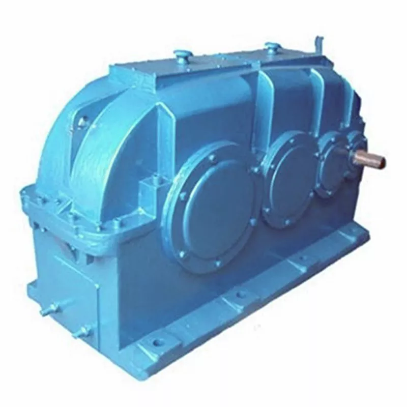
How do gear reducers contribute to speed reduction and torque increase?
Gear reducers play a crucial role in mechanical systems by achieving speed reduction and torque increase through the principle of gear ratios. Here's how they work:
Gear reducers consist of multiple gears with different sizes, known as gear pairs. These gears are meshed together, and their teeth interlock to transmit motion and power. The gear ratio is determined by the ratio of the number of teeth on the input gear (driver) to the number of teeth on the output gear (driven).
Speed Reduction: When a larger gear (output gear) is driven by a smaller gear (input gear), the output gear rotates at a slower speed than the input gear. This reduction in speed is proportional to the gear ratio. As a result, gear reducers are used to slow down the rotational speed of the output shaft compared to the input shaft.
Torque Increase: The interlocking teeth of gears create a mechanical advantage that allows gear reducers to increase torque output. When the input gear applies a force (torque) to the teeth, it is transmitted to the output gear with greater force due to the leverage provided by the larger diameter of the output gear. The torque increase is inversely proportional to the gear ratio and is essential for applications requiring high torque at lower speeds.
By selecting appropriate gear ratios and arranging gear pairs, gear reducers can achieve various speed reduction and torque multiplication factors, making them essential components in machinery and equipment where precise control of speed and torque is necessary.


editor by CX 2023-11-15
China best 88290001-129 Air Cylinder Hydraulic Cylinder for CZPT Screw Air Compressor vacuum pump engine
Product Description
Products Details
| Part Number | 88290001-129 |
| Type | Sullair Air Compressor Hydraulic Cylinder |
| Lead time | Around 7-15 days after receiving payment |
| Package | PP bag inside, inner carton, export carton outside. Or wooden box as your requirment |
Hot Products
Company Profile
ZheJiang CHINAMFG Machine Co., Ltd has the largest agent's qualification of CHINAMFG Asia Pte Ltd.
For more than 26 years, We have been provided professional compressed air energy-saving solution
for customers in China and abroad.
At the same time we have the spare parts warehouse of air compressors, like air filters, oil filters,
oil separator, lubricating oil, used air compressors, air end, motor etc.
World -famous brands such as Atlas Copco, CHINAMFG Rand air compressor accessories also available for us.
Certifications
Packaging & Shipping
FAQ
1.Why choose us?
We are Sullair's Chinese factory distributor, our price is very advantageous. And most of our products are in stocks, so we can delivery very fast.
2. How long is our delivery time?
Generally, we can ship within 3 days. If the product needs to be customized or the order quantity is large, it will take about 20 days.
3. What kind of spare parts we provide for?
We supply air compressor, air storage tank, pipeline filter, air dryer, nitrogen sparator, oxygen separator, compressed air pipeline, etc.
4. How long is the warranty of our products?
Whether it is a new machine or a second-hand air compressor machine, our warranty is 1 year.
5. What kind of after-sales service do we have?
We support 24-hour online free technical guidance.
| Customized: | Customized |
|---|---|
| Standard Component: | Standard Component |
| Material: | Stainless Steel |
| Category: | Intake Valve |
| Warranty: | 1 Year |
| Application: | Air Compressor |
| Samples: |
US$ 50/Piece
1 Piece(Min.Order) | |
|---|
| Customization: |
Available
|
|
|---|
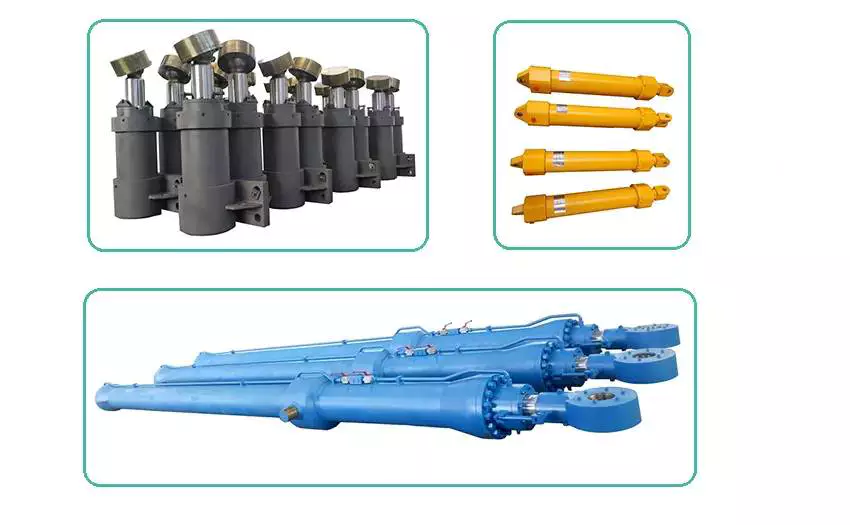
How do hydraulic cylinders compare to other methods of force generation like electric motors?
Hydraulic cylinders and electric motors are two different methods of force generation with distinct characteristics and applications. While both hydraulic cylinders and electric motors can generate force, they differ in terms of their working principles, performance attributes, and suitability for specific applications. Here's a detailed comparison of hydraulic cylinders and electric motors:
1. Working Principle:
- Hydraulic Cylinders: Hydraulic cylinders generate force through the conversion of fluid pressure into linear motion. They consist of a cylinder barrel, piston, piston rod, and hydraulic fluid. When pressurized hydraulic fluid enters the cylinder, it pushes against the piston, causing the piston rod to extend or retract, thereby generating linear force.
- Electric Motors: Electric motors generate force through the conversion of electrical energy into rotational motion. They consist of a stator, rotor, and electromagnetic field. When an electrical current is applied to the motor's windings, it creates a magnetic field that interacts with the rotor, causing it to rotate and generate torque.
2. Force and Power:
- Hydraulic Cylinders: Hydraulic cylinders are known for their high force capabilities. They can generate substantial linear forces, making them suitable for heavy-duty applications that require lifting, pushing, or pulling large loads. Hydraulic systems can provide high force output even at low speeds, allowing for precise control over force application. However, hydraulic systems typically operate at lower speeds compared to electric motors.
- Electric Motors: Electric motors excel in providing high rotational speeds and are commonly used for applications that require rapid motion. While electric motors can generate significant torque, they tend to have lower force output compared to hydraulic cylinders. Electric motors are suitable for applications that involve continuous rotary motion, such as driving conveyor belts, rotating machinery, or powering vehicles.
3. Control and Precision:
- Hydraulic Cylinders: Hydraulic systems offer excellent control over force, speed, and positioning. By regulating the flow of hydraulic fluid, the force and speed of hydraulic cylinders can be precisely controlled. Hydraulic systems can provide gradual acceleration and deceleration, allowing for smooth and precise movements. This level of control makes hydraulic cylinders well-suited for applications that require precise positioning, such as in industrial automation or construction equipment.
- Electric Motors: Electric motors also offer precise control over speed and positioning. Through motor control techniques such as varying voltage, frequency, or pulse width modulation (PWM), the rotational speed and position of electric motors can be accurately controlled. Electric motors are commonly used in applications that require precise speed control, such as robotics, CNC machines, or servo systems.
4. Efficiency and Energy Consumption:
- Hydraulic Cylinders: Hydraulic systems can be highly efficient, especially when properly sized and designed. However, hydraulic systems typically have higher energy losses due to factors such as fluid leakage, friction, and heat generation. The overall efficiency of a hydraulic system depends on the design, component selection, and maintenance practices. Hydraulic systems require a hydraulic power unit to pressurize the hydraulic fluid, which consumes additional energy.
- Electric Motors: Electric motors can have high efficiency, especially when operated at their optimal operating conditions. Electric motors have lower energy losses compared to hydraulic systems, primarily due to the absence of fluid leakage and lower friction losses. The overall efficiency of an electric motor depends on factors such as motor design, load conditions, and control techniques. Electric motors require an electrical power source, and their energy consumption depends on the motor's power rating and the duration of operation.
5. Environmental Considerations:
- Hydraulic Cylinders: Hydraulic systems typically use hydraulic fluids that can pose environmental concerns if they leak or are not properly disposed of. The choice of hydraulic fluid can impact factors such as biodegradability, toxicity, and potential environmental hazards. Proper maintenance and leak prevention practices are essential to minimize the environmental impact of hydraulic systems.
- Electric Motors: Electric motors are generally considered more environmentally friendly since they do not require hydraulic fluids. However, the environmental impact of electric motors depends on the source of electricity used to power them. When powered by renewable energy sources, such as solar or wind, electric motors can offer a greener solution compared to hydraulic systems.
6. Application Suitability:
- Hydraulic Cylinders: Hydraulic cylinders are commonly used in applications that require high force output, precise control, and durability. They are widely employed in industries such as construction, manufacturing, mining, and aerospace. Hydraulic systems are well-suited for heavy-duty applications, such as lifting heavy objects, operating heavy machinery, or controlling large-scale movements.
- Electric Motors: Electric motors are widely used in various industries and applications that require rotational motion, speed control, and precise positioning. They are commonly found in appliances, transportation, robotics, HVAC systems, and automation. Electric motorsare suitable for applications that involve continuous rotary motion, such as driving conveyor belts, rotating machinery, or powering vehicles.In summary, hydraulic cylinders and electric motors have different working principles, force capabilities, control characteristics, efficiency levels, and application suitability. Hydraulic cylinders excel in providing high force output, precise control, and durability, making them ideal for heavy-duty applications. Electric motors, on the other hand, offer high rotational speeds, precise speed control, and are commonly used for applications that involve continuous rotary motion. The choice between hydraulic cylinders and electric motors depends on the specific requirements of the application, including the type of motion, force output, control precision, and environmental considerations.
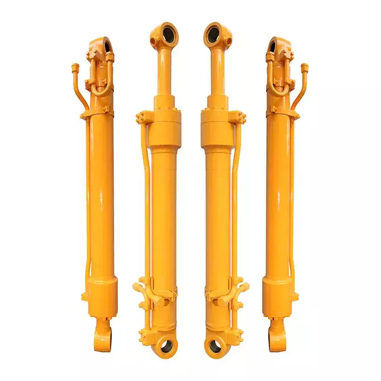
Utilizing Hydraulic Cylinders in Conjunction with Alternative Energy Sources
Hydraulic cylinders can indeed be used in conjunction with alternative energy sources. The versatile nature of hydraulic systems allows them to be integrated with various alternative energy technologies to enhance efficiency, control, and power generation. Let's explore some examples of how hydraulic cylinders can be utilized alongside alternative energy sources:
- Hydraulic Energy Storage: Hydraulic cylinders can be employed in energy storage systems that utilize alternative energy sources such as renewable sources (e.g., solar or wind) or waste energy recovery. These systems convert excess energy into hydraulic potential energy by pumping fluid into a high-pressure accumulator. When the energy is needed, the pressurized fluid is released, driving the hydraulic cylinder and generating mechanical power.
- Wave and Tidal Energy Conversion: Hydraulic cylinders can be utilized in wave and tidal energy conversion systems. These systems harness the power of ocean waves or tidal currents and convert it into usable energy. Hydraulic cylinders, along with associated pumps and valves, can be used to capture and control the energy from the waves or tides, driving the cylinders and generating mechanical power or producing electricity.
- Hydroelectric Power Generation: Hydraulic cylinders play a crucial role in traditional hydroelectric power generation. However, alternative approaches such as small-scale or micro-hydropower systems can also benefit from hydraulic cylinders. These systems utilize natural or man-made water flows to drive turbines connected to hydraulic cylinders, which then convert the hydraulic energy into mechanical power or electricity.
- Hydraulic Actuation in Wind Turbines: Hydraulic cylinders can be employed in wind turbines to enhance performance and control. For example, hydraulic pitch control systems use hydraulic cylinders to adjust the pitch angle of wind turbine blades, optimizing their aerodynamic performance based on wind conditions. This allows for efficient power generation and protection against excessive wind loads.
- Geothermal Energy Extraction: Geothermal energy extraction involves utilizing the natural heat from the Earth's interior to generate power. Hydraulic cylinders can be utilized in geothermal systems to control and regulate fluid flow, allowing for efficient extraction and utilization of geothermal energy. They can also be used in geothermal heat pumps for heating and cooling applications.
In summary, hydraulic cylinders can be effectively utilized in conjunction with alternative energy sources to enhance energy storage, power generation, and control. Whether it's through hydraulic energy storage systems, wave and tidal energy conversion, hydroelectric power generation, hydraulic actuation in wind turbines, or geothermal energy extraction, hydraulic cylinders offer versatile and efficient solutions for harnessing and utilizing alternative energy sources.
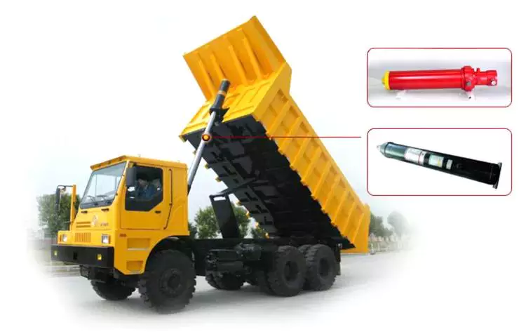
Can hydraulic cylinders be customized for specific equipment or attachment needs?
Yes, hydraulic cylinders can be customized to meet specific equipment or attachment needs. Hydraulic cylinder manufacturers often offer customization options to ensure that the cylinders meet the unique requirements of different applications. Here's a detailed explanation of how hydraulic cylinders can be customized for specific equipment or attachment needs:
1. Size and Configuration:
- Hydraulic cylinders can be customized in terms of size and configuration to fit specific equipment or attachment requirements. The dimensions of the cylinder, such as bore size, rod diameter, and stroke length, can be tailored to match the available space and the desired force or movement requirements. Additionally, the mounting style and orientation of the cylinder can be customized to ensure proper integration with the equipment or attachment.
2. Operating Pressure and Force:
- The operating pressure and force capabilities of hydraulic cylinders can be customized to suit the specific equipment or attachment needs. Different applications may require different force outputs, and hydraulic cylinder manufacturers can design and manufacture cylinders with the appropriate piston area and pressure ratings to meet those requirements. Customization in this aspect ensures optimal performance and efficiency for the particular equipment or attachment.
3. Stroke Length:
- The stroke length of a hydraulic cylinder refers to the distance the piston can travel from fully retracted to fully extended. Customization of the stroke length allows the hydraulic cylinder to accommodate the specific range of motion required by the equipment or attachment. By adjusting the stroke length, the cylinder can be tailored to deliver the necessary extension and retraction capabilities for efficient operation.
4. Mounting Options:
- Hydraulic cylinders can be customized with various mounting options to facilitate easy installation and integration with specific equipment or attachments. Different applications may require different mounting styles, such as flange mounts, trunnion mounts, or clevis mounts. Manufacturers can provide customized mounting options to ensure proper alignment, stability, and functionality when the cylinder is connected to the equipment or attachment.
5. Sealing and Material Options:
- The sealing system of a hydraulic cylinder is crucial for preventing fluid leakage and maintaining the cylinder's integrity. Hydraulic cylinder manufacturers offer customization options for sealing materials, such as different types of seals and seal configurations, to suit specific equipment or attachment needs. Additionally, customization of cylinder materials, such as selecting corrosion-resistant materials or specialized coatings, can enhance the cylinder's durability and performance in specific operating environments.
6. Integration with Control Systems:
- In certain applications, hydraulic cylinders may need to be integrated with sophisticated control systems or automation technologies. Customization can involve incorporating sensors, position feedback devices, or other control elements into the hydraulic cylinder design to enable seamless integration with the overall equipment or attachment control system. This customization ensures precise control, monitoring, and synchronization of the hydraulic cylinder's movements within the specific application.
7. Specialized Features or Accessories:
- Hydraulic cylinder customization can also involve incorporating specialized features or accessories to meet unique equipment or attachment needs. This may include the integration of safety features, such as pressure relief valves or load-holding valves, or the addition of specific ports or fittings for auxiliary functions or attachments. Customization allows hydraulic cylinders to be tailored to the specific requirements and functionalities of the equipment or attachment.
By offering customization options, hydraulic cylinder manufacturers can provide solutions that precisely match the needs of different equipment or attachment applications. Customized hydraulic cylinders ensure optimal performance, efficiency, and integration, enhancing the overall functionality and productivity of the equipment or attachment. It is important to work closely with experienced manufacturers or hydraulic system specialists to determine the specific customization requirements and ensure the successful implementation of customized hydraulic cylinders.


editor by CX 2023-11-03
China Standard Customized Double Screw Barrel Gearbox for Granule Production with Good quality
Product Description
Overview
Product Description
Wide Selection of Gearbox Products
The gearbox usually adopts a general design scheme, but in special cases, the design scheme of the gearbox can be changed according to the demands of the user, and it can be modified into an industry-specific gearbox. In the design scheme of the gearbox, the parallel shaft, vertical shaft, general box, and various parts can be changed
Advantages
- Absorption of very high torques and axial forces
- No need for separate thrust housing & bearing.
- Easy alignment (screw directly fits into the vore of gear box)
- Easy to assemble & dismantle.
- Very heavy duty spherical roller thrust bearing is provided.
- Power saving. (you may save up to 20 % power.)
- Less requirement of space.
- For bigger sizes water cooling is provided
- No maintenance required except periodic oil level checking.
- Higher productivity
Features
- Twin Screw Extruder Gearboxes offer the dual shaft counter rotating. The range is available for various center distances
- The gearboxes are available with co-rotating and counter rotating variants
- To work under heavy loading force, the high level dissipation and oil lubrication system are provided. The axial roller type swivel thrust with the thrust bearing coupled in tandem way support the axial thrust
- High torque and high speed output rate
Processing Characteristics of Screw Shaft:
1.Suitable suggestion on material to ensure components performance and extend lifetime of products.
2.Professional technical team can provide surveying and mapping support.
3.All components are finished by CNC machine.
4.Sophisticated quality management system ensure superior quality.
Basic Info.
| Warranty: 1 year | Weight (KG): 500 KG |
| Place of Origin: HangZhou, China |
Gearing Arrangement: helical |
| ratio: 8-20 |
Output Torque: 2*176 |
| standard: JB/T8853-2001 |
Certificate: CE |
| Heat treatment: High-frequency Hardening |
Efficiency: 94%~98%(depends on the transmission stage) |
| Customized support:OEM ODM | Input/output shaft material 40Cr |
| Package: Wooden case |
Mount position: Flange, hollow shaft, CHINAMFG shaft |
| After-sale:Online 24/7 Installation Xihu (West Lake) Dis. | advantage: excellent quality |
| Reduction radio: 3:1 |
Mount Position: Horizontal Foot Mounted Vertical |
| Input Speed: 1500 |
Output Speed: 500 |
Packaging & delivery
|
Packing: wooden case packing |
|
| Port: HangZhou Port |
Applications
X helical gear units for double-screw extruders with parallel drive shafts and the same direction of screw rotation are used mainly in the manufacture of granulates and the refining of raw plastics. Other areas of application include:
- Paint and lacquer industry
- Washing agent industry
- Foodstuff industry (e.g. bread, pasta)
- Animal-feed industry (dog, cat other animal food
Maintenance of the gearbox of the dual-screw extruder
1. The gear box of the dual-screw extruder should be well-ventilated, and the working environment temperature should be within the range of 5-35 °C.
2. Always check the oil quantity of the gear lubricating oil in the box to ensure that the transmission parts in the box are well lubricated.
3. Pay attention to check the bearing parts of the box frequently. The oil temperature of the oil tank of the transmission box should not exceed 70 ºC during operation.
4. The newly put into use gearbox needs to replace the lubricating oil after 250 hours of operation. The oil change time depends on the state of the oil. It is recommended to replace it after 4000-8000 hours of operation or once a year.
5. The gearbox of the dual-screw extruder needs to be regularly maintained and inspected once a year
Operating Process
1. The gear on the input shaft is driven by the motor and starts to rotate.
2. The rotating input gear meshes with other gears inside the gearbox, transmitting power.
3. Different-sized gears within the gearbox are combined to form a gear train. Through continuous meshing and rotation, the high-speed, low-torque power from the input shaft gradually converts into low-speed, high-torque output.
4. The output shaft is connected to the last gear and transfers the output torque to the load.
5. Gear reduction gearboxes typically include lubrication and cooling systems to ensure smooth operation and prevent overheating and damage.
6. Our extruder gearbox converts high-speed, low-torque power into low-speed, high-torque output by changing the size ratios and meshing arrangements of different gears, achieving the function of speed reduction.
Types of Gearboxes:
Based on customer requirements, gear reduction gearboxes can be classified according to the size of the output shaft, center distance of the output shaft, output speed, and torque. Alternatively, we can provide several commonly used types of gearboxes for customers to choose from.
Product Service
|
24-hour Hotline
No matter when and where to call we can find our service to you.
|
Pre-sales Consultation
We have 5 sales people online, and whether you have any question can be solved through online communication. |
After-sales Services
Receive products have any questions about the product, can look for us,we will help you deal with the the first time,to your satisfaction. |
Exhibition
Certificate
Company profile
ZheJiang Arrow Machinery Co., Ltd.is a company specializing in R&D, production, sales, application promotion of food engineering projects. As 1 of the largest scaled food processing equipment &whole plant engineering problem solvers in China, machines served for more than 970 companies, export to 116 countries, area, more than 20 years engineering team, we recognize that quality equals value, aims to create a great future together with global customers.
FAQ
1. Q: How about Arrow Machinery?
R: ZheJiang Arrow Machinery Co., Ltd. is a High-Tech company. Our firm is composed of a strong
team which has substantial experience in R&D, manufacture, technique and sales service and has
specialized in extruder industry for 10 years,leading screw barrel manufacturer in China.
2. Q:What's Arrow machinery's capacity?
R:Company is in strict accordance with CE and ISO9001 quality certification system.There are over 200
models of extruders and spare parts.
3. Q:What's the delivery time?
R:For regular size, we have finished stock and semi-finished stock, 2 weeks max enough
for customized, normally within 20days .
4. Q:How about the gearbox quality and price?
R: top quality in China with competitive price and globle after-sale service
5. Q:what's the life time and guarantee buy from Arrow machinery ?
R: 3~5years life time for nitriding ones and bimtallic ones will be longer
One year min. Guarantee.
6.Q:Where is Arrow Machinery factory and how to reach there?
R:NO.47 Chengbohu Road, Xihu (West Lake) Dis. District,HangZhou City, China. You can take the train or plane to HangZhou and we can pick you up.
7.Q:How to contact with you?
R:just reply to me if have any question.
|
Shipping Cost:
Estimated freight per unit. |
To be negotiated |
|---|
| Application: | Motor, Machinery |
|---|---|
| Function: | Distribution Power, Change Drive Torque, Change Drive Direction, Speed Changing, Speed Reduction, Speed Increase |
| Layout: | Coaxial |
| Samples: |
US$ 3600/Piece
1 Piece(Min.Order) | Order Sample |
|---|
| Customization: |
Available
| Customized Request |
|---|
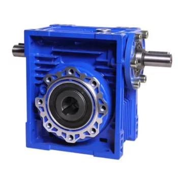
Can a Worm Gearbox be Used for High-Speed Applications?
Worm gearboxes are generally not recommended for high-speed applications due to their inherent design characteristics. Here's why:
- Efficiency: Worm gearboxes tend to have lower efficiency compared to other gearbox types, which means they can generate more heat and experience more energy loss at high speeds.
- Heat Generation: The sliding contact between the worm and worm wheel in a worm gearbox can lead to significant friction and heat generation, especially at high speeds. This heat can cause thermal expansion, affecting the gearbox's performance and longevity.
- Wear and Noise: High speeds can exacerbate wear and noise issues in worm gearboxes. Increased friction and wear can lead to faster degradation of components, resulting in reduced lifespan and increased maintenance needs.
- Backlash: Worm gearboxes may have higher backlash compared to other gearbox types, which can impact precision and accuracy in high-speed applications.
While worm gearboxes are more commonly used in applications requiring high torque and moderate speeds, they may not be the best choice for high-speed scenarios. If high-speed operation is a requirement, other gearbox types such as helical, spur, or planetary gearboxes are often better suited due to their higher efficiency, lower heat generation, and reduced wear at elevated speeds.
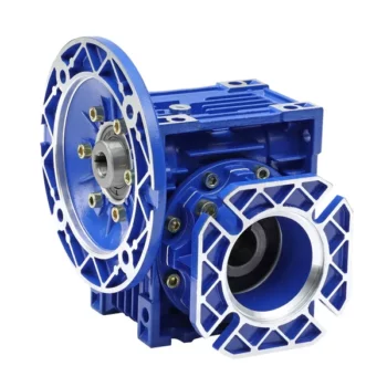
How to Calculate the Input and Output Speeds of a Worm Gearbox?
Calculating the input and output speeds of a worm gearbox involves understanding the gear ratio and the principles of gear reduction. Here's how you can calculate these speeds:
- Input Speed: The input speed (N1) is the speed of the driving gear, which is the worm gear in this case. It is usually provided by the manufacturer or can be measured directly.
- Output Speed: The output speed (N2) is the speed of the driven gear, which is the worm wheel. To calculate the output speed, use the formula:
N2 = N1 / (Z1 * i)
Where:
N2 = Output speed (rpm)
N1 = Input speed (rpm)
Z1 = Number of teeth on the worm gear
i = Gear ratio (ratio of the number of teeth on the worm gear to the number of threads on the worm)
It's important to note that worm gearboxes are designed for gear reduction, which means that the output speed is lower than the input speed. Additionally, the efficiency of the gearbox, friction, and other factors can affect the actual output speed. Calculating the input and output speeds is crucial for understanding the performance and capabilities of the worm gearbox in a specific application.
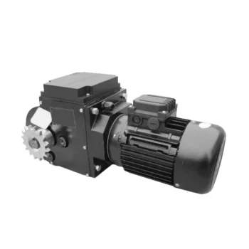
Lubrication Requirements for a Worm Gearbox
Lubrication is crucial for maintaining the performance and longevity of a worm gearbox. Here are the key considerations for lubricating a worm gearbox:
- Type of Lubricant: Use a high-quality, high-viscosity lubricant specifically designed for worm gearboxes. Worm gearboxes require lubricants with additives that provide proper lubrication and prevent wear.
- Lubrication Interval: Follow the manufacturer's recommendations for lubrication intervals. Regularly check the gearbox's temperature and oil condition to determine the optimal frequency of lubrication.
- Oil Level: Maintain the proper oil level to ensure effective lubrication. Too little oil can lead to insufficient lubrication, while too much oil can cause overheating and foaming.
- Lubrication Points: Identify all the lubrication points on the gearbox, including the worm and wheel gear surfaces. Apply the lubricant evenly to ensure complete coverage.
- Temperature: Consider the operating temperature of the gearbox. Some lubricants have temperature limits, and extreme temperatures can affect lubricant viscosity and performance.
- Cleanliness: Keep the gearbox and the surrounding area clean to prevent contaminants from entering the lubricant. Use proper filtration and seals to maintain a clean environment.
- Monitoring: Regularly monitor the gearbox's temperature, noise level, and vibration to detect any signs of inadequate lubrication or other issues.
Proper lubrication will reduce friction, wear, and heat generation, ensuring smooth and efficient operation of the worm gearbox. Always refer to the manufacturer's guidelines for lubrication specifications and intervals.


editor by CX 2023-09-18
China Good quality CZPT Arrow Type Znfpy-42 Gearbox for Twin Screw Extruder bevel gearbox
Product Description
Overview
Product Description
Wide Selection of Gearbox Products
The gearbox usually adopts a general design scheme, but in special cases, the design scheme of the gearbox can be changed according to the demands of the user, and it can be modified into an industry-specific gearbox. In the design scheme of the gearbox, the parallel shaft, vertical shaft, general box, and various parts can be changed
Advantages
- Absorption of very high torques and axial forces
- No need for separate thrust housing & bearing.
- Easy alignment (screw directly fits into the vore of gear box)
- Easy to assemble & dismantle.
- Very heavy duty spherical roller thrust bearing is provided.
- Power saving. (you may save up to 20 % power.)
- Less requirement of space.
- For bigger sizes water cooling is provided
- No maintenance required except periodic oil level checking.
- Higher productivity
Features
- Twin Screw Extruder Gearboxes offer the dual shaft counter rotating. The range is available for various center distances
- The gearboxes are available with co-rotating and counter rotating variants
- To work under heavy loading force, the high level dissipation and oil lubrication system are provided. The axial roller type swivel thrust with the thrust bearing coupled in tandem way support the axial thrust
- High torque and high speed output rate
Processing Characteristics of Screw Shaft:
1.Suitable suggestion on material to ensure components performance and extend lifetime of products.
2.Professional technical team can provide surveying and mapping support.
3.All components are finished by CNC machine.
4.Sophisticated quality management system ensure superior quality.
Basic Info.
| Warranty: 1 year | Weight (KG): 500 KG |
| Place of Origin: HangZhou, China |
Gearing Arrangement: helical |
| ratio: 8-20 |
Output Torque: 2*176 |
| standard: JB/T8853-2001 |
Certificate: CE |
| Heat treatment: High-frequency Hardening |
Efficiency: 94%~98%(depends on the transmission stage) |
| Customized support:OEM ODM | Input/output shaft material 40Cr |
| Package: Wooden case |
Mount position: Flange, hollow shaft, CHINAMFG shaft |
| After-sale:Online 24/7 Installation Xihu (West Lake) Dis. | advantage: excellent quality |
| Reduction radio: 3:1 |
Mount Position: Horizontal Foot Mounted Vertical |
| Input Speed: 1500 |
Output Speed: 500 |
Packaging & delivery
|
Packing: wooden case packing |
|
| Port: HangZhou Port |
Applications
X helical gear units for double-screw extruders with parallel drive shafts and the same direction of screw rotation are used mainly in the manufacture of granulates and the refining of raw plastics. Other areas of application include:
- Paint and lacquer industry
- Washing agent industry
- Foodstuff industry (e.g. bread, pasta)
- Animal-feed industry (dog, cat other animal food
Maintenance of the gearbox of the dual-screw extruder
1. The gear box of the dual-screw extruder should be well-ventilated, and the working environment temperature should be within the range of 5-35 °C.
2. Always check the oil quantity of the gear lubricating oil in the box to ensure that the transmission parts in the box are well lubricated.
3. Pay attention to check the bearing parts of the box frequently. The oil temperature of the oil tank of the transmission box should not exceed 70 ºC during operation.
4. The newly put into use gearbox needs to replace the lubricating oil after 250 hours of operation. The oil change time depends on the state of the oil. It is recommended to replace it after 4000-8000 hours of operation or once a year.
5. The gearbox of the dual-screw extruder needs to be regularly maintained and inspected once a year
Operating Process
1. The gear on the input shaft is driven by the motor and starts to rotate.
2. The rotating input gear meshes with other gears inside the gearbox, transmitting power.
3. Different-sized gears within the gearbox are combined to form a gear train. Through continuous meshing and rotation, the high-speed, low-torque power from the input shaft gradually converts into low-speed, high-torque output.
4. The output shaft is connected to the last gear and transfers the output torque to the load.
5. Gear reduction gearboxes typically include lubrication and cooling systems to ensure smooth operation and prevent overheating and damage.
6. Our extruder gearbox converts high-speed, low-torque power into low-speed, high-torque output by changing the size ratios and meshing arrangements of different gears, achieving the function of speed reduction.
Types of Gearboxes:
Based on customer requirements, gear reduction gearboxes can be classified according to the size of the output shaft, center distance of the output shaft, output speed, and torque. Alternatively, we can provide several commonly used types of gearboxes for customers to choose from.
Product Service
|
24-hour Hotline
No matter when and where to call we can find our service to you.
|
Pre-sales Consultation
We have 5 sales people online, and whether you have any question can be solved through online communication. |
After-sales Services
Receive products have any questions about the product, can look for us,we will help you deal with the the first time,to your satisfaction. |
Exhibition
Certificate
Company profile
ZheJiang Arrow Machinery Co., Ltd.is a company specializing in R&D, production, sales, application promotion of food engineering projects. As 1 of the largest scaled food processing equipment &whole plant engineering problem solvers in China, machines served for more than 970 companies, export to 116 countries, area, more than 20 years engineering team, we recognize that quality equals value, aims to create a great future together with global customers.
FAQ
1. Q: How about Arrow Machinery?
R: ZheJiang Arrow Machinery Co., Ltd. is a High-Tech company. Our firm is composed of a strong
team which has substantial experience in R&D, manufacture, technique and sales service and has
specialized in extruder industry for 10 years,leading screw barrel manufacturer in China.
2. Q:What's Arrow machinery's capacity?
R:Company is in strict accordance with CE and ISO9001 quality certification system.There are over 200
models of extruders and spare parts.
3. Q:What's the delivery time?
R:For regular size, we have finished stock and semi-finished stock, 2 weeks max enough
for customized, normally within 20days .
4. Q:How about the gearbox quality and price?
R: top quality in China with competitive price and globle after-sale service
5. Q:what's the life time and guarantee buy from Arrow machinery ?
R: 3~5years life time for nitriding ones and bimtallic ones will be longer
One year min. Guarantee.
6.Q:Where is Arrow Machinery factory and how to reach there?
R:NO.47 Chengbohu Road, Xihu (West Lake) Dis. District,HangZhou City, China. You can take the train or plane to HangZhou and we can pick you up.
7.Q:How to contact with you?
R:just reply to me if have any question.
|
Shipping Cost:
Estimated freight per unit. |
To be negotiated |
|---|
| Application: | Motor, Machinery |
|---|---|
| Function: | Distribution Power, Change Drive Torque, Change Drive Direction, Speed Changing, Speed Reduction, Speed Increase |
| Layout: | Cycloidal |
| Customization: |
Available
| Customized Request |
|---|

Self-Locking Properties in a Worm Gearbox
Yes, worm gearboxes exhibit self-locking properties, which can be advantageous in certain applications. Self-locking refers to the ability of a mechanism to prevent the transmission of motion from the output shaft back to the input shaft when the system is at rest. Worm gearboxes inherently possess self-locking properties due to the unique design of the worm gear and worm wheel.
The self-locking behavior arises from the angle of the helix on the worm shaft. In a properly designed worm gearbox, the helix angle of the worm is such that it creates a mechanical advantage that resists reverse motion. When the gearbox is not actively driven, the friction between the worm threads and the worm wheel teeth creates a locking effect.
This self-locking feature makes worm gearboxes particularly useful in applications where holding a load in position without external power is necessary. For instance, they are commonly used in situations where there's a need to prevent a mechanism from backdriving, such as in conveyor systems, hoists, and jacks.
However, it's important to note that while self-locking properties can be beneficial, they also introduce some challenges. The high friction between the worm gear and worm wheel during self-locking can lead to higher wear and heat generation. Additionally, the self-locking effect can reduce the efficiency of the gearbox when it's actively transmitting motion.
When considering the use of a worm gearbox for a specific application, it's crucial to carefully analyze the balance between self-locking capabilities and other performance factors to ensure optimal operation.
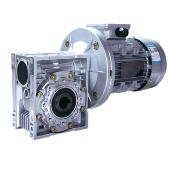
Does a Worm Reducer Require Frequent Maintenance?
Worm reducers generally require less frequent maintenance compared to some other types of gearboxes due to their design and operating characteristics. However, maintenance is still essential to ensure optimal performance and longevity. Here are some key points to consider:
- Lubrication: Proper lubrication is crucial for worm gearboxes. Regularly check the lubricant level and quality to prevent wear and overheating. Lubricant should be changed as recommended by the manufacturer.
- Inspections: Periodically inspect the gearbox for signs of wear, damage, or oil leaks. Check for any unusual noises, vibrations, or changes in performance that could indicate a problem.
- Tightening and Alignment: Check and tighten any loose fasteners and ensure that the gearbox is properly aligned. Misalignment can lead to increased wear and reduced efficiency.
- Seal Maintenance: Inspect and maintain seals to prevent oil leakage and contaminants from entering the gearbox.
- Cleaning: Keep the gearbox clean from debris and contaminants that could affect its performance. Regular cleaning can prevent premature wear and damage.
- Load and Speed: Ensure that the gearbox is operating within its rated load and speed limits. Exceeding these limits can lead to accelerated wear and potential failure.
- Environmental Conditions: Consider the operating environment of the gearbox. Extreme temperatures, humidity, and other factors can impact the gearbox's performance and longevity.
While worm gearboxes are known for their durability and self-locking feature, neglecting maintenance can lead to premature wear, reduced efficiency, and potential breakdowns. Following the manufacturer's recommendations for maintenance intervals and procedures is essential to keep the worm reducer in optimal condition.
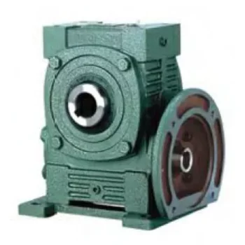
How to Select the Right Worm Gearbox for Your Application
Selecting the right worm gearbox for your application involves careful consideration of various factors:
- Load Requirements: Determine the torque and load requirements of your application to ensure the selected gearbox can handle the load without compromising performance.
- Speed Reduction: Calculate the required gear reduction ratio to achieve the desired output speed. Worm gearboxes are known for high reduction ratios.
- Efficiency: Consider the gearbox's efficiency, as worm gearboxes typically have lower efficiency due to the sliding action. Evaluate whether the efficiency meets your application's needs.
- Space Constraints: Assess the available space for the gearbox. Worm gearboxes have a compact design, making them suitable for applications with limited space.
- Mounting Options: Determine the mounting orientation and configuration that best suits your application.
- Operating Environment: Consider factors such as temperature, humidity, and exposure to contaminants. Choose a gearbox with appropriate seals and materials to withstand the environment.
- Backlash: Evaluate the acceptable level of backlash in your application. Worm gearboxes may exhibit more backlash compared to other gear types.
- Self-Locking: If self-locking capability is required, confirm that the selected gearbox can prevent reverse motion without the need for external braking mechanisms.
- Maintenance: Consider the maintenance requirements of the gearbox. Some worm gearboxes require periodic lubrication and maintenance to ensure proper functioning.
- Cost: Balance the features and performance of the gearbox with the overall cost to ensure it aligns with your budget.
Consult with gearbox manufacturers or experts to get recommendations tailored to your specific application. Testing and simulations can also help validate the suitability of a particular gearbox for your needs.


editor by CX 2023-09-15