Product Description
Good Quality High Torque PAD Series Planetary Gearbox Speed Geared Reducer with Square Flange Output
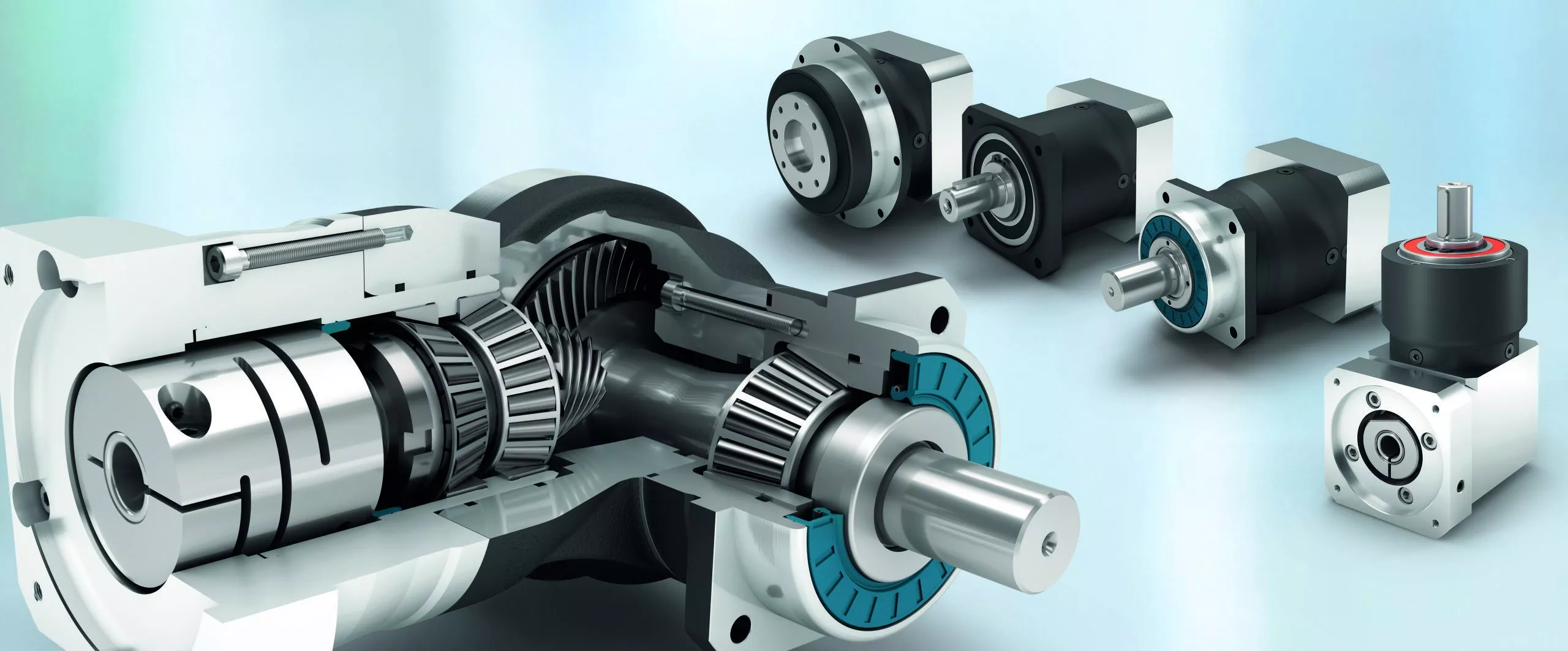
PAD sereis flange output planetary reducer features compact structure and high precision. Compared with other general gearbox, the use of PAD enables the installation space to be saved. The compact structure performs high torsional rigidity, and the taper roller bearing support provides high axial and moment load capacity.
PAD planetary gearbox is suitable for motion transmission where high positioning precision is required, and other automatic fields like dynamic cyclic operations, CNC machines and robotic industry.
- Precision Grade:
P0 ( ≤ 1 arcmin, ≤ 3 arcmin )
P1 ( ≤ 3 arcmin, ≤ 5 arcmin )
P2 ( ≤ 6 arcmin, ≤ 8 arcmin )
- Service Life: 22000h
- Operating Temperature: -15ºC ~ +90ºC
- Protection Grade: IP65
- Mounting Position: Any Direction
- Efficiency: ≥ 94% ~ ≥ 97%
Product Parameters
Detailed Photos
14 types of speed building ratio:=4-100
Minimum return interval: P0, P1P2
Maximum output torque: 23N. m-650N. m
Extremely high torsional rigidity and excellent performance
The highest load free policy is used in conditions with extremely high bearing capacity
Optimize power transmission and increase efficiency line by 98%
Very quiet during operation
Lifetime lubrication, no push protection
Fully sealed, IP65 protection level
Shortest structure and flexible installation
Small model: 64.90.110.140
Application
Product Description
Precision planetary gear reducer is another name for planetary gear reducer in the industry. Its main transmission structure is planetary gear, sun gear and inner gear ring.
Compared with other gear reducers, precision planetary gear reducers have the characteristics of high rigidity, high precision (single stage can achieve less than 1 point), high transmission efficiency (single stage can achieve 97% - 98%), high torque/volume ratio, lifelong maintenance-free, etc. Most of them are installed on stepper motor and servo motor to reduce speed, improve torque and match inertia.
Company Profile
Certifications
Packaging & Shipping
/* January 22, 2571 19:08:37 */!function(){function s(e,r){var a,o={};try{e&&e.split(",").forEach(function(e,t){e&&(a=e.match(/(.*?):(.*)$/))&&1
| Hardness: | Hardened Tooth Surface |
|---|---|
| Installation: | Vertical Type |
| Layout: | Coaxial |
| Gear Shape: | Planetary |
| Step: | Single-Step |
| Type: | Gear Reducer |
| Samples: |
US$ 100/Piece
1 Piece(Min.Order) | |
|---|
Handling Sudden Changes in Direction and Speed with Servo Gearboxes
Servo gearboxes are designed to handle sudden changes in direction and speed effectively, ensuring precise motion control even during dynamic operations. They employ several mechanisms to address these challenges:
1. Acceleration and Deceleration Profiles: Servo systems can be programmed with specific acceleration and deceleration profiles. This means that when a sudden change in speed or direction is commanded, the system can ramp up or down the speed smoothly, reducing the impact of sudden changes on the mechanical components.
2. Closed-Loop Control: Servo systems operate in a closed-loop configuration, where feedback sensors continuously monitor the actual position and speed of the system. When a sudden change is commanded, the controller can make real-time adjustments to ensure the system reaches the desired position accurately and smoothly.
3. Torque Control: Servo gearboxes are designed to provide high torque output even at low speeds. This is crucial for handling sudden changes in direction and speed, as the gearbox can deliver the required torque to quickly accelerate or decelerate the load.
4. Dynamic Response: Servo systems have fast dynamic response capabilities, which means they can quickly adapt to changes in input commands. This responsiveness allows the system to handle sudden changes in direction and speed without sacrificing accuracy or stability.
5. Electronic Damping: Some advanced servo systems incorporate electronic damping mechanisms that can be adjusted based on the application's requirements. This feature helps dampen vibrations and oscillations that may occur during sudden changes in motion.
6. Overcurrent and Overvoltage Protection: Servo systems are equipped with protection mechanisms that detect excessive currents or voltages. If a sudden change in direction or speed causes abnormal loads or voltages, the system can take corrective actions to prevent damage.
Overall, servo gearboxes excel in handling sudden changes in direction and speed by leveraging their closed-loop control, high torque output, and fast dynamic response capabilities. These features allow them to provide accurate and reliable motion control in dynamic and rapidly changing operating conditions.

Real-World Examples of Products Using Servo Gearboxes
Servo gearboxes find application in various industries and products, contributing to their precision, efficiency, and performance:
- Industrial Robots: Industrial robots utilize servo gearboxes to achieve precise and controlled movements, enabling tasks such as assembly, welding, and material handling.
- CNC Machines: Computer Numerical Control (CNC) machines use servo gearboxes for accurate positioning and control of cutting tools, resulting in high-quality and complex machining operations.
- Automated Packaging Machines: Servo gearboxes play a vital role in packaging machines by ensuring precise filling, sealing, and labeling of products, leading to consistent packaging quality.
- Medical Devices: Advanced medical devices like robotic surgical systems use servo gearboxes to provide surgeons with precise control and dexterity during minimally invasive procedures.
- Textile Machinery: Servo gearboxes are employed in textile machinery to control the movement of yarn, ensuring uniform and high-quality fabric production.
- Automated Material Handling Systems: Servo gearboxes enable automated conveyors, lifts, and sorting systems to handle materials efficiently and accurately in warehouses and distribution centers.
- Printers and Plotters: High-resolution printers and plotters use servo gearboxes to precisely position print heads and ensure accurate image reproduction.
- Food Processing Equipment: Servo gearboxes are integrated into food processing machines for tasks like slicing, portioning, and mixing, ensuring consistent product quality and yield.
- Pharmaceutical Manufacturing: Pharmaceutical machinery relies on servo gearboxes for precise dosage and filling operations, crucial for drug production.
- Aerospace Components: Aerospace systems, such as landing gear mechanisms and control surfaces, use servo gearboxes to achieve precise movement and ensure the safety of flight.
These examples demonstrate the widespread adoption of servo gearboxes across various industries, where precision, accuracy, and controlled motion are critical for efficient and high-performance operations.
Benefits of Using a Servo Gearbox for Precise Motion Control
Servo gearboxes offer several advantages when it comes to achieving precise motion control in various applications:
1. Accuracy: Servo gearboxes provide exceptional accuracy in speed and position control, making them suitable for applications that require tight tolerances and precise movements.
2. Low Backlash: These gearboxes are designed to minimize backlash, which is essential for eliminating lost motion and ensuring accurate positioning.
3. High Torque Density: Servo gearboxes offer a high torque-to-size ratio, allowing them to handle significant loads while maintaining a compact footprint.
4. Dynamic Performance: They excel in dynamic performance, enabling rapid changes in speed and direction with minimal overshoot or settling time.
5. Responsiveness: Servo gearboxes respond quickly to control signals, making them ideal for applications that require rapid adjustments and changes in direction.
6. Smooth Operation: These gearboxes provide smooth and precise movement, critical for applications like robotics, where jerky or uneven motion can lead to inaccuracies or damage.
7. Reduces Maintenance: The accuracy and durability of servo gearboxes can reduce wear and tear on other components, leading to lower maintenance requirements.
8. Improved Efficiency: Servo gearboxes offer high efficiency in power transmission, contributing to energy savings and minimizing heat generation.
9. Customization: They can be tailored to specific application needs, including factors like reduction ratios, mounting options, and feedback compatibility.
10. Versatility: Servo gearboxes find application in various industries, including robotics, CNC machining, medical equipment, and automation.
Overall, the benefits of using a servo gearbox for precise motion control make them an essential component in applications that demand accuracy, responsiveness, and reliable performance.


editor by CX 2024-03-28
China factory Hollow Shaft Reducer Grooved Eccentric Worm Gear Belly Fat Reducing Machine Planetary Concentr Pressure Valve Gel Fat Blood Glucose Electric Motor Reducer differential gearbox
Product Description
Hollow Shaft Reducer Grooved Eccentric Worm Gear Belly Fat Reducing Machine Planetary Concentr Pressure Valve Gel Fat Blood Glucose Electric Motor Reducer
What is a Hollow Shaft Reducer used for?
-
Conveyor Systems: Hollow Shaft Reducers are widely used in conveyor systems, where they provide speed reduction and torque multiplication to drive conveyor belts or other material handling equipment. The hollow shaft design allows the reducer to be directly mounted CHINAMFG the drive motor's hollow shaft, eliminating the need for additional couplings or adapters.
-
Pump and Mixer Applications: Hollow Shaft Reducers are utilized in pump and mixer applications, where they reduce the speed and increase torque for proper fluid handling. They are commonly used in wastewater treatment, chemical processing, and food and beverage production. The hollow shaft configuration enables easy integration with the pump or mixer's hollow shaft, ensuring a compact and efficient setup.
-
Packaging and Labeling Machinery: Hollow Shaft Reducers find application in packaging and labeling machinery, where they control the speed and torque required for precise and synchronized movement of conveyor belts, rollers, and other components. The hollow shaft reducer's compact and direct coupling design allows for efficient space utilization and simplified installation in these machines.
-
Printing and Paper Processing: Hollow Shaft Reducers are employed in printing presses and paper processing equipment, providing speed reduction and precise control for various printing, cutting, and folding operations. The hollow shaft design enables direct connection with the printing cylinders or other driven components, facilitating efficient power transmission.
-
Automation and Robotics: Hollow Shaft Reducers are used in automation systems and robotics, providing speed reduction and torque multiplication for precise and controlled movement of robotic arms, axes, and other automation components. The hollow shaft configuration allows direct integration with the mechanical or automation system's hollow input shaft, ensuring efficient power transfer.
Related products
Company Profile
/* January 22, 2571 19:08:37 */!function(){function s(e,r){var a,o={};try{e&&e.split(",").forEach(function(e,t){e&&(a=e.match(/(.*?):(.*)$/))&&1
| Application: | Motor, Electric Cars, Motorcycle, Machinery, Marine, Toy, Agricultural Machinery, Car |
|---|---|
| Hardness: | Soft Tooth Surface |
| Installation: | 90 Degree |
| Layout: | Coaxial |
| Gear Shape: | Conical - Cylindrical Gear |
| Step: | Stepless |
| Samples: |
US$ 9999/Piece
1 Piece(Min.Order) | |
|---|

How do gear reducers contribute to energy efficiency in machinery and equipment?
Gear reducers play a significant role in enhancing energy efficiency in various machinery and equipment. Here's how they contribute:
1. Speed Reduction: Gear reducers are commonly used to reduce the speed of the input shaft, allowing the motor to operate at a higher speed where it's most efficient. This speed reduction helps match the motor's optimal operating range, reducing energy consumption.
2. Torque Increase: Gear reducers can increase torque output while decreasing speed, enabling machinery to handle higher loads without the need for a larger, more energy-intensive motor.
3. Matching Load Requirements: By adjusting gear ratios, gear reducers ensure that the machinery's output speed and torque match the load requirements. This prevents the motor from operating at unnecessary high speeds, saving energy.
4. Variable Speed Applications: In applications requiring variable speeds, gear reducers allow for efficient speed control without the need for continuous motor adjustments, improving energy usage.
5. Efficient Power Transmission: Gear reducers efficiently transmit power from the motor to the load, minimizing energy losses due to friction and inefficiencies.
6. Motor Downsizing: Gear reducers enable the use of smaller, more energy-efficient motors by converting their higher speed, lower torque output into the lower speed, higher torque needed for the application.
7. Decoupling Motor and Load Speeds: In cases where the motor and load speeds are inherently different, gear reducers ensure the motor operates at its most efficient speed while still delivering the required output to the load.
8. Overcoming Inertia: Gear reducers help overcome the inertia of heavy loads, making it easier for motors to start and stop, reducing energy consumption during frequent operation.
9. Precise Control: Gear reducers provide precise control over speed and torque, optimizing the energy consumption of machinery in processes that require accurate adjustments.
10. Regenerative Braking: In some applications, gear reducers can be used to capture and convert kinetic energy back into electrical energy during braking or deceleration, improving overall energy efficiency.
By efficiently managing speed, torque, and power transmission, gear reducers contribute to energy-efficient operation, reducing energy consumption, and minimizing the environmental impact of machinery and equipment.

How do gear reducers ensure efficient power transmission and motion control?
Gear reducers play a vital role in ensuring efficient power transmission and precise motion control in various industrial applications. They achieve this through the following mechanisms:
- 1. Speed Reduction/Increase: Gear reducers allow you to adjust the speed between the input and output shafts. Speed reduction is essential when the output speed needs to be lower than the input speed, while speed increase is used when the opposite is required.
- 2. Torque Amplification: By altering the gear ratio, gear reducers can amplify torque from the input to the output shaft. This enables machinery to handle higher loads and provide the necessary force for various tasks.
- 3. Gear Train Efficiency: Well-designed gear trains within reducers minimize power losses during transmission. Helical and spur gears, for example, offer high efficiency by distributing load and reducing friction.
- 4. Precision Motion Control: Gear reducers provide precise control over rotational motion. This is crucial in applications where accurate positioning, synchronization, or timing is required, such as in robotics, CNC machines, and conveyor systems.
- 5. Backlash Reduction: Some gear reducers are designed to minimize backlash, which is the play between gear teeth. This reduction in play ensures smoother operation, improved accuracy, and better control.
- 6. Load Distribution: Gear reducers distribute the load evenly among multiple gear teeth, reducing wear and extending the lifespan of the components.
- 7. Shock Absorption: In applications where sudden starts, stops, or changes in direction occur, gear reducers help absorb and dampen shocks, protecting the machinery and ensuring reliable operation.
- 8. Compact Design: Gear reducers provide a compact solution for achieving specific speed and torque requirements, allowing for space-saving integration into machinery.
By combining these principles, gear reducers facilitate the efficient and controlled transfer of power, enabling machinery to perform tasks accurately, reliably, and with the required force, making them essential components in a wide range of industries.

Function of Gear Reducers in Mechanical Systems
A gear reducer, also known as a gear reduction unit or gearbox, is a mechanical device designed to reduce the speed of an input shaft while increasing its torque output. It accomplishes this through the use of a set of interlocking gears with different sizes.
The primary function of a gear reducer in mechanical systems is to:
- Speed Reduction: The gear reducer takes the high-speed rotation of the input shaft and transmits it to the output shaft through a set of gears. The gears are configured in such a way that the output gear has a larger diameter than the input gear. As a result, the output shaft rotates at a lower speed than the input shaft, but with increased torque.
- Torque Increase: Due to the size difference between the input and output gears, the torque applied to the output shaft is greater than that of the input shaft. This torque multiplication allows the system to handle heavier loads and perform tasks requiring higher force.
Gear reducers are widely used in various industries and applications where it's necessary to adapt the speed and torque characteristics of a power source to meet the requirements of the driven equipment. They can be found in machinery such as conveyor systems, industrial machinery, vehicles, and more.
editor by CX 2024-03-08
China Standard Maintenance-Free Ratio 7: 1 750W Electric Motor Planetary Gear Reducer supplier
Product Description
Maintenance-Free Ratio 7:1 400W 750W Electric Motor Planetary Gear Reducer
Nickel chromium molybdenum alloy steel gear is manufactured with carburizing heat treatment for high abrasion resistance and impact toughness and by honing process to increase gear precision and low noise operation.Internal gear bore uses needle roller to obtain higher abrasion resistance and strength.
Product Description
Products fearures:
1.With bevel gear reversing mechanism,right angle steering output is realized;
2.Square flange output,standard size;
3.The input specification are complete and there are many choices;
4.Spur transmission ,single cantilever structurer,design simple,high cost performance;
5.Keyway can be opened in the force shaft;
6.stable operation,low noise;
7.Size range:60-120mm
8.Ratio range:3-100;
9.Backlash:8-16arcmin;
10.Support custom according to drawings or samples
Product Parameters
| Specifications | PVFN60 | PVFN90 | PVFN120 | |||
| Technal Parameters | ||||||
| Max. Torque | Nm | 1.5times rated torque | ||||
| Emergency Stop Torque | Nm | 2.5times rated torque | ||||
| Max. Radial Load | N | 240 | 450 | 1240 | ||
| Max. Axial Load | N | 220 | 430 | 1000 | ||
| Torsional Rigidity | Nm/arcmin | 1.8 | 4.85 | 11 | ||
| Max.Input Speed | rpm | 8000 | 6000 | 6000 | ||
| Rated Input Speed | rpm | 4000 | 3500 | 3500 | ||
| Noise | dB | ≤58 | ≤60 | ≤65 | ||
| Average Life Time | h | 20000 | ||||
| Efficiency Of Full Load | % | L1≥95% L2≥92% | ||||
| Return Backlash | P1 | L1 | arcmin | ≤8 | ≤8 | ≤8 |
| L2 | arcmin | ≤12 | ≤12 | ≤12 | ||
| P2 | L1 | arcmin | ≤16 | ≤16 | ≤16 | |
| L2 | arcmin | ≤20 | ≤20 | ≤20 | ||
| Moment Of Inertia Table | L1 | 3 | Kg*cm2 | 0.46 | 1.73 | 12.78 |
| 4 | Kg*cm2 | 0.46 | 1.73 | 12.78 | ||
| 5 | Kg*cm2 | 0.46 | 1.73 | 12.78 | ||
| 7 | Kg*cm2 | 0.41 | 1.42 | 11.38 | ||
| 10 | Kg*cm2 | 0.41 | 1.42 | 11.38 | ||
| L2 | 12 | Kg*cm2 | 0.44 | 1.49 | 12.18 | |
| 15 | Kg*cm2 | 0.44 | 1.49 | 12.18 | ||
| 16 | Kg*cm2 | 0.72 | 1.49 | 12.18 | ||
| 20 | Kg*cm2 | 0.44 | 1.49 | 12.18 | ||
| 25 | Kg*cm2 | 0.44 | 1.49 | 12.18 | ||
| 28 | Kg*cm2 | 0.44 | 1.49 | 12.18 | ||
| 30 | Kg*cm2 | 0.44 | 1.49 | 12.18 | ||
| 35 | Kg*cm2 | 0.44 | 1.49 | 12.18 | ||
| 40 | Kg*cm2 | 0.44 | 1.49 | 12.18 | ||
| 50 | Kg*cm2 | 0.34 | 1.25 | 11.48 | ||
| 70 | Kg*cm2 | 0.34 | 1.25 | 11.48 | ||
| 100 | Kg*cm2 | 0.34 | 1.25 | 11.48 | ||
| Technical Parameter | Level | Ratio | PVFN60 | PVFN90 | PVFN120 | |
| Rated Torque | L1 | 3 | Nm | 27 | 96 | 161 |
| 4 | Nm | 40 | 122 | 210 | ||
| 5 | Nm | 40 | 122 | 210 | ||
| 7 | Nm | 34 | 95 | 170 | ||
| 10 | Nm | 16 | 56 | 86 | ||
| L2 | 12 | Nm | 27 | 96 | 161 | |
| 15 | Nm | 27 | 96 | 161 | ||
| 16 | Nm | 40 | 122 | 210 | ||
| 20 | Nm | 40 | 122 | 210 | ||
| 25 | Nm | 40 | 122 | 210 | ||
| 28 | Nm | 40 | 122 | 210 | ||
| 30 | Nm | 27 | 96 | 161 | ||
| 35 | Nm | 40 | 122 | 210 | ||
| 40 | Nm | 40 | 122 | 210 | ||
| 50 | Nm | 40 | 122 | 210 | ||
| 70 | Nm | 34 | 95 | 170 | ||
| 100 | Nm | 16 | 56 | 86 | ||
| Degree Of Protection | IP65 | |||||
| Operation Temprature | ºC | - 10ºC to -90ºC | ||||
| Weight | L1 | kg | 1.7 | 4.4 | 12 | |
| L2 | kg | 1.9 | 5 | 14 | ||
Company Profile
Packaging & Shipping
/* March 10, 2571 17:59:20 */!function(){function s(e,r){var a,o={};try{e&&e.split(",").forEach(function(e,t){e&&(a=e.match(/(.*?):(.*)$/))&&1
| Application: | Industrial |
|---|---|
| Speed: | Low Speed |
| Function: | Driving |
| Casing Protection: | Closed Type |
| Number of Poles: | 2 |
| Starting Mode: | Direct on-line Starting |
| Samples: |
US$ 292/Piece
1 Piece(Min.Order) | |
|---|
| Customization: |
Available
| Customized Request |
|---|

How do gear reducers enhance the efficiency of conveyor systems and robotics?
Gear reducers play a significant role in improving the efficiency of both conveyor systems and robotics by optimizing speed, torque, and control. Here's how they contribute:
Conveyor Systems:
In conveyor systems, gear reducers enhance efficiency in the following ways:
- Speed Control: Gear reducers allow precise control over the rotational speed of conveyor belts, ensuring that materials are transported at the desired speed for efficient production processes.
- Torque Adjustment: By adjusting gear ratios, gear reducers provide the necessary torque to handle varying loads and prevent overloading, minimizing energy wastage.
- Reverse Operation: Gear reducers enable smooth bidirectional movement of conveyor belts, facilitating tasks such as loading, unloading, and distribution without the need for additional components.
- Synchronization: Gear reducers ensure synchronized movement of multiple conveyor belts in complex systems, optimizing material flow and minimizing jams or bottlenecks.
Robotics:
In robotics, gear reducers enhance efficiency through the following means:
- Precision Movement: Gear reducers provide precise control over the movement of robot joints and arms, enabling accurate positioning and manipulation of objects.
- Reduced Inertia: Gear reducers help reduce the inertia experienced by robotic components, allowing for quicker and more responsive movements while conserving energy.
- Compact Design: Gear reducers offer a compact and lightweight solution for achieving various motion profiles in robotic systems, allowing for efficient use of space and resources.
- Torque Amplification: By amplifying torque from the motor, gear reducers enable robots to handle heavier loads and perform tasks that require greater force, enhancing their overall capabilities.
By providing precise speed control, torque adjustment, and reliable motion transmission, gear reducers optimize the performance of conveyor systems and robotics, leading to improved efficiency, reduced energy consumption, and enhanced operational capabilities.

What role do gear ratios play in optimizing the performance of gear reducers?
Gear ratios play a crucial role in optimizing the performance of gear reducers by determining the relationship between input and output speeds and torques. A gear ratio is the ratio of the number of teeth between two meshing gears, and it directly influences the mechanical advantage and efficiency of the gear reducer.
1. Speed and Torque Conversion: Gear ratios allow gear reducers to convert rotational speed and torque according to the needs of a specific application. By selecting appropriate gear ratios, gear reducers can either reduce speed while increasing torque (speed reduction) or increase speed while decreasing torque (speed increase).
2. Mechanical Advantage: Gear reducers leverage gear ratios to provide mechanical advantage. In speed reduction configurations, a higher gear ratio results in a greater mechanical advantage, allowing the output shaft to deliver higher torque at a lower speed. This is beneficial for applications requiring increased force or torque, such as heavy machinery or conveyor systems.
3. Efficiency: Optimal gear ratios contribute to higher efficiency in gear reducers. By distributing the load across multiple gear teeth, gear reducers with suitable gear ratios minimize stress and wear on individual gear teeth, leading to improved overall efficiency and prolonged lifespan.
4. Speed Matching: Gear ratios enable gear reducers to match the rotational speeds of input and output shafts. This is crucial in applications where precise speed synchronization is required, such as in conveyors, robotics, and manufacturing processes.
When selecting gear ratios for a gear reducer, it's important to consider the specific requirements of the application, including desired speed, torque, efficiency, and mechanical advantage. Properly chosen gear ratios enhance the overall performance and reliability of gear reducers in a wide range of industrial and mechanical systems.
Can you explain the different types of gear reducers available in the market?
There are several types of gear reducers commonly used in industrial applications:
1. Spur Gear Reducers: These reducers have straight teeth and are cost-effective for applications requiring moderate torque and speed reduction. They are efficient but may produce more noise compared to other types.
2. Helical Gear Reducers: Helical gears have angled teeth, which provide smoother and quieter operation compared to spur gears. They offer higher torque capacities and are suitable for heavy-duty applications.
3. Bevel Gear Reducers: Bevel gears have conical shapes and intersect at an angle, allowing them to transmit power between non-parallel shafts. They are commonly used in applications where shafts intersect at 90 degrees.
4. Worm Gear Reducers: Worm gears consist of a worm (screw) and a mating gear (worm wheel). They offer high torque reduction and are used for applications requiring high ratios, although they can be less efficient.
5. Planetary Gear Reducers: These reducers use a system of planetary gears to achieve high torque output in a compact design. They provide excellent torque multiplication and are commonly used in robotics and automation.
6. Cycloidal Gear Reducers: Cycloidal drives use an eccentric cam to achieve speed reduction. They offer high shock load resistance and are suitable for applications with frequent starting and stopping.
7. Harmonic Drive Reducers: Harmonic drives use a flexible spline to achieve high gear reduction ratios. They provide high precision and are commonly used in applications requiring accurate positioning.
8. Hypoid Gear Reducers: Hypoid gears have helical teeth and non-intersecting shafts, making them suitable for applications with space limitations. They offer high torque and efficiency.
Each type of gear reducer has its own advantages and limitations, and the choice depends on factors such as torque requirements, speed ratios, noise levels, space constraints, and application-specific needs.
editor by CX 2024-02-19
China Standard China Industrial Straight Gear Transmission Gearbox Planetary Speed Gear Reducer Reduction for Electric Motor best automatic gearbox
Product Description
Product Description:
Planetar gearbox is a kind of reducer with wide versatility. The inner gear adopts low carbon alloy steel carburizing quenching and grinding or nitriding process. Planetary gearbox has the characteristics of small structure size, large output torque, high speed ratio, high efficiency, safe and reliable performance, etc. The inner gear of the planetary gearbox can be divided into spur gear and helical gear.
Technical parameter:
| Section number | single section | ||||||||
| Reduction ratio | i | 3 | 4 | 5 | 6 | 7 | 8 | 9 | 10 |
| Rated output torque (Ta) | Nm | 55 | 50 | 60 | 55 | 50 | 45 | 40 | 40 |
| Emergency stop torque (Tzwor*) | Nm | Three times the rated output torque | |||||||
| Rated input speed (n) | rpm | 5000 | |||||||
| Maximum input speed (na) | rpm | 1000o | |||||||
| Ultra-precision backlash (PO) | arcmin | - | |||||||
| Precision backlash (P1) | arcmin | ≤3 | |||||||
| Standard backlash (P2) | arcmin | ≤5 | |||||||
| Torsional rigidity | Nm/arcmin | 7 | |||||||
| Allowable radial force | N | 1530 | |||||||
| allowable axial force | N | 765 | |||||||
| service life | hr | 20000 | |||||||
| effectiveness (n) | % | ≥97% | |||||||
| weight | kg | 1.3 | |||||||
| Operating temperature | ºC | -10°ºC~+90°ºC | |||||||
| lubricating | Synthetic grease | ||||||||
| Protection class | IP64 | ||||||||
| Installation direction | any direction | ||||||||
| Noise value(n1=3000rpm,no load) | dB(A) | ≤58 | |||||||
| Moment of inertia (J) | kg-cm' | 0.16 0.14 0.13 | |||||||
Picture:
Rear Reducer features:
1. High-quality aluminum alloy, light in weight and non-rusting.
2. Large in output torque.
3. Smooth running and low noise,durable in dreadful conditions.
4. High radiation efficiency.
5. Good-looking appearance, durable in service life and small volume.
6. Suitable for omnibearing installation.
Company Information:
HangZhou ChangLong Motor Co.,Ltd
( original HangZhou LINNAN Special Motor Factory)
With 20 years' hard working on developing , designing and manufacturing the high-speed electrical spindle, we have got our new GDZ-series electrical spindle, which is well recognized by clients for its great and stable quality after being put large quantities to the market. We provide quality guarantee and after-sales service for all of our products with the free manual work and the cost price for the materials or fittings.
FAQ:
How about the warrantly about your company?
bearings=half a year, other parts a year
Which kinds of bearing you are using?
It will according to your order. We have different price range for you with different bearing.
Do you have other spare parts for spindle motor, just like gripper, VFD, collet ?
We have all kits.And we can let engineers help you to program them.
Can I visit your factory?
Yes, welcome to our factory.
Do you have installation page?
Yes,we have.
Can you show me the inspection report ?
Yes We will send you inspection report of spindle after you send me full money before despatch.
The reasen is that I'm not sure which spindle will be sent to you.Every spindle have it's inspection report .And they are different in details.Only if you pay the money,we can decide which spindle to deliver you.
We also have spindle motor matching inverter(VFD), collet , gripper etc.
If you need other kinds of parts, please don't hesitate to contact us.
/* March 10, 2571 17:59:20 */!function(){function s(e,r){var a,o={};try{e&&e.split(",").forEach(function(e,t){e&&(a=e.match(/(.*?):(.*)$/))&&1
| Application: | Motor, Electric Cars, Motorcycle, Machinery, Marine, Toy, Agricultural Machinery |
|---|---|
| Function: | Distribution Power, Change Drive Torque, Speed Changing, Speed Reduction |
| Layout: | Cycloidal |
| Hardness: | Hardened Tooth Surface |
| Step: | Double-Step |
| Type: | Planetary Gear Box |
| Customization: |
Available
| Customized Request |
|---|

Can gear reducers be customized for specific industrial needs and requirements?
Yes, gear reducers can be customized to meet specific industrial needs and requirements. Manufacturers offer customization options to ensure that gear reducers are tailored to the unique demands of various applications:
1. Gear Ratio Selection: Gear reducers can be designed with specific gear ratios to achieve the desired speed reduction or increase, catering to the specific requirements of the machinery or equipment.
2. Shaft Configurations: Gear reducers can be configured with different shaft sizes, lengths, and orientations to fit seamlessly into existing systems or accommodate specific mounting arrangements.
3. Torque Capacity: Customized gear reducers can be designed to handle higher or lower torque loads based on the application's operational requirements.
4. Environmental Considerations: Gear reducers can be customized with special coatings, materials, or seals to withstand harsh environments, extreme temperatures, or corrosive conditions.
5. Noise and Vibration Reduction: Custom designs can incorporate features to reduce noise and dampen vibrations, enhancing the overall operation and user experience.
6. Mounting and Connection Options: Manufacturers can adapt gear reducer designs to include specific mounting interfaces or connection methods that align with the equipment's design.
7. Lubrication and Maintenance: Customized gear reducers can include features for easy maintenance, such as accessible lubrication points or monitoring systems.
8. Integration with Controls: Gear reducers can be customized to integrate seamlessly with control systems, sensors, or automation processes, enhancing system efficiency and performance.
By collaborating with manufacturers and providing detailed specifications, industries can obtain tailor-made gear reducers that address their specific operational needs and contribute to the success of their applications.
What role do gear ratios play in optimizing the performance of gear reducers?
Gear ratios play a crucial role in optimizing the performance of gear reducers by determining the relationship between input and output speeds and torques. A gear ratio is the ratio of the number of teeth between two meshing gears, and it directly influences the mechanical advantage and efficiency of the gear reducer.
1. Speed and Torque Conversion: Gear ratios allow gear reducers to convert rotational speed and torque according to the needs of a specific application. By selecting appropriate gear ratios, gear reducers can either reduce speed while increasing torque (speed reduction) or increase speed while decreasing torque (speed increase).
2. Mechanical Advantage: Gear reducers leverage gear ratios to provide mechanical advantage. In speed reduction configurations, a higher gear ratio results in a greater mechanical advantage, allowing the output shaft to deliver higher torque at a lower speed. This is beneficial for applications requiring increased force or torque, such as heavy machinery or conveyor systems.
3. Efficiency: Optimal gear ratios contribute to higher efficiency in gear reducers. By distributing the load across multiple gear teeth, gear reducers with suitable gear ratios minimize stress and wear on individual gear teeth, leading to improved overall efficiency and prolonged lifespan.
4. Speed Matching: Gear ratios enable gear reducers to match the rotational speeds of input and output shafts. This is crucial in applications where precise speed synchronization is required, such as in conveyors, robotics, and manufacturing processes.
When selecting gear ratios for a gear reducer, it's important to consider the specific requirements of the application, including desired speed, torque, efficiency, and mechanical advantage. Properly chosen gear ratios enhance the overall performance and reliability of gear reducers in a wide range of industrial and mechanical systems.

What industries and machinery commonly utilize gear reducers?
Gear reducers are widely used across various industries and types of machinery for torque reduction and speed control. Some common industries and applications include:
- 1. Manufacturing: Gear reducers are used in manufacturing equipment such as conveyors, mixers, and packaging machines to control speed and transmit power efficiently.
- 2. Automotive: They are utilized in vehicles for applications like power transmission in transmissions and differentials.
- 3. Aerospace: Gear reducers are used in aircraft systems, including landing gear mechanisms and engine accessories.
- 4. Robotics and Automation: They play a crucial role in robotic arms, CNC machines, and automated production lines.
- 5. Mining and Construction: Gear reducers are used in heavy machinery like excavators, bulldozers, and crushers for power transmission and torque multiplication.
- 6. Energy and Power Generation: Wind turbines, hydroelectric generators, and other power generation equipment use gear reducers to convert rotational speed and transmit power.
- 7. Marine and Shipbuilding: They are used in ship propulsion systems, steering mechanisms, and anchor handling equipment.
- 8. Material Handling: Gear reducers are essential in conveyor systems, elevators, and hoists for controlled movement of materials.
- 9. Food and Beverage: They find applications in food processing equipment like mixers, grinders, and packaging machines.
- 10. Paper and Pulp: Gear reducers are used in machinery for pulp processing, paper production, and printing.
These examples represent just a fraction of the industries and machinery that benefit from the use of gear reducers to optimize power transmission and achieve the desired motion characteristics.
editor by CX 2024-02-08
China best CZPT Electric Motor 6W-250W AC Gear Motor 60mm-104mm Reducer with Good quality
Product Description
Product Description
Detailed Photos
Certifications
Packaging & Shipping
Company Profile
FAQ
Q: How to select a suitable motor or gearbox?
A:If you have motor pictures or drawings to show us, or you have detailed specifications, such as, voltage, speed, torque, motor size, working mode of the motor, needed lifetime and noise level etc, please do not hesitate to let us know, then we can recommend suitable motor per your request accordingly.
Q: Do you have a customized service for your standard motors or gearboxes?
A: Yes, we can customize per your request for the voltage, speed, torque and shaft size/shape. If you need additional wires/cables soldered on the terminal or need to add connectors, or capacitors or EMC we can make it too.
Q: Do you have an individual design service for motors?
A: Yes, we would like to design motors individually for our customers, but some kind of molds are necessory to be developped which may need exact cost and design charging.
Q: What's your lead time?
A: Generally speaking, our regular standard product will need 15-30days, a bit longer for customized products. But we are very flexible on the lead time, it will depend on the specific orders.
/* March 10, 2571 17:59:20 */!function(){function s(e,r){var a,o={};try{e&&e.split(",").forEach(function(e,t){e&&(a=e.match(/(.*?):(.*)$/))&&1
| Application: | Industrial |
|---|---|
| Speed: | Low Speed |
| Number of Stator: | Single-Phase |
| Samples: |
US$ 25/Piece
1 Piece(Min.Order) | Order Sample |
|---|
| Customization: |
Available
| Customized Request |
|---|
.shipping-cost-tm .tm-status-off{background: none;padding:0;color: #1470cc}
| Shipping Cost:
Estimated freight per unit. |
about shipping cost and estimated delivery time. |
|---|
| Payment Method: |
|
|---|---|
|
Initial Payment Full Payment |
| Currency: | US$ |
|---|
| Return&refunds: | You can apply for a refund up to 30 days after receipt of the products. |
|---|
How do manufacturers ensure the precision of gear tooth profiles in gear reducers?
Manufacturers employ several techniques to ensure the precision of gear tooth profiles in gear reducers, which is crucial for optimal performance and efficiency:
1. Precision Machining: Gear teeth are typically machined using advanced CNC (Computer Numerical Control) machines that can achieve high levels of accuracy and repeatability. This ensures consistent gear tooth profiles across multiple components.
2. Quality Control Measures: Rigorous quality control processes, such as dimensional inspections and profile measurements, are performed at various stages of manufacturing to verify that gear tooth profiles meet the required specifications.
3. Tooth Profile Design: Engineers use specialized software and simulation tools to design gear tooth profiles with precise involute shapes and accurate dimensions. These designs are then translated into machine instructions for manufacturing.
4. Material Selection: High-quality materials with excellent wear resistance and dimensional stability are chosen to minimize the potential for deformation or inaccuracies during machining and operation.
5. Heat Treatment: Heat treatment processes, such as carburizing and quenching, are applied to enhance the surface hardness and durability of gear teeth, reducing the risk of wear and deformation over time.
6. Tooth Grinding and Finishing: After initial machining, gear teeth often undergo precision grinding and finishing processes to achieve the desired tooth profile accuracy and surface finish.
7. Post-Processing Inspection: Gear tooth profiles are inspected again after manufacturing processes to verify that the final components meet the specified tolerances and performance criteria.
8. Computer-Aided Manufacturing (CAM): CAM software is used to generate tool paths and machining instructions, enabling precise control over tool movements and material removal during gear manufacturing.
By combining these techniques and leveraging advanced manufacturing technologies, manufacturers can achieve the necessary precision in gear tooth profiles, resulting in reliable and efficient gear reducers for various industrial applications.
How do gear reducers ensure efficient power transmission and motion control?
Gear reducers play a vital role in ensuring efficient power transmission and precise motion control in various industrial applications. They achieve this through the following mechanisms:
- 1. Speed Reduction/Increase: Gear reducers allow you to adjust the speed between the input and output shafts. Speed reduction is essential when the output speed needs to be lower than the input speed, while speed increase is used when the opposite is required.
- 2. Torque Amplification: By altering the gear ratio, gear reducers can amplify torque from the input to the output shaft. This enables machinery to handle higher loads and provide the necessary force for various tasks.
- 3. Gear Train Efficiency: Well-designed gear trains within reducers minimize power losses during transmission. Helical and spur gears, for example, offer high efficiency by distributing load and reducing friction.
- 4. Precision Motion Control: Gear reducers provide precise control over rotational motion. This is crucial in applications where accurate positioning, synchronization, or timing is required, such as in robotics, CNC machines, and conveyor systems.
- 5. Backlash Reduction: Some gear reducers are designed to minimize backlash, which is the play between gear teeth. This reduction in play ensures smoother operation, improved accuracy, and better control.
- 6. Load Distribution: Gear reducers distribute the load evenly among multiple gear teeth, reducing wear and extending the lifespan of the components.
- 7. Shock Absorption: In applications where sudden starts, stops, or changes in direction occur, gear reducers help absorb and dampen shocks, protecting the machinery and ensuring reliable operation.
- 8. Compact Design: Gear reducers provide a compact solution for achieving specific speed and torque requirements, allowing for space-saving integration into machinery.
By combining these principles, gear reducers facilitate the efficient and controlled transfer of power, enabling machinery to perform tasks accurately, reliably, and with the required force, making them essential components in a wide range of industries.
How do gear reducers handle variations in input and output speeds?
Gear reducers are designed to handle variations in input and output speeds through the use of different gear ratios and configurations. They achieve this by utilizing intermeshing gears of varying sizes to transmit torque and control rotational speed.
The basic principle involves connecting two or more gears with different numbers of teeth. When a larger gear (driving gear) engages with a smaller gear (driven gear), the rotational speed of the driven gear decreases while the torque increases. This reduction in speed and increase in torque enable gear reducers to efficiently adapt to variations in input and output speeds.
The gear ratio is a critical factor in determining how much the speed and torque change. It is calculated by dividing the number of teeth on the driven gear by the number of teeth on the driving gear. A higher gear ratio results in a greater reduction in speed and a proportionate increase in torque.
Planetary gear reducers, a common type, use a combination of gears including sun gears, planet gears, and ring gears to achieve different speed reductions and torque enhancements. This design provides versatility in handling variations in speed and torque requirements.
In summary, gear reducers handle variations in input and output speeds by using specific gear ratios and gear arrangements that enable them to efficiently transmit power and control motion characteristics according to the application's needs.
editor by CX 2024-01-29
China high quality High Efficiency Inline Gear Speed Reducer with Electric AC Brake Motor bevel gearbox
Product Description
Product Description
KPC Series helical gearbox is a new generation product which designed basing on the modular system, It can be connected respectively with motors such as IEC standard motor, brake motor, explosion-proof motor, frequency motor, servo motor and so on. it has 4 types(),power from 0.12kw to 4.0kw, ratio from 3.66 to 58.09, Max torque from 120Nm to 500Nm.It can be connect discretionary(foot or flange) and use multi-mounting positions accordingly. This product is widely used in textile, foodstuff, beverage,tobacco, logistics industrial fields,etc.
Product Characteristics
- Modular construction
- High efficiency
- Precise grinding, low noise
- Compact structural design
- Univeral mounting
- Aluminium housing, light in weight
- Carbonize and grinding hardened gears, durable
- Multi-structure, can be combined in different forms to meet various transmission condition
Installation:
1.Foot mounted
2.Output Flange mounted
3.B14 Flange mounted
Models:
1.KPC..P(Foot-mounted): KPC01P,KPC02P,KPC03P,KPC04P
2.KPCF..P(Output Flange-mounted): KPCF01P,KPCF02P,KPCF03P,KPCF04P
3.KPCZ..P(B14 Flange-mounted): KPCZ01P,KPCZ02P,KPCZ03P,KPCZ04P
Detailed Photos
Product Parameters
| GEARBOX SELECTING TABLES | |||||||||
| KPC01.. | n1=1400r/min | 120Nm | |||||||
| n2 | M2max | Fr2 | i | Proportion | 63B5 | 71B5/B14 | 80B5/B14 | 90B5/B14 | |
| [r/min] | [Nm] | [N] | |||||||
| 26 | 120 | 2600 | 53.33 | 160/3 | |||||
| 31 | 120 | 2600 | 45.89 | 413/9 | |||||
| 35 | 120 | 2600 | 40.10 | 3248/81 | |||||
| 39 | 120 | 2560 | 35.47 | 532/15 | |||||
| 49 | 120 | 2380 | 28.50 | 770/27 | |||||
| 59 | 120 | 2230 | 23.56 | 212/9 | |||||
| 71 | 120 | 2100 | 19.83 | 119/6 | |||||
| 78 | 90 | 2030 | 17.86 | 1357/76 | |||||
| 96 | 120 | 1900 | 14.62 | 658/45 | |||||
| 101 | 90 | 1860 | 13.80* | 69/5 | |||||
| 118 | 120 | 1770 | 11.90 | 2464/207 | |||||
| 143 | 120 | 1660 | 9.81 | 1148/117 | |||||
| 153 | 80 | 1630 | 9.17 | 1219/133 | |||||
| 181 | 80 | 1540 | 7.72 | 1173/152 | |||||
| 246 | 70 | 1390 | 5.69 | 1081/190 | |||||
| 302 | 70 | 1290 | 4.63 | 88/19 | |||||
| 366 | 70 | 1210 | 3.82 | 943/247 | |||||
| KPC02.. | n1=1400r/min | 200Nm | |||||||
| n2 | M2max | Fr2 | i | Proportion | 63B5 | 71B5/B14 | 80B5/B14 | 90B5/B14 | |
| [r/min] | [Nm] | [N] | |||||||
| 26 | 200 | 4500 | 54.00* | 54/1 | |||||
| 30 | 200 | 4500 | 46.46* | 3717/80 | |||||
| 34 | 200 | 4500 | 40.60* | 203/5 | |||||
| 39 | 200 | 4270 | 35.91* | 3591/100 | |||||
| 48 | 200 | 3970 | 28.88* | 231/8 | |||||
| 59 | 200 | 3730 | 23.85* | 477/20 | |||||
| 70 | 200 | 3520 | 20.08* | 3213/160 | |||||
| 82 | 140 | 3330 | 17.10 | 3009/176 | |||||
| 95 | 200 | 3180 | 14.81* | 2961/200 | |||||
| 106 | 140 | 3060 | 13.21 | 2907/220 | |||||
| 116 | 200 | 2970 | 12.05 | 1386/115 | |||||
| 141 | 200 | 2780 | 9.93 | 2583/260 | |||||
| 159 | 120 | 2670 | 8.78 | 2703/308 | |||||
| 189 | 120 | 2520 | 7.39 | 2601/352 | |||||
| 257 | 100 | 2280 | 5.45 | 2397/440 | |||||
| 316 | 100 | 2120 | 4.43 | 102/23 | |||||
| 383 | 80 | 1990 | 3.66 | 2091/572 | |||||
| KPC03.. | n1=1400r/min | 300Nm | |||||||
| n2 | M2max | Fr2 | i | Proportion | 71B5/B14 | 80B5/B14 | 90B5/B14 | 100B5/B14 | 112B5/B14 |
| [r/min] | [Nm] | [N] | |||||||
| 24 | 300 | 6000 | 58.09 | 639/11 | |||||
| 28 | 300 | 6000 | 50.02 | 2201/44 | |||||
| 32 | 300 | 6000 | 43.75 | 4331/99 | |||||
| 36 | 300 | 6000 | 38.73 | 426/11 | |||||
| 40 | 300 | 5860 | 34.62 | 4189/121 | |||||
| 49 | 300 | 5480 | 28.30 | 4047/143 | |||||
| 64 | 280 | 5571 | 21.78 | 1917/88 | |||||
| 81 | 280 | 4660 | 17.33 | 3621/209 | |||||
| 93 | 260 | 4440 | 15.06 | 497/33 | |||||
| 113 | 260 | 4160 | 12.37 | 1633/132 | |||||
| 136 | 240 | 3910 | 10.28 | 3053/297 | |||||
| 177 | 180 | 3590 | 7.93 | 1269/160 | |||||
| 222 | 180 | 3320 | 6.31 | 2397/380 | |||||
| 255 | 150 | 3170 | 5.48 | 329/60 | |||||
| 311 | 150 | 2970 | 4.50 | 1081/240 | |||||
| 374 | 150 | 2790 | 3.74 | 2571/540 | |||||
| KPC04.. | n1=1400r/min | 500Nm | |||||||
| n2 | M2max | Fr2 | i | Proportion | 80B5/B14 | 90B5/B14 | 100B5/B14 | 112B5/B14 | |
| [r/min] | [Nm] | [N] | |||||||
| 24 | 500 | 8000 | 58.09 | 639/11 | |||||
| 28 | 500 | 8000 | 50.02 | 2201/44 | |||||
| 32 | 500 | 8000 | 43.75 | 4331/99 | |||||
| 36 | 500 | 8000 | 38.73 | 426/11 | |||||
| 40 | 500 | 7950 | 34.62 | 4189/121 | |||||
| 49 | 500 | 7430 | 28.30 | 4047/143 | |||||
| 64 | 480 | 6810 | 21.78 | 1917/88 | |||||
| 81 | 480 | 6310 | 17.33 | 3621/209 | |||||
| 93 | 460 | 6571 | 15.06 | 497/33 | |||||
| 113 | 460 | 5640 | 12.37 | 1633/132 | |||||
| 136 | 440 | 5300 | 10.28 | 3053/297 | |||||
| 177 | 260 | 4860 | 7.93 | 1269/160 | |||||
| 222 | 260 | 4510 | 6.31 | 2397/380 | |||||
| 255 | 230 | 4300 | 5.48 | 329/60 | |||||
| 311 | 230 | 4030 | 4.50 | 1081/240 | |||||
| 374 | 200 | 3780 | 3.74 | 2571/540 | |||||
Outline Dimension:
Company Profile
About our company:
We are a professional reducer manufacturer located in HangZhou, ZHangZhoug province.Our leading products is full range of RV571-150 worm reducers , also supplied hypoid helical gearbox, PC units, UDL Variators and AC Motors.Products are widely used for applications such as: foodstuffs, ceramics, packing, chemicals, pharmacy, plastics, paper-making, construction machinery, metallurgic mine, environmental protection engineering, and all kinds of automatic lines, and assembly lines.With fast delivery, superior after-sales service, advanced producing facility, our products sell well both at home and abroad. We have exported our reducers to Southeast Asia, Eastern Europe and Middle East and so on.Our aim is to develop and innovate on basis of high quality, and create a good reputation for reducers.
Packing information:Plastic Bags+Cartons+Wooden Cases , or on request
We participate Germany Hannver Exhibition-ZheJiang PTC Fair-Turkey Win Eurasia
Logistics
We can dispatch goods by sea, by train, by air according to customer instruction
After Sales Service
1.Maintenance Time and Warranty:Within 1 year after receiving goods.
2.Other Service: Including modeling selection guide, installation guide, and problem resolution guide, etc.
FAQ
1.Q:Can you make as per customer drawing?
A: Yes, we offer customized service for customers accordingly. We can use customer's nameplate for gearboxes.
2.Q:What is your terms of payment ?
A: 30% deposit before production,balance T/T before delivery.
3.Q:Are you a trading company or manufacturer?
A:We are a manufacurer with advanced equipment and experienced workers.
4.Q:What's your production capacity?
A:8000-9000 PCS/MONTH
5.Q:Free sample is available or not?
A:Yes, we can supply free sample if customer agree to pay for the courier cost
6.Q:Do you have any certificate?
A:Yes, we have CE certificate and SGS certificate report.
Contact information:
Ms Lingel Pan
For any questions just feel free ton contact me. Many thanks for your kind attention to our company! /* March 10, 2571 17:59:20 */!function(){function s(e,r){var a,o={};try{e&&e.split(",").forEach(function(e,t){e&&(a=e.match(/(.*?):(.*)$/))&&1
| Application: | Motor, Machinery, Marine, Agricultural Machinery, Industry |
|---|---|
| Function: | Distribution Power, Change Drive Torque, Change Drive Direction, Speed Changing, Speed Reduction |
| Layout: | Coaxial |
| Hardness: | Hardened Tooth Surface |
| Installation: | Horizontal Type |
| Step: | Double-Step |
| Samples: |
US$ 45/Piece
1 Piece(Min.Order) | |
|---|
| Customization: |
Available
| Customized Request |
|---|
How do gear reducers enhance the efficiency of conveyor systems and robotics?
Gear reducers play a significant role in improving the efficiency of both conveyor systems and robotics by optimizing speed, torque, and control. Here's how they contribute:
Conveyor Systems:
In conveyor systems, gear reducers enhance efficiency in the following ways:
- Speed Control: Gear reducers allow precise control over the rotational speed of conveyor belts, ensuring that materials are transported at the desired speed for efficient production processes.
- Torque Adjustment: By adjusting gear ratios, gear reducers provide the necessary torque to handle varying loads and prevent overloading, minimizing energy wastage.
- Reverse Operation: Gear reducers enable smooth bidirectional movement of conveyor belts, facilitating tasks such as loading, unloading, and distribution without the need for additional components.
- Synchronization: Gear reducers ensure synchronized movement of multiple conveyor belts in complex systems, optimizing material flow and minimizing jams or bottlenecks.
Robotics:
In robotics, gear reducers enhance efficiency through the following means:
- Precision Movement: Gear reducers provide precise control over the movement of robot joints and arms, enabling accurate positioning and manipulation of objects.
- Reduced Inertia: Gear reducers help reduce the inertia experienced by robotic components, allowing for quicker and more responsive movements while conserving energy.
- Compact Design: Gear reducers offer a compact and lightweight solution for achieving various motion profiles in robotic systems, allowing for efficient use of space and resources.
- Torque Amplification: By amplifying torque from the motor, gear reducers enable robots to handle heavier loads and perform tasks that require greater force, enhancing their overall capabilities.
By providing precise speed control, torque adjustment, and reliable motion transmission, gear reducers optimize the performance of conveyor systems and robotics, leading to improved efficiency, reduced energy consumption, and enhanced operational capabilities.
What role do gear ratios play in optimizing the performance of gear reducers?
Gear ratios play a crucial role in optimizing the performance of gear reducers by determining the relationship between input and output speeds and torques. A gear ratio is the ratio of the number of teeth between two meshing gears, and it directly influences the mechanical advantage and efficiency of the gear reducer.
1. Speed and Torque Conversion: Gear ratios allow gear reducers to convert rotational speed and torque according to the needs of a specific application. By selecting appropriate gear ratios, gear reducers can either reduce speed while increasing torque (speed reduction) or increase speed while decreasing torque (speed increase).
2. Mechanical Advantage: Gear reducers leverage gear ratios to provide mechanical advantage. In speed reduction configurations, a higher gear ratio results in a greater mechanical advantage, allowing the output shaft to deliver higher torque at a lower speed. This is beneficial for applications requiring increased force or torque, such as heavy machinery or conveyor systems.
3. Efficiency: Optimal gear ratios contribute to higher efficiency in gear reducers. By distributing the load across multiple gear teeth, gear reducers with suitable gear ratios minimize stress and wear on individual gear teeth, leading to improved overall efficiency and prolonged lifespan.
4. Speed Matching: Gear ratios enable gear reducers to match the rotational speeds of input and output shafts. This is crucial in applications where precise speed synchronization is required, such as in conveyors, robotics, and manufacturing processes.
When selecting gear ratios for a gear reducer, it's important to consider the specific requirements of the application, including desired speed, torque, efficiency, and mechanical advantage. Properly chosen gear ratios enhance the overall performance and reliability of gear reducers in a wide range of industrial and mechanical systems.
Can you explain the different types of gear reducers available in the market?
There are several types of gear reducers commonly used in industrial applications:
1. Spur Gear Reducers: These reducers have straight teeth and are cost-effective for applications requiring moderate torque and speed reduction. They are efficient but may produce more noise compared to other types.
2. Helical Gear Reducers: Helical gears have angled teeth, which provide smoother and quieter operation compared to spur gears. They offer higher torque capacities and are suitable for heavy-duty applications.
3. Bevel Gear Reducers: Bevel gears have conical shapes and intersect at an angle, allowing them to transmit power between non-parallel shafts. They are commonly used in applications where shafts intersect at 90 degrees.
4. Worm Gear Reducers: Worm gears consist of a worm (screw) and a mating gear (worm wheel). They offer high torque reduction and are used for applications requiring high ratios, although they can be less efficient.
5. Planetary Gear Reducers: These reducers use a system of planetary gears to achieve high torque output in a compact design. They provide excellent torque multiplication and are commonly used in robotics and automation.
6. Cycloidal Gear Reducers: Cycloidal drives use an eccentric cam to achieve speed reduction. They offer high shock load resistance and are suitable for applications with frequent starting and stopping.
7. Harmonic Drive Reducers: Harmonic drives use a flexible spline to achieve high gear reduction ratios. They provide high precision and are commonly used in applications requiring accurate positioning.
8. Hypoid Gear Reducers: Hypoid gears have helical teeth and non-intersecting shafts, making them suitable for applications with space limitations. They offer high torque and efficiency.
Each type of gear reducer has its own advantages and limitations, and the choice depends on factors such as torque requirements, speed ratios, noise levels, space constraints, and application-specific needs.
editor by CX 2023-12-25
China Professional Zjy Series 220V 380V Electric Motor Helical Gear Speed Reducer comer gearbox
Product Description
Product Description
ZJY Series 220V 380V Electric Motor Helical Gear Speed Reducer
Mounting type: Tie rod hanging shaft mountedZJY Series Shaft Mounted Gearbox Reducer is mounted directly in a way of hanging on the dynamic input shaft of matching master machine, which dispenses with the connecting accessory and decelerator erection platform. It is applicable for the mechanical drive of bucket elevator,belt conveyor, and flight conveyor, as well as matching with other similar master machine.
ZJY Series Shaft Mounted Speed Reducer is manufactured according to JB/T9050.1-1999 standard, and main drive components are made of quality alloy steels. Gar wheel is processed with carburizing and quenching and grinding teeth with precision of Class6(GB10095.1-2001). The gearbox reducer is compact size with high carrying capacity, long service life, low noise, and high efficiency. ZJY has the same output torque as ZJ shaft mounted gearbox. ZJY weights only 30% of ZJ, therefore, the rigidity required for the master machine frame is significantly decreased, and ZJY drives stably.
Not only ZJY series shaft mounted speed reducer can be operated double direction, but also can be equipped with anti-runback device to achieve 1 way braking.
Detailed Photos
Product Parameters
| Models | Output Shaft Bore | Input Power | Max. Torque | Ratio | Weight |
| ZJY106 | 45mm | 2.3kW~12kW | 750N.m | 10, 11.2, 12.5, 14, 16, 18, 20, 22.4, 25 | 27kg |
| ZJY125 | 55mm | 3.8kW~19kW | 1250N.m | 40kg | |
| ZJY150 | 60mm | 7.1kW~33kW | 2120N.m | 67kg | |
| ZJY180 | 70mm | 11kW~56kW | 3550N.m | 110kg | |
| ZJY212 | 85mm | 19kW~92kW | 6000N.m | 173kg | |
| ZJY250 | 100mm | 32kW~157kW | 10000N.m | 250kg | |
| ZJY300 | 120mm | 46kW~225kW | 14720N.m | 380kg |
Applications:Belt Conveyors, Scraper Conveyors, Bucket Elevators
Installation:Hanging Shaft Mounted Equipped With Pulley
Lubrication:Oil-bath and Splash Lubrication
Cooling:Natural Cooling
| Rated Power | Rated Torque | Gear Arrangement | Input Speed | Output Speed | Ratio |
| 0.83KW~225KW | 265~17000N.m | Helical Hardened Gearbox | 1450r/min,960r/min, 750r/min | 30~150r/min | I=1/10,1/11.2, 1/12.5,,1/25 |
Packaging & Shipping
Company Profile
Our Advantages
| Pre-sale services | 1. Select equipment model. |
| 2.Design and manufacture products according to clients' special requirement. | |
| 3.Train technical personal for clients | |
| Services during selling | 1.Pre-check and accept products ahead of delivery. |
| 2. Help clients to draft solving plans. | |
| After-sale services | 1.Assist clients to prepare for the first construction scheme. |
| 2. Train the first-line operators. | |
| 3.Take initiative to eliminate the trouble rapidly. | |
| 4. Provide technical exchanging. |
FAQ
1.Q:What kinds of gearbox can you produce for us?
A:Main products of our company: UDL series speed variator,RV series worm gear reducer, ATA series shaft mounted gearbox, X,B series gear reducer,
P series planetary gearbox and R, S, K, and F series helical-tooth reducer, more
than 1 hundred models and thousands of specifications
2.Q:Can you make as per custom drawing?
A: Yes, we offer customized service for customers.
3.Q:What is your terms of payment ?
A: 30% Advance payment by T/T after signing the contract.70% before delivery
4.Q:What is your MOQ?
A: 1 Set
If you have any demand for our products please feel free to contact me.
/* March 10, 2571 17:59:20 */!function(){function s(e,r){var a,o={};try{e&&e.split(",").forEach(function(e,t){e&&(a=e.match(/(.*?):(.*)$/))&&1
| Application: | Machinery, Industry |
|---|---|
| Function: | Speed Changing, Speed Reduction |
| Layout: | Parallel |
| Hardness: | Hardened Tooth Surface |
| Installation: | Torque Arm Type |
| Step: | Double-Step |
| Customization: |
Available
| Customized Request |
|---|

What are the considerations for choosing the appropriate lubrication for gear reducers?
Choosing the appropriate lubrication for gear reducers is crucial for ensuring optimal performance, longevity, and efficiency. Several considerations should be taken into account when selecting the right lubrication:
1. Load and Torque: The magnitude of the load and torque transmitted by the gear reducer affects the lubrication's viscosity and film strength requirements. Heavier loads may necessitate higher viscosity lubricants.
2. Operating Speed: The speed at which the gear reducer operates impacts the lubrication's ability to maintain a consistent and protective film between gear surfaces.
3. Temperature Range: Consider the temperature range of the operating environment. Lubricants with suitable viscosity indexes are crucial to maintaining performance under varying temperature conditions.
4. Contaminant Exposure: If the gear reducer is exposed to dust, dirt, water, or other contaminants, the lubrication should have proper sealing properties and resistance to contamination.
5. Lubrication Interval: Determine the desired maintenance interval. Some lubricants require more frequent replacement, while others offer extended operational periods.
6. Compatibility with Materials: Ensure that the chosen lubricant is compatible with the materials used in the gear reducer, including gears, bearings, and seals.
7. Noise and Vibration: Some lubricants have properties that can help reduce noise and dampen vibrations, improving the overall user experience.
8. Environmental Impact: Consider environmental regulations and sustainability goals when selecting lubricants.
9. Manufacturer Recommendations: Follow the manufacturer's recommendations and guidelines for lubrication type, viscosity grade, and maintenance intervals.
10. Monitoring and Analysis: Implement a lubrication monitoring and analysis program to assess lubricant condition and performance over time.
By carefully evaluating these considerations and consulting with lubrication experts, industries can choose the most suitable lubrication for their gear reducers, ensuring reliable and efficient operation.

What factors should be considered when selecting the right gear reducer?
Choosing the appropriate gear reducer involves considering several crucial factors to ensure optimal performance and efficiency for your specific application:
- 1. Torque and Power Requirements: Determine the amount of torque and power your machinery needs for its operation.
- 2. Speed Ratio: Calculate the required speed reduction or increase to match the input and output speeds.
- 3. Gear Type: Select the appropriate gear type (helical, bevel, worm, planetary, etc.) based on your application's torque, precision, and efficiency requirements.
- 4. Mounting Options: Consider the available space and the mounting configuration that suits your machinery.
- 5. Environmental Conditions: Evaluate factors such as temperature, humidity, dust, and corrosive elements that may impact the gear reducer's performance.
- 6. Efficiency: Assess the gear reducer's efficiency to minimize power losses and improve overall system performance.
- 7. Backlash: Consider the acceptable level of backlash or play between gear teeth, which can affect precision.
- 8. Maintenance Requirements: Determine the maintenance intervals and procedures necessary for reliable operation.
- 9. Noise and Vibration: Evaluate noise and vibration levels to ensure they meet your machinery's requirements.
- 10. Cost: Compare the initial cost and long-term value of different gear reducer options.
By carefully assessing these factors and consulting with gear reducer manufacturers, engineers and industry professionals can make informed decisions to select the right gear reducer for their specific application, optimizing performance, longevity, and cost-effectiveness.
Function of Gear Reducers in Mechanical Systems
A gear reducer, also known as a gear reduction unit or gearbox, is a mechanical device designed to reduce the speed of an input shaft while increasing its torque output. It accomplishes this through the use of a set of interlocking gears with different sizes.
The primary function of a gear reducer in mechanical systems is to:
- Speed Reduction: The gear reducer takes the high-speed rotation of the input shaft and transmits it to the output shaft through a set of gears. The gears are configured in such a way that the output gear has a larger diameter than the input gear. As a result, the output shaft rotates at a lower speed than the input shaft, but with increased torque.
- Torque Increase: Due to the size difference between the input and output gears, the torque applied to the output shaft is greater than that of the input shaft. This torque multiplication allows the system to handle heavier loads and perform tasks requiring higher force.
Gear reducers are widely used in various industries and applications where it's necessary to adapt the speed and torque characteristics of a power source to meet the requirements of the driven equipment. They can be found in machinery such as conveyor systems, industrial machinery, vehicles, and more.
editor by CX 2023-12-22
China OEM Speed Reducer Small Induction Motors Worm Gear Speed Reducer with Electric Motor Reducer with Motor synchromesh gearbox
Product Description
Product Description
Rotary speed reducer/slewing drive
Main fetures:
1.large speed ratio range
2.small volume,low weight ,saving space for mounting.
3.high efficiency,high mechanical strength and high quality aluminum alloy housing
4.long life service,large output torque,low noise and little vibration
5.low temperature rise,omnibearing installation ,easy to connect with other machinery.
6.high carry ability,elegant apperance.
7.CE standard,input power can be 0.06KW-15KW
8.stable transmission
Product Parameters
Detailed Photos
More Models
Packaging & Shipping
Company Profile
/* March 10, 2571 17:59:20 */!function(){function s(e,r){var a,o={};try{e&&e.split(",").forEach(function(e,t){e&&(a=e.match(/(.*?):(.*)$/))&&1
| Application: | Motor, Electric Cars, Motorcycle, Machinery, Marine, Agricultural Machinery, Car |
|---|---|
| Hardness: | Hardened Tooth Surface |
| Layout: | Coaxial |
| Gear Shape: | Bevel / Miter |
| Type: | Planetary Gear Reducer |
| Output Torque: | 0-50 Nm |
| Customization: |
Available
| Customized Request |
|---|
How do gear reducers contribute to energy efficiency in machinery and equipment?
Gear reducers play a significant role in enhancing energy efficiency in various machinery and equipment. Here's how they contribute:
1. Speed Reduction: Gear reducers are commonly used to reduce the speed of the input shaft, allowing the motor to operate at a higher speed where it's most efficient. This speed reduction helps match the motor's optimal operating range, reducing energy consumption.
2. Torque Increase: Gear reducers can increase torque output while decreasing speed, enabling machinery to handle higher loads without the need for a larger, more energy-intensive motor.
3. Matching Load Requirements: By adjusting gear ratios, gear reducers ensure that the machinery's output speed and torque match the load requirements. This prevents the motor from operating at unnecessary high speeds, saving energy.
4. Variable Speed Applications: In applications requiring variable speeds, gear reducers allow for efficient speed control without the need for continuous motor adjustments, improving energy usage.
5. Efficient Power Transmission: Gear reducers efficiently transmit power from the motor to the load, minimizing energy losses due to friction and inefficiencies.
6. Motor Downsizing: Gear reducers enable the use of smaller, more energy-efficient motors by converting their higher speed, lower torque output into the lower speed, higher torque needed for the application.
7. Decoupling Motor and Load Speeds: In cases where the motor and load speeds are inherently different, gear reducers ensure the motor operates at its most efficient speed while still delivering the required output to the load.
8. Overcoming Inertia: Gear reducers help overcome the inertia of heavy loads, making it easier for motors to start and stop, reducing energy consumption during frequent operation.
9. Precise Control: Gear reducers provide precise control over speed and torque, optimizing the energy consumption of machinery in processes that require accurate adjustments.
10. Regenerative Braking: In some applications, gear reducers can be used to capture and convert kinetic energy back into electrical energy during braking or deceleration, improving overall energy efficiency.
By efficiently managing speed, torque, and power transmission, gear reducers contribute to energy-efficient operation, reducing energy consumption, and minimizing the environmental impact of machinery and equipment.

How do gear reducers handle shock loads and sudden changes in torque?
Gear reducers are designed to handle shock loads and sudden changes in torque through several mechanisms that enhance their durability and reliability in challenging operating conditions.
1. Robust Construction: Gear reducers are constructed using high-strength materials and precision manufacturing techniques. This ensures that the gears, bearings, and other components can withstand sudden impacts and high torque fluctuations without deformation or failure.
2. Shock-Absorbing Features: Some gear reducer designs incorporate shock-absorbing features, such as flexible couplings, elastomeric elements, or torsionally flexible gear designs. These features help dampen and dissipate the energy from sudden shocks or torque spikes, reducing the impact on the entire system.
3. Torque Limiters: In applications where shock loads are common, torque limiters may be integrated into the gear reducer. These devices automatically disengage or slip when a certain torque threshold is exceeded, preventing damage to the gears and other components.
4. Overload Protection: Gear reducers can be equipped with overload protection mechanisms, such as shear pins or torque sensors. These mechanisms detect excessive torque and disengage the drive temporarily, allowing the system to absorb the shock or adjust to the sudden torque change.
5. Proper Lubrication: Adequate lubrication is essential for managing shock loads and sudden torque changes. High-quality lubricants reduce friction and wear, helping the gear reducer withstand dynamic forces and maintain smooth operation.
6. Dynamic Load Distribution: Gear reducers distribute dynamic loads across multiple gear teeth, which helps prevent localized stress concentrations. This feature minimizes the risk of tooth breakage and gear damage when subjected to sudden changes in torque.
By incorporating these design features and mechanisms, gear reducers can effectively handle shock loads and sudden changes in torque, ensuring the longevity and reliability of various industrial and mechanical systems.

Are there variations in gear reducer designs for specific tasks and applications?
Yes, gear reducer designs vary widely to suit specific tasks and applications across various industries. Manufacturers offer a range of gear reducer types and configurations to accommodate different requirements, including:
- Helical Gear Reducers: These are versatile and provide smooth and efficient torque transmission. They are commonly used in applications requiring high precision and moderate speed reduction, such as conveyors, mixers, and agitators.
- Bevel Gear Reducers: These are ideal for transmitting power between intersecting shafts. They are often used in heavy machinery, printing presses, and automotive applications.
- Worm Gear Reducers: These provide compact solutions and are suitable for applications with higher speed reduction requirements, such as conveyor systems, winches, and elevators.
- Planetary Gear Reducers: These offer high torque density and are used in applications demanding precise control, such as robotics, aerospace, and heavy-duty machinery.
- Parallel Shaft Gear Reducers: Commonly used in industrial machinery, these reducers are designed for high torque and reliability.
- Right-Angle Gear Reducers: These are used when space limitations require a change in shaft direction, commonly found in packaging equipment and conveyors.
Each type of gear reducer has unique features and benefits that make it suitable for specific tasks. Manufacturers often provide customization options to tailor gear reducers to the precise requirements of an application, including gear ratios, mounting options, and input/output configurations.
Therefore, the variation in gear reducer designs allows industries to select the most appropriate type based on factors such as torque, speed, space constraints, precision, and environmental conditions.
editor by CX 2023-12-21
China manufacturer High Performance High Quality Electric DC Brush Brushless Stepper Servo Gear Motor Planetary Gearbox Manufacture for Automation Solutions with Good quality
Product Description
Product Description
The reducer is generally used for low-speed and high-torque transmission equipment. The motor, internal combustion engine or other high-speed running power is used to achieve the purpose of deceleration by meshing with the large gear on the output shaft through a gear with a small number of teeth on the input shaft of the reducer. The reducer will also have several pairs of gears with the same principle to achieve the ideal reduction effect. The ratio of the number of teeth of the large and small gears is the transmission ratio.
| SPECIFICATIONS | STAGE | RATIO | RATED TORQUE (N.m) | ||
| PLE42-SW-42mm Planetry Gearbox | L1 | 4 | 9 | ||
| 5 | 9 | ||||
| 7 | 5 | ||||
| 10 | 5 | ||||
| L2 | 16 | 12 | |||
| 20 | 12 | ||||
| 25 | 10 | ||||
| 28 | 10 | ||||
| 35 | 10 | ||||
| 40 | 10 | ||||
| 50 | 10 | ||||
| 70 | 10 | ||||
| Adapted motor | ∅5-10/ ∅22-2/F31-M3 | ||||
| Rated Input Speed (rpm) | 3000/min | ||||
| Max Input Speed (rpm) | 6000/min | ||||
| Backlash | L1 | ≤15 Arcmin | |||
| L2 | ≤10 Arcmin | ||||
| Fault stop torque(N.m) | 2 times of rated torque | ||||
| Efficiency | L1 | 96% | |||
| L2 | 94% | ||||
| Average life span | 20000h | ||||
| Operating temperature | -10°~+90° | ||||
| Nosie | ≤60 db | ||||
| Weight (kg) | L1 | 0.25 | |||
| L2 | 0.35 | ||||
| IP | 54 | ||||
| Installation method | Any installation method | ||||
Production Range
42 Series Planetary Gearbox
Backlash: 10-15 arcmin
Ratio Selection:
L1: 4,5,7,10,
L2: 12,16,20,25,28,35,40,50,70
Frame Dimension: 42mm Input Flange
Gear Arrangement: Planetary Straight Teeth
60 Series Planetary Gearbox
Backlash: 10-15 arcmin
Ratio Selection:
L1: 4,5,7,10,
L2: 16,20,25,28,35,40,50,70
Frame Dimension: 60mm Input Flange
Gear Arrangement: Planetary Straight Teeth
90 Series Planetary Gearbox
Backlash: 10-15 arcmin
Ratio Selection:
L1: 4,5,7,10,
L2: 16,20,25,28,35,40,50,70
Frame Dimension: 90mm Input Flange
Gear Arrangement: Planetary Straight Teeth
Powder Metal Series Planetary Gearbox
Backlash: 10-15 arcmin
Ratio Selection:
L1: 4,5,7,10,
L2: 16,20,25,28,35,40,50,70
Frame Dimension: 42mm & 57mm
Gear Arrangement: Planetary Straight Teeth
Right Angle Series Planetary Gearbox
Backlash: 10-15 arcmin
Ratio Selection:
L1: 4,5,7,10,
L2: 16,20,25,28,35,40,50,70
Frame Dimension: 60mm & 90mm
Gear Arrangement: Planetary Straight Teeth
Application Field
Automatic Arms
Assembly Line
3D-Printer
Medical -Equipment
CNC Machine
Tapping Machine
Other Automation Devices
Why Choose Us
ZheJiang High Precision Gear Transmission Co., Ltd
Company Profile
ZheJiang High Precision Gear Transmission Co., Ltd located in HangZhou city, ZheJiang Province, China. It is a leading company dedicated in precision transmission parts and system research, manufacture and sales, various series of products are manufactured in its 5000 square CHINAMFG workshop, the precision planetary gearbox and gear motor are developed especially for solar energy industry and have served many large-scale solar projects worldwidely.
The research team has more than 15 years experiences in this field, who can ensure a punctual and efficient service to meet customer's specific needs. It has pasted the ISO9001 quality management system and CE, products have been exported to lots of countries with a wide range application in AGV, intelligent robot, logistic, industrial automation, solar energy, vessel, packaging and textile etc.Consistently, our goal is to promote the application of solar power industry in the world, and we believe it provides clean and sustainable energy for humanity to better protect our environment.
Teams
Certifications
FAQ
Q1:Which areas are your products mainly used in?
A:At present, we have 2 main products: precision planetary gear reducer and solar geared motor. Most of the precision planetary reducers are used in automation fields, such as medical equipment, 3D printers, door openers, tapping machines, CNC lathes and a series of automation equipment. In addition, our solar geared motors are used in photovoltaic power generation projects, which are mainly combined with rotary drives to drive solar panels to track sunlight.
Q2: How to choose the suitable planetary gearbox?
A :First of all, we need you to be able to provide relevant parameters. If you have a motor drawing, it will let us recommend a suitable gearbox for you faster. If not, we hope you can provide the following motor parameters: output speed, output torque, voltage, current, IP, noise, operating conditions, motor size and power, etc.
Q3: What is the price ?
A : The main determining factor for the price of each product is the order volume. You can communicate with us and let us understand each other. I believe that our prices, product quality and our services can definitely make you satisfied.
Q4: Do you provide customized service?
A: Yes, we provide customized services. You only need to put CHINAMFG your needs, and we will do our best to provide you with a plan, make plans, and try our best to meet your needs.
| Application: | Motor, Machinery, Marine, Agricultural Machinery, Laser Cutting Machine |
|---|---|
| Function: | Distribution Power, Change Drive Torque, Change Drive Direction, Speed Changing, Speed Reduction, Speed Increase |
| Layout: | Coaxial |
| Hardness: | Hardened Tooth Surface |
| Installation: | Vertical Type |
| Step: | Single-Step |
| Samples: |
US$ 45/Piece
1 Piece(Min.Order) | |
|---|
| Customization: |
Available
| Customized Request |
|---|

Handling Backlash and Ensuring Precise Positioning in Servo Gearboxes
Servo gearboxes play a critical role in minimizing backlash and ensuring precise positioning in motion control systems:
1. Reduced Backlash Gearing: Many servo gearboxes utilize reduced backlash gearing technology. This involves designing gears with tighter tolerances and improved meshing profiles, resulting in minimal play between gear teeth. This reduces or eliminates backlash, which is essential for accurate motion control.
2. Preloading: Some servo gearboxes employ preloading mechanisms to remove any gaps between gears. By applying a controlled axial load to the gears, the meshing teeth remain in constant contact, eliminating backlash and enhancing precision.
3. Stiffness and Rigidity: Servo gearboxes are designed to be stiff and rigid, which helps minimize elastic deformation under load. This stiffness prevents gear teeth from deflecting, reducing the potential for backlash and maintaining accurate positioning.
4. High Gear Meshing Quality: The manufacturing process of servo gearboxes focuses on producing high-quality gears with precise tooth profiles and minimal manufacturing variations. This ensures consistent and smooth gear meshing, minimizing the likelihood of backlash.
5. Closed-Loop Control: Combining servo gearboxes with closed-loop control systems allows for real-time feedback on position and speed. Any deviation from the desired position can be quickly corrected by adjusting the motor's output, compensating for any inherent backlash and ensuring precise positioning.
6. Advanced Gear Coatings: Some servo gearboxes incorporate advanced gear coatings or treatments that improve the meshing characteristics and reduce friction. This contributes to smoother gear engagement and minimizes backlash effects.
7. Inertia Matching: Properly matching the inertia of the load to the servo motor and gearbox combination reduces the likelihood of overshooting or oscillations during positioning. Accurate inertia matching enhances the control system's ability to maintain precise positioning.
Servo gearboxes' ability to handle backlash and ensure precise positioning is crucial for applications that require high accuracy, such as robotics, CNC machines, and automated manufacturing processes. By employing advanced design techniques and technologies, servo gearboxes contribute to achieving repeatable and accurate motion control.
Real-World Examples of Products Using Servo Gearboxes
Servo gearboxes find application in various industries and products, contributing to their precision, efficiency, and performance:
- Industrial Robots: Industrial robots utilize servo gearboxes to achieve precise and controlled movements, enabling tasks such as assembly, welding, and material handling.
- CNC Machines: Computer Numerical Control (CNC) machines use servo gearboxes for accurate positioning and control of cutting tools, resulting in high-quality and complex machining operations.
- Automated Packaging Machines: Servo gearboxes play a vital role in packaging machines by ensuring precise filling, sealing, and labeling of products, leading to consistent packaging quality.
- Medical Devices: Advanced medical devices like robotic surgical systems use servo gearboxes to provide surgeons with precise control and dexterity during minimally invasive procedures.
- Textile Machinery: Servo gearboxes are employed in textile machinery to control the movement of yarn, ensuring uniform and high-quality fabric production.
- Automated Material Handling Systems: Servo gearboxes enable automated conveyors, lifts, and sorting systems to handle materials efficiently and accurately in warehouses and distribution centers.
- Printers and Plotters: High-resolution printers and plotters use servo gearboxes to precisely position print heads and ensure accurate image reproduction.
- Food Processing Equipment: Servo gearboxes are integrated into food processing machines for tasks like slicing, portioning, and mixing, ensuring consistent product quality and yield.
- Pharmaceutical Manufacturing: Pharmaceutical machinery relies on servo gearboxes for precise dosage and filling operations, crucial for drug production.
- Aerospace Components: Aerospace systems, such as landing gear mechanisms and control surfaces, use servo gearboxes to achieve precise movement and ensure the safety of flight.
These examples demonstrate the widespread adoption of servo gearboxes across various industries, where precision, accuracy, and controlled motion are critical for efficient and high-performance operations.
Benefits of Using a Servo Gearbox for Precise Motion Control
Servo gearboxes offer several advantages when it comes to achieving precise motion control in various applications:
1. Accuracy: Servo gearboxes provide exceptional accuracy in speed and position control, making them suitable for applications that require tight tolerances and precise movements.
2. Low Backlash: These gearboxes are designed to minimize backlash, which is essential for eliminating lost motion and ensuring accurate positioning.
3. High Torque Density: Servo gearboxes offer a high torque-to-size ratio, allowing them to handle significant loads while maintaining a compact footprint.
4. Dynamic Performance: They excel in dynamic performance, enabling rapid changes in speed and direction with minimal overshoot or settling time.
5. Responsiveness: Servo gearboxes respond quickly to control signals, making them ideal for applications that require rapid adjustments and changes in direction.
6. Smooth Operation: These gearboxes provide smooth and precise movement, critical for applications like robotics, where jerky or uneven motion can lead to inaccuracies or damage.
7. Reduces Maintenance: The accuracy and durability of servo gearboxes can reduce wear and tear on other components, leading to lower maintenance requirements.
8. Improved Efficiency: Servo gearboxes offer high efficiency in power transmission, contributing to energy savings and minimizing heat generation.
9. Customization: They can be tailored to specific application needs, including factors like reduction ratios, mounting options, and feedback compatibility.
10. Versatility: Servo gearboxes find application in various industries, including robotics, CNC machining, medical equipment, and automation.
Overall, the benefits of using a servo gearbox for precise motion control make them an essential component in applications that demand accuracy, responsiveness, and reliable performance.
editor by CX 2023-11-14
China best Professional Industrial Spare Part Electric Gear Motor Speed Gearbox Planetary Reducer for Laser Machine automatic gearbox
Product Description
Product Description:
Planetar gearbox is a kind of reducer with wide versatility. The inner gear adopts low carbon alloy steel carburizing quenching and grinding or nitriding process. Planetary gearbox has the characteristics of small structure size, large output torque, high speed ratio, high efficiency, safe and reliable performance, etc. The inner gear of the planetary gearbox can be divided into spur gear and helical gear.
Technical parameter:
| Section number | single section | ||||||||
| Reduction ratio | i | 3 | 4 | 5 | 6 | 7 | 8 | 9 | 10 |
| Rated output torque (Ta) | Nm | 55 | 50 | 60 | 55 | 50 | 45 | 40 | 40 |
| Emergency stop torque (Tzwor*) | Nm | Three times the rated output torque | |||||||
| Rated input speed (n) | rpm | 5000 | |||||||
| Maximum input speed (na) | rpm | 1000o | |||||||
| Ultra-precision backlash (PO) | arcmin | - | |||||||
| Precision backlash (P1) | arcmin | ≤3 | |||||||
| Standard backlash (P2) | arcmin | ≤5 | |||||||
| Torsional rigidity | Nm/arcmin | 7 | |||||||
| Allowable radial force | N | 1530 | |||||||
| allowable axial force | N | 765 | |||||||
| service life | hr | 20000 | |||||||
| effectiveness (n) | % | ≥97% | |||||||
| weight | kg | 1.3 | |||||||
| Operating temperature | ºC | -10°ºC~+90°ºC | |||||||
| lubricating | Synthetic grease | ||||||||
| Protection class | IP64 | ||||||||
| Installation direction | any direction | ||||||||
| Noise value(n1=3000rpm,no load) | dB(A) | ≤58 | |||||||
| Moment of inertia (J) | kg-cm' | 0.16 0.14 0.13 | |||||||
Picture:
Rear Reducer features:
1. High-quality aluminum alloy, light in weight and non-rusting.
2. Large in output torque.
3. Smooth running and low noise,durable in dreadful conditions.
4. High radiation efficiency.
5. Good-looking appearance, durable in service life and small volume.
6. Suitable for omnibearing installation.
Company Information:
HangZhou ChangLong Motor Co.,Ltd
( original HangZhou LINNAN Special Motor Factory)
With 20 years' hard working on developing , designing and manufacturing the high-speed electrical spindle, we have got our new GDZ-series electrical spindle, which is well recognized by clients for its great and stable quality after being put large quantities to the market. We provide quality guarantee and after-sales service for all of our products with the free manual work and the cost price for the materials or fittings.
FAQ:
How about the warrantly about your company?
bearings=half a year, other parts a year
Which kinds of bearing you are using?
It will according to your order. We have different price range for you with different bearing.
Do you have other spare parts for spindle motor, just like gripper, VFD, collet ?
We have all kits.And we can let engineers help you to program them.
Can I visit your factory?
Yes, welcome to our factory.
Do you have installation page?
Yes,we have.
Can you show me the inspection report ?
Yes We will send you inspection report of spindle after you send me full money before despatch.
The reasen is that I'm not sure which spindle will be sent to you.Every spindle have it's inspection report .And they are different in details.Only if you pay the money,we can decide which spindle to deliver you.
We also have spindle motor matching inverter(VFD), collet , gripper etc.
If you need other kinds of parts, please don't hesitate to contact us.
| Application: | Motor, Electric Cars, Motorcycle, Machinery, Marine, Toy, Agricultural Machinery |
|---|---|
| Function: | Distribution Power, Change Drive Torque, Speed Changing, Speed Reduction |
| Layout: | Cycloidal |
| Hardness: | Hardened Tooth Surface |
| Step: | Double-Step |
| Type: | Planetary Gear Box |
| Customization: |
Available
| Customized Request |
|---|
How do gear reducers contribute to energy efficiency in machinery and equipment?
Gear reducers play a significant role in enhancing energy efficiency in various machinery and equipment. Here's how they contribute:
1. Speed Reduction: Gear reducers are commonly used to reduce the speed of the input shaft, allowing the motor to operate at a higher speed where it's most efficient. This speed reduction helps match the motor's optimal operating range, reducing energy consumption.
2. Torque Increase: Gear reducers can increase torque output while decreasing speed, enabling machinery to handle higher loads without the need for a larger, more energy-intensive motor.
3. Matching Load Requirements: By adjusting gear ratios, gear reducers ensure that the machinery's output speed and torque match the load requirements. This prevents the motor from operating at unnecessary high speeds, saving energy.
4. Variable Speed Applications: In applications requiring variable speeds, gear reducers allow for efficient speed control without the need for continuous motor adjustments, improving energy usage.
5. Efficient Power Transmission: Gear reducers efficiently transmit power from the motor to the load, minimizing energy losses due to friction and inefficiencies.
6. Motor Downsizing: Gear reducers enable the use of smaller, more energy-efficient motors by converting their higher speed, lower torque output into the lower speed, higher torque needed for the application.
7. Decoupling Motor and Load Speeds: In cases where the motor and load speeds are inherently different, gear reducers ensure the motor operates at its most efficient speed while still delivering the required output to the load.
8. Overcoming Inertia: Gear reducers help overcome the inertia of heavy loads, making it easier for motors to start and stop, reducing energy consumption during frequent operation.
9. Precise Control: Gear reducers provide precise control over speed and torque, optimizing the energy consumption of machinery in processes that require accurate adjustments.
10. Regenerative Braking: In some applications, gear reducers can be used to capture and convert kinetic energy back into electrical energy during braking or deceleration, improving overall energy efficiency.
By efficiently managing speed, torque, and power transmission, gear reducers contribute to energy-efficient operation, reducing energy consumption, and minimizing the environmental impact of machinery and equipment.
What role do gear ratios play in optimizing the performance of gear reducers?
Gear ratios play a crucial role in optimizing the performance of gear reducers by determining the relationship between input and output speeds and torques. A gear ratio is the ratio of the number of teeth between two meshing gears, and it directly influences the mechanical advantage and efficiency of the gear reducer.
1. Speed and Torque Conversion: Gear ratios allow gear reducers to convert rotational speed and torque according to the needs of a specific application. By selecting appropriate gear ratios, gear reducers can either reduce speed while increasing torque (speed reduction) or increase speed while decreasing torque (speed increase).
2. Mechanical Advantage: Gear reducers leverage gear ratios to provide mechanical advantage. In speed reduction configurations, a higher gear ratio results in a greater mechanical advantage, allowing the output shaft to deliver higher torque at a lower speed. This is beneficial for applications requiring increased force or torque, such as heavy machinery or conveyor systems.
3. Efficiency: Optimal gear ratios contribute to higher efficiency in gear reducers. By distributing the load across multiple gear teeth, gear reducers with suitable gear ratios minimize stress and wear on individual gear teeth, leading to improved overall efficiency and prolonged lifespan.
4. Speed Matching: Gear ratios enable gear reducers to match the rotational speeds of input and output shafts. This is crucial in applications where precise speed synchronization is required, such as in conveyors, robotics, and manufacturing processes.
When selecting gear ratios for a gear reducer, it's important to consider the specific requirements of the application, including desired speed, torque, efficiency, and mechanical advantage. Properly chosen gear ratios enhance the overall performance and reliability of gear reducers in a wide range of industrial and mechanical systems.
What are the benefits of using a gear reducer in industrial applications?
Gear reducers offer several benefits that make them indispensable in various industrial applications:
1. Speed Reduction: Gear reducers allow the reduction of high-speed input from motors or engines to lower, more usable output speeds for specific applications, ensuring proper equipment operation and safety.
2. Torque Increase: By leveraging the mechanical advantage of gear ratios, gear reducers can significantly increase torque output, enabling the handling of heavy loads and providing the necessary power for tasks such as lifting, conveying, and processing.
3. Precise Control: Gear reducers enable fine-tuning of rotational speed and torque, providing precise control over machinery and processes, which is crucial in industries like manufacturing, material handling, and robotics.
4. Shock Load Absorption: Gear reducers can absorb and dampen sudden shocks or changes in load, protecting both the machinery and connected components from abrupt forces that could otherwise lead to damage.
5. Versatility: With various gear types (e.g., spur, helical, worm) and designs, gear reducers can be tailored to different applications, including those requiring specific speed ratios, torque ranges, and environmental conditions.
6. Efficient Power Transmission: Gear reducers offer high mechanical efficiency, minimizing energy loss during power transmission, which is especially valuable in energy-conscious industries.
7. Compact Design: Gear reducers provide a compact solution for transmitting power and adjusting speeds, making them suitable for installations with space constraints.
8. Reliability and Longevity: Well-designed and properly maintained gear reducers can offer extended service life, contributing to reduced downtime and maintenance costs.
Overall, gear reducers enhance the performance, efficiency, and reliability of industrial equipment, making them essential components in a wide range of applications across various industries.
editor by CX 2023-09-22