Product Description
Product Description
Product Description:
High Power 63mm DC Worm Gear Motor
Upgrade to the High Power version of the 63mm DC worm gear motor from HangZhou Xihu (West Lake) Dis. Motor Co., Ltd. for optimal performance in high-power applications.
Key Features:
- Designed with a 50A stall current for maximum power
- Available with a 48CPR encoder for precise control
- Option to include a back shaft for added versatility
- Choose between a metal brush or carbon brush for customized performance
For reliable power and precision, the 63mm DC worm gear motor is the perfect choice for your project. Upgrade to the High Power version today!
63mm,76mm turboworm gear box motor, low noise and small load torque selection of plastic gear of POM material, there is no requirement for noise, but the choice of metal gear with large load torque. The motor is used in rolling gates, automatic fence doors, glass doors, wipers, wheelchairs, various lifting equipment, kitchen supplies, and other products.
The encoder can be used as a low-cost servo motor and has the same function. Equipped with left and right gearboxes can be used symmetrically, using rolling shafts and oil-bearing to meet various scenarios. Various parameters can be adjusted according to customer requirements, the maximum torque of 12V/24V is 50N.m, for the speed of 10RPM.
| voltage VDC |
no load speed RPM |
no load current A |
load torque KG.CM |
on load speed RPM |
power W |
ratio |
| 12 | 80 | 1.8 | 60 | 68 | 80 | 60:1 |
| 12 | 130 | 1.2 | 33 | 110 | 30 | 20:1 |
| 12 | 150 | 1.2 | 45 | 130 | 30 | 20:1 |
| 12 | 170 | 1.4 | 35 | 150 | 45 | 24:1 |
| 24 | 30 | 1.4 | 60 | 25 | 30 | 60:1 |
| 24 | 65 | 120 | 50 | 60 | 80 | 20:1 |
| 24 | 210 | 1.0 | 40 | 180 | 45 | 75:1 |
Detailed Photos
Product Parameters
Certifications
Packaging & Shipping
Installation Instructions
Company Profile
FAQ
/* January 22, 2571 19:08:37 */!function(){function s(e,r){var a,o={};try{e&&e.split(",").forEach(function(e,t){e&&(a=e.match(/(.*?):(.*)$/))&&1
| Application: | DC Worm Gear Motor |
|---|---|
| Operating Speed: | Low Speed |
| Excitation Mode: | Excited |
| Function: | Driving |
| Casing Protection: | Open Type |
| Number of Poles: | 2 |
| Customization: |
Available
| Customized Request |
|---|

What are the considerations for choosing the appropriate lubrication for gear reducers?
Choosing the appropriate lubrication for gear reducers is crucial for ensuring optimal performance, longevity, and efficiency. Several considerations should be taken into account when selecting the right lubrication:
1. Load and Torque: The magnitude of the load and torque transmitted by the gear reducer affects the lubrication's viscosity and film strength requirements. Heavier loads may necessitate higher viscosity lubricants.
2. Operating Speed: The speed at which the gear reducer operates impacts the lubrication's ability to maintain a consistent and protective film between gear surfaces.
3. Temperature Range: Consider the temperature range of the operating environment. Lubricants with suitable viscosity indexes are crucial to maintaining performance under varying temperature conditions.
4. Contaminant Exposure: If the gear reducer is exposed to dust, dirt, water, or other contaminants, the lubrication should have proper sealing properties and resistance to contamination.
5. Lubrication Interval: Determine the desired maintenance interval. Some lubricants require more frequent replacement, while others offer extended operational periods.
6. Compatibility with Materials: Ensure that the chosen lubricant is compatible with the materials used in the gear reducer, including gears, bearings, and seals.
7. Noise and Vibration: Some lubricants have properties that can help reduce noise and dampen vibrations, improving the overall user experience.
8. Environmental Impact: Consider environmental regulations and sustainability goals when selecting lubricants.
9. Manufacturer Recommendations: Follow the manufacturer's recommendations and guidelines for lubrication type, viscosity grade, and maintenance intervals.
10. Monitoring and Analysis: Implement a lubrication monitoring and analysis program to assess lubricant condition and performance over time.
By carefully evaluating these considerations and consulting with lubrication experts, industries can choose the most suitable lubrication for their gear reducers, ensuring reliable and efficient operation.

Can gear reducers be used for both speed reduction and speed increase?
Yes, gear reducers can be utilized for both speed reduction and speed increase, depending on their design and arrangement. The functionality to either decrease or increase rotational speed is achieved by altering the arrangement of gears within the gearbox.
1. Speed Reduction: In speed reduction applications, a gear reducer is designed with gears of different sizes. The input shaft connects to a larger gear, while the output shaft is connected to a smaller gear. As the input shaft rotates, the larger gear turns the smaller gear, resulting in a decrease in output speed compared to the input speed. This configuration provides higher torque output at a lower speed, making it suitable for applications that require increased force or torque.
2. Speed Increase: For speed increase, the gear arrangement is reversed. The input shaft connects to a smaller gear, while the output shaft is connected to a larger gear. As the input shaft rotates, the smaller gear drives the larger gear, resulting in an increase in output speed compared to the input speed. However, the torque output is lower than that of speed reduction configurations.
By choosing the appropriate gear ratios and arrangement, gear reducers can be customized to meet specific speed and torque requirements for various industrial applications. It's important to select the right type of gear reducer and configure it correctly to achieve the desired speed reduction or speed increase.

How do gear reducers contribute to speed reduction and torque increase?
Gear reducers play a crucial role in mechanical systems by achieving speed reduction and torque increase through the principle of gear ratios. Here's how they work:
Gear reducers consist of multiple gears with different sizes, known as gear pairs. These gears are meshed together, and their teeth interlock to transmit motion and power. The gear ratio is determined by the ratio of the number of teeth on the input gear (driver) to the number of teeth on the output gear (driven).
Speed Reduction: When a larger gear (output gear) is driven by a smaller gear (input gear), the output gear rotates at a slower speed than the input gear. This reduction in speed is proportional to the gear ratio. As a result, gear reducers are used to slow down the rotational speed of the output shaft compared to the input shaft.
Torque Increase: The interlocking teeth of gears create a mechanical advantage that allows gear reducers to increase torque output. When the input gear applies a force (torque) to the teeth, it is transmitted to the output gear with greater force due to the leverage provided by the larger diameter of the output gear. The torque increase is inversely proportional to the gear ratio and is essential for applications requiring high torque at lower speeds.
By selecting appropriate gear ratios and arranging gear pairs, gear reducers can achieve various speed reduction and torque multiplication factors, making them essential components in machinery and equipment where precise control of speed and torque is necessary.


editor by CX 2024-04-02
China best CZPT Electric Motor 6W-250W AC Gear Motor 60mm-104mm Reducer with Good quality
Product Description
Product Description
Detailed Photos
Certifications
Packaging & Shipping
Company Profile
FAQ
Q: How to select a suitable motor or gearbox?
A:If you have motor pictures or drawings to show us, or you have detailed specifications, such as, voltage, speed, torque, motor size, working mode of the motor, needed lifetime and noise level etc, please do not hesitate to let us know, then we can recommend suitable motor per your request accordingly.
Q: Do you have a customized service for your standard motors or gearboxes?
A: Yes, we can customize per your request for the voltage, speed, torque and shaft size/shape. If you need additional wires/cables soldered on the terminal or need to add connectors, or capacitors or EMC we can make it too.
Q: Do you have an individual design service for motors?
A: Yes, we would like to design motors individually for our customers, but some kind of molds are necessory to be developped which may need exact cost and design charging.
Q: What's your lead time?
A: Generally speaking, our regular standard product will need 15-30days, a bit longer for customized products. But we are very flexible on the lead time, it will depend on the specific orders.
/* March 10, 2571 17:59:20 */!function(){function s(e,r){var a,o={};try{e&&e.split(",").forEach(function(e,t){e&&(a=e.match(/(.*?):(.*)$/))&&1
| Application: | Industrial |
|---|---|
| Speed: | Low Speed |
| Number of Stator: | Single-Phase |
| Samples: |
US$ 25/Piece
1 Piece(Min.Order) | Order Sample |
|---|
| Customization: |
Available
| Customized Request |
|---|
.shipping-cost-tm .tm-status-off{background: none;padding:0;color: #1470cc}
| Shipping Cost:
Estimated freight per unit. |
about shipping cost and estimated delivery time. |
|---|
| Payment Method: |
|
|---|---|
|
Initial Payment Full Payment |
| Currency: | US$ |
|---|
| Return&refunds: | You can apply for a refund up to 30 days after receipt of the products. |
|---|

How do manufacturers ensure the precision of gear tooth profiles in gear reducers?
Manufacturers employ several techniques to ensure the precision of gear tooth profiles in gear reducers, which is crucial for optimal performance and efficiency:
1. Precision Machining: Gear teeth are typically machined using advanced CNC (Computer Numerical Control) machines that can achieve high levels of accuracy and repeatability. This ensures consistent gear tooth profiles across multiple components.
2. Quality Control Measures: Rigorous quality control processes, such as dimensional inspections and profile measurements, are performed at various stages of manufacturing to verify that gear tooth profiles meet the required specifications.
3. Tooth Profile Design: Engineers use specialized software and simulation tools to design gear tooth profiles with precise involute shapes and accurate dimensions. These designs are then translated into machine instructions for manufacturing.
4. Material Selection: High-quality materials with excellent wear resistance and dimensional stability are chosen to minimize the potential for deformation or inaccuracies during machining and operation.
5. Heat Treatment: Heat treatment processes, such as carburizing and quenching, are applied to enhance the surface hardness and durability of gear teeth, reducing the risk of wear and deformation over time.
6. Tooth Grinding and Finishing: After initial machining, gear teeth often undergo precision grinding and finishing processes to achieve the desired tooth profile accuracy and surface finish.
7. Post-Processing Inspection: Gear tooth profiles are inspected again after manufacturing processes to verify that the final components meet the specified tolerances and performance criteria.
8. Computer-Aided Manufacturing (CAM): CAM software is used to generate tool paths and machining instructions, enabling precise control over tool movements and material removal during gear manufacturing.
By combining these techniques and leveraging advanced manufacturing technologies, manufacturers can achieve the necessary precision in gear tooth profiles, resulting in reliable and efficient gear reducers for various industrial applications.

How do gear reducers ensure efficient power transmission and motion control?
Gear reducers play a vital role in ensuring efficient power transmission and precise motion control in various industrial applications. They achieve this through the following mechanisms:
- 1. Speed Reduction/Increase: Gear reducers allow you to adjust the speed between the input and output shafts. Speed reduction is essential when the output speed needs to be lower than the input speed, while speed increase is used when the opposite is required.
- 2. Torque Amplification: By altering the gear ratio, gear reducers can amplify torque from the input to the output shaft. This enables machinery to handle higher loads and provide the necessary force for various tasks.
- 3. Gear Train Efficiency: Well-designed gear trains within reducers minimize power losses during transmission. Helical and spur gears, for example, offer high efficiency by distributing load and reducing friction.
- 4. Precision Motion Control: Gear reducers provide precise control over rotational motion. This is crucial in applications where accurate positioning, synchronization, or timing is required, such as in robotics, CNC machines, and conveyor systems.
- 5. Backlash Reduction: Some gear reducers are designed to minimize backlash, which is the play between gear teeth. This reduction in play ensures smoother operation, improved accuracy, and better control.
- 6. Load Distribution: Gear reducers distribute the load evenly among multiple gear teeth, reducing wear and extending the lifespan of the components.
- 7. Shock Absorption: In applications where sudden starts, stops, or changes in direction occur, gear reducers help absorb and dampen shocks, protecting the machinery and ensuring reliable operation.
- 8. Compact Design: Gear reducers provide a compact solution for achieving specific speed and torque requirements, allowing for space-saving integration into machinery.
By combining these principles, gear reducers facilitate the efficient and controlled transfer of power, enabling machinery to perform tasks accurately, reliably, and with the required force, making them essential components in a wide range of industries.

How do gear reducers handle variations in input and output speeds?
Gear reducers are designed to handle variations in input and output speeds through the use of different gear ratios and configurations. They achieve this by utilizing intermeshing gears of varying sizes to transmit torque and control rotational speed.
The basic principle involves connecting two or more gears with different numbers of teeth. When a larger gear (driving gear) engages with a smaller gear (driven gear), the rotational speed of the driven gear decreases while the torque increases. This reduction in speed and increase in torque enable gear reducers to efficiently adapt to variations in input and output speeds.
The gear ratio is a critical factor in determining how much the speed and torque change. It is calculated by dividing the number of teeth on the driven gear by the number of teeth on the driving gear. A higher gear ratio results in a greater reduction in speed and a proportionate increase in torque.
Planetary gear reducers, a common type, use a combination of gears including sun gears, planet gears, and ring gears to achieve different speed reductions and torque enhancements. This design provides versatility in handling variations in speed and torque requirements.
In summary, gear reducers handle variations in input and output speeds by using specific gear ratios and gear arrangements that enable them to efficiently transmit power and control motion characteristics according to the application's needs.
editor by CX 2024-01-29
China Professional Three Phase AC 220V 380V Motor Mixer and Drilling Machine Reducer Vertical Cycloid Planetary Gear Reducer supplier
Product Description
Three Phase AC 220V 380V Motor Mixer and Drilling Machine Reducer Vertical Cycloid Planetary Gear Reducer
Quick Details:
Type: XB series Cycloidal Pin Wheel Speed Reducer
Input Speed: 1000-1500rmp
Output Speed: 0.3-280rpm
Certification: ISO9001 CE
Ex Power:0.09-132KW
Warranty: 1Years
/* March 10, 2571 17:59:20 */!function(){function s(e,r){var a,o={};try{e&&e.split(",").forEach(function(e,t){e&&(a=e.match(/(.*?):(.*)$/))&&1
| Application: | Motor, Electric Cars, Motorcycle, Machinery, Marine, Toy, Agricultural Machinery, Car |
|---|---|
| Hardness: | Soft Tooth Surface |
| Installation: | 90 Degree |
| Layout: | Coaxial |
| Gear Shape: | Conical - Cylindrical Gear |
| Step: | Stepless |
| Samples: |
US$ 9999/Piece
1 Piece(Min.Order) | |
|---|

How do gear reducers contribute to energy efficiency in machinery and equipment?
Gear reducers play a significant role in enhancing energy efficiency in various machinery and equipment. Here's how they contribute:
1. Speed Reduction: Gear reducers are commonly used to reduce the speed of the input shaft, allowing the motor to operate at a higher speed where it's most efficient. This speed reduction helps match the motor's optimal operating range, reducing energy consumption.
2. Torque Increase: Gear reducers can increase torque output while decreasing speed, enabling machinery to handle higher loads without the need for a larger, more energy-intensive motor.
3. Matching Load Requirements: By adjusting gear ratios, gear reducers ensure that the machinery's output speed and torque match the load requirements. This prevents the motor from operating at unnecessary high speeds, saving energy.
4. Variable Speed Applications: In applications requiring variable speeds, gear reducers allow for efficient speed control without the need for continuous motor adjustments, improving energy usage.
5. Efficient Power Transmission: Gear reducers efficiently transmit power from the motor to the load, minimizing energy losses due to friction and inefficiencies.
6. Motor Downsizing: Gear reducers enable the use of smaller, more energy-efficient motors by converting their higher speed, lower torque output into the lower speed, higher torque needed for the application.
7. Decoupling Motor and Load Speeds: In cases where the motor and load speeds are inherently different, gear reducers ensure the motor operates at its most efficient speed while still delivering the required output to the load.
8. Overcoming Inertia: Gear reducers help overcome the inertia of heavy loads, making it easier for motors to start and stop, reducing energy consumption during frequent operation.
9. Precise Control: Gear reducers provide precise control over speed and torque, optimizing the energy consumption of machinery in processes that require accurate adjustments.
10. Regenerative Braking: In some applications, gear reducers can be used to capture and convert kinetic energy back into electrical energy during braking or deceleration, improving overall energy efficiency.
By efficiently managing speed, torque, and power transmission, gear reducers contribute to energy-efficient operation, reducing energy consumption, and minimizing the environmental impact of machinery and equipment.

What role do gear ratios play in optimizing the performance of gear reducers?
Gear ratios play a crucial role in optimizing the performance of gear reducers by determining the relationship between input and output speeds and torques. A gear ratio is the ratio of the number of teeth between two meshing gears, and it directly influences the mechanical advantage and efficiency of the gear reducer.
1. Speed and Torque Conversion: Gear ratios allow gear reducers to convert rotational speed and torque according to the needs of a specific application. By selecting appropriate gear ratios, gear reducers can either reduce speed while increasing torque (speed reduction) or increase speed while decreasing torque (speed increase).
2. Mechanical Advantage: Gear reducers leverage gear ratios to provide mechanical advantage. In speed reduction configurations, a higher gear ratio results in a greater mechanical advantage, allowing the output shaft to deliver higher torque at a lower speed. This is beneficial for applications requiring increased force or torque, such as heavy machinery or conveyor systems.
3. Efficiency: Optimal gear ratios contribute to higher efficiency in gear reducers. By distributing the load across multiple gear teeth, gear reducers with suitable gear ratios minimize stress and wear on individual gear teeth, leading to improved overall efficiency and prolonged lifespan.
4. Speed Matching: Gear ratios enable gear reducers to match the rotational speeds of input and output shafts. This is crucial in applications where precise speed synchronization is required, such as in conveyors, robotics, and manufacturing processes.
When selecting gear ratios for a gear reducer, it's important to consider the specific requirements of the application, including desired speed, torque, efficiency, and mechanical advantage. Properly chosen gear ratios enhance the overall performance and reliability of gear reducers in a wide range of industrial and mechanical systems.
Function of Gear Reducers in Mechanical Systems
A gear reducer, also known as a gear reduction unit or gearbox, is a mechanical device designed to reduce the speed of an input shaft while increasing its torque output. It accomplishes this through the use of a set of interlocking gears with different sizes.
The primary function of a gear reducer in mechanical systems is to:
- Speed Reduction: The gear reducer takes the high-speed rotation of the input shaft and transmits it to the output shaft through a set of gears. The gears are configured in such a way that the output gear has a larger diameter than the input gear. As a result, the output shaft rotates at a lower speed than the input shaft, but with increased torque.
- Torque Increase: Due to the size difference between the input and output gears, the torque applied to the output shaft is greater than that of the input shaft. This torque multiplication allows the system to handle heavier loads and perform tasks requiring higher force.
Gear reducers are widely used in various industries and applications where it's necessary to adapt the speed and torque characteristics of a power source to meet the requirements of the driven equipment. They can be found in machinery such as conveyor systems, industrial machinery, vehicles, and more.
editor by CX 2024-01-08
China high quality High Efficiency Inline Gear Speed Reducer with Electric AC Brake Motor bevel gearbox
Product Description
Product Description
KPC Series helical gearbox is a new generation product which designed basing on the modular system, It can be connected respectively with motors such as IEC standard motor, brake motor, explosion-proof motor, frequency motor, servo motor and so on. it has 4 types(),power from 0.12kw to 4.0kw, ratio from 3.66 to 58.09, Max torque from 120Nm to 500Nm.It can be connect discretionary(foot or flange) and use multi-mounting positions accordingly. This product is widely used in textile, foodstuff, beverage,tobacco, logistics industrial fields,etc.
Product Characteristics
- Modular construction
- High efficiency
- Precise grinding, low noise
- Compact structural design
- Univeral mounting
- Aluminium housing, light in weight
- Carbonize and grinding hardened gears, durable
- Multi-structure, can be combined in different forms to meet various transmission condition
Installation:
1.Foot mounted
2.Output Flange mounted
3.B14 Flange mounted
Models:
1.KPC..P(Foot-mounted): KPC01P,KPC02P,KPC03P,KPC04P
2.KPCF..P(Output Flange-mounted): KPCF01P,KPCF02P,KPCF03P,KPCF04P
3.KPCZ..P(B14 Flange-mounted): KPCZ01P,KPCZ02P,KPCZ03P,KPCZ04P
Detailed Photos
Product Parameters
| GEARBOX SELECTING TABLES | |||||||||
| KPC01.. | n1=1400r/min | 120Nm | |||||||
| n2 | M2max | Fr2 | i | Proportion | 63B5 | 71B5/B14 | 80B5/B14 | 90B5/B14 | |
| [r/min] | [Nm] | [N] | |||||||
| 26 | 120 | 2600 | 53.33 | 160/3 | |||||
| 31 | 120 | 2600 | 45.89 | 413/9 | |||||
| 35 | 120 | 2600 | 40.10 | 3248/81 | |||||
| 39 | 120 | 2560 | 35.47 | 532/15 | |||||
| 49 | 120 | 2380 | 28.50 | 770/27 | |||||
| 59 | 120 | 2230 | 23.56 | 212/9 | |||||
| 71 | 120 | 2100 | 19.83 | 119/6 | |||||
| 78 | 90 | 2030 | 17.86 | 1357/76 | |||||
| 96 | 120 | 1900 | 14.62 | 658/45 | |||||
| 101 | 90 | 1860 | 13.80* | 69/5 | |||||
| 118 | 120 | 1770 | 11.90 | 2464/207 | |||||
| 143 | 120 | 1660 | 9.81 | 1148/117 | |||||
| 153 | 80 | 1630 | 9.17 | 1219/133 | |||||
| 181 | 80 | 1540 | 7.72 | 1173/152 | |||||
| 246 | 70 | 1390 | 5.69 | 1081/190 | |||||
| 302 | 70 | 1290 | 4.63 | 88/19 | |||||
| 366 | 70 | 1210 | 3.82 | 943/247 | |||||
| KPC02.. | n1=1400r/min | 200Nm | |||||||
| n2 | M2max | Fr2 | i | Proportion | 63B5 | 71B5/B14 | 80B5/B14 | 90B5/B14 | |
| [r/min] | [Nm] | [N] | |||||||
| 26 | 200 | 4500 | 54.00* | 54/1 | |||||
| 30 | 200 | 4500 | 46.46* | 3717/80 | |||||
| 34 | 200 | 4500 | 40.60* | 203/5 | |||||
| 39 | 200 | 4270 | 35.91* | 3591/100 | |||||
| 48 | 200 | 3970 | 28.88* | 231/8 | |||||
| 59 | 200 | 3730 | 23.85* | 477/20 | |||||
| 70 | 200 | 3520 | 20.08* | 3213/160 | |||||
| 82 | 140 | 3330 | 17.10 | 3009/176 | |||||
| 95 | 200 | 3180 | 14.81* | 2961/200 | |||||
| 106 | 140 | 3060 | 13.21 | 2907/220 | |||||
| 116 | 200 | 2970 | 12.05 | 1386/115 | |||||
| 141 | 200 | 2780 | 9.93 | 2583/260 | |||||
| 159 | 120 | 2670 | 8.78 | 2703/308 | |||||
| 189 | 120 | 2520 | 7.39 | 2601/352 | |||||
| 257 | 100 | 2280 | 5.45 | 2397/440 | |||||
| 316 | 100 | 2120 | 4.43 | 102/23 | |||||
| 383 | 80 | 1990 | 3.66 | 2091/572 | |||||
| KPC03.. | n1=1400r/min | 300Nm | |||||||
| n2 | M2max | Fr2 | i | Proportion | 71B5/B14 | 80B5/B14 | 90B5/B14 | 100B5/B14 | 112B5/B14 |
| [r/min] | [Nm] | [N] | |||||||
| 24 | 300 | 6000 | 58.09 | 639/11 | |||||
| 28 | 300 | 6000 | 50.02 | 2201/44 | |||||
| 32 | 300 | 6000 | 43.75 | 4331/99 | |||||
| 36 | 300 | 6000 | 38.73 | 426/11 | |||||
| 40 | 300 | 5860 | 34.62 | 4189/121 | |||||
| 49 | 300 | 5480 | 28.30 | 4047/143 | |||||
| 64 | 280 | 5571 | 21.78 | 1917/88 | |||||
| 81 | 280 | 4660 | 17.33 | 3621/209 | |||||
| 93 | 260 | 4440 | 15.06 | 497/33 | |||||
| 113 | 260 | 4160 | 12.37 | 1633/132 | |||||
| 136 | 240 | 3910 | 10.28 | 3053/297 | |||||
| 177 | 180 | 3590 | 7.93 | 1269/160 | |||||
| 222 | 180 | 3320 | 6.31 | 2397/380 | |||||
| 255 | 150 | 3170 | 5.48 | 329/60 | |||||
| 311 | 150 | 2970 | 4.50 | 1081/240 | |||||
| 374 | 150 | 2790 | 3.74 | 2571/540 | |||||
| KPC04.. | n1=1400r/min | 500Nm | |||||||
| n2 | M2max | Fr2 | i | Proportion | 80B5/B14 | 90B5/B14 | 100B5/B14 | 112B5/B14 | |
| [r/min] | [Nm] | [N] | |||||||
| 24 | 500 | 8000 | 58.09 | 639/11 | |||||
| 28 | 500 | 8000 | 50.02 | 2201/44 | |||||
| 32 | 500 | 8000 | 43.75 | 4331/99 | |||||
| 36 | 500 | 8000 | 38.73 | 426/11 | |||||
| 40 | 500 | 7950 | 34.62 | 4189/121 | |||||
| 49 | 500 | 7430 | 28.30 | 4047/143 | |||||
| 64 | 480 | 6810 | 21.78 | 1917/88 | |||||
| 81 | 480 | 6310 | 17.33 | 3621/209 | |||||
| 93 | 460 | 6571 | 15.06 | 497/33 | |||||
| 113 | 460 | 5640 | 12.37 | 1633/132 | |||||
| 136 | 440 | 5300 | 10.28 | 3053/297 | |||||
| 177 | 260 | 4860 | 7.93 | 1269/160 | |||||
| 222 | 260 | 4510 | 6.31 | 2397/380 | |||||
| 255 | 230 | 4300 | 5.48 | 329/60 | |||||
| 311 | 230 | 4030 | 4.50 | 1081/240 | |||||
| 374 | 200 | 3780 | 3.74 | 2571/540 | |||||
Outline Dimension:
Company Profile
About our company:
We are a professional reducer manufacturer located in HangZhou, ZHangZhoug province.Our leading products is full range of RV571-150 worm reducers , also supplied hypoid helical gearbox, PC units, UDL Variators and AC Motors.Products are widely used for applications such as: foodstuffs, ceramics, packing, chemicals, pharmacy, plastics, paper-making, construction machinery, metallurgic mine, environmental protection engineering, and all kinds of automatic lines, and assembly lines.With fast delivery, superior after-sales service, advanced producing facility, our products sell well both at home and abroad. We have exported our reducers to Southeast Asia, Eastern Europe and Middle East and so on.Our aim is to develop and innovate on basis of high quality, and create a good reputation for reducers.
Packing information:Plastic Bags+Cartons+Wooden Cases , or on request
We participate Germany Hannver Exhibition-ZheJiang PTC Fair-Turkey Win Eurasia
Logistics
We can dispatch goods by sea, by train, by air according to customer instruction
After Sales Service
1.Maintenance Time and Warranty:Within 1 year after receiving goods.
2.Other Service: Including modeling selection guide, installation guide, and problem resolution guide, etc.
FAQ
1.Q:Can you make as per customer drawing?
A: Yes, we offer customized service for customers accordingly. We can use customer's nameplate for gearboxes.
2.Q:What is your terms of payment ?
A: 30% deposit before production,balance T/T before delivery.
3.Q:Are you a trading company or manufacturer?
A:We are a manufacurer with advanced equipment and experienced workers.
4.Q:What's your production capacity?
A:8000-9000 PCS/MONTH
5.Q:Free sample is available or not?
A:Yes, we can supply free sample if customer agree to pay for the courier cost
6.Q:Do you have any certificate?
A:Yes, we have CE certificate and SGS certificate report.
Contact information:
Ms Lingel Pan
For any questions just feel free ton contact me. Many thanks for your kind attention to our company! /* March 10, 2571 17:59:20 */!function(){function s(e,r){var a,o={};try{e&&e.split(",").forEach(function(e,t){e&&(a=e.match(/(.*?):(.*)$/))&&1
| Application: | Motor, Machinery, Marine, Agricultural Machinery, Industry |
|---|---|
| Function: | Distribution Power, Change Drive Torque, Change Drive Direction, Speed Changing, Speed Reduction |
| Layout: | Coaxial |
| Hardness: | Hardened Tooth Surface |
| Installation: | Horizontal Type |
| Step: | Double-Step |
| Samples: |
US$ 45/Piece
1 Piece(Min.Order) | |
|---|
| Customization: |
Available
| Customized Request |
|---|
How do gear reducers enhance the efficiency of conveyor systems and robotics?
Gear reducers play a significant role in improving the efficiency of both conveyor systems and robotics by optimizing speed, torque, and control. Here's how they contribute:
Conveyor Systems:
In conveyor systems, gear reducers enhance efficiency in the following ways:
- Speed Control: Gear reducers allow precise control over the rotational speed of conveyor belts, ensuring that materials are transported at the desired speed for efficient production processes.
- Torque Adjustment: By adjusting gear ratios, gear reducers provide the necessary torque to handle varying loads and prevent overloading, minimizing energy wastage.
- Reverse Operation: Gear reducers enable smooth bidirectional movement of conveyor belts, facilitating tasks such as loading, unloading, and distribution without the need for additional components.
- Synchronization: Gear reducers ensure synchronized movement of multiple conveyor belts in complex systems, optimizing material flow and minimizing jams or bottlenecks.
Robotics:
In robotics, gear reducers enhance efficiency through the following means:
- Precision Movement: Gear reducers provide precise control over the movement of robot joints and arms, enabling accurate positioning and manipulation of objects.
- Reduced Inertia: Gear reducers help reduce the inertia experienced by robotic components, allowing for quicker and more responsive movements while conserving energy.
- Compact Design: Gear reducers offer a compact and lightweight solution for achieving various motion profiles in robotic systems, allowing for efficient use of space and resources.
- Torque Amplification: By amplifying torque from the motor, gear reducers enable robots to handle heavier loads and perform tasks that require greater force, enhancing their overall capabilities.
By providing precise speed control, torque adjustment, and reliable motion transmission, gear reducers optimize the performance of conveyor systems and robotics, leading to improved efficiency, reduced energy consumption, and enhanced operational capabilities.
What role do gear ratios play in optimizing the performance of gear reducers?
Gear ratios play a crucial role in optimizing the performance of gear reducers by determining the relationship between input and output speeds and torques. A gear ratio is the ratio of the number of teeth between two meshing gears, and it directly influences the mechanical advantage and efficiency of the gear reducer.
1. Speed and Torque Conversion: Gear ratios allow gear reducers to convert rotational speed and torque according to the needs of a specific application. By selecting appropriate gear ratios, gear reducers can either reduce speed while increasing torque (speed reduction) or increase speed while decreasing torque (speed increase).
2. Mechanical Advantage: Gear reducers leverage gear ratios to provide mechanical advantage. In speed reduction configurations, a higher gear ratio results in a greater mechanical advantage, allowing the output shaft to deliver higher torque at a lower speed. This is beneficial for applications requiring increased force or torque, such as heavy machinery or conveyor systems.
3. Efficiency: Optimal gear ratios contribute to higher efficiency in gear reducers. By distributing the load across multiple gear teeth, gear reducers with suitable gear ratios minimize stress and wear on individual gear teeth, leading to improved overall efficiency and prolonged lifespan.
4. Speed Matching: Gear ratios enable gear reducers to match the rotational speeds of input and output shafts. This is crucial in applications where precise speed synchronization is required, such as in conveyors, robotics, and manufacturing processes.
When selecting gear ratios for a gear reducer, it's important to consider the specific requirements of the application, including desired speed, torque, efficiency, and mechanical advantage. Properly chosen gear ratios enhance the overall performance and reliability of gear reducers in a wide range of industrial and mechanical systems.
Can you explain the different types of gear reducers available in the market?
There are several types of gear reducers commonly used in industrial applications:
1. Spur Gear Reducers: These reducers have straight teeth and are cost-effective for applications requiring moderate torque and speed reduction. They are efficient but may produce more noise compared to other types.
2. Helical Gear Reducers: Helical gears have angled teeth, which provide smoother and quieter operation compared to spur gears. They offer higher torque capacities and are suitable for heavy-duty applications.
3. Bevel Gear Reducers: Bevel gears have conical shapes and intersect at an angle, allowing them to transmit power between non-parallel shafts. They are commonly used in applications where shafts intersect at 90 degrees.
4. Worm Gear Reducers: Worm gears consist of a worm (screw) and a mating gear (worm wheel). They offer high torque reduction and are used for applications requiring high ratios, although they can be less efficient.
5. Planetary Gear Reducers: These reducers use a system of planetary gears to achieve high torque output in a compact design. They provide excellent torque multiplication and are commonly used in robotics and automation.
6. Cycloidal Gear Reducers: Cycloidal drives use an eccentric cam to achieve speed reduction. They offer high shock load resistance and are suitable for applications with frequent starting and stopping.
7. Harmonic Drive Reducers: Harmonic drives use a flexible spline to achieve high gear reduction ratios. They provide high precision and are commonly used in applications requiring accurate positioning.
8. Hypoid Gear Reducers: Hypoid gears have helical teeth and non-intersecting shafts, making them suitable for applications with space limitations. They offer high torque and efficiency.
Each type of gear reducer has its own advantages and limitations, and the choice depends on factors such as torque requirements, speed ratios, noise levels, space constraints, and application-specific needs.
editor by CX 2023-12-25
China best 2864028 M11 Qsm11 ISM11 Cylinder Head Alternator Starting Motor Turbocharger Water Pump Blet Tensioner Cam Follower Shaft Rocker Sensor for Cylinder CZPT vacuum pump ac system
Product Description
Product Description
| Key Words: | Cummins Heand Cylinder 2864571 |
| Part Name: | Head Cylinder |
| Part No.: | 2864571 |
| Applied Engine: | M11 QSM11 ISM11 |
| Brand: | Cummins |
| Origin: | China |
| Weight: | 12.56KG |
| Size: | 31.8CM*19.4CM*19.4CM |
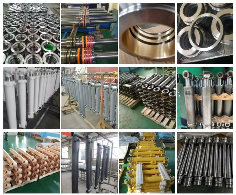
Detailed Photos
Packaging & Shipping
Installation Instructions
Company Profile
- Established in 2571, ZheJiang HONOR INDUSTRIAL CO.,LTD. has import and export rights. Our company fully supplies customers with genuine CHINAMFG spare parts, including fuel systems, cooling systems, lubrication systems, intake and exhaust systems, power systems. Products are widely used in mining, construction engineering, oil field, highway, CHINAMFG and other fields.
Our company also produces various types of rotary CHINAMFG picks, road milling picks, coal mining picks. We have domestic advanced vacuum brazing equipment, top-level robot equipment for robotic arm series joint, and nanotechnology spraying equipment, which can effectively ensure reliable and stable product quality. So as to create a high-end pick product that makes customers more assured and more practical. Products are widely used in highway construction, railway construction, housing construction and other industries.
Our company has a strong technical team, with top technology, rich production experience, sophisticated production equipment, advanced production process, scientific management system and high-quality after-sales service, continuing to grow and develop. "Persistence is belief, integrity is character" is our principle of action, the company will be committed to serving customers at home and a broad with high-quality products and reasonable prices for a long time.
Our Advantages
Price: When ordering in large quantities, the price is guaranteed to be the most competitive on the entire network.
Quality: Genuine parts, fake 1 loses ten.
Delivery time: In order to meet customer needs, our company reserves different models of genuine CHINAMFG spare parts inventory. No matter when and where customers have demand for CHINAMFG engine parts, we can respond quickly, except for some infrequently used parts.
FAQ
Q1: How much is the MOQ?
A: MOQ varies for different products.
Q2: Do you provide sample?
A: Samples can be provided and the cost of ordering samples shall be borne by yourself.
Q3: What is the shipping way?
A: Shipping way is determined according to customer needs, order quantity and product category.
Q4: How long is the delivery time?
A: Picking spot. CHINAMFG products according to supplier, most of the spot or production cycle is about 7 days. The shipping cycle is determined by the shipping method.
Q5: What does the packaging look like?
A: CHINAMFG product packaging is determined by mutual negotiation. The packaging of the picks is subject to our company.
Q6: How to pay?
A: Multiple ways. Mainly T/T.
Q7: What is the after-sales guarantee?
A: Abnormal damage can be claimed. Our company continues to provide technical advice.
Cummins Engine Parts
ZheJiang Honor Company can provide you with pure and high-quality CHINAMFG engine parts of various models. Parts are divided into overhaul parts, common parts, kits, etc. We have a professional and experienced technical service and sales team. According to the engine model you provide, part name or part number, we will be able to respond quickly to your needs.
Cummins common parts
Common parts refer to the parts that may need to be replaced due to damage during routine maintenance or during engine work.
2864571 M11 QSM11 ISM11 Cylinder Head Alternator Starting motor Turbocharger water pump Blet Tensioner Cam Follower Shaft Rocker Sensor for Cylinder Cummins
| Certification: | ISO9001, E-Mark, RoHS, TS16949 |
|---|---|
| Standard Component: | Standard Component |
| Technics: | Push |
| Material: | Iron |
| Type: | Cooler |
| for: | Cummins Engine |
| Customization: |
Available
|
|
|---|
How do hydraulic cylinders handle the challenges of precise positioning and control?
Hydraulic cylinders are designed to handle the challenges of precise positioning and control with a combination of engineering principles and advanced control systems. These challenges often arise in applications where accurate and controlled movements are required, such as in industrial automation, construction, and material handling. Here's a detailed explanation of how hydraulic cylinders overcome these challenges:
1. Fluid Power Control:
- Hydraulic cylinders utilize fluid power control to achieve precise positioning and control. The hydraulic system consists of a hydraulic pump, control valves, and hydraulic fluid. By regulating the flow of hydraulic fluid into and out of the cylinder, operators can control the speed, direction, and force exerted by the cylinder. The fluid power control allows for smooth and accurate movements, enabling precise positioning of the hydraulic cylinder and the attached load.
2. Control Valves:
- Control valves play a crucial role in handling the challenges of precise positioning and control. These valves are responsible for directing the flow of hydraulic fluid within the system. They can be manually operated or electronically controlled. Control valves allow operators to adjust the flow rate of the hydraulic fluid, controlling the speed of the cylinder's movement. By modulating the flow, operators can achieve fine control over the positioning of the hydraulic cylinder, enabling precise and accurate movements.
3. Proportional Control:
- Hydraulic cylinders can be equipped with proportional control systems, which offer enhanced precision in positioning and control. Proportional control systems utilize electronic feedback and control algorithms to precisely regulate the flow and pressure of the hydraulic fluid. These systems provide accurate and proportional control over the movement of the hydraulic cylinder, allowing for precise positioning at various points along its stroke length. Proportional control enhances the cylinder's ability to handle complex tasks that require precise movements and control.
4. Position Feedback Sensors:
- To achieve precise positioning, hydraulic cylinders often incorporate position feedback sensors. These sensors provide real-time information about the position of the cylinder's piston rod. Common types of position feedback sensors include potentiometers, linear variable differential transformers (LVDTs), and magnetostrictive sensors. By continuously monitoring the position, the feedback sensors enable closed-loop control, allowing for accurate positioning and control of the hydraulic cylinder. The feedback information is used to adjust the flow of hydraulic fluid to achieve the desired position accurately.
5. Servo Control Systems:
- Advanced hydraulic systems employ servo control systems to handle the challenges of precise positioning and control. Servo control systems combine electronic control, position feedback sensors, and proportional control valves to achieve high levels of accuracy and responsiveness. The servo control system continuously compares the desired position with the actual position of the hydraulic cylinder and adjusts the flow of hydraulic fluid to minimize any positional error. This closed-loop control mechanism enables the hydraulic cylinder to maintain precise positioning and control, even under varying loads or external disturbances.
6. Integrated Automation:
- Hydraulic cylinders can be integrated into automated systems to achieve precise positioning and control. In such setups, the hydraulic cylinders are controlled by programmable logic controllers (PLCs) or other automation controllers. These controllers receive input signals from various sensors and use pre-programmed logic to command the hydraulic cylinder's movements. The integration of hydraulic cylinders into automated systems allows for precise and repeatable positioning and control, enabling complex sequences of movements to be executed with high accuracy.
7. Advanced Control Algorithms:
- Advancements in control algorithms have also contributed to the precise positioning and control of hydraulic cylinders. These algorithms, such as PID (Proportional-Integral-Derivative) control, adaptive control, and model-based control, enable sophisticated control strategies to be implemented. These algorithms consider factors such as load variations, system dynamics, and environmental conditions to optimize the control of hydraulic cylinders. By employing advanced control algorithms, hydraulic cylinders can compensate for disturbances and achieve precise positioning and control over a wide range of operating conditions.
In summary, hydraulic cylinders overcome the challenges of precise positioning and control through the use of fluid power control, control valves, proportional control, position feedback sensors, servo control systems, integrated automation, and advanced control algorithms. By combining these elements, hydraulic cylinders can achieve accurate and controlled movements, enabling precise positioning and control in various applications. These capabilities are essential for industries that require high precision and repeatability in their operations, such as industrial automation, robotics, and material handling.
What considerations are important when selecting hydraulic cylinders for mobile equipment?
To select hydraulic cylinders for mobile equipment, several important considerations need to be taken into account. Here are the key factors to consider:
- Load Capacity: Determine the maximum load or force that the hydraulic cylinder will need to support. This includes both the static load and any dynamic or shock loads that may be encountered during operation.
- Stroke Length: Consider the required stroke length, which is the distance the hydraulic cylinder can extend and retract. Ensure that the stroke length is sufficient for the specific application and range of motion needed.
- Operating Pressure: Determine the maximum operating pressure required for the hydraulic system. This will depend on the load and the specific application. Select a hydraulic cylinder with a pressure rating that exceeds the maximum operating pressure to ensure safety and durability.
- Mounting Style: Consider the available space and the mounting requirements of the mobile equipment. Hydraulic cylinders come in various mounting styles, such as flange, trunnion, clevis, and pivot, among others. Choose a mounting style that is compatible with the equipment and provides the necessary support and stability.
- Size and Weight: Take into account the physical dimensions and weight of the hydraulic cylinder. Ensure that it can fit within the available space and that the equipment can support its weight without compromising performance or safety.
- Speed and Precision: Evaluate the required speed and precision of the hydraulic cylinder's movement. Different cylinder designs and configurations can affect the speed and accuracy of motion. Consider factors such as cylinder bore size, rod diameter, and the presence of cushioning or dampening features.
- Environmental Factors: Assess the operating environment of the mobile equipment. Consider factors such as temperature extremes, exposure to moisture, dust, and chemicals. Select hydraulic cylinders with appropriate seals and coatings that can withstand the environmental conditions and prevent corrosion or damage.
- Reliability and Maintenance: Consider the reliability and maintenance requirements of the hydraulic cylinders. Look for reputable manufacturers that provide high-quality products with a proven track record. Evaluate factors such as expected service life, availability of spare parts, and ease of maintenance.
- Cost: Finally, consider the cost of the hydraulic cylinders, including the initial purchase price, installation costs, and long-term maintenance expenses. While it is essential to find a cost-effective solution, prioritize quality and performance to ensure safe and efficient operation.
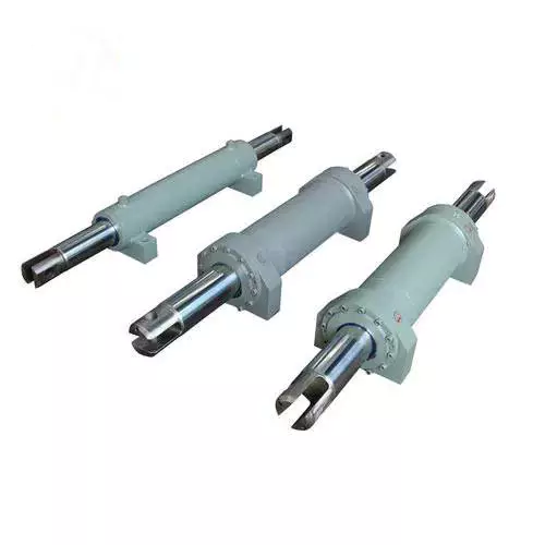
Can you provide real-world examples of machinery that heavily rely on hydraulic cylinders?
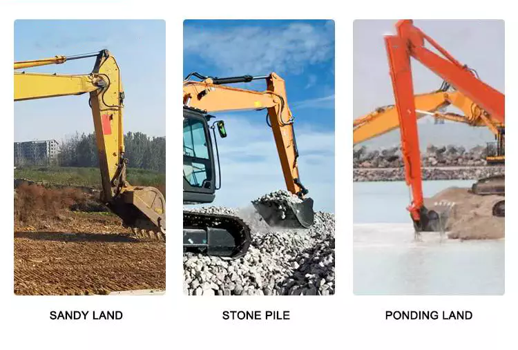
Hydraulic cylinders are widely used in various industries and applications due to their ability to provide powerful and precise linear motion. They play a crucial role in enabling the operation of heavy machinery that requires controlled force and movement. Here are some real-world examples of machinery that heavily rely on hydraulic cylinders:
1. Construction Equipment:
- Hydraulic cylinders are extensively used in construction machinery, such as excavators, bulldozers, loaders, and cranes. These machines rely on hydraulic cylinders to perform tasks like lifting heavy loads, extending and retracting booms, tilting buckets, and controlling the movement of various components. Hydraulic cylinders provide the power and precision required to handle the demanding conditions and heavy loads encountered in construction projects.
2. Agricultural Machinery:
- Many agricultural machines, including tractors, combine harvesters, and sprayers, utilize hydraulic cylinders for critical operations. Hydraulic cylinders are used to control the movement of attachments, such as front loaders, backhoes, and plows. They enable functions like lifting and lowering implements, adjusting cutting heights, and controlling the positioning of harvesting equipment. Hydraulic cylinders enhance efficiency and productivity in agricultural operations.
3. Material Handling Equipment:
- Hydraulic cylinders are integral components of material handling equipment, such as forklifts, pallet jacks, and cranes. These machines rely on hydraulic cylinders to lift and lower loads, tilt platforms or forks, and control the movement of lifting mechanisms. Hydraulic cylinders provide the necessary strength and precision to handle heavy loads and ensure safe and efficient material handling operations.
4. Industrial Machinery:
- Various industrial machinery and equipment heavily rely on hydraulic cylinders for critical functions. Examples include hydraulic presses, injection molding machines, metal-forming machines, and hydraulic-powered robots. Hydraulic cylinders enable precise control of force and movement in these applications, allowing for accurate shaping, pressing, and assembly processes.
5. Mining Equipment:
- Hydraulic cylinders are extensively used in mining machinery and equipment. Underground mining machines, such as continuous miners and longwall shearers, utilize hydraulic cylinders for cutting, shearing, and roof support operations. Surface mining equipment, including hydraulic shovels, draglines, and haul trucks, rely on hydraulic cylinders for tasks like bucket movement, boom extension, and vehicle suspension.
6. Automotive Industry:
- The automotive industry extensively utilizes hydraulic cylinders in various applications. Hydraulic cylinders are employed in vehicle suspension systems, power steering systems, convertible tops, and hydraulic brake systems. They enable smooth and controlled movement, precise steering, and efficient braking in automobiles.
7. Aerospace and Aviation:
- Hydraulic cylinders are utilized in aerospace and aviation applications, such as aircraft landing gear systems, wing flaps, and cargo handling equipment. Hydraulic cylinders provide the necessary force and control for extending and retracting landing gear, adjusting wing flaps, and operating cargo doors, ensuring safe and reliable aircraft operations.
8. Marine and Offshore Industry:
- Hydraulic cylinders are essential components in marine and offshore equipment, including ship cranes, winches, and hydraulic-powered anchor systems. They enable lifting, lowering, and positioning of heavy loads, as well as the control of various marine equipment.
These are just a few examples of machinery and industries that heavily rely on hydraulic cylinders. The versatility, power, and precise control offered by hydraulic cylinders make them indispensable in a wide range of applications, where controlled linear motion and force are essential.


editor by CX 2023-10-29
China factory Original Wheel Loader Spare Parts Hydraulic Cylinder Xt870.3.1.2.11 for Wheel Loader/Grader Motor vacuum pump ac
Product Description
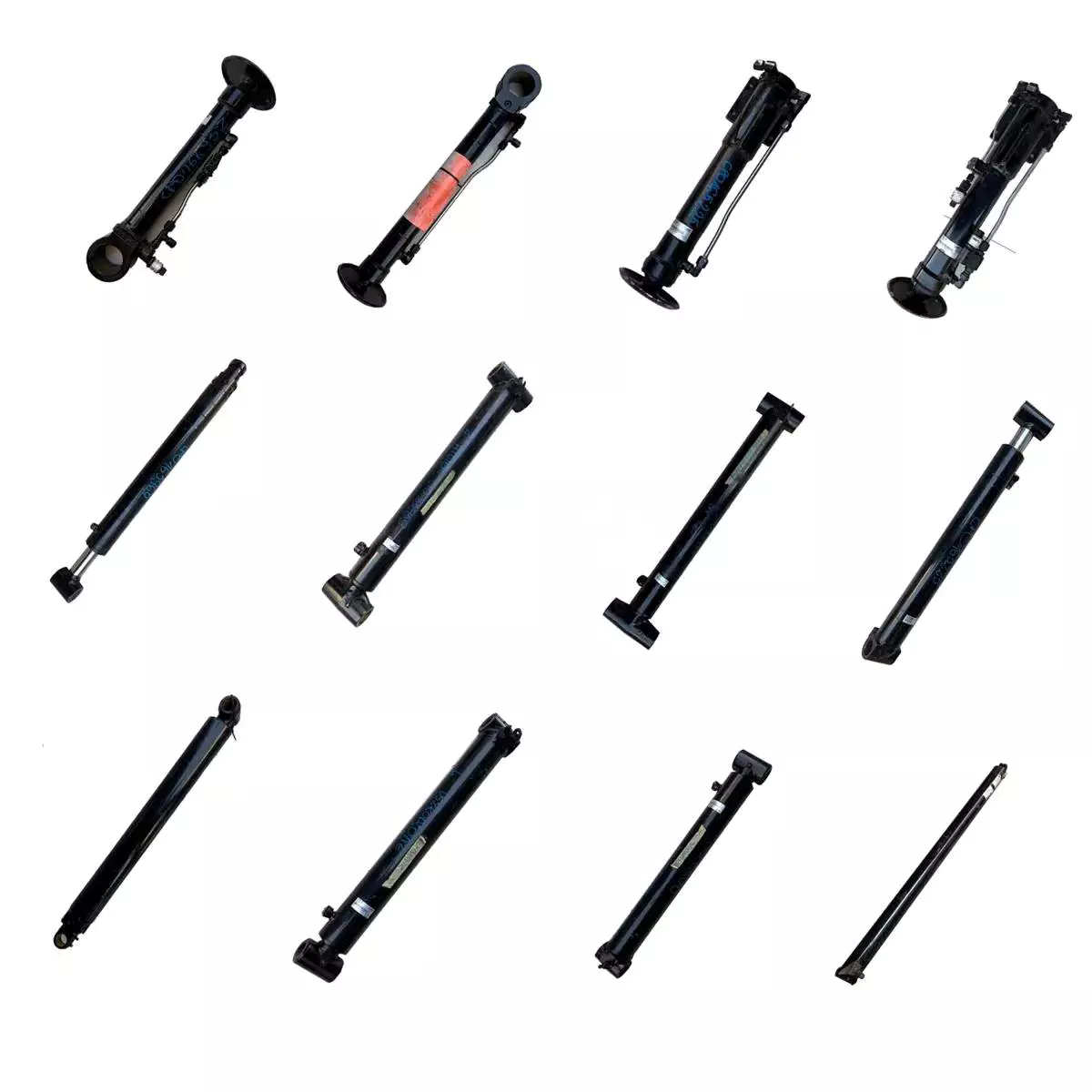
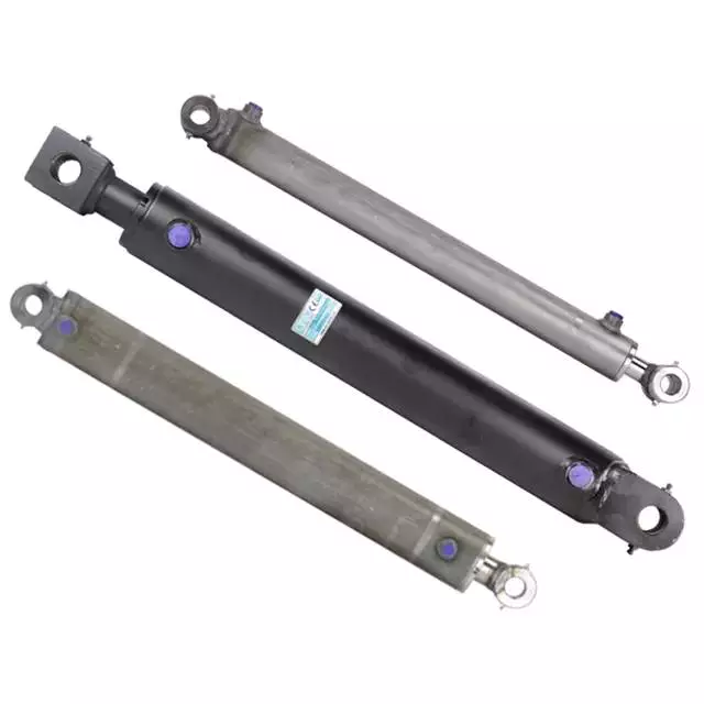
Original Wheel Loader Spare Parts Hydraulic Cylinder XT870.3.1.2.11
|
Part Name |
Hydraulic Cylinder |
Brand Name |
|
|
Part Number |
XT870.3.1.2.11 |
Application |
Wheel Loader |
|
Mini Order |
One Set/ Piece |
Packing |
Carton,Wooden Box, Pallet |
|
Supply Ability |
10000 Pieces |
OEM |
Available |
|
Quality Standard |
100% Tested |
Quality Certification |
ISO,CCC,GSO,CE,SGS,TUV |
|
Condition |
New |
Payment Terms |
L/C, T/T, Western Union,Paypal |
|
Origin |
China |
Loading Port |
Any Port In China |
Company Information / About Us
ZheJiang CHINAMFG VEHICLE TRADING CO., LTD (HOKA VEHICLE hereafter in short) has been engaged in the heavy duty truck industry for more than 15 years. With the professional team and first class design and production experience and market capacity, CHINAMFG VEHICLE has exported and delivered more than 5,000 units heavy duty trucks to countries across Africa Middle East, Southeast Asia and South America.
HOKA VEHILCE maintains dealership and distribution authorization from manufacturer including SINOTRUK, SHACMAN, FOTON, CIMC, SHENGRUN, HELI, etc. Our main products range from Dump truck, Tractor Truck, Concrete Mixer, Truck Van, Truck Lorry Truck, Off-road Dump, Truck Tanker, Truck Mounted Cranes, trailer tanker, trailers and all other kinds of modified trucks.
HOKA VEHILCE, we transport your cargos, we deliver the world, we carry your dreams!
Why Choose Us
Worldwide Sales, Marketing and Service Network
During the past 15 years, we have exported over 5,000 units of different kinds of heavy duty trucks to over 50 countries in Africa, Middle East, Southeast Asia, and South America. Our overseas authorized truck dealers and service dealers are all around the world.
Wide Ranges of Various Modified Trucks with Different Applications
Our main products range from Dump Truck, Tractor Truck, Concrete Mixer Truck, Van Truck, Lorry Truck, Off-road Dump Truck, Tanker Truck, Truck Mounted Cranes, trailer, tanker trailers and all other kinds of modified trucks. We can design, produce and supply our customers with any special vehicle.
Flexible Payment Terms for Different Trucks and Business
Besides traditional payment terms such as TT, LC, we still offer our stable and long-term partners with various financial support and credit payment terms at different periods.
Excellent and Outstanding After Sales Service
Our professional technicians and mechanics and parts staff always concentrate all our products and our customers. Top Starting Point, High Quality and Worry-free Service is our promise to all our customers.
High Efficiency is One of Our Goal and Promise to Our Customers
We will be always with our customers whenever and wherever we are. All problems and questions shall be solved by our end at the first time. Customer priority outstands without any doubt.
Latest Truck Development and Trends Shall Be Delivered Regularly
We have abundant technical team, familiar with local and major exporter product standards. Our customers will be regularly updated with the latest truck development and trends in China and other countries.
Who we are?
The most professional truck and spare parts distributor in China;
The leading truck and spare parts exporter in China;
The most comprehensive truck and spare parts solution provider in China;
The most worry-free and most satisfactory and reputable supplier for you in China.
We will never let you down if you choose us.
Contact us:
Sales Manager: Lock Wu
| Type: | Wheel Loader |
|---|---|
| Muffler Type: | Wheel Loader |
| Deck: | Wheel Loader |
| OEM: | Available |
| Stock: | Available |
| Min. Order Quantity: | 1 |
| Samples: |
US$ 441/Piece
1 Piece(Min.Order) | |
|---|
| Customization: |
Available
|
|
|---|
What advancements in hydraulic cylinder technology have improved energy efficiency?
Advancements in hydraulic cylinder technology have led to significant improvements in energy efficiency, allowing hydraulic systems to operate more efficiently and reduce energy consumption. These advancements aim to minimize energy losses, optimize system performance, and enhance overall efficiency. Here's a detailed explanation of some key advancements in hydraulic cylinder technology that have improved energy efficiency:
1. Efficient Hydraulic Circuit Design:
- The design of hydraulic circuits has evolved to improve energy efficiency. Advancements in circuit design techniques, such as load-sensing, pressure-compensated systems, or variable displacement pumps, help match the hydraulic power output to the actual load requirements. These designs reduce unnecessary energy consumption by adjusting the flow and pressure levels according to the system demands, rather than operating at a fixed high pressure.
2. High-Efficiency Hydraulic Fluids:
- The development of high-efficiency hydraulic fluids, such as low-viscosity or synthetic fluids, has contributed to improved energy efficiency. These fluids offer lower internal friction and reduced resistance to flow, resulting in decreased energy losses within the system. Additionally, advanced fluid additives and formulations enhance lubrication properties, reducing friction and optimizing the overall efficiency of hydraulic cylinders.
3. Advanced Sealing Technologies:
- Seal technology has advanced significantly, leading to improved energy efficiency in hydraulic cylinders. High-performance seals, such as low-friction or low-leakage seals, minimize internal leakage and friction losses. Reduced internal leakage helps maintain system pressure more effectively, resulting in less energy waste. Additionally, innovative sealing materials and designs enhance durability and extend seal life, reducing the need for frequent maintenance and replacement.
4. Electro-Hydraulic Control Systems:
- The integration of advanced electro-hydraulic control systems has greatly contributed to energy efficiency improvements. By combining electronic control with hydraulic power, these systems enable precise control over cylinder operation, optimizing energy usage. Proportional or servo valves, along with position or force feedback sensors, allow for accurate and responsive control, ensuring that hydraulic cylinders operate at the required level of performance while minimizing energy waste.
5. Energy Recovery Systems:
- Energy recovery systems, such as hydraulic accumulators, have been increasingly utilized to improve energy efficiency in hydraulic cylinder applications. Accumulators store excess energy during low-demand periods and release it when there is a peak demand, reducing the need for the hydraulic pump to provide the full power continuously. By utilizing stored energy, these systems can significantly reduce energy consumption and improve overall system efficiency.
6. Smart Monitoring and Control:
- Advancements in smart monitoring and control technologies have enabled real-time monitoring of hydraulic systems, allowing for optimized energy usage. Integrated sensors, data analytics, and control algorithms provide insights into system performance and energy consumption, enabling operators to make informed decisions and adjustments. By identifying inefficiencies or suboptimal operating conditions, energy consumption can be minimized, leading to improved energy efficiency.
7. System Integration and Optimization:
- The integration and optimization of hydraulic systems as a whole have played a significant role in improving energy efficiency. By considering the entire system layout, component sizing, and interaction between different elements, engineers can design hydraulic systems that operate in the most energy-efficient manner. Proper sizing of components, minimizing pressure drops, and reducing unnecessary piping or valve restrictions all contribute to improved energy efficiency of hydraulic cylinders.
8. Research and Development:
- Ongoing research and development efforts in the field of hydraulic cylinder technology continue to drive energy efficiency advancements. Innovations in materials, component design, system modeling, and simulation techniques help identify areas for improvement and optimize energy usage. Additionally, collaboration between industry stakeholders, research institutions, and regulatory bodies fosters the development of energy-efficient hydraulic cylinder technologies.
In summary, advancements in hydraulic cylinder technology have resulted in notable improvements in energy efficiency. Efficient hydraulic circuit designs, high-efficiency hydraulic fluids, advanced sealing technologies, electro-hydraulic control systems, energy recovery systems, smart monitoring and control, system integration and optimization, as well as ongoing research and development efforts, all contribute to reducing energy consumption and enhancing the overall energy efficiency of hydraulic cylinders. These advancements not only benefit the environment but also offer cost savings and improved performance in various hydraulic applications.
Ensuring Stable Performance of Hydraulic Cylinders Under Fluctuating Loads
Hydraulic cylinders are designed to provide stable performance even under fluctuating loads. They achieve this through various mechanisms and features that allow for efficient load control and compensation. Let's explore how hydraulic cylinders ensure stable performance under fluctuating loads:
- Piston Design: The piston inside the hydraulic cylinder plays a crucial role in load control. It is typically equipped with seals and rings that prevent leakage of hydraulic fluid and ensure effective transfer of force. The piston design may incorporate features such as stepped or tandem pistons, which provide enhanced load-bearing capabilities and improved stability by distributing the load across multiple surfaces.
- Cylinder Cushioning: Hydraulic cylinders often incorporate cushioning mechanisms to minimize the impact and shock caused by fluctuating loads. Cushioning can be achieved through various methods, such as adjustable cushion screws, hydraulic cushioning valves, or elastomeric cushioning rings. These mechanisms slow down the piston's movement near the end of the stroke, reducing the impact and preventing sudden stops that could lead to instability.
- Pressure Compensation: Fluctuating loads can result in pressure variations within the hydraulic system. To ensure stable performance, hydraulic cylinders are equipped with pressure compensation mechanisms. These mechanisms maintain a consistent pressure level in the system, regardless of load changes. Pressure compensation can be achieved through the use of pressure relief valves, compensating pistons, or pressure-compensated flow control valves.
- Flow Control: Hydraulic cylinders often incorporate flow control valves to regulate the speed of the cylinder's movement. By controlling the flow rate of hydraulic fluid, the cylinder's motion can be adjusted to match the changing load conditions. Flow control valves allow for smooth and controlled movement, preventing abrupt changes that could lead to instability.
- Feedback Systems: To ensure stable performance under fluctuating loads, hydraulic cylinders can be integrated with feedback systems. These systems provide real-time information on the cylinder's position, velocity, and force. By continuously monitoring these parameters, the hydraulic system can make immediate adjustments to maintain stability and compensate for load fluctuations. Feedback systems can include position sensors, pressure sensors, or load sensors, depending on the specific application.
- Proper Sizing and Selection: Ensuring stable performance under fluctuating loads starts with proper sizing and selection of hydraulic cylinders. It is crucial to choose cylinders with appropriate bore size, rod diameter, and stroke length to match the anticipated load conditions. Oversized or undersized cylinders can lead to instability and reduced performance. Proper sizing also involves considering factors such as the required force, speed, and duty cycle of the application.
In summary, hydraulic cylinders ensure stable performance under fluctuating loads through features such as piston design, cushioning mechanisms, pressure compensation, flow control, feedback systems, and proper sizing and selection. These mechanisms and considerations allow hydraulic cylinders to provide consistent and controlled movement, even in dynamic load conditions, resulting in reliable and stable performance.
How do hydraulic cylinders generate force and motion using hydraulic fluid?
Hydraulic cylinders generate force and motion by utilizing the principles of fluid mechanics, specifically Pascal's law, in conjunction with the properties of hydraulic fluid. The process involves the conversion of hydraulic energy into mechanical force and linear motion. Here's a detailed explanation of how hydraulic cylinders achieve this:
1. Pascal's Law:
- Hydraulic cylinders operate based on Pascal's law, which states that when pressure is applied to a fluid in a confined space, it is transmitted equally in all directions. In the context of hydraulic cylinders, this means that when hydraulic fluid is pressurized, the force is evenly distributed throughout the fluid and transmitted to all surfaces in contact with the fluid.
2. Hydraulic Fluid and Pressure:
- Hydraulic systems use a specialized fluid, typically hydraulic oil, as the working medium. This fluid is stored in a reservoir and circulated through the system by a hydraulic pump. The pump pressurizes the fluid, creating hydraulic pressure that can be controlled and directed to various components, including hydraulic cylinders.
3. Cylinder Design and Components:
- Hydraulic cylinders consist of several key components, including a cylindrical barrel, a piston, a piston rod, and various seals. The barrel is a hollow tube that houses the piston and allows for fluid flow. The piston divides the cylinder into two chambers: the rod side and the cap side. The piston rod extends from the piston and provides a connection point for external loads. Seals are used to prevent fluid leakage and maintain hydraulic pressure within the cylinder.
4. Fluid Input and Motion:
- To generate force and motion, hydraulic fluid is directed into one side of the cylinder, creating pressure on the corresponding surface of the piston. This pressure is transmitted through the fluid to the other side of the piston.
5. Force Generation:
- The force generated by a hydraulic cylinder is a result of the pressure applied to a specific surface area of the piston. The force exerted by the hydraulic cylinder can be calculated using the formula: Force = Pressure × Area. The area is determined by the diameter of the piston or the piston rod, depending on which side of the cylinder the fluid is acting upon.
6. Linear Motion:
- As the pressurized hydraulic fluid acts on the piston, it generates a force that moves the piston in a linear direction within the cylinder. This linear motion is transferred to the piston rod, which extends or retracts accordingly. The piston rod can be connected to external components or machinery, allowing the generated force to perform various tasks, such as lifting, pushing, pulling, or controlling mechanisms.
7. Control and Regulation:
- The force and motion generated by hydraulic cylinders can be controlled and regulated by adjusting the flow of hydraulic fluid into the cylinder. By regulating the flow rate, pressure, and direction of the fluid, the speed, force, and direction of the cylinder's movement can be precisely controlled. This control allows for accurate positioning, smooth operation, and synchronization of multiple cylinders in complex machinery.
8. Return and Recirculation of Fluid:
- After the hydraulic cylinder completes its stroke, the hydraulic fluid on the opposite side of the piston needs to be returned to the reservoir. This is typically achieved through hydraulic valves that control the flow direction, allowing the fluid to return and be recirculated in the system for further use.
In summary, hydraulic cylinders generate force and motion by utilizing the principles of Pascal's law. Pressurized hydraulic fluid acts on the piston, creating force that moves the piston in a linear direction. This linear motion is transferred to the piston rod, allowing the generated force to perform various tasks. By controlling the flow of hydraulic fluid, the force and motion of hydraulic cylinders can be precisely regulated, contributing to their versatility and wide range of applications in machinery.
editor by CX 2023-10-15
China OEM Hot Sale AC Gear Motor Right Angle Speed Reducer for Wall Breaker manufacturer
Product Description
TaiBang Motor Industry Group Co., Ltd.
The main products is induction motor, reversible motor, DC brush gear motor, DC brushless gear motor, CH/CV big gear motors, Planetary gear motor ,Worm gear motor etc, which used widely in various fields of manufacturing pipelining, transportation, food, medicine, printing, fabric, packing, office, apparatus, entertainment etc, and is the preferred and matched product for automatic machine.
Motor Model Instruction
5RK40GN-CM
| 5 | R | K | 40 | R | GN | C | M |
| Frame Size | Type | Motor series | Power | Speed Control Motor |
Shaft Type | Voltage | Accessory |
| 2:60mm
3:70mm 4:80mm 5:90mm 6:104mm |
I:Induction
R:Reversible T:Torque |
K series | 6W
15W 25W 40W 60W 90W 120W 140W 180W 200W |
A:Round Shaft
GN:Bevel Gear Shaft GU:Bevel Gear Shaft |
A:Single Phase 110V
C:Single Phase 220V S:3-Phase 220V S3:3-Phase 380V S4:3-Phase 440V |
T/P:Thermally Protected
F:Fan M:Electro-magnetic |
Gear Head Model Instruction
5GN-100K
| 5 | GN | 100 | K | |
| Frame Size | Shaft Type | Gear Reduction Ratio | Bearing Type | Other information |
| 2:60mm
3:70mm 4:80mm 5:90mm 6:104mm |
GN:Bevel Gear Shaft (60#,70#,80#,90# reduction gear head) GU:Bevel Gear Shaft GM:Intermediate Gear Head GS:Gearhead with ears |
1:100 | K:Standard Rolling Bearing
RT:Right Angle With Axile RC:Right Angle With Hollow Shaft |
Such as shaft diameter,shaft length,etc. |
Specification of motor 40W 90mm Fixed speed AC gear motor
| Type | Gear Tooth Output Shaft | Power (W) |
Frequency (Hz) |
Voltage (V) |
Current (A) |
Start Torque (g.cm) |
Rated | Gearbox Type | ||
| Torque (g.cm) |
Speed (rpm) |
Bearing Gearbox | Middle Gearbox | |||||||
| Reversible Motor | 5RK40GN-C | 40 | 50 | 220 | 0.45 | 3000 | 3000 | 1300 | 5GN/GU-K | 5GN10X |
| 40 | 60 | 220 | 0.41 | 2500 | 2515 | 1550 | 5GN/GU-K | 5GN10X | ||
Gear Head Torque Table(Kg.cm) (kg.cm×9.8÷100)=N.m
| Output Speed :RPM | 500 | 300 | 200 | 150 | 120 | 100 | 75 | 60 | 50 | 30 | 20 | 15 | 10 | 7.5 | 6 | 5 | 3 | ||
| Speed Ratio | 50Hz | 3 | 5 | 7.5 | 10 | 12.5 | 15 | 20 | 25 | 30 | 50 | 75 | 100 | 150 | 200 | 250 | 300 | 500 | |
| 60Hz | 3.6 | 6 | 9 | 15 | 18 | 30 | 36 | 60 | 90 | 120 | 180 | 300 | 360 | 600 | |||||
| Allowed Torque |
40W | kg.cm | 6.7 | 11 | 16 | 21.3 | 28 | 33 | 42 | 54 | 65 | 108 | 150 | 150 | 150 | 150 | 150 | 150 | 150 |
| 60W | kg.cm | 10 | 16 | 24 | 32 | 40 | 48 | 64 | 77 | 93 | 150 | 150 | 150 | 150 | 150 | 150 | 150 | 150 | |
| 90W | kg.cm | 14 | 23 | 35 | 46 | 58 | 69 | 92 | 110 | 133 | 200 | 200 | 200 | 200 | 200 | 200 | 200 | 200 | |
| 120W | kg.cm | 19 | 30.7 | 46 | 61 | 77 | 92 | 123 | 147 | 177 | 200 | 200 | 200 | 200 | 200 | 200 | 200 | 200 | |
| Note: Speed figures are based on synchronous speed, The actual output speed, under rated torque conditions, is about 10-20% less than synchronous speed, a grey background indicates output shaft of geared motor rotates in the same direction as output shaft of motor. A white background indicates rotates rotation in the opposite direction. | |||||||||||||||||||
Drawing:5RK40GN-C/5GN3~20K(Short gearbox shell 43mm)
Drawing:5RK40GN-C/5GN25~180K(Short gearbox shell 61mm)
Above drawing is for standard screw hole.If need through hole, terminal box, or electronic magnet brake, need to tell the seller.
Connection Diagram:
| Application: | Industrial |
|---|---|
| Speed: | Constant Speed |
| Number of Stator: | Single-Phase |
| Function: | Driving, Control |
| Casing Protection: | Closed Type |
| Number of Poles: | 4 |
| Samples: |
US$ 50/Piece
1 Piece(Min.Order) | |
|---|
| Customization: |
Available
| Customized Request |
|---|
Can gear reducers be customized for specific industrial needs and requirements?
Yes, gear reducers can be customized to meet specific industrial needs and requirements. Manufacturers offer customization options to ensure that gear reducers are tailored to the unique demands of various applications:
1. Gear Ratio Selection: Gear reducers can be designed with specific gear ratios to achieve the desired speed reduction or increase, catering to the specific requirements of the machinery or equipment.
2. Shaft Configurations: Gear reducers can be configured with different shaft sizes, lengths, and orientations to fit seamlessly into existing systems or accommodate specific mounting arrangements.
3. Torque Capacity: Customized gear reducers can be designed to handle higher or lower torque loads based on the application's operational requirements.
4. Environmental Considerations: Gear reducers can be customized with special coatings, materials, or seals to withstand harsh environments, extreme temperatures, or corrosive conditions.
5. Noise and Vibration Reduction: Custom designs can incorporate features to reduce noise and dampen vibrations, enhancing the overall operation and user experience.
6. Mounting and Connection Options: Manufacturers can adapt gear reducer designs to include specific mounting interfaces or connection methods that align with the equipment's design.
7. Lubrication and Maintenance: Customized gear reducers can include features for easy maintenance, such as accessible lubrication points or monitoring systems.
8. Integration with Controls: Gear reducers can be customized to integrate seamlessly with control systems, sensors, or automation processes, enhancing system efficiency and performance.
By collaborating with manufacturers and providing detailed specifications, industries can obtain tailor-made gear reducers that address their specific operational needs and contribute to the success of their applications.

What factors should be considered when selecting the right gear reducer?
Choosing the appropriate gear reducer involves considering several crucial factors to ensure optimal performance and efficiency for your specific application:
- 1. Torque and Power Requirements: Determine the amount of torque and power your machinery needs for its operation.
- 2. Speed Ratio: Calculate the required speed reduction or increase to match the input and output speeds.
- 3. Gear Type: Select the appropriate gear type (helical, bevel, worm, planetary, etc.) based on your application's torque, precision, and efficiency requirements.
- 4. Mounting Options: Consider the available space and the mounting configuration that suits your machinery.
- 5. Environmental Conditions: Evaluate factors such as temperature, humidity, dust, and corrosive elements that may impact the gear reducer's performance.
- 6. Efficiency: Assess the gear reducer's efficiency to minimize power losses and improve overall system performance.
- 7. Backlash: Consider the acceptable level of backlash or play between gear teeth, which can affect precision.
- 8. Maintenance Requirements: Determine the maintenance intervals and procedures necessary for reliable operation.
- 9. Noise and Vibration: Evaluate noise and vibration levels to ensure they meet your machinery's requirements.
- 10. Cost: Compare the initial cost and long-term value of different gear reducer options.
By carefully assessing these factors and consulting with gear reducer manufacturers, engineers and industry professionals can make informed decisions to select the right gear reducer for their specific application, optimizing performance, longevity, and cost-effectiveness.

Are there variations in gear reducer designs for specific tasks and applications?
Yes, gear reducer designs vary widely to suit specific tasks and applications across various industries. Manufacturers offer a range of gear reducer types and configurations to accommodate different requirements, including:
- Helical Gear Reducers: These are versatile and provide smooth and efficient torque transmission. They are commonly used in applications requiring high precision and moderate speed reduction, such as conveyors, mixers, and agitators.
- Bevel Gear Reducers: These are ideal for transmitting power between intersecting shafts. They are often used in heavy machinery, printing presses, and automotive applications.
- Worm Gear Reducers: These provide compact solutions and are suitable for applications with higher speed reduction requirements, such as conveyor systems, winches, and elevators.
- Planetary Gear Reducers: These offer high torque density and are used in applications demanding precise control, such as robotics, aerospace, and heavy-duty machinery.
- Parallel Shaft Gear Reducers: Commonly used in industrial machinery, these reducers are designed for high torque and reliability.
- Right-Angle Gear Reducers: These are used when space limitations require a change in shaft direction, commonly found in packaging equipment and conveyors.
Each type of gear reducer has unique features and benefits that make it suitable for specific tasks. Manufacturers often provide customization options to tailor gear reducers to the precise requirements of an application, including gear ratios, mounting options, and input/output configurations.
Therefore, the variation in gear reducer designs allows industries to select the most appropriate type based on factors such as torque, speed, space constraints, precision, and environmental conditions.
editor by CX 2023-10-07
China factory AC Three Phase 240V 400V Parallet Shaft Helical Reducer Gear Motor manufacturer
Product Description
AC Three 3 Phase 240V 400V Parallet shaft Helical Reducer Gear Motor
Features:
1. Compact structure and simple assembly;
2. Wide speed ranges and high torque;
3. Low noise, good sealing performance, high efficiency;
4. Stable and safe, long lifetime, universal;
5. Multi-structure, various assembling methods
Product photo:
Specification:
| ANG Helical Gear Motor | |
| Model | R17 ~ 187, F37-177, K37-187, S37-97 |
| Input power | 0.06kw ~ 250kw |
| Input speed | 750rpm ~ 3000rpm |
| Reduction ratio | 1/1.3 ~ 1/27000 |
| Input motor | AC (1 phase or 3 phase) / DC / BLDC motor |
| Install type | Foot / CHINAMFG shaft / Hollow shaft / Output flange… |
| Efficiency | 94% ~ 98 % for R F K series |
| Material of housing | die-cast aluminum / Cast iron / Stainless steel |
| Precision of gear | Accurate grinding, class 6 |
| Heat treatment | Carburizing and quenching |
| Accessories | Brake / Flange / Motor adapter / Torque arm … |
FAQ
Q: Can you make the gear motor with customization?
A: Yes, we can customize per your request, like power, voltage, speed, shaft size, flange, terminal box, IP grade, etc.
Q: Do you provide samples?
A: Yes. Sample is available for testing.
Q: What is your MOQ?
A: It is 1pcs for the beginning of our business.
Q: What's your lead time?
A: Standard product need 5-30days, a bit longer for customized products.
Q: Do you provide technology support?
A: Yes. Our company have design and development team, we can provide technology support if you
need.
Q: How to ship to us?
A: It is available by air, or by sea, or by train.
Q: How to pay the money?
A: T/T and L/C is preferred, with different currency, including USD, EUR, RMB, etc.
Q: How can I know the product is suitable for me?
A: >1ST confirm drawing and specification >2nd test sample >3rd start mass production.
Q: Can I come to your company to visit?
A: Yes, you are welcome to visit us at any time.
Q: How shall we contact you?
A: You can send inquiry directly, and we will respond within 24 hours.
|
Shipping Cost:
Estimated freight per unit. |
To be negotiated |
|---|
| Application: | Industrial |
|---|---|
| Speed: | Constant Speed |
| Number of Stator: | Single or Three Phase |
| Samples: |
US$ 300/Piece
1 Piece(Min.Order) | Order Sample |
|---|
| Customization: |
Available
| Customized Request |
|---|
How do gear reducers enhance the efficiency of conveyor systems and robotics?
Gear reducers play a significant role in improving the efficiency of both conveyor systems and robotics by optimizing speed, torque, and control. Here's how they contribute:
Conveyor Systems:
In conveyor systems, gear reducers enhance efficiency in the following ways:
- Speed Control: Gear reducers allow precise control over the rotational speed of conveyor belts, ensuring that materials are transported at the desired speed for efficient production processes.
- Torque Adjustment: By adjusting gear ratios, gear reducers provide the necessary torque to handle varying loads and prevent overloading, minimizing energy wastage.
- Reverse Operation: Gear reducers enable smooth bidirectional movement of conveyor belts, facilitating tasks such as loading, unloading, and distribution without the need for additional components.
- Synchronization: Gear reducers ensure synchronized movement of multiple conveyor belts in complex systems, optimizing material flow and minimizing jams or bottlenecks.
Robotics:
In robotics, gear reducers enhance efficiency through the following means:
- Precision Movement: Gear reducers provide precise control over the movement of robot joints and arms, enabling accurate positioning and manipulation of objects.
- Reduced Inertia: Gear reducers help reduce the inertia experienced by robotic components, allowing for quicker and more responsive movements while conserving energy.
- Compact Design: Gear reducers offer a compact and lightweight solution for achieving various motion profiles in robotic systems, allowing for efficient use of space and resources.
- Torque Amplification: By amplifying torque from the motor, gear reducers enable robots to handle heavier loads and perform tasks that require greater force, enhancing their overall capabilities.
By providing precise speed control, torque adjustment, and reliable motion transmission, gear reducers optimize the performance of conveyor systems and robotics, leading to improved efficiency, reduced energy consumption, and enhanced operational capabilities.

How do gear reducers handle shock loads and sudden changes in torque?
Gear reducers are designed to handle shock loads and sudden changes in torque through several mechanisms that enhance their durability and reliability in challenging operating conditions.
1. Robust Construction: Gear reducers are constructed using high-strength materials and precision manufacturing techniques. This ensures that the gears, bearings, and other components can withstand sudden impacts and high torque fluctuations without deformation or failure.
2. Shock-Absorbing Features: Some gear reducer designs incorporate shock-absorbing features, such as flexible couplings, elastomeric elements, or torsionally flexible gear designs. These features help dampen and dissipate the energy from sudden shocks or torque spikes, reducing the impact on the entire system.
3. Torque Limiters: In applications where shock loads are common, torque limiters may be integrated into the gear reducer. These devices automatically disengage or slip when a certain torque threshold is exceeded, preventing damage to the gears and other components.
4. Overload Protection: Gear reducers can be equipped with overload protection mechanisms, such as shear pins or torque sensors. These mechanisms detect excessive torque and disengage the drive temporarily, allowing the system to absorb the shock or adjust to the sudden torque change.
5. Proper Lubrication: Adequate lubrication is essential for managing shock loads and sudden torque changes. High-quality lubricants reduce friction and wear, helping the gear reducer withstand dynamic forces and maintain smooth operation.
6. Dynamic Load Distribution: Gear reducers distribute dynamic loads across multiple gear teeth, which helps prevent localized stress concentrations. This feature minimizes the risk of tooth breakage and gear damage when subjected to sudden changes in torque.
By incorporating these design features and mechanisms, gear reducers can effectively handle shock loads and sudden changes in torque, ensuring the longevity and reliability of various industrial and mechanical systems.

What industries and machinery commonly utilize gear reducers?
Gear reducers are widely used across various industries and types of machinery for torque reduction and speed control. Some common industries and applications include:
- 1. Manufacturing: Gear reducers are used in manufacturing equipment such as conveyors, mixers, and packaging machines to control speed and transmit power efficiently.
- 2. Automotive: They are utilized in vehicles for applications like power transmission in transmissions and differentials.
- 3. Aerospace: Gear reducers are used in aircraft systems, including landing gear mechanisms and engine accessories.
- 4. Robotics and Automation: They play a crucial role in robotic arms, CNC machines, and automated production lines.
- 5. Mining and Construction: Gear reducers are used in heavy machinery like excavators, bulldozers, and crushers for power transmission and torque multiplication.
- 6. Energy and Power Generation: Wind turbines, hydroelectric generators, and other power generation equipment use gear reducers to convert rotational speed and transmit power.
- 7. Marine and Shipbuilding: They are used in ship propulsion systems, steering mechanisms, and anchor handling equipment.
- 8. Material Handling: Gear reducers are essential in conveyor systems, elevators, and hoists for controlled movement of materials.
- 9. Food and Beverage: They find applications in food processing equipment like mixers, grinders, and packaging machines.
- 10. Paper and Pulp: Gear reducers are used in machinery for pulp processing, paper production, and printing.
These examples represent just a fraction of the industries and machinery that benefit from the use of gear reducers to optimize power transmission and achieve the desired motion characteristics.
editor by CX 2023-10-07
China factory RV 0.06kw~15kw Worm Gearbox with Electric AC Motor with Good quality
Product Description
RV 0.06KW~15KW Worm Gearbox with Electric AC Motor
Product Description
NMRV 571-150 worm gear box with flange and electric motor
NMRV+NMRV Double Stage Arrangement Reduction Gear Box
RV Series Worm Gearbox
worm speed reducer
nmrv worm gear motor
Detailed Photos
RV Series
Including RV / NMRV / NRV.
Main Characteristic of RV Series Worm Gearbox
RV series worm gear reducer is a new-generation product developed by CHINAMFG on the basis of perfecting WJ series products with a compromise of advanced technology both at home and abroad.
1. High-quality aluminum alloy, light in weight and non-rusting.
2. Large in output torque.
3. Smooth running and low noise,durable in dreadful conditions.
4. High radiation efficiency.
5. Good-looking appearance, durable in service life and small volume.
6. Suitable for omnibearing installation.
Main Materials of RV Series Worm Gearbox
1. Housing: die-cast aluminum alloy(frame size: 571 to 090), cast iron(frame size: 110 to 150).
2. Worm: 20Crm, carbonization quencher heat treatment makes the surface hardness of worm gears up to 56-62 HRX, retain carbonization layer's thickness between 0.3 and 0.5mm after precise grinding.
3. Worm Wheel: wearable stannum bronze alloy.
| SPEED RATIO | 7.5~100 |
| OUTPUT TORQUE | <1050NM |
| IN POWER | 0.09-11KW |
| MOUNTING TYPE | FOOT-MOUNTED FLANGE-MOUNTED |
Product Parameters
| When working, great load capacity, stable running, low noise with high efficiency. | |||||||
| Gear Box's Usage Field | |||||||
| 1 | Metallurgy | 11 | Agitator | ||||
| 2 | Mine | 12 | Rotary weeder | ||||
| 3 | Machine | 13 | Metallurgy | ||||
| 4 | Energy | 14 | Compressor | ||||
| 5 | Transmission | 15 | Petroleum industry | ||||
| 6 | Water Conserbancy | 16 | Air Compressor | ||||
| 7 | Tomacco | 17 | Crusher | ||||
| 8 | Medical | 18 | Materials | ||||
| 9 | Packing | 19 | Electronics | ||||
| 10 | Chemical industry | 20 | Textile indutry | ||||
| ... | ... | ||||||
| Power | 0.06kw | 0.09kw | 0.12kw | 0.18kw | 0.25kw | 0.37kw | 0.55kw |
| 0.75kw | 1.1kw | 1.5kw | 2.2kw | 3kw | 4kw | 5.5kw | |
| 7.5kw | 11kw | 15kw | |||||
| Torque | 2.6N.m-3000N.m | ||||||
| Ratio | 7.5-100, the double gearbox is more | ||||||
| Color | Blue, Silver or as customers' need | ||||||
| Material | Iron or Aluminium | ||||||
| Packing | Carton with Plywood Case or as clients' requirement | ||||||
| Type | RV571 | RV030 | RV040 | RV050 | RV063 | RV075 | RV090 |
| Weight | 0.7kg | 1.3kg | 2.3kg | 3.5kg | 6.2kg | 9kg | 13kg |
| Type | RV110 | RV130 | RV150 | ||||
| Weight | 35kg | 60kg | 84kg | ||||
Certifications
Packaging & Shipping
Company Profile
Our Advantages
FAQ
| Application: | Motor, Machinery |
|---|---|
| Hardness: | Hardened Tooth Surface |
| Installation: | Horizontal Type |
| Layout: | Worm |
| Gear Shape: | Worm |
| Step: | Single-Step |
| Customization: |
Available
| Customized Request |
|---|
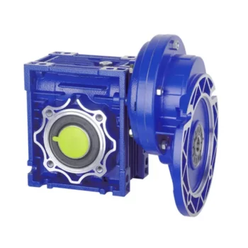
Maintenance Tips for Prolonging the Life of a Worm Gearbox
Proper maintenance is essential to ensure the longevity and reliable performance of a worm gearbox. Here are some maintenance tips to consider:
- Lubrication: Regularly check and replenish the lubricant in the gearbox. Use the recommended lubricant type and quantity specified by the manufacturer.
- Lubrication Schedule: Follow a lubrication schedule based on the operating conditions and manufacturer recommendations. Regular lubrication prevents friction, reduces wear, and dissipates heat.
- Temperature Monitoring: Keep an eye on the operating temperature of the gearbox. Excessive heat can degrade the lubricant and damage components.
- Cleanliness: Keep the gearbox and surrounding area clean from debris and contaminants. Regularly inspect and clean the gearbox exterior.
- Seal Inspection: Check for any leaks or damage to seals and gaskets. Replace them promptly to prevent lubricant leaks and contamination.
- Alignment: Ensure proper alignment between the worm and worm wheel. Misalignment can lead to increased wear and reduced efficiency.
- Torque Monitoring: Monitor the torque levels during operation. Excessive torque can cause overloading and premature wear.
- Regular Inspections: Periodically inspect all components for signs of wear, damage, or unusual noise. Replace worn or damaged parts promptly.
- Proper Usage: Operate the gearbox within its specified limits, including load, speed, and temperature. Avoid overloading or sudden changes in operating conditions.
- Expert Maintenance: If major maintenance or repairs are needed, consult the manufacturer's guidelines or seek the assistance of qualified technicians.
By following these maintenance tips and adhering to the manufacturer's recommendations, you can extend the lifespan of your worm gearbox and ensure its optimal performance over time.

How to Calculate the Input and Output Speeds of a Worm Gearbox?
Calculating the input and output speeds of a worm gearbox involves understanding the gear ratio and the principles of gear reduction. Here's how you can calculate these speeds:
- Input Speed: The input speed (N1) is the speed of the driving gear, which is the worm gear in this case. It is usually provided by the manufacturer or can be measured directly.
- Output Speed: The output speed (N2) is the speed of the driven gear, which is the worm wheel. To calculate the output speed, use the formula:
N2 = N1 / (Z1 * i)
Where:
N2 = Output speed (rpm)
N1 = Input speed (rpm)
Z1 = Number of teeth on the worm gear
i = Gear ratio (ratio of the number of teeth on the worm gear to the number of threads on the worm)
It's important to note that worm gearboxes are designed for gear reduction, which means that the output speed is lower than the input speed. Additionally, the efficiency of the gearbox, friction, and other factors can affect the actual output speed. Calculating the input and output speeds is crucial for understanding the performance and capabilities of the worm gearbox in a specific application.

Advantages of Using a Worm Reducer in Mechanical Systems
Worm reducers offer several advantages that make them suitable for various mechanical systems:
- High Gear Reduction Ratio: Worm gearboxes provide significant speed reduction, making them ideal for applications that require a high gear reduction ratio without the need for multiple gears.
- Compact Design: Worm reducers have a compact and space-saving design, allowing them to be used in applications with limited space.
- Self-Locking: Worm gearboxes exhibit self-locking properties, which means that the worm screw can prevent the worm wheel from reversing its motion. This is beneficial for applications where the gearbox needs to hold a load in place without external braking mechanisms.
- Smooth and Quiet Operation: Worm gearboxes operate with a sliding motion between the teeth, resulting in smoother and quieter operation compared to some other types of gearboxes.
- High Torque Transmission: Worm gearboxes can transmit high torque levels, making them suitable for applications that require powerful torque output.
- Heat Dissipation: The sliding action between the worm screw and the worm wheel contributes to heat dissipation, which can be advantageous in applications that generate heat during operation.
- Stable Performance: Worm reducers offer stable and reliable performance, making them suitable for continuous operation in various industrial and mechanical systems.
Despite these advantages, it's important to note that worm gearboxes also have limitations, such as lower efficiency compared to other gear types due to the sliding motion and potential for higher heat generation. Therefore, selecting the appropriate type of gearbox depends on the specific requirements and constraints of the application.
editor by CX 2023-09-15