Product Description
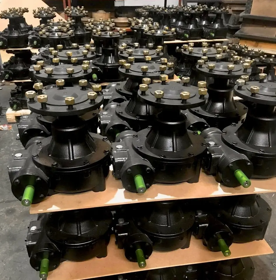
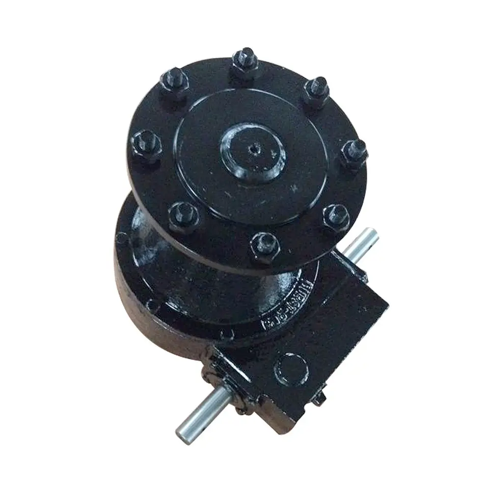
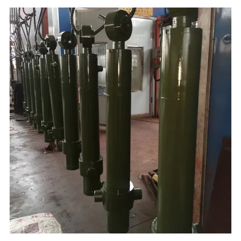
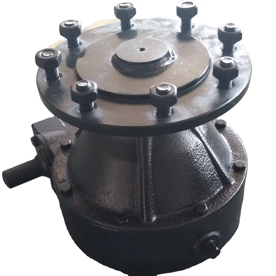
Electric Drive Center CHINAMFG Lateral Move Systems Stainless Steel Motor Housing Injection Pump Driveline Motor Gearboxes for Irrigation System
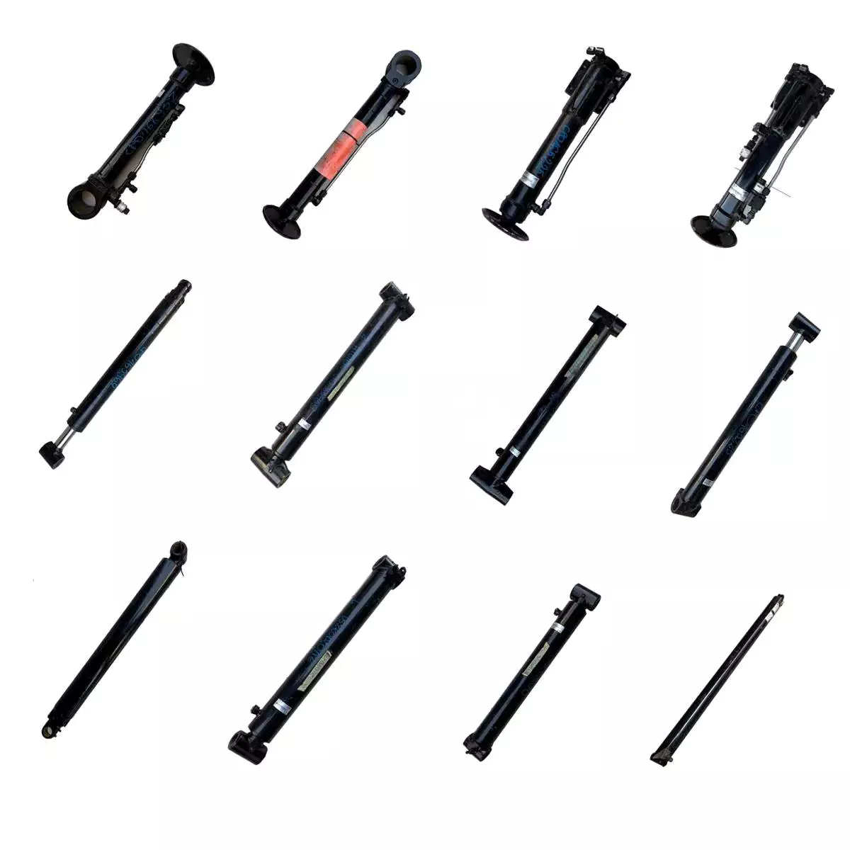
Related products:
Our Factory:
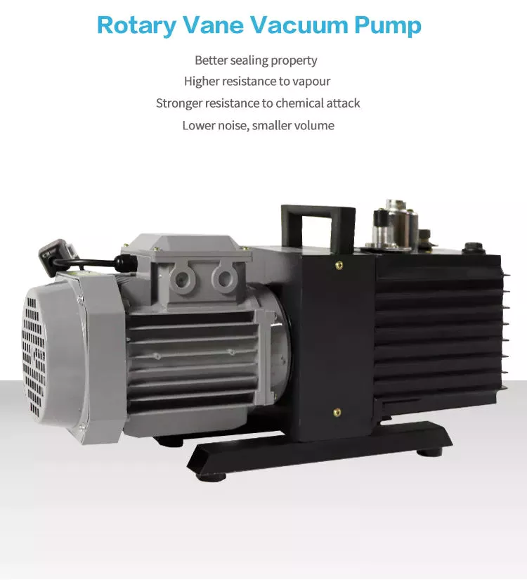
1. Shell: made of high rigidity fc-25 cast iron;
2. Gear: high purity alloy steel 20crmnt is used for quenching and tempering, carburizing, quenching and grinding;
3. Spindle: high purity alloy steel 40Cr quenching and tempering processing, with high hanging load capacity.
4. Bearing: equipped with tapered roller bearing with heavy load capacity;
5. Oil seal: imported double lip oil seal, with the ability of dust and oil leakage.
Product lubrication:
The use of proper lubricating oil for t spiral bevel gear commutator can give full play to the efficiency of the steering gear and improve its service life.
1. The initial wear period is 2 weeks or 100-200 hours. There may be a small amount of metal wear particles between them. Please clean the interior and replace it with new lubricating oil;
2. In case of long-term use, change the lubricating oil every half a year or 1000-2000 hours.
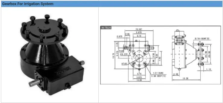
Technical parameters of T spiral bevel gear commutator:
It can be equipped with single horizontal axis, double horizontal axis, single vertical axis and double vertical axis 1:5, 1:5, 1:1, 1:5, 1:5, 1:1
Company Profile: /* March 10, 2571 17:59:20 */!function(){function s(e,r){var a,o={};try{e&&e.split(",").forEach(function(e,t){e&&(a=e.match(/(.*?):(.*)$/))&&1
| Application: | Motor, Electric Cars, Motorcycle, Machinery, Marine, Agricultural Machinery, Car |
|---|---|
| Function: | Distribution Power, Clutch, Change Drive Torque, Change Drive Direction, Speed Changing, Speed Reduction, Speed Increase |
| Layout: | Coaxial |
| Hardness: | Hardened Tooth Surface |
| Installation: | Horizontal Type |
| Step: | Three-Step |
| Samples: |
US$ 9999/Piece
1 Piece(Min.Order) | |
|---|
Compatibility with Different Types of Irrigation Pumps
Irrigation gearboxes are designed to be versatile and compatible with various types of irrigation pumps. They can be used with:
- Centrifugal Pumps: These are commonly used for irrigation due to their efficiency and simplicity. Irrigation gearboxes can easily connect to the output shaft of centrifugal pumps, allowing them to convert rotational power to the desired movement for irrigation systems.
- Positive Displacement Pumps: These pumps provide a consistent flow rate and are often used for more precise irrigation applications. Irrigation gearboxes can be integrated to ensure precise control over the movement and speed of positive displacement pumps.
- Submersible Pumps: These pumps are often used in deep wells or reservoirs. While not directly connected to irrigation gearboxes, the gearbox can control the mechanisms that adjust the position of submersible pumps in wells or reservoirs, optimizing water intake.
- Diaphragm Pumps: Diaphragm pumps are commonly used for small-scale irrigation or drip systems. Irrigation gearboxes can regulate the movement of diaphragm pumps, controlling the amount of water released.
The adaptability of irrigation gearboxes makes them suitable for various irrigation pump types, allowing farmers and agricultural operators to efficiently manage water distribution and optimize irrigation practices.
Ensuring Durability of Irrigation Gearboxes in Outdoor Environments
Manufacturers take several measures to ensure the durability of irrigation gearboxes in outdoor environments:
- Weather-Resistant Materials: Manufacturers use materials that are resistant to outdoor conditions, such as corrosion-resistant alloys and coatings to protect against moisture, UV radiation, and other environmental factors.
- Sealing and Enclosures: Irrigation gearboxes are often equipped with sealed enclosures to prevent dust, dirt, and water from entering the gearbox housing. This helps to maintain smooth operation and prevents damage to internal components.
- Gasket and O-Ring Seals: Gaskets and O-ring seals are used to create a tight seal between different components, preventing water and contaminants from entering critical areas.
- IP Ratings: Manufacturers design irrigation gearboxes with specific Ingress Protection (IP) ratings that indicate their resistance to water and dust. Higher IP ratings indicate better protection against outdoor elements.
- Proper Lubrication: Lubrication is crucial for preventing corrosion and ensuring smooth gear operation. Manufacturers select lubricants suitable for outdoor conditions and provide recommendations for regular maintenance.
- Robust Design: Gearboxes are designed to withstand the mechanical stresses associated with irrigation systems. Reinforced housing, high-quality bearings, and precision manufacturing contribute to their durability.
- Testing and Certification: Manufacturers subject irrigation gearboxes to rigorous testing under simulated outdoor conditions to ensure their performance and durability. They might also obtain certifications that verify the gearboxes' suitability for outdoor use.
These measures collectively contribute to the longevity and reliability of irrigation gearboxes in the challenging and variable conditions of outdoor agricultural environments.
Benefits of Using an Irrigation Gearbox in Irrigation Systems
Irrigation gearboxes offer several advantages when integrated into irrigation systems for agricultural purposes:
1. Efficient Water Management: Irrigation gearboxes allow precise control over water flow rates, ensuring that crops receive the right amount of water. This efficiency prevents overwatering or underwatering and optimizes water usage.
2. Uniform Water Distribution: By regulating water flow, irrigation gearboxes ensure uniform water distribution across the field. This prevents uneven crop growth and provides consistent moisture to all plants.
3. Customized Irrigation: Modern irrigation gearboxes can be programmed with specific irrigation schedules based on crop needs, weather conditions, and soil moisture levels. This customization enhances water efficiency and crop health.
4. Adaptability to Terrain: Agricultural fields often have varying slopes and terrains. Irrigation gearboxes can be adjusted to accommodate these changes, allowing water to flow evenly and reach all areas of the field.
5. Water Conservation: Precise water distribution minimizes wastage, contributing to water conservation efforts. This is particularly important in regions where water resources are scarce.
6. Increased Crop Yields: Uniform water distribution and efficient moisture management promote healthy crop growth, resulting in higher yields and improved crop quality.
7. Prevention of Waterlogging: Irrigation gearboxes help prevent waterlogging by controlling water levels. This prevents root damage and soil compaction that can occur from excessive water accumulation.
8. Reduction in Labor: Automated irrigation systems equipped with irrigation gearboxes reduce the need for manual intervention. Farmers can set up automated watering schedules, saving time and labor.
9. Environmental Sustainability: Using irrigation gearboxes to optimize water usage aligns with sustainable farming practices and reduces the environmental impact of agriculture.
10. Improved Plant Health: Consistent and controlled water distribution enhances plant health, as it minimizes stress caused by inadequate or excessive watering.
11. Enhanced Crop Management: Irrigation gearboxes enable farmers to easily manage and adjust irrigation schedules, ensuring that crops receive water at optimal times for growth.
12. Return on Investment: While the initial investment may be incurred when installing irrigation systems with gearboxes, the long-term benefits, including increased yields and resource efficiency, often result in a positive return on investment.
Irrigation gearboxes play a pivotal role in modern agricultural practices by optimizing water distribution, enhancing crop productivity, and promoting sustainable irrigation methods.


editor by CX 2024-02-02
China best 2864028 M11 Qsm11 ISM11 Cylinder Head Alternator Starting Motor Turbocharger Water Pump Blet Tensioner Cam Follower Shaft Rocker Sensor for Cylinder CZPT vacuum pump ac system
Product Description
Product Description
| Key Words: | Cummins Heand Cylinder 2864571 |
| Part Name: | Head Cylinder |
| Part No.: | 2864571 |
| Applied Engine: | M11 QSM11 ISM11 |
| Brand: | Cummins |
| Origin: | China |
| Weight: | 12.56KG |
| Size: | 31.8CM*19.4CM*19.4CM |
Detailed Photos
Packaging & Shipping
Installation Instructions
Company Profile
- Established in 2571, ZheJiang HONOR INDUSTRIAL CO.,LTD. has import and export rights. Our company fully supplies customers with genuine CHINAMFG spare parts, including fuel systems, cooling systems, lubrication systems, intake and exhaust systems, power systems. Products are widely used in mining, construction engineering, oil field, highway, CHINAMFG and other fields.
Our company also produces various types of rotary CHINAMFG picks, road milling picks, coal mining picks. We have domestic advanced vacuum brazing equipment, top-level robot equipment for robotic arm series joint, and nanotechnology spraying equipment, which can effectively ensure reliable and stable product quality. So as to create a high-end pick product that makes customers more assured and more practical. Products are widely used in highway construction, railway construction, housing construction and other industries.
Our company has a strong technical team, with top technology, rich production experience, sophisticated production equipment, advanced production process, scientific management system and high-quality after-sales service, continuing to grow and develop. "Persistence is belief, integrity is character" is our principle of action, the company will be committed to serving customers at home and a broad with high-quality products and reasonable prices for a long time.
Our Advantages
Price: When ordering in large quantities, the price is guaranteed to be the most competitive on the entire network.
Quality: Genuine parts, fake 1 loses ten.
Delivery time: In order to meet customer needs, our company reserves different models of genuine CHINAMFG spare parts inventory. No matter when and where customers have demand for CHINAMFG engine parts, we can respond quickly, except for some infrequently used parts.
FAQ
Q1: How much is the MOQ?
A: MOQ varies for different products.
Q2: Do you provide sample?
A: Samples can be provided and the cost of ordering samples shall be borne by yourself.
Q3: What is the shipping way?
A: Shipping way is determined according to customer needs, order quantity and product category.
Q4: How long is the delivery time?
A: Picking spot. CHINAMFG products according to supplier, most of the spot or production cycle is about 7 days. The shipping cycle is determined by the shipping method.
Q5: What does the packaging look like?
A: CHINAMFG product packaging is determined by mutual negotiation. The packaging of the picks is subject to our company.
Q6: How to pay?
A: Multiple ways. Mainly T/T.
Q7: What is the after-sales guarantee?
A: Abnormal damage can be claimed. Our company continues to provide technical advice.
Cummins Engine Parts
ZheJiang Honor Company can provide you with pure and high-quality CHINAMFG engine parts of various models. Parts are divided into overhaul parts, common parts, kits, etc. We have a professional and experienced technical service and sales team. According to the engine model you provide, part name or part number, we will be able to respond quickly to your needs.
Cummins common parts
Common parts refer to the parts that may need to be replaced due to damage during routine maintenance or during engine work.
2864571 M11 QSM11 ISM11 Cylinder Head Alternator Starting motor Turbocharger water pump Blet Tensioner Cam Follower Shaft Rocker Sensor for Cylinder Cummins
| Certification: | ISO9001, E-Mark, RoHS, TS16949 |
|---|---|
| Standard Component: | Standard Component |
| Technics: | Push |
| Material: | Iron |
| Type: | Cooler |
| for: | Cummins Engine |
| Customization: |
Available
|
|
|---|
How do hydraulic cylinders handle the challenges of precise positioning and control?
Hydraulic cylinders are designed to handle the challenges of precise positioning and control with a combination of engineering principles and advanced control systems. These challenges often arise in applications where accurate and controlled movements are required, such as in industrial automation, construction, and material handling. Here's a detailed explanation of how hydraulic cylinders overcome these challenges:
1. Fluid Power Control:
- Hydraulic cylinders utilize fluid power control to achieve precise positioning and control. The hydraulic system consists of a hydraulic pump, control valves, and hydraulic fluid. By regulating the flow of hydraulic fluid into and out of the cylinder, operators can control the speed, direction, and force exerted by the cylinder. The fluid power control allows for smooth and accurate movements, enabling precise positioning of the hydraulic cylinder and the attached load.
2. Control Valves:
- Control valves play a crucial role in handling the challenges of precise positioning and control. These valves are responsible for directing the flow of hydraulic fluid within the system. They can be manually operated or electronically controlled. Control valves allow operators to adjust the flow rate of the hydraulic fluid, controlling the speed of the cylinder's movement. By modulating the flow, operators can achieve fine control over the positioning of the hydraulic cylinder, enabling precise and accurate movements.
3. Proportional Control:
- Hydraulic cylinders can be equipped with proportional control systems, which offer enhanced precision in positioning and control. Proportional control systems utilize electronic feedback and control algorithms to precisely regulate the flow and pressure of the hydraulic fluid. These systems provide accurate and proportional control over the movement of the hydraulic cylinder, allowing for precise positioning at various points along its stroke length. Proportional control enhances the cylinder's ability to handle complex tasks that require precise movements and control.
4. Position Feedback Sensors:
- To achieve precise positioning, hydraulic cylinders often incorporate position feedback sensors. These sensors provide real-time information about the position of the cylinder's piston rod. Common types of position feedback sensors include potentiometers, linear variable differential transformers (LVDTs), and magnetostrictive sensors. By continuously monitoring the position, the feedback sensors enable closed-loop control, allowing for accurate positioning and control of the hydraulic cylinder. The feedback information is used to adjust the flow of hydraulic fluid to achieve the desired position accurately.
5. Servo Control Systems:
- Advanced hydraulic systems employ servo control systems to handle the challenges of precise positioning and control. Servo control systems combine electronic control, position feedback sensors, and proportional control valves to achieve high levels of accuracy and responsiveness. The servo control system continuously compares the desired position with the actual position of the hydraulic cylinder and adjusts the flow of hydraulic fluid to minimize any positional error. This closed-loop control mechanism enables the hydraulic cylinder to maintain precise positioning and control, even under varying loads or external disturbances.
6. Integrated Automation:
- Hydraulic cylinders can be integrated into automated systems to achieve precise positioning and control. In such setups, the hydraulic cylinders are controlled by programmable logic controllers (PLCs) or other automation controllers. These controllers receive input signals from various sensors and use pre-programmed logic to command the hydraulic cylinder's movements. The integration of hydraulic cylinders into automated systems allows for precise and repeatable positioning and control, enabling complex sequences of movements to be executed with high accuracy.
7. Advanced Control Algorithms:
- Advancements in control algorithms have also contributed to the precise positioning and control of hydraulic cylinders. These algorithms, such as PID (Proportional-Integral-Derivative) control, adaptive control, and model-based control, enable sophisticated control strategies to be implemented. These algorithms consider factors such as load variations, system dynamics, and environmental conditions to optimize the control of hydraulic cylinders. By employing advanced control algorithms, hydraulic cylinders can compensate for disturbances and achieve precise positioning and control over a wide range of operating conditions.
In summary, hydraulic cylinders overcome the challenges of precise positioning and control through the use of fluid power control, control valves, proportional control, position feedback sensors, servo control systems, integrated automation, and advanced control algorithms. By combining these elements, hydraulic cylinders can achieve accurate and controlled movements, enabling precise positioning and control in various applications. These capabilities are essential for industries that require high precision and repeatability in their operations, such as industrial automation, robotics, and material handling.
What considerations are important when selecting hydraulic cylinders for mobile equipment?
To select hydraulic cylinders for mobile equipment, several important considerations need to be taken into account. Here are the key factors to consider:
- Load Capacity: Determine the maximum load or force that the hydraulic cylinder will need to support. This includes both the static load and any dynamic or shock loads that may be encountered during operation.
- Stroke Length: Consider the required stroke length, which is the distance the hydraulic cylinder can extend and retract. Ensure that the stroke length is sufficient for the specific application and range of motion needed.
- Operating Pressure: Determine the maximum operating pressure required for the hydraulic system. This will depend on the load and the specific application. Select a hydraulic cylinder with a pressure rating that exceeds the maximum operating pressure to ensure safety and durability.
- Mounting Style: Consider the available space and the mounting requirements of the mobile equipment. Hydraulic cylinders come in various mounting styles, such as flange, trunnion, clevis, and pivot, among others. Choose a mounting style that is compatible with the equipment and provides the necessary support and stability.
- Size and Weight: Take into account the physical dimensions and weight of the hydraulic cylinder. Ensure that it can fit within the available space and that the equipment can support its weight without compromising performance or safety.
- Speed and Precision: Evaluate the required speed and precision of the hydraulic cylinder's movement. Different cylinder designs and configurations can affect the speed and accuracy of motion. Consider factors such as cylinder bore size, rod diameter, and the presence of cushioning or dampening features.
- Environmental Factors: Assess the operating environment of the mobile equipment. Consider factors such as temperature extremes, exposure to moisture, dust, and chemicals. Select hydraulic cylinders with appropriate seals and coatings that can withstand the environmental conditions and prevent corrosion or damage.
- Reliability and Maintenance: Consider the reliability and maintenance requirements of the hydraulic cylinders. Look for reputable manufacturers that provide high-quality products with a proven track record. Evaluate factors such as expected service life, availability of spare parts, and ease of maintenance.
- Cost: Finally, consider the cost of the hydraulic cylinders, including the initial purchase price, installation costs, and long-term maintenance expenses. While it is essential to find a cost-effective solution, prioritize quality and performance to ensure safe and efficient operation.
Can you provide real-world examples of machinery that heavily rely on hydraulic cylinders?
Hydraulic cylinders are widely used in various industries and applications due to their ability to provide powerful and precise linear motion. They play a crucial role in enabling the operation of heavy machinery that requires controlled force and movement. Here are some real-world examples of machinery that heavily rely on hydraulic cylinders:
1. Construction Equipment:
- Hydraulic cylinders are extensively used in construction machinery, such as excavators, bulldozers, loaders, and cranes. These machines rely on hydraulic cylinders to perform tasks like lifting heavy loads, extending and retracting booms, tilting buckets, and controlling the movement of various components. Hydraulic cylinders provide the power and precision required to handle the demanding conditions and heavy loads encountered in construction projects.
2. Agricultural Machinery:
- Many agricultural machines, including tractors, combine harvesters, and sprayers, utilize hydraulic cylinders for critical operations. Hydraulic cylinders are used to control the movement of attachments, such as front loaders, backhoes, and plows. They enable functions like lifting and lowering implements, adjusting cutting heights, and controlling the positioning of harvesting equipment. Hydraulic cylinders enhance efficiency and productivity in agricultural operations.
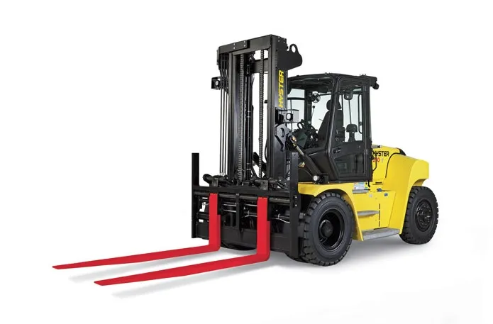
3. Material Handling Equipment:
- Hydraulic cylinders are integral components of material handling equipment, such as forklifts, pallet jacks, and cranes. These machines rely on hydraulic cylinders to lift and lower loads, tilt platforms or forks, and control the movement of lifting mechanisms. Hydraulic cylinders provide the necessary strength and precision to handle heavy loads and ensure safe and efficient material handling operations.
4. Industrial Machinery:
- Various industrial machinery and equipment heavily rely on hydraulic cylinders for critical functions. Examples include hydraulic presses, injection molding machines, metal-forming machines, and hydraulic-powered robots. Hydraulic cylinders enable precise control of force and movement in these applications, allowing for accurate shaping, pressing, and assembly processes.
5. Mining Equipment:
- Hydraulic cylinders are extensively used in mining machinery and equipment. Underground mining machines, such as continuous miners and longwall shearers, utilize hydraulic cylinders for cutting, shearing, and roof support operations. Surface mining equipment, including hydraulic shovels, draglines, and haul trucks, rely on hydraulic cylinders for tasks like bucket movement, boom extension, and vehicle suspension.
6. Automotive Industry:
- The automotive industry extensively utilizes hydraulic cylinders in various applications. Hydraulic cylinders are employed in vehicle suspension systems, power steering systems, convertible tops, and hydraulic brake systems. They enable smooth and controlled movement, precise steering, and efficient braking in automobiles.
7. Aerospace and Aviation:
- Hydraulic cylinders are utilized in aerospace and aviation applications, such as aircraft landing gear systems, wing flaps, and cargo handling equipment. Hydraulic cylinders provide the necessary force and control for extending and retracting landing gear, adjusting wing flaps, and operating cargo doors, ensuring safe and reliable aircraft operations.
8. Marine and Offshore Industry:
- Hydraulic cylinders are essential components in marine and offshore equipment, including ship cranes, winches, and hydraulic-powered anchor systems. They enable lifting, lowering, and positioning of heavy loads, as well as the control of various marine equipment.
These are just a few examples of machinery and industries that heavily rely on hydraulic cylinders. The versatility, power, and precise control offered by hydraulic cylinders make them indispensable in a wide range of applications, where controlled linear motion and force are essential.


editor by CX 2023-10-29
China factory Original Wheel Loader Spare Parts Hydraulic Cylinder Xt870.3.1.2.11 for Wheel Loader/Grader Motor vacuum pump ac
Product Description
Original Wheel Loader Spare Parts Hydraulic Cylinder XT870.3.1.2.11
|
Part Name |
Hydraulic Cylinder |
Brand Name |
|
|
Part Number |
XT870.3.1.2.11 |
Application |
Wheel Loader |
|
Mini Order |
One Set/ Piece |
Packing |
Carton,Wooden Box, Pallet |
|
Supply Ability |
10000 Pieces |
OEM |
Available |
|
Quality Standard |
100% Tested |
Quality Certification |
ISO,CCC,GSO,CE,SGS,TUV |
|
Condition |
New |
Payment Terms |
L/C, T/T, Western Union,Paypal |
|
Origin |
China |
Loading Port |
Any Port In China |
Company Information / About Us
ZheJiang CHINAMFG VEHICLE TRADING CO., LTD (HOKA VEHICLE hereafter in short) has been engaged in the heavy duty truck industry for more than 15 years. With the professional team and first class design and production experience and market capacity, CHINAMFG VEHICLE has exported and delivered more than 5,000 units heavy duty trucks to countries across Africa Middle East, Southeast Asia and South America.
HOKA VEHILCE maintains dealership and distribution authorization from manufacturer including SINOTRUK, SHACMAN, FOTON, CIMC, SHENGRUN, HELI, etc. Our main products range from Dump truck, Tractor Truck, Concrete Mixer, Truck Van, Truck Lorry Truck, Off-road Dump, Truck Tanker, Truck Mounted Cranes, trailer tanker, trailers and all other kinds of modified trucks.
HOKA VEHILCE, we transport your cargos, we deliver the world, we carry your dreams!
Why Choose Us
Worldwide Sales, Marketing and Service Network
During the past 15 years, we have exported over 5,000 units of different kinds of heavy duty trucks to over 50 countries in Africa, Middle East, Southeast Asia, and South America. Our overseas authorized truck dealers and service dealers are all around the world.
Wide Ranges of Various Modified Trucks with Different Applications
Our main products range from Dump Truck, Tractor Truck, Concrete Mixer Truck, Van Truck, Lorry Truck, Off-road Dump Truck, Tanker Truck, Truck Mounted Cranes, trailer, tanker trailers and all other kinds of modified trucks. We can design, produce and supply our customers with any special vehicle.
Flexible Payment Terms for Different Trucks and Business
Besides traditional payment terms such as TT, LC, we still offer our stable and long-term partners with various financial support and credit payment terms at different periods.
Excellent and Outstanding After Sales Service
Our professional technicians and mechanics and parts staff always concentrate all our products and our customers. Top Starting Point, High Quality and Worry-free Service is our promise to all our customers.
High Efficiency is One of Our Goal and Promise to Our Customers
We will be always with our customers whenever and wherever we are. All problems and questions shall be solved by our end at the first time. Customer priority outstands without any doubt.
Latest Truck Development and Trends Shall Be Delivered Regularly
We have abundant technical team, familiar with local and major exporter product standards. Our customers will be regularly updated with the latest truck development and trends in China and other countries.
Who we are?
The most professional truck and spare parts distributor in China;
The leading truck and spare parts exporter in China;
The most comprehensive truck and spare parts solution provider in China;
The most worry-free and most satisfactory and reputable supplier for you in China.
We will never let you down if you choose us.
Contact us:
Sales Manager: Lock Wu
| Type: | Wheel Loader |
|---|---|
| Muffler Type: | Wheel Loader |
| Deck: | Wheel Loader |
| OEM: | Available |
| Stock: | Available |
| Min. Order Quantity: | 1 |
| Samples: |
US$ 441/Piece
1 Piece(Min.Order) | |
|---|
| Customization: |
Available
|
|
|---|
What advancements in hydraulic cylinder technology have improved energy efficiency?
Advancements in hydraulic cylinder technology have led to significant improvements in energy efficiency, allowing hydraulic systems to operate more efficiently and reduce energy consumption. These advancements aim to minimize energy losses, optimize system performance, and enhance overall efficiency. Here's a detailed explanation of some key advancements in hydraulic cylinder technology that have improved energy efficiency:
1. Efficient Hydraulic Circuit Design:
- The design of hydraulic circuits has evolved to improve energy efficiency. Advancements in circuit design techniques, such as load-sensing, pressure-compensated systems, or variable displacement pumps, help match the hydraulic power output to the actual load requirements. These designs reduce unnecessary energy consumption by adjusting the flow and pressure levels according to the system demands, rather than operating at a fixed high pressure.
2. High-Efficiency Hydraulic Fluids:
- The development of high-efficiency hydraulic fluids, such as low-viscosity or synthetic fluids, has contributed to improved energy efficiency. These fluids offer lower internal friction and reduced resistance to flow, resulting in decreased energy losses within the system. Additionally, advanced fluid additives and formulations enhance lubrication properties, reducing friction and optimizing the overall efficiency of hydraulic cylinders.
3. Advanced Sealing Technologies:
- Seal technology has advanced significantly, leading to improved energy efficiency in hydraulic cylinders. High-performance seals, such as low-friction or low-leakage seals, minimize internal leakage and friction losses. Reduced internal leakage helps maintain system pressure more effectively, resulting in less energy waste. Additionally, innovative sealing materials and designs enhance durability and extend seal life, reducing the need for frequent maintenance and replacement.
4. Electro-Hydraulic Control Systems:
- The integration of advanced electro-hydraulic control systems has greatly contributed to energy efficiency improvements. By combining electronic control with hydraulic power, these systems enable precise control over cylinder operation, optimizing energy usage. Proportional or servo valves, along with position or force feedback sensors, allow for accurate and responsive control, ensuring that hydraulic cylinders operate at the required level of performance while minimizing energy waste.
5. Energy Recovery Systems:
- Energy recovery systems, such as hydraulic accumulators, have been increasingly utilized to improve energy efficiency in hydraulic cylinder applications. Accumulators store excess energy during low-demand periods and release it when there is a peak demand, reducing the need for the hydraulic pump to provide the full power continuously. By utilizing stored energy, these systems can significantly reduce energy consumption and improve overall system efficiency.
6. Smart Monitoring and Control:
- Advancements in smart monitoring and control technologies have enabled real-time monitoring of hydraulic systems, allowing for optimized energy usage. Integrated sensors, data analytics, and control algorithms provide insights into system performance and energy consumption, enabling operators to make informed decisions and adjustments. By identifying inefficiencies or suboptimal operating conditions, energy consumption can be minimized, leading to improved energy efficiency.
7. System Integration and Optimization:
- The integration and optimization of hydraulic systems as a whole have played a significant role in improving energy efficiency. By considering the entire system layout, component sizing, and interaction between different elements, engineers can design hydraulic systems that operate in the most energy-efficient manner. Proper sizing of components, minimizing pressure drops, and reducing unnecessary piping or valve restrictions all contribute to improved energy efficiency of hydraulic cylinders.
8. Research and Development:
- Ongoing research and development efforts in the field of hydraulic cylinder technology continue to drive energy efficiency advancements. Innovations in materials, component design, system modeling, and simulation techniques help identify areas for improvement and optimize energy usage. Additionally, collaboration between industry stakeholders, research institutions, and regulatory bodies fosters the development of energy-efficient hydraulic cylinder technologies.
In summary, advancements in hydraulic cylinder technology have resulted in notable improvements in energy efficiency. Efficient hydraulic circuit designs, high-efficiency hydraulic fluids, advanced sealing technologies, electro-hydraulic control systems, energy recovery systems, smart monitoring and control, system integration and optimization, as well as ongoing research and development efforts, all contribute to reducing energy consumption and enhancing the overall energy efficiency of hydraulic cylinders. These advancements not only benefit the environment but also offer cost savings and improved performance in various hydraulic applications.
Ensuring Stable Performance of Hydraulic Cylinders Under Fluctuating Loads
Hydraulic cylinders are designed to provide stable performance even under fluctuating loads. They achieve this through various mechanisms and features that allow for efficient load control and compensation. Let's explore how hydraulic cylinders ensure stable performance under fluctuating loads:
- Piston Design: The piston inside the hydraulic cylinder plays a crucial role in load control. It is typically equipped with seals and rings that prevent leakage of hydraulic fluid and ensure effective transfer of force. The piston design may incorporate features such as stepped or tandem pistons, which provide enhanced load-bearing capabilities and improved stability by distributing the load across multiple surfaces.
- Cylinder Cushioning: Hydraulic cylinders often incorporate cushioning mechanisms to minimize the impact and shock caused by fluctuating loads. Cushioning can be achieved through various methods, such as adjustable cushion screws, hydraulic cushioning valves, or elastomeric cushioning rings. These mechanisms slow down the piston's movement near the end of the stroke, reducing the impact and preventing sudden stops that could lead to instability.
- Pressure Compensation: Fluctuating loads can result in pressure variations within the hydraulic system. To ensure stable performance, hydraulic cylinders are equipped with pressure compensation mechanisms. These mechanisms maintain a consistent pressure level in the system, regardless of load changes. Pressure compensation can be achieved through the use of pressure relief valves, compensating pistons, or pressure-compensated flow control valves.
- Flow Control: Hydraulic cylinders often incorporate flow control valves to regulate the speed of the cylinder's movement. By controlling the flow rate of hydraulic fluid, the cylinder's motion can be adjusted to match the changing load conditions. Flow control valves allow for smooth and controlled movement, preventing abrupt changes that could lead to instability.
- Feedback Systems: To ensure stable performance under fluctuating loads, hydraulic cylinders can be integrated with feedback systems. These systems provide real-time information on the cylinder's position, velocity, and force. By continuously monitoring these parameters, the hydraulic system can make immediate adjustments to maintain stability and compensate for load fluctuations. Feedback systems can include position sensors, pressure sensors, or load sensors, depending on the specific application.
- Proper Sizing and Selection: Ensuring stable performance under fluctuating loads starts with proper sizing and selection of hydraulic cylinders. It is crucial to choose cylinders with appropriate bore size, rod diameter, and stroke length to match the anticipated load conditions. Oversized or undersized cylinders can lead to instability and reduced performance. Proper sizing also involves considering factors such as the required force, speed, and duty cycle of the application.
In summary, hydraulic cylinders ensure stable performance under fluctuating loads through features such as piston design, cushioning mechanisms, pressure compensation, flow control, feedback systems, and proper sizing and selection. These mechanisms and considerations allow hydraulic cylinders to provide consistent and controlled movement, even in dynamic load conditions, resulting in reliable and stable performance.
How do hydraulic cylinders generate force and motion using hydraulic fluid?
Hydraulic cylinders generate force and motion by utilizing the principles of fluid mechanics, specifically Pascal's law, in conjunction with the properties of hydraulic fluid. The process involves the conversion of hydraulic energy into mechanical force and linear motion. Here's a detailed explanation of how hydraulic cylinders achieve this:
1. Pascal's Law:
- Hydraulic cylinders operate based on Pascal's law, which states that when pressure is applied to a fluid in a confined space, it is transmitted equally in all directions. In the context of hydraulic cylinders, this means that when hydraulic fluid is pressurized, the force is evenly distributed throughout the fluid and transmitted to all surfaces in contact with the fluid.
2. Hydraulic Fluid and Pressure:
- Hydraulic systems use a specialized fluid, typically hydraulic oil, as the working medium. This fluid is stored in a reservoir and circulated through the system by a hydraulic pump. The pump pressurizes the fluid, creating hydraulic pressure that can be controlled and directed to various components, including hydraulic cylinders.
3. Cylinder Design and Components:
- Hydraulic cylinders consist of several key components, including a cylindrical barrel, a piston, a piston rod, and various seals. The barrel is a hollow tube that houses the piston and allows for fluid flow. The piston divides the cylinder into two chambers: the rod side and the cap side. The piston rod extends from the piston and provides a connection point for external loads. Seals are used to prevent fluid leakage and maintain hydraulic pressure within the cylinder.
4. Fluid Input and Motion:
- To generate force and motion, hydraulic fluid is directed into one side of the cylinder, creating pressure on the corresponding surface of the piston. This pressure is transmitted through the fluid to the other side of the piston.
5. Force Generation:
- The force generated by a hydraulic cylinder is a result of the pressure applied to a specific surface area of the piston. The force exerted by the hydraulic cylinder can be calculated using the formula: Force = Pressure × Area. The area is determined by the diameter of the piston or the piston rod, depending on which side of the cylinder the fluid is acting upon.
6. Linear Motion:
- As the pressurized hydraulic fluid acts on the piston, it generates a force that moves the piston in a linear direction within the cylinder. This linear motion is transferred to the piston rod, which extends or retracts accordingly. The piston rod can be connected to external components or machinery, allowing the generated force to perform various tasks, such as lifting, pushing, pulling, or controlling mechanisms.
7. Control and Regulation:
- The force and motion generated by hydraulic cylinders can be controlled and regulated by adjusting the flow of hydraulic fluid into the cylinder. By regulating the flow rate, pressure, and direction of the fluid, the speed, force, and direction of the cylinder's movement can be precisely controlled. This control allows for accurate positioning, smooth operation, and synchronization of multiple cylinders in complex machinery.
8. Return and Recirculation of Fluid:
- After the hydraulic cylinder completes its stroke, the hydraulic fluid on the opposite side of the piston needs to be returned to the reservoir. This is typically achieved through hydraulic valves that control the flow direction, allowing the fluid to return and be recirculated in the system for further use.
In summary, hydraulic cylinders generate force and motion by utilizing the principles of Pascal's law. Pressurized hydraulic fluid acts on the piston, creating force that moves the piston in a linear direction. This linear motion is transferred to the piston rod, allowing the generated force to perform various tasks. By controlling the flow of hydraulic fluid, the force and motion of hydraulic cylinders can be precisely regulated, contributing to their versatility and wide range of applications in machinery.
editor by CX 2023-10-15
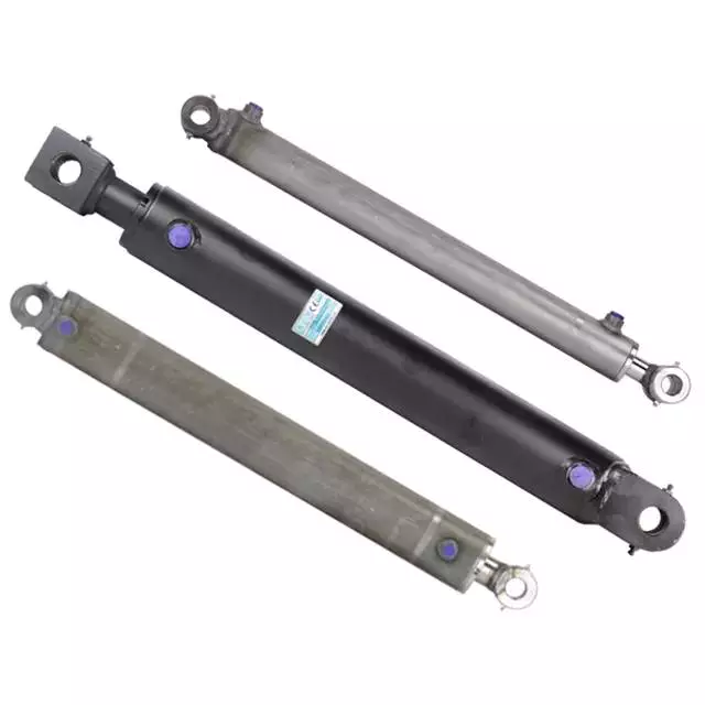
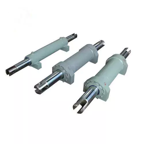
China manufacturer Hydraulic Motor Forklift Dump Truck Double Acting Double Acting Small Hydraulic Cylinder vacuum pump brakes
Product Description
Products Description
|
Product Name |
HSG Series Hydraulic Cylinder |
|||
|
Work Press |
7/14/16/21/31.5MPa 37.5/63MPa Can be Customized |
|||
|
Material |
Aluminum,Cast Iron,45mnb Steel,Stainless Steel |
|||
|
Bore Size |
40mm--320mm,Customizable |
|||
|
Shaft Diameter |
20mm--220mm,Customizable |
|||
|
Stroke Length |
30mm--14100mm,Customizable |
|||
|
Rod Surface Hardness |
HRC48-54 |
|||
|
Paint Color |
Black,Yellow,Blue,Brown,Customizable |
|||
|
Mounting |
Earring,Flange,Clevis.Foot,Trunnion,Customizable |
|||
|
Warrenty |
1 Year |
|||
|
MOQ |
1 Piece |
|||
|
Delivery Time |
7-15 Days,Also depands on specific demands |
|||
|
Certification |
ISO9001,CE |
|||
Company Profile
QIANGLIN HYDRAULIC MACHINERY CO., LTD
| QiangLin is a professional hydraulic equipment manufacturer, mainly engaged in hydraulic system design, manufacture, installation, transformation, sales, and technical services. Our manufacturing facilities are certified to the ISO 9001 standard. We are an approved supplier to many equipment manufacturers in China. We are also partners with many customers from America, Canada, Australia, Germany, England, and other European Countries. Product quality, shorter delivery time, and customer satisfaction are our long-term commitments to our CHINAMFG customers. Hope to be your partner. |
FAQ:
Q1: Are you a trading company or a manufacturer?
A: We have our own factory.
Q2: Are you able to make Non-standard or customized products?
A: Yes, we can.
Q3: How long is your delivery time?
A: Normally, the delivery time is 7 days if we have stock, 15-30 working days if we don't. but it
also depends on the product
requirements and quantity.
Q4: Do you provide samples? are the samples free or not?
A: Yes, we can provide samples, but they are not free of charge.
Q5: What are your payment terms?
A: 30% deposit T/T or Irrevocable L/C at sight, If you have any questions, please feel free to
contact us.
Q6: What are your After-sales services?
A: Before shipment, Each individual product will be strictly inspected on our factory QC Process
System. In addition, We have a
Customer Service team to respond to customers' questions within 12 hours. Being helpful in
solving customers' problems is always our goal.
| Certification: | CE, ISO9001 |
|---|---|
| Pressure: | High Pressure |
| Work Temperature: | Normal Temperature |
| Customization: |
Available
|
|
|---|
.shipping-cost-tm .tm-status-off{background: none;padding:0;color: #1470cc}
|
Shipping Cost:
Estimated freight per unit. |
about shipping cost and estimated delivery time. |
|---|
| Payment Method: |
|
|---|---|
|
Initial Payment Full Payment |
| Currency: | US$ |
|---|
| Return&refunds: | You can apply for a refund up to 30 days after receipt of the products. |
|---|
Can hydraulic cylinders be used in rough terrain forklifts?
Yes, hydraulic cylinders can be used in rough terrain forklifts. Hydraulic systems, including hydraulic cylinders, are an essential component of rough terrain forklifts and play a crucial role in their operation. Here's an explanation of their use:
Rough terrain forklifts are specifically designed to operate in challenging outdoor environments, such as construction sites, lumber yards, and agricultural settings. These forklifts are equipped with features that allow them to navigate uneven terrain, slopes, and other rough surfaces. Hydraulic cylinders are integral to their performance in the following ways:
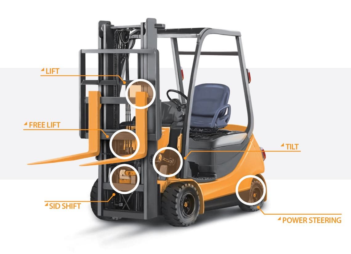
1. Lifting Functionality:
The hydraulic cylinder in a rough terrain forklift is responsible for lifting and lowering the load-carrying forks. It provides the necessary force to elevate heavy loads to the desired height. The hydraulic system allows precise control over the lifting speed and positioning, enabling efficient material handling even on rough and uneven surfaces.
2. Suspension System:
Rough terrain forklifts are equipped with a suspension system that helps absorb shocks and vibrations during operation. Hydraulic cylinders are often used as part of the suspension system to provide damping and improve ride comfort. These cylinders help cushion the impact of uneven terrain, reducing the transfer of vibrations to the forklift and the load being carried.
3. Stability and Balance:
Hydraulic cylinders contribute to the stability and balance of rough terrain forklifts. They are used to control the extension and retraction of the mast assembly, which supports the forks and the load. By adjusting the mast height and angle, the cylinders help maintain stability and balance, especially when operating on slopes or uneven ground.
4. Steering and Maneuverability:
Some rough terrain forklifts utilize hydraulic cylinders in their steering mechanisms. These cylinders assist in turning and maneuvering the forklift, allowing it to navigate through tight spaces and negotiate obstacles on rough terrain. The hydraulic system provides the necessary power and control for smooth and precise steering operations.
Overall, hydraulic cylinders are essential components of rough terrain forklifts. They enable the lifting functionality, contribute to the suspension system for improved ride comfort, help maintain stability and balance, and assist in steering and maneuverability. By utilizing hydraulic power, these forklifts can effectively handle the challenges of rough outdoor environments and ensure efficient material handling operations.
In summary, hydraulic cylinders are indeed used in rough terrain forklifts. Their presence in these forklifts enables reliable lifting, enhances stability and balance, improves ride comfort through suspension systems, and assists in steering and maneuverability on uneven surfaces. The use of hydraulic technology is instrumental in achieving optimal performance and productivity in rough terrain applications.
How does a forklift hydraulic cylinder handle variations in seal technology?
A forklift hydraulic cylinder is designed to handle variations in seal technology to ensure effective sealing and reliable performance. Here's an explanation of how it achieves this:
The hydraulic cylinder's ability to accommodate different seal technologies is essential for maintaining hydraulic fluid integrity and preventing leakage. The cylinder handles variations in seal technology through the following mechanisms:
1. Seal Compatibility:
Forklift hydraulic cylinders are designed to be compatible with various types of seal technologies. Different seal materials and designs are available, such as O-rings, lip seals, and composite seals. The cylinder is manufactured with precise dimensions and tolerances to accommodate the specific seal technology being used. This compatibility ensures a proper fit and seal, regardless of the seal technology employed.
2. Material Selection:
The choice of cylinder material is also crucial in handling variations in seal technology. Different seal materials have varying compatibility with specific cylinder materials. Forklift hydraulic cylinders are typically constructed using materials such as steel or aluminum alloys, which offer excellent compatibility with a wide range of seal technologies. The cylinder material is selected to work harmoniously with different seal materials, ensuring reliable sealing performance.
3. Seal Design and Construction:
The design and construction of seals in the hydraulic cylinder are optimized to accommodate variations in seal technology. Seal manufacturers develop seals with specific features and characteristics tailored to different applications. These features may include improved sealing lip geometry, advanced materials with enhanced wear resistance, and specialized sealing mechanisms. The cylinder is designed to accommodate these variations, providing the necessary space and support for the specific seal technology being utilized.
4. Testing and Quality Control:
Hydraulic cylinders undergo rigorous testing and quality control processes to ensure seal compatibility and performance. During manufacturing, seals are inspected for proper fit, dimensions, and sealing integrity. The hydraulic system is also subjected to pressure and leakage tests to verify the effectiveness of the seals and overall system performance. These testing and quality control measures help identify any issues related to seal technology and allow for necessary adjustments or improvements.
In summary, a forklift hydraulic cylinder handles variations in seal technology through seal compatibility, appropriate material selection, seal design and construction, and rigorous testing and quality control. These measures ensure that the cylinder can effectively accommodate different seal technologies, providing reliable sealing performance and preventing hydraulic fluid leakage.
What is a forklift hydraulic cylinder and how does it work?
A forklift hydraulic cylinder is a crucial component in the hydraulic system of a forklift. It is responsible for generating the force required to lift and lower the load. Here's a detailed explanation of its function and operation:
Function:
A forklift hydraulic cylinder is designed to convert hydraulic pressure into linear force. It consists of a cylindrical barrel, a piston, piston rod, seals, and ports for hydraulic fluid entry and exit. The cylinder is usually mounted vertically within the forklift's mast assembly.
Operation:
The hydraulic cylinder operates based on the principle of Pascal's law, which states that when pressure is applied to a fluid in an enclosed system, the pressure is transmitted equally in all directions.
When the operator activates the forklift's hydraulic control, hydraulic fluid (usually oil) is pressurized and directed into the cylinder through the inlet port. The pressurized fluid enters one side of the cylinder, pushing the piston and piston rod upwards.
As the piston rod extends, it applies force to the load-bearing structure of the forklift, such as the mast or the lifting mechanism. This force enables the forklift to lift heavy loads to the desired height.
Conversely, when the operator releases the hydraulic control, the hydraulic fluid is allowed to exit the cylinder through the outlet port. The fluid flows back into the hydraulic reservoir, and the weight of the load or a counterbalance system helps lower the piston and piston rod.
The hydraulic cylinder's movement is controlled by the operator through the forklift's hydraulic control system, which regulates the flow of hydraulic fluid into and out of the cylinder. By adjusting the flow rate and direction, the operator can control the speed and direction of the cylinder's extension and retraction.
The seals within the hydraulic cylinder prevent fluid leakage and ensure efficient operation. They help maintain the pressure inside the cylinder, allowing the hydraulic system to generate the necessary force consistently.
In summary, a forklift hydraulic cylinder is a hydraulic device that converts hydraulic pressure into linear force. It operates based on Pascal's law, using pressurized hydraulic fluid to extend and retract the piston rod, enabling the forklift to lift and lower heavy loads.
editor by CX 2023-10-13
China best Electric Drive Center CZPT Lateral Move Systems Stainless Steel Motor Housing Injection Pump Driveline Motor Gearboxes for Irrigation System gearbox assembly
Product Description
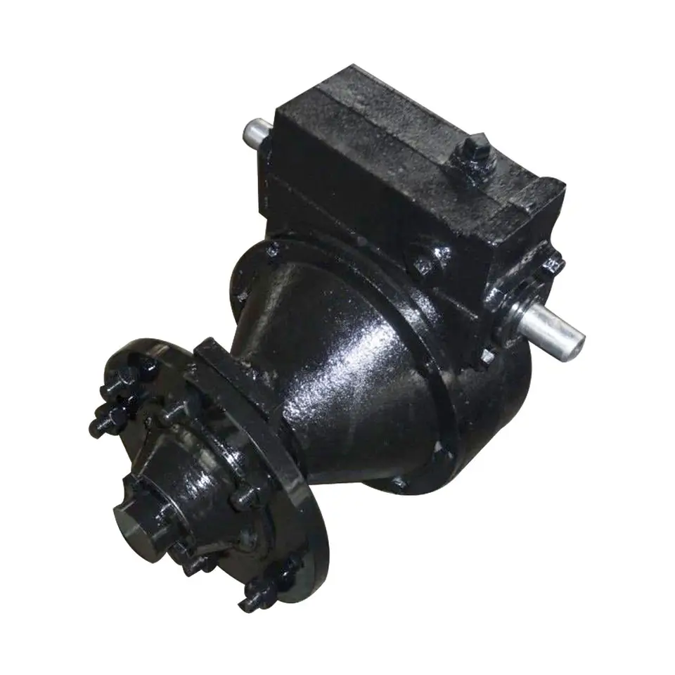
electric drive Center CHINAMFG lateral move Systems Stainless steel motor housing injection pump Driveline Motor gearboxes for Irrigation System
| Power Saver III: Application: 480/360 Volt A.C. Electric motors with 95% Efficient planetary speed reducing gearboxes for power transmission of electric drive Center CHINAMFG / lateral move Systems. Also uses in power transmission for injection pump on chemical applicators.
Ratios Include: |
GEAR MATERIALS
20CrMnTi/20CrMnMo for your choice
CASTINGS MATERIALS
Gray cast iron HT250 according to standard GB/T 1348-2009 Ductile iron QT450-10 according to standard GB/T 1348-2009 Cast steel ZG310-570 according to standard GB/T 5613-2014
SHAFTS MATERIALS
40Cr,45#,20CrMnTi,20CrMnMo for your choice according to your request.
POWER To ensure the correct use of the product we recommand to pay attention to the specifications mentioned on our technical sheet.Consider also the input rotation speed,the power input and the transmission ratios.Where the rotation or other working conditions are different,please contact LongQuan technical department.
LUBRICATION
The reducer is usually supplied without lubricant.The recommended quantity of lubricant is indicated on our catalogue and the first replaced must be done after 50-60 hours of running,then replaced after 600-800 working hours. The emptying of the gearbox should be made immediately after the working,with the oil still hot,in order to avoid the deposition of sludge.Check frequently the oil level and top up the oil whenever necessary.
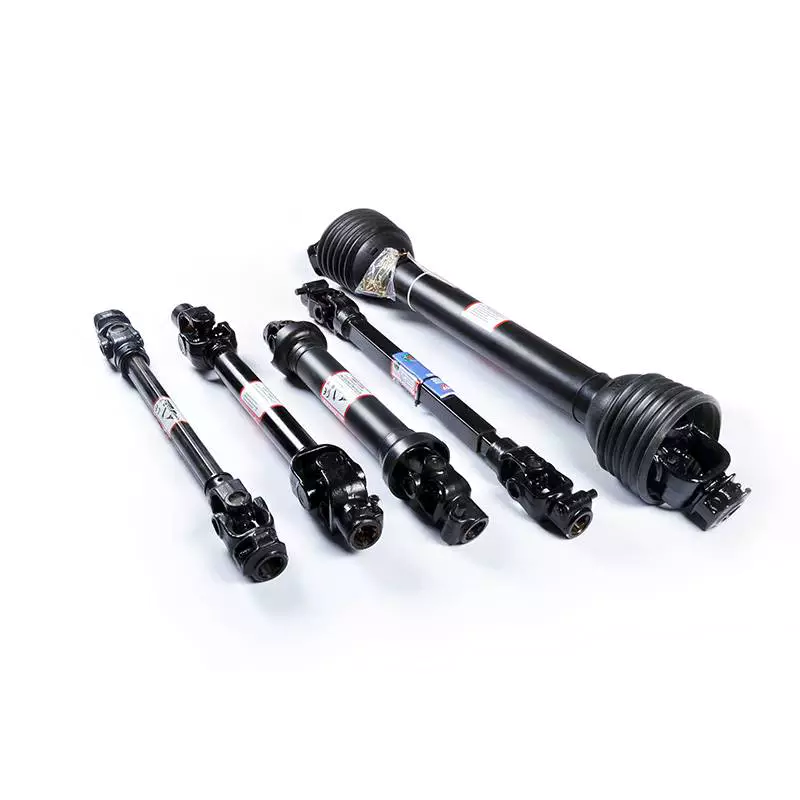
Related Products
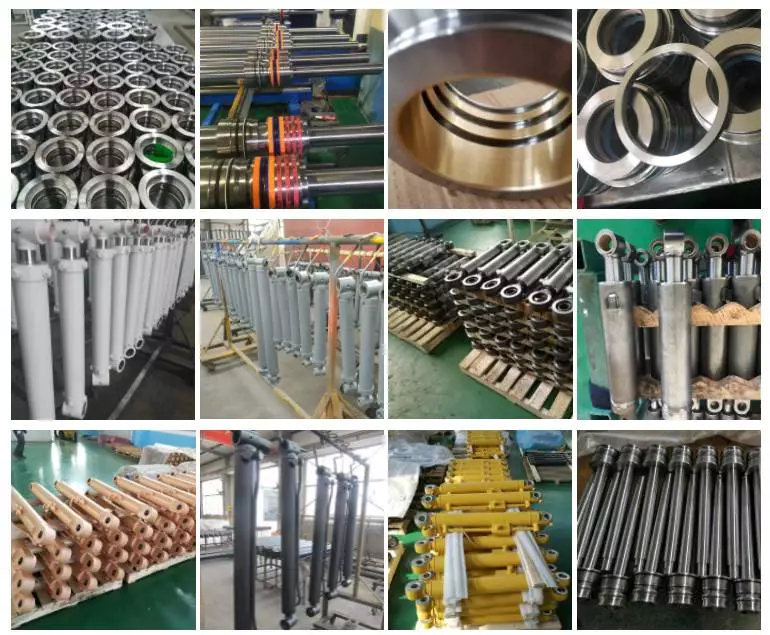
Factory
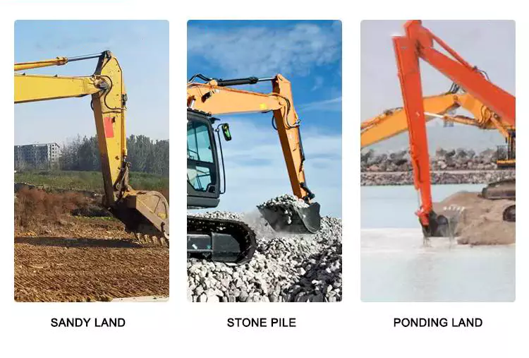
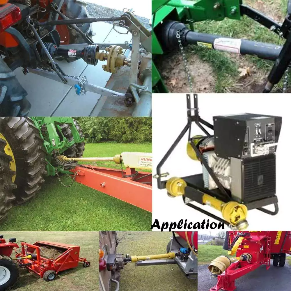
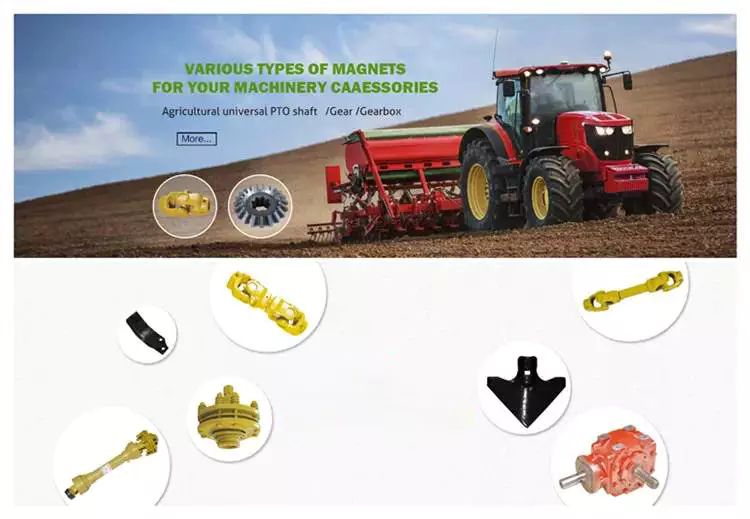
Extensive use for agricultural machines
Guarantee: High precision, high wear resistance, low noise, smooth and steady, high strength
Our factory
| Type: | Agricultural Gearbox |
|---|---|
| Usage: | Agricultural Products Processing, Farmland Infrastructure, Tillage, Harvester, Planting and Fertilization, Grain Threshing, Cleaning and Drying, Agricultural Machine |
| Material: | Carbon Steel |
| Power Source: | Electricity |
| Weight: | OEM |
| After-sales Service: | Installation Guide |
| Samples: |
US$ 999/Piece
1 Piece(Min.Order) | |
|---|
Compatibility with Different Types of Irrigation Pumps
Irrigation gearboxes are designed to be versatile and compatible with various types of irrigation pumps. They can be used with:
- Centrifugal Pumps: These are commonly used for irrigation due to their efficiency and simplicity. Irrigation gearboxes can easily connect to the output shaft of centrifugal pumps, allowing them to convert rotational power to the desired movement for irrigation systems.
- Positive Displacement Pumps: These pumps provide a consistent flow rate and are often used for more precise irrigation applications. Irrigation gearboxes can be integrated to ensure precise control over the movement and speed of positive displacement pumps.
- Submersible Pumps: These pumps are often used in deep wells or reservoirs. While not directly connected to irrigation gearboxes, the gearbox can control the mechanisms that adjust the position of submersible pumps in wells or reservoirs, optimizing water intake.
- Diaphragm Pumps: Diaphragm pumps are commonly used for small-scale irrigation or drip systems. Irrigation gearboxes can regulate the movement of diaphragm pumps, controlling the amount of water released.
The adaptability of irrigation gearboxes makes them suitable for various irrigation pump types, allowing farmers and agricultural operators to efficiently manage water distribution and optimize irrigation practices.
Adaptability of Irrigation Gearboxes for Small and Large-Scale Farming
Irrigation gearboxes are designed with adaptability in mind, making them suitable for both small and large-scale farming:
- Modular Design: Many irrigation gearboxes have a modular design that allows for customization and scalability. Different gearbox sizes and configurations can be selected based on the scale of the farming operation.
- Multiple Ratios: Irrigation gearboxes often come with a range of gear ratios. This allows farmers to choose the appropriate gear ratio for their specific application, whether it's a small-scale garden or a large agricultural field.
- Compatibility: Manufacturers often provide a variety of mounting options and input/output configurations, making it easier to integrate irrigation gearboxes into different irrigation systems, regardless of scale.
- Efficiency and Precision: Regardless of scale, irrigation gearboxes provide efficient water distribution and precise control. This benefits both small gardens and large fields, ensuring water is distributed accurately to the plants' needs.
- Range of Applications: Irrigation gearboxes can be used for various irrigation methods, such as center pivot, linear, and drip irrigation. This versatility makes them suitable for different farming scales.
- Cost-Effectiveness: Manufacturers often offer a range of irrigation gearboxes with varying features and performance levels. Farmers can choose the gearbox that best meets their needs and budget.
- Ease of Maintenance: Many irrigation gearboxes are designed for easy maintenance, which is beneficial regardless of the farming scale. Simple maintenance procedures contribute to the longevity and reliability of the gearboxes.
Overall, the adaptability of irrigation gearboxes makes them a versatile solution for both small and large-scale farming operations, ensuring efficient and controlled water distribution to optimize crop growth.
Industries and Applications Utilizing Irrigation Gearboxes
Irrigation gearboxes find widespread use in various industries and applications where efficient water distribution is essential. Some of the common sectors and scenarios include:
- Agriculture: Irrigation gearboxes are extensively used in agriculture for crop irrigation. They help ensure proper water coverage, reduce water wastage, and improve overall crop yield.
- Horticulture: Nurseries, greenhouses, and orchards rely on irrigation gearboxes to provide controlled water distribution to plants, ensuring optimal growth conditions.
- Turf Management: Sports fields, golf courses, and landscaping areas use irrigation gearboxes to maintain healthy and lush turf by delivering water precisely where needed.
- Land Reclamation: In arid regions or areas affected by drought, irrigation gearboxes are employed for land reclamation projects to establish vegetation and restore ecosystems.
- Municipal Landscaping: Public parks, gardens, and urban landscaping projects utilize irrigation gearboxes to maintain attractive green spaces.
- Mining and Reclamation: Mining sites often require reclamation efforts, and irrigation gearboxes can assist in restoring vegetation in these areas.
These industries and applications benefit from the precise water distribution facilitated by irrigation gearboxes, leading to more efficient water usage, improved plant health, and sustainable land management.
editor by CX 2023-09-23
China manufacturer Customized Axle CNC Hydraulic Pump Motor DC Shaft/Pto Shaft
Product Description
Our advantage:
*Specialization in CNC formulations of high precision and quality
*Independent quality control department
*Control plan and process flow sheet for each batch
*Quality control in all whole production
*Meeting demands even for very small quantities or single units
*Short delivery times
*Online orders and production progress monitoring
*Excellent price-quality ratio
*Absolute confidentiality
*Various materials (stainless steel, iron, brass, aluminum, titanium, special steels, industrial plastics)
*Manufacturing of complex components of 1 - 1000mm.
Production machine:
Inspection equipment :
Certificate:
| Material: | Carbon Steel |
|---|---|
| Load: | Drive Shaft |
| Stiffness & Flexibility: | Stiffness / Rigid Axle |
| Journal Diameter Dimensional Accuracy: | IT01-IT5 |
| Axis Shape: | Straight Shaft |
| Shaft Shape: | Real Axis |
| Customization: |
Available
| Customized Request |
|---|
Can you provide real-world examples of farming machinery that rely on tractor PTO shafts?
Tractor power take-off (PTO) shafts are used to power a wide range of farming machinery and implements. They provide a versatile and efficient method of transmitting power from the tractor to various agricultural equipment. Here are some real-world examples of farming machinery that rely on tractor PTO shafts:
1. Rotary Mowers: Rotary mowers, commonly used for cutting grass, weeds, and vegetation, often rely on PTO shafts for power. The PTO shaft connects the mower to the tractor, enabling the blades to rotate and perform the cutting action.
2. Balers: Balers are used to compress and bale hay, straw, or other forage crops into compact bundles for storage or transportation. PTO-driven balers use the tractor's PTO shaft to power the baling mechanism, which includes the pickup, feeding system, and bale formation components.
3. Hay Rakes: Hay rakes are used to gather and arrange hay into windrows or rows for drying. PTO-driven hay rakes utilize the tractor's PTO shaft to power the rake's rotating tines, which lift and arrange the hay into neat rows.
4. Silage Choppers: Silage choppers are used to chop and process silage, which is fermented and stored animal feed. PTO-driven silage choppers rely on the tractor's PTO shaft to power the cutting mechanism, typically consisting of rotating blades or knives.
5. Seeders and Planters: Seeders and planters are used to sow seeds and plant crops in prepared soil. PTO-driven seeders and planters utilize the tractor's PTO shaft to power the seed metering and distribution mechanism, ensuring accurate seed placement and spacing.
6. Fertilizer Spreaders: Fertilizer spreaders are used to evenly distribute fertilizers, lime, or other soil amendments across fields. PTO-driven fertilizer spreaders rely on the tractor's PTO shaft to power the spreading mechanism, which may include spinning disks or augers.
7. Manure Spreaders: Manure spreaders are used to evenly distribute animal manure or compost onto fields as organic fertilizer. PTO-driven manure spreaders use the tractor's PTO shaft to power the mechanisms that agitate and spread the manure during application.
8. Post Hole Diggers: Post hole diggers are used to dig holes for fence posts, tree planting, or other applications. PTO-driven post hole diggers rely on the tractor's PTO shaft to power the auger that drills into the ground and removes soil.
9. Rotary Tillers: Rotary tillers, also known as rotavators or cultivators, are used to prepare the soil for planting by breaking up and mixing the soil. PTO-driven rotary tillers use the tractor's PTO shaft to power the rotating tines or blades that till the soil.
10. Hay Tedders: Hay tedders are used to spread and aerate hay for faster drying. PTO-driven hay tedders rely on the tractor's PTO shaft to power the rotating tines or paddles that lift and spread the hay.
These are just a few examples of farming machinery that rely on tractor PTO shafts. PTO-driven equipment is widely used in agriculture to enhance efficiency, productivity, and versatility in various farming operations.
How do tractor PTO shafts accommodate variations in length and attachment methods?
Tractor PTO shafts are designed to accommodate variations in length and attachment methods to ensure compatibility with different agricultural implements. Here's a detailed explanation:
1. Telescoping Design: Many tractor PTO shafts feature a telescoping design, allowing them to be adjusted to different lengths. Telescoping PTO shafts have multiple sections that can slide in and out, enabling the shaft to be extended or retracted as needed. This feature helps accommodate variations in the distance between the tractor's PTO output shaft and the implement's input shaft.
2. Adjustable Locking Mechanisms: PTO shafts typically incorporate adjustable locking mechanisms to secure the desired length. These mechanisms may involve pins, clamps, or other locking devices that allow the operator to fix the telescoping sections at the desired position. By adjusting the locking mechanism, the PTO shaft can be set to the appropriate length based on the specific requirements of the equipment.
3. Compatible Attachment Methods: Tractor PTO shafts are designed to accommodate different attachment methods used by agricultural implements. The most common attachment method is the use of a splined connection, where the PTO shaft slides onto the implement's input shaft and is secured with a shear pin or a locking collar. The splined connection allows for a secure and reliable attachment, ensuring efficient power transfer.
4. Adapters and Couplings: In cases where the attachment methods between the tractor and the implement do not match, adapters or couplings can be used. These devices provide compatibility between different attachment methods or spline sizes. Adapters and couplings may feature different types of connections on each end to bridge the gap between the tractor's PTO shaft and the implement's input shaft, allowing for a proper and secure attachment.
5. PTO Shielding: PTO shafts also accommodate variations in PTO shielding requirements. Depending on the implement and local safety regulations, different types of shielding may be necessary. Tractor PTO shafts can be designed with detachable shielding options or offer flexibility in the positioning of safety shields to ensure compliance with safety standards.
By incorporating telescoping designs, adjustable locking mechanisms, compatible attachment methods, adapters and couplings, and considerations for PTO shielding, tractor PTO shafts can accommodate variations in length and attachment methods. These features allow for flexibility and ensure the proper fit and safe operation of the PTO shaft with various agricultural implements.
What Benefits Do Tractor PTO Shafts Offer for Various Agricultural Tasks?
Tractor power take-off (PTO) shafts offer numerous benefits for various agricultural tasks. They provide a versatile and efficient means of powering different implements used in farming operations. Here's a detailed explanation of the benefits that tractor PTO shafts offer for various agricultural tasks:
1. Versatility:
One of the key benefits of tractor PTO shafts is their versatility. PTO shafts allow farmers to connect a wide range of implements to their tractors, including rotary mowers, tillers, balers, spreaders, and more. This versatility enables farmers to perform different tasks with a single tractor, eliminating the need for multiple specialized machines. Farmers can easily switch between implements, adapting to various agricultural activities and increasing operational efficiency.
2. Increased Efficiency:
Tractor PTO shafts significantly enhance efficiency in agricultural tasks. By utilizing a single power source (the tractor's engine) to drive multiple implements, farmers can streamline their operations and save time. Instead of manually operating separate machines, farmers can leverage the power and speed control offered by the tractor's PTO shaft to efficiently perform tasks such as mowing, tilling, planting, harvesting, and more. This increased efficiency allows farmers to accomplish more work in less time, leading to improved productivity.
3. Cost Savings:
The use of tractor PTO shafts can result in cost savings for farmers. By eliminating the need for dedicated engines on each implement, farmers can avoid the expense of purchasing and maintaining multiple machines. Additionally, the versatility of PTO shafts allows farmers to invest in a smaller number of implements that can be used for multiple tasks, further reducing costs. The cost savings associated with tractor PTO shafts can contribute to improved profitability and financial sustainability for farmers.
4. Flexibility:
Tractor PTO shafts offer flexibility in agricultural operations. Farmers can easily attach and detach implements as needed, depending on the specific task at hand. This flexibility allows for rapid adaptation to changing field conditions, crop types, or seasonal requirements. Farmers can quickly switch between implements, such as switching from a mower to a seeder or from a tiller to a sprayer. The ability to utilize different implements with a single tractor provides farmers with the flexibility to optimize their operations and respond to varying agricultural demands.
5. Precise Power Control:
Tractor PTO shafts provide precise power control, allowing farmers to adjust the rotational speed and torque delivered to the implement. Different agricultural tasks require specific power requirements, and the ability to adjust the PTO speed allows farmers to optimize the performance of attached implements. For instance, certain tasks may require higher rotational speed for efficient cutting or lower speed for precise soil cultivation. The ability to control power output through the PTO shaft contributes to improved accuracy and effectiveness in various agricultural operations.
6. Standardization:
Tractor PTO shafts follow standardized connection interfaces, ensuring compatibility between tractors and implements from different manufacturers. This standardization allows farmers to easily connect implements to their tractors without compatibility issues. Farmers have a wide range of implements to choose from, and the standardized PTO shaft connection ensures seamless integration and operation. Standardization simplifies equipment selection, replacement, and compatibility concerns, enhancing the convenience and effectiveness of agricultural tasks.
7. Safety Considerations:
While not a direct benefit for agricultural tasks, tractor PTO shafts incorporate safety features to protect operators and bystanders. PTO shafts are typically equipped with protective guards or shields that cover the rotating shaft, reducing the risk of accidents or entanglement. These safety features help prevent injuries and promote safe working conditions in agricultural operations.
In summary, tractor PTO shafts offer numerous benefits for various agricultural tasks. They provide versatility, increased efficiency, cost savings, flexibility, precise power control, and standardized compatibility. By leveraging the power of the tractor's engine, PTO shafts enable farmers to efficiently power different implements, enhancing productivity and optimizing farming operations.


editor by CX 2023-09-15
China Hot selling Customized Axle CNC Hydraulic Pump Motor DC Shaft/Pto Shaft
Product Description
Our advantage:
*Specialization in CNC formulations of high precision and quality
*Independent quality control department
*Control plan and process flow sheet for each batch
*Quality control in all whole production
*Meeting demands even for very small quantities or single units
*Short delivery times
*Online orders and production progress monitoring
*Excellent price-quality ratio
*Absolute confidentiality
*Various materials (stainless steel, iron, brass, aluminum, titanium, special steels, industrial plastics)
*Manufacturing of complex components of 1 - 1000mm.
Production machine:
Inspection equipment :
Certificate:
| Material: | Carbon Steel |
|---|---|
| Load: | Drive Shaft |
| Stiffness & Flexibility: | Stiffness / Rigid Axle |
| Journal Diameter Dimensional Accuracy: | IT01-IT5 |
| Axis Shape: | Straight Shaft |
| Shaft Shape: | Real Axis |
| Customization: |
Available
| Customized Request |
|---|

Are there variations in PTO shaft designs for different types of machinery?
Yes, there are variations in PTO (Power Take-Off) shaft designs to accommodate the specific requirements of different types of machinery. PTO shafts are highly versatile and adaptable components used to transfer power from a power source, such as a tractor or engine, to driven machinery or equipment. The design variations in PTO shafts are necessary to ensure compatibility, efficiency, and safety in various applications. Here's a detailed explanation of the different PTO shaft designs for different types of machinery:
1. Standard PTO Shafts: Standard PTO shafts are the most common design and are widely used in a variety of applications. They typically consist of a solid steel shaft with a universal joint at each end. These universal joints allow for angular misalignment between the power source and the driven machinery. Standard PTO shafts are suitable for applications where the distance between the power source and the driven machinery remains relatively fixed. They are commonly used in agricultural implements, such as mowers, balers, tillers, and seeders, as well as in industrial applications.
2. Telescopic PTO Shafts: Telescopic PTO shafts feature a telescoping design that allows for length adjustment. These shafts consist of two or more concentric shafts that can slide within each other. Telescopic PTO shafts are beneficial in applications where the distance between the power source and the driven machinery varies. By adjusting the length of the shaft, operators can ensure proper power transmission without the risk of the shaft dragging on the ground or being too short to reach the equipment. Telescopic PTO shafts are commonly used in front-mounted implements, snow blowers, self-loading wagons, and other applications where the distance between the power source and the implement changes.
3. CV (Constant Velocity) PTO Shafts: CV PTO shafts incorporate Constant Velocity joints to accommodate misalignment and angular variations. These joints maintain a constant speed and torque transfer even when the driven machinery is at an angle relative to the power source. CV PTO shafts are beneficial in applications where the driven machinery requires flexibility and a wide range of movement. They are commonly used in articulated loaders, telescopic handlers, self-propelled sprayers, and other equipment that requires continuous power transmission while operating at various angles.
4. Gearbox Driven PTO Shafts: Some machinery requires specific speed or torque ratios between the power source and the driven equipment. In such cases, PTO shafts may incorporate gearbox systems. Gearbox driven PTO shafts allow for speed reduction or increase and can change the rotational direction if necessary. The gear ratios in the gearbox can be adjusted to match the speed and torque requirements of the driven machinery. These PTO shafts are commonly used in applications where the power source operates at a different speed or torque level than the equipment it drives, such as in certain industrial manufacturing processes and specialized machinery.
5. High-Torque PTO Shafts: Some heavy-duty machinery requires high torque levels for power transmission. High-torque PTO shafts are designed to handle these demanding applications. They are constructed with reinforced components, including larger diameter shafts and heavier-duty universal joints, to withstand the increased torque requirements. High-torque PTO shafts are commonly used in equipment such as wood chippers, crushers, and heavy-duty agricultural implements that require substantial power and torque for their operation.
6. Safety PTO Shafts: Safety is a crucial consideration when using PTO shafts. Safety PTO shafts incorporate mechanisms to reduce the risk of accidents and injuries. One common safety feature is the use of protective guards that cover the rotating shaft to prevent accidental contact. These guards are typically made of metal or plastic and are designed to shield the rotating components while allowing the necessary movement for power transmission. Safety PTO shafts are used in various applications where the risk of entanglement or accidental contact with the rotating shaft is high, such as in grass mowers, rotary cutters, and other equipment used in landscaping and agriculture.
These are some of the key variations in PTO shaft designs for different types of machinery. The specific design used depends on factors such as the application requirements, power source characteristics, torque levels, movement flexibility, and safety considerations. PTO shaft manufacturers offer a range of designs to ensure compatibility and efficient power transmission in diverse industries and applications.

What safety precautions should be followed when working with PTO shafts?
Working with Power Take-Off (PTO) shafts requires strict adherence to safety precautions to prevent accidents and ensure the well-being of individuals operating or working in the vicinity of the equipment. PTO shafts involve rotating machinery and can pose significant hazards if not handled properly. Here are several important safety precautions that should be followed when working with PTO shafts:
1. Familiarize Yourself with the Equipment: Prior to operating or working near a PTO shaft, it is crucial to thoroughly understand the equipment's operation, including the specific PTO shaft configuration, safety features, and any associated machinery. Read and follow the manufacturer's instructions and safety guidelines pertaining to the PTO shaft and associated equipment. Training and familiarity with the equipment are essential to ensure safe practices.
2. Wear Appropriate Personal Protective Equipment (PPE): When working with PTO shafts, individuals should wear appropriate personal protective equipment to minimize the risk of injury. This may include safety glasses, hearing protection, gloves, and sturdy footwear. PPE protects against potential hazards such as flying debris, noise, and accidental contact with rotating components.
3. Guarding and Shielding: Ensure that the PTO shaft and associated machinery are equipped with appropriate guarding and shielding. Guarding helps prevent accidental contact with rotating parts, reducing the risk of entanglement or injury. PTO shafts should have guard shields covering the rotating shaft and any exposed universal joints. Machinery driven by the PTO shaft should also have adequate guarding in place to protect against contact with moving parts.
4. Securely Fasten and Align PTO Shaft Components: Before operating or connecting the PTO shaft, ensure that all components are securely fastened and aligned. Loose or misaligned components can lead to shaft dislodgement, imbalance, and potential failure. Follow the manufacturer's guidelines for proper installation and tightening of couplings, yokes, and other connecting points. Proper alignment is crucial to prevent excessive stress, vibrations, and premature wear on the PTO shaft and associated equipment.
5. Avoid Loose Clothing and Jewelry: Loose clothing, jewelry, or other items that can become entangled in the PTO shaft or associated machinery should be avoided. Secure long hair, tuck in loose clothing, and remove or properly secure any dangling accessories. Loose items can get caught in rotating parts, leading to serious injury or entanglement hazards.
6. Do Not Modify or Remove Safety Features: PTO shafts are equipped with safety features such as guard shields, safety covers, and torque limiters for a reason. These features are designed to protect against potential hazards and should not be modified, bypassed, or removed. Altering or disabling safety features can significantly increase the risk of accidents and injury. If any safety features are damaged or not functioning correctly, they should be repaired or replaced promptly.
7. Shut Down Power Source Before Maintenance: Before performing any maintenance, repairs, or adjustments on the PTO shaft or associated machinery, ensure that the power source is completely shut down and disconnected. This includes turning off the engine, disconnecting power supply, and engaging any safety locks or mechanisms. Lockout/tagout procedures should be followed to prevent accidental energization or startup during maintenance activities.
8. Regular Maintenance and Inspection: Regular maintenance and inspection of the PTO shaft and associated equipment are vital for safe operation. Follow the manufacturer's recommended maintenance schedule and perform routine inspections to identify any signs of wear, damage, or misalignment. Lubricate universal joints as per the manufacturer's guidelines to ensure smooth operation. Promptly address any maintenance or repair needs to prevent potential hazards.
9. Training and Communication: Ensure that individuals operating or working near PTO shafts receive proper training on safe work practices, hazard identification, and emergency procedures. Promote clear communication regarding the presence and operation of PTO shafts to prevent accidental contact or interference. Establish effective communication methods, such as signals or radios, when working in teams or near noisy equipment.
10. Be Aware of Surroundings: Maintain situational awareness when working with PTO shafts. Be mindful of the location of bystanders, obstacles, and potential hazards. Ensure a clear and safe work area around the PTO shaft. Avoid distractions and focus on the task at hand to prevent accidents caused by inattention.
By following these safety precautions, individuals can minimize the risk of accidents and injuries when working with PTO shafts. Safety should always be the top priority to ensure a safe and productive work environment.

What is a PTO shaft and how is it used in agricultural and industrial equipment?
A power take-off (PTO) shaft is a mechanical component used in agricultural and industrial equipment to transfer power from a power source, such as an engine or motor, to another machine or implement. It is a driveline shaft that transmits rotational power and torque, allowing the connected equipment to perform various tasks. PTO shafts are commonly used in agricultural machinery, such as tractors, as well as in industrial equipment, including generators, pumps, and construction machinery. Here's a detailed explanation of what a PTO shaft is and how it is used:
Structure and Components: A typical PTO shaft consists of a hollow metal tube with universal joints at each end. The hollow tube allows the shaft to rotate freely, while the universal joints accommodate angular misalignments between the power source and the driven equipment. The universal joints consist of a cross-shaped yoke with needle bearings, providing flexibility and allowing the transmission of power at varying angles. Some PTO shafts may also include a telescopic section to adjust the length for different equipment setups or to accommodate varying distances between the power source and the driven machine.
Power Transfer: The primary function of a PTO shaft is to transfer power and torque from the power source to the driven equipment. The power source, typically an engine or motor, drives the PTO shaft through a mechanical connection, such as a gearbox or a clutch. As the power source rotates, it transmits rotational force to the PTO shaft. The PTO shaft, in turn, transfers this rotational power and torque to the driven equipment, enabling it to perform its intended function. The torque and rotational speed transmitted through the PTO shaft depend on the power source's characteristics and the gear ratio or clutch engagement.
Agricultural Applications: In agriculture, PTO shafts are commonly used in tractors to power various implements and attachments. The PTO shaft is connected to the tractor's power take-off, a rotating drive shaft located at the rear of the tractor. By engaging the PTO clutch, the tractor's engine power is transferred through the PTO shaft to the attached implements. Agricultural machinery, such as mowers, balers, tillers, sprayers, and grain augers, often rely on PTO shafts to receive power for their operation. The PTO shaft allows the implements to be powered directly by the tractor's engine, eliminating the need for separate power sources and increasing the versatility and efficiency of agricultural operations.
Industrial Applications: PTO shafts also find extensive use in various industrial applications. Industrial equipment, such as generators, pumps, compressors, and industrial mixers, often incorporate PTO shafts to receive power from engines or electric motors. The PTO shaft connects the power source to the driven equipment, allowing it to operate and perform its intended function. In construction machinery, PTO shafts can be found in equipment like concrete mixers, hydraulic hammers, and post hole diggers, enabling the transfer of power from the machinery's engine to the specific attachment or tool being used.
Safety Considerations: It is important to note that PTO shafts can pose safety risks if not handled properly. The rotating shaft can cause serious injuries if operators come into contact with it while it is in operation. To ensure safety, PTO shafts are often equipped with shielding or guards that cover the rotating shaft and universal joints, preventing accidental contact. It is crucial to maintain and inspect these safety features regularly to ensure their effectiveness. Additionally, operators should receive proper training on PTO shaft operation, including safe attachment and detachment procedures, as well as the use of personal protective equipment when working near PTO-driven machinery.
In summary, a PTO shaft is a mechanical component used in agricultural and industrial equipment to transmit power and torque from a power source to a driven machine or implement. It enables the direct power transfer from engines or motors to various equipment, increasing efficiency and versatility in agricultural and industrial operations. While PTO shafts offer significant benefits, operators must be aware of the associated safety considerations and take appropriate precautions to prevent accidents and injuries.
editor by CX 2023-09-14
China 180w motor power two pump head miniature high portable vaccum pump with gauge
Classification: Other
Customized support: OEM
Model Number: LH-85DL
Application: Vacuum Filtration
Function: Vacuum&Pressute
Weight: 10kg
Size(mm): 40*24*34
Motor Power: 180W
Pump head: 2
Product name: Oil less Diaphragm Vacuum Pump
MOQ: 1
Pressure: 40Psi
Packaging Details: Shock-proof Carton Package1 Set/Carton
Port: ZheZheJiang ngang Port, China
Detailed Images Oil Less Diaphragm Vacuum Pump—-LH-85DL Diaphragm Vacuum PumpLH series of diaphragm vacuum pump is our patent protected product. This kind of pump can run continuously without oil, and with low noise and high efficiency. They have different applications, such as vacuum filtration, for Rotary Evaporator, and 2 functional pump (both vacuum and pressure) which will save your lab purchasing cost. Manifolds Vacuum FiltrationManifolds Vacuum Filtration is used primarily in microbiological and analytical procedures that involve collecting a particulate (bacteria, precipitate, etc.) from a liquid suspension. They are particular designed and produced for several samples filtrate at the same time. Because each filter holder has individial control valve, only 1 set vacuum pump can sustain the single or Multi-branch manifold filter operate together. Products Description Technical Data of Diaphragm Vacuum Pump
| Model | LH-85(/C) | LH-85L(/C) | LH-95D(/C) | LH-85DL(/C) |
| Pumping Speed (L/min) | 30 | 30 | 30 | 60 |
| Ultimate Vacuum(Mbar) | >0.085(150mbar) | >0.085(150mbar) | >0.095(50mbar) | >0.085(150mbar) |
| Pressure(Psi) | — | 40 | — | 40 |
| Pump Head | 1 | 1 | 2 | 2 |
| Motor Power(w) | 180 | 180 | 180 | 180 |
| Size(L×W×H)(mm) | 250×135×210 | 250×135×210 | 315×135×210 | 315×135×210 |
| Weight | 7.5 | 8 | 10 | 10 |
| Noise(dB) | <50 | <50 | < 25 AEL-31927 we can produce by your samples or technical drawings. We can build the molds and fixtures.Q5. What is your sample policy?A: We can supply the sample if we have ready parts in stock, but the customers have to pay the sample cost and the courier cost.Q6. Do you test all your goods before delivery?A: Yes, we have 100% test before delivery
What Are Vacuum Pumps?Vacuum pumps use air flow as the source of energy. The system is ideal for dewatering wet media, creating filter cakes, and pneumatically moving materials through a pipe. A vacuum pump works through air flow that is moved by differential pressure. The pump's air flow develops a vacuum in a chamber that is called the vacuum box. As the air flow collects gas at a faster rate than atmospheric pressure, it is considered the "heart" of a vacuum system. Principles of operationVacuum pumps work by reducing the volume of air that moves through them. Depending on the design, there are several different types of vacuum pumps. All of these types operate under the same principles, but have their own special features. Here are some of their most important characteristics. In addition to their capacity, the main differences between these pumps are their manufacturing tolerances, materials of construction, and level of tolerance for chemicals, oil vapor, and vibration. DesignA vacuum pump is a mechanical device used to generate a vacuum. It can create a low or high vacuum. These pumps are used in the process of oil regeneration and re-refining. The design of a vacuum pump must be compatible with the vacuum. The pump's mass and speed should be matched. PerformanceThe performance of a vacuum pump is an important indicator of its overall condition. It helps determine whether the system is performing optimally and how high the ultimate vacuum level can be achieved. A performance log should be maintained to document variations in pump operating hours and voltage as well as the temperature of the pump's cooling water and oil. The log should also record any problems with the pump. Atmospheric pressureVacuum pumps work by sucking liquids or air into a container. The amount of vacuum a pump can create is measured in pressure units called atms (atmospheric pressure). The pressure of a vacuum pump is equal to the difference between atmospheric pressure and the pressure in the system. Typical applicationVacuum pumps are used in a variety of applications. They generate low and high pressures and are used to evaporate water or gases from various materials. They are also used in petroleum regeneration and re-refining processes. Typical applications of vacuum pumps include: a.
|