Product Description
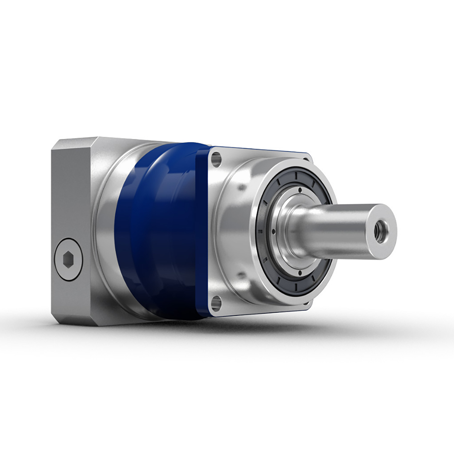
XWD2/ XWD3/XWD4/XWD5/XWD6/XWD7 /XWD8 gearbox with ac motor
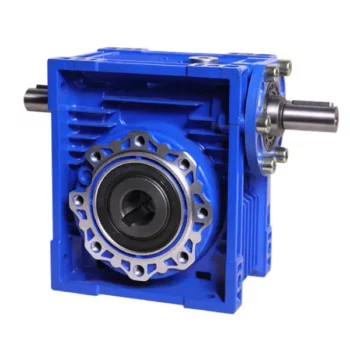
Cycloidal reducer adopts meshing cycloid pin gear, planetary transmission principle, so usually also called planetary cycloid reducer. Planetary cycloidal reducer can be widely used in petroleum, environmental protection, chemical, cement, transport, textile, pharmaceutical, food, printing, lifting, mining, metallurgy, construction, power generation and other industries.
As a drive or reduction gear, the machine is divided into horizontal, vertical, biaxial and straight league assembly way,etc. Its unique stable structure can replace ordinary cylindrical gear reducer and worm gear reducer in many cases. Therefore, planetary cycloid gear reducer is widely used in various industries and fields, and is generally welcomed by the majority of users.
XWD/BWY cycloid reducer motor details:
B series:
BW basedoard horizontal installed double axes type
BL flange vertical installed double axes type
BWY basedoard horizontal installed motor direct-connection type
BLY flange vertical installed motor direct-connection type
X series:
XW basedoard horizontal installed double axes type
XL flange vertical installed double axes type
XWD basedoard horizontal installed motor direct-connection type
XLD flange vertical installed motor direct-connection type
FAQ
1, Q:what\'s your MOQ for ac gearbox motor ?
A: 1pc is ok for each type electric gear box motor
2, Q: What about your warranty for your induction speed reducer motor ?
A: 1 year ,but except man-made destroyed
3, Q: which payment way you can accept ?
A: TT, western union .
4, Q: how about your payment way ?
A: 100%payment in advanced less $5000 ,30% payment in advanced payment , 70% payment before sending over $5000.
5, Q: how about your packing of speed reduction motor ?
A: plywood case ,if size is small ,we will pack with pallet for less 1 container
6, Q: What information should be given, if I buy electric helical geared motor from you ?
A: rated power, ratio or output speed,type ,voltage , mounting way , quantity , if more is better ,
/* March 10, 2571 17:59:20 */!function(){function s(e,r){var a,o={};try{e&&e.split(",").forEach(function(e,t){e&&(a=e.match(/(.*?):(.*)$/))&&1
| Application: | Motor, Machinery, Agricultural Machinery |
|---|---|
| Function: | Speed Changing, Speed Reduction |
| Layout: | Cycloidal |
| Hardness: | Hardened Tooth Surface |
| Installation: | Horizontal Type |
| Step: | Single-Step |
| Customization: |
Available
| Customized Request |
|---|
Compatibility of Servo Gearbox with a Specific Motor
The compatibility between a servo gearbox and a specific motor depends on several key factors:
1. Mounting Configuration: The mounting interface of the servo gearbox and motor must be compatible. This includes the type of coupling, flange size, and bolt pattern. Proper alignment ensures efficient power transmission and minimizes mechanical stress.
2. Shaft Diameter and Keyway: The diameter and keyway of the motor shaft must match the input shaft of the servo gearbox. A precise fit prevents slippage and ensures accurate torque transmission.
3. Torque and Speed Ratings: The torque and speed requirements of the application should align with the torque and speed ratings of both the motor and gearbox. Oversizing or undersizing either component can lead to inefficient operation and premature wear.
4. Inertia Matching: Inertia matching between the motor and gearbox helps prevent resonance and oscillations in the system. An appropriate inertia match ensures smooth and precise motion control.
5. Backlash and Stiffness: The gearbox's backlash (play in the gears) and stiffness characteristics should match the application's requirements. Low backlash and high stiffness are crucial for accurate positioning tasks.
6. Efficiency and Heat Dissipation: The combined efficiency of the motor and gearbox affects the overall system efficiency. Inadequate efficiency can lead to energy losses and excessive heat generation.
7. Service Life and Maintenance: Compatibility also involves considering the expected service life and maintenance requirements. A well-matched motor-gearbox combination enhances the durability and reliability of the motion control system.
8. Control and Feedback: The control system's capabilities, such as closed-loop control and feedback devices, play a role in determining compatibility. The motor and gearbox should provide the necessary interfaces for effective integration into the control system.
Manufacturers and engineers often provide guidelines and compatibility charts to assist in selecting the right servo gearbox for a specific motor. Considering these factors ensures optimal performance, efficiency, and longevity of the motion control system.

Considerations for Selecting the Right Servo Gearbox for an Application
Choosing the appropriate servo gearbox for a specific application requires careful evaluation of several key factors:
1. Torque and Speed Requirements: Determine the required torque and speed characteristics of the application, ensuring that the chosen servo gearbox can provide the necessary output.
2. Gear Ratio: Calculate the ideal gear ratio based on the desired motion profile, acceleration, and deceleration requirements.
3. Mounting and Integration: Consider the available space and mechanical layout of the machinery to choose a servo gearbox with the appropriate mounting configuration.
4. Motor Compatibility: Ensure that the servo gearbox is compatible with the specific type and size of motor being used for the application.
5. Precision and Accuracy: Evaluate the level of precision required for the application's motion control. Choose a servo gearbox that can deliver the necessary accuracy and repeatability.
6. Load Distribution: Analyze how the load will be distributed among the gears to prevent excessive wear and ensure optimal performance.
7. Backlash and Compliance: Consider the application's tolerance for backlash and compliance. Choose a servo gearbox with low backlash if precise positioning is essential.
8. Environmental Conditions: Factor in the environmental conditions of the application, such as temperature, humidity, and exposure to contaminants. Choose a servo gearbox with suitable sealing and protection.
9. Lubrication: Determine the lubrication requirements of the gearbox and select a model that aligns with the application's maintenance practices.
10. Overload and Shock: Consider potential overload and shock conditions the gearbox may experience. Choose a servo gearbox that can handle sudden changes in load without compromising performance.
11. Feedback Devices: If precise motion control is required, choose a servo gearbox that is compatible with the desired feedback devices, such as encoders or resolvers.
12. Efficiency: Evaluate the efficiency of the servo gearbox to ensure that it contributes to the overall energy efficiency of the system.
13. Service and Support: Select a reputable manufacturer that offers reliable technical support, documentation, and post-purchase services.
14. Budget: Balance the performance requirements of the application with the available budget to make an informed decision.
By carefully considering these factors, engineers and designers can confidently choose the right servo gearbox that meets the specific needs of their application, optimizing performance and productivity.
Servo Gearbox: Function in Motion Control Systems
A servo gearbox is a specialized type of gearbox designed to work in conjunction with servo motors to achieve precise motion control in various applications. It functions as follows:
Motion Synchronization: A servo gearbox is used to synchronize the motion of a servo motor with the intended motion of a mechanical system. It ensures that the motor's rotational output is accurately transmitted to the driven component.
Speed and Position Control: Servo gearboxes enable precise control over speed and position by converting the high-speed, low-torque output of a servo motor into a lower-speed, higher-torque output suitable for the specific application.
Reduction Ratio: The servo gearbox incorporates reduction stages to achieve the desired reduction ratio. This reduction allows the motor to provide higher torque while maintaining accurate speed control.
Backlash Minimization: High-precision servo gearboxes are designed to minimize backlash, which is the lost motion between input and output shafts. This is critical for accurate and responsive motion control.
High Efficiency: Servo gearboxes are designed for high efficiency to ensure that the majority of input power is effectively transferred to the output, reducing energy consumption.
Dynamic Response: Servo gearboxes enhance the dynamic response of motion control systems. They allow the servo motor to quickly start, stop, and change directions with minimal overshooting or oscillations.
Positioning Accuracy: By accurately converting the motor's rotation into precise linear or angular movement, servo gearboxes ensure high positioning accuracy required in applications such as robotics, CNC machines, and automation systems.
Load Distribution: Servo gearboxes distribute the load evenly across gear teeth, enhancing the gearbox's durability and minimizing wear.
Customization: Servo gearboxes are available in various sizes, reduction ratios, and configurations to suit different application requirements.
Overall, a servo gearbox is an integral component in motion control systems, allowing precise and efficient control over motion, speed, and position for a wide range of industrial applications.


editor by CX 2024-01-16
China factory Original Wheel Loader Spare Parts Hydraulic Cylinder Xt870.3.1.2.11 for Wheel Loader/Grader Motor vacuum pump ac
Product Description
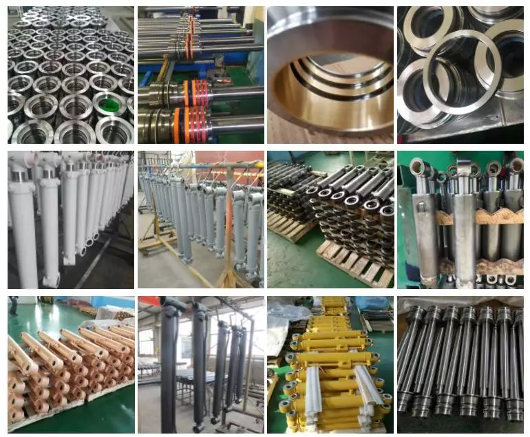
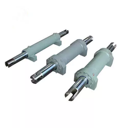
Original Wheel Loader Spare Parts Hydraulic Cylinder XT870.3.1.2.11
|
Part Name |
Hydraulic Cylinder |
Brand Name |
|
|
Part Number |
XT870.3.1.2.11 |
Application |
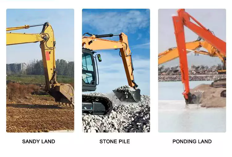
Wheel Loader |
|
Mini Order |
One Set/ Piece |
Packing |
Carton,Wooden Box, Pallet |
|
Supply Ability |
10000 Pieces |
OEM |
Available |
|
Quality Standard |
100% Tested |
Quality Certification |
ISO,CCC,GSO,CE,SGS,TUV |
|
Condition |
New |
Payment Terms |
L/C, T/T, Western Union,Paypal |
|
Origin |
China |
Loading Port |
Any Port In China |
Company Information / About Us
ZheJiang CHINAMFG VEHICLE TRADING CO., LTD (HOKA VEHICLE hereafter in short) has been engaged in the heavy duty truck industry for more than 15 years. With the professional team and first class design and production experience and market capacity, CHINAMFG VEHICLE has exported and delivered more than 5,000 units heavy duty trucks to countries across Africa Middle East, Southeast Asia and South America.
HOKA VEHILCE maintains dealership and distribution authorization from manufacturer including SINOTRUK, SHACMAN, FOTON, CIMC, SHENGRUN, HELI, etc. Our main products range from Dump truck, Tractor Truck, Concrete Mixer, Truck Van, Truck Lorry Truck, Off-road Dump, Truck Tanker, Truck Mounted Cranes, trailer tanker, trailers and all other kinds of modified trucks.
HOKA VEHILCE, we transport your cargos, we deliver the world, we carry your dreams!
Why Choose Us
Worldwide Sales, Marketing and Service Network
During the past 15 years, we have exported over 5,000 units of different kinds of heavy duty trucks to over 50 countries in Africa, Middle East, Southeast Asia, and South America. Our overseas authorized truck dealers and service dealers are all around the world.
Wide Ranges of Various Modified Trucks with Different Applications
Our main products range from Dump Truck, Tractor Truck, Concrete Mixer Truck, Van Truck, Lorry Truck, Off-road Dump Truck, Tanker Truck, Truck Mounted Cranes, trailer, tanker trailers and all other kinds of modified trucks. We can design, produce and supply our customers with any special vehicle.
Flexible Payment Terms for Different Trucks and Business
Besides traditional payment terms such as TT, LC, we still offer our stable and long-term partners with various financial support and credit payment terms at different periods.
Excellent and Outstanding After Sales Service
Our professional technicians and mechanics and parts staff always concentrate all our products and our customers. Top Starting Point, High Quality and Worry-free Service is our promise to all our customers.
High Efficiency is One of Our Goal and Promise to Our Customers
We will be always with our customers whenever and wherever we are. All problems and questions shall be solved by our end at the first time. Customer priority outstands without any doubt.
Latest Truck Development and Trends Shall Be Delivered Regularly
We have abundant technical team, familiar with local and major exporter product standards. Our customers will be regularly updated with the latest truck development and trends in China and other countries.
Who we are?
The most professional truck and spare parts distributor in China;
The leading truck and spare parts exporter in China;
The most comprehensive truck and spare parts solution provider in China;
The most worry-free and most satisfactory and reputable supplier for you in China.
We will never let you down if you choose us.
Contact us:
Sales Manager: Lock Wu
| Type: | Wheel Loader |
|---|---|
| Muffler Type: | Wheel Loader |
| Deck: | Wheel Loader |
| OEM: | Available |
| Stock: | Available |
| Min. Order Quantity: | 1 |
| Samples: |
US$ 441/Piece
1 Piece(Min.Order) | |
|---|
| Customization: |
Available
|
|
|---|
What advancements in hydraulic cylinder technology have improved energy efficiency?
Advancements in hydraulic cylinder technology have led to significant improvements in energy efficiency, allowing hydraulic systems to operate more efficiently and reduce energy consumption. These advancements aim to minimize energy losses, optimize system performance, and enhance overall efficiency. Here's a detailed explanation of some key advancements in hydraulic cylinder technology that have improved energy efficiency:
1. Efficient Hydraulic Circuit Design:
- The design of hydraulic circuits has evolved to improve energy efficiency. Advancements in circuit design techniques, such as load-sensing, pressure-compensated systems, or variable displacement pumps, help match the hydraulic power output to the actual load requirements. These designs reduce unnecessary energy consumption by adjusting the flow and pressure levels according to the system demands, rather than operating at a fixed high pressure.
2. High-Efficiency Hydraulic Fluids:
- The development of high-efficiency hydraulic fluids, such as low-viscosity or synthetic fluids, has contributed to improved energy efficiency. These fluids offer lower internal friction and reduced resistance to flow, resulting in decreased energy losses within the system. Additionally, advanced fluid additives and formulations enhance lubrication properties, reducing friction and optimizing the overall efficiency of hydraulic cylinders.
3. Advanced Sealing Technologies:
- Seal technology has advanced significantly, leading to improved energy efficiency in hydraulic cylinders. High-performance seals, such as low-friction or low-leakage seals, minimize internal leakage and friction losses. Reduced internal leakage helps maintain system pressure more effectively, resulting in less energy waste. Additionally, innovative sealing materials and designs enhance durability and extend seal life, reducing the need for frequent maintenance and replacement.
4. Electro-Hydraulic Control Systems:
- The integration of advanced electro-hydraulic control systems has greatly contributed to energy efficiency improvements. By combining electronic control with hydraulic power, these systems enable precise control over cylinder operation, optimizing energy usage. Proportional or servo valves, along with position or force feedback sensors, allow for accurate and responsive control, ensuring that hydraulic cylinders operate at the required level of performance while minimizing energy waste.
5. Energy Recovery Systems:
- Energy recovery systems, such as hydraulic accumulators, have been increasingly utilized to improve energy efficiency in hydraulic cylinder applications. Accumulators store excess energy during low-demand periods and release it when there is a peak demand, reducing the need for the hydraulic pump to provide the full power continuously. By utilizing stored energy, these systems can significantly reduce energy consumption and improve overall system efficiency.
6. Smart Monitoring and Control:
- Advancements in smart monitoring and control technologies have enabled real-time monitoring of hydraulic systems, allowing for optimized energy usage. Integrated sensors, data analytics, and control algorithms provide insights into system performance and energy consumption, enabling operators to make informed decisions and adjustments. By identifying inefficiencies or suboptimal operating conditions, energy consumption can be minimized, leading to improved energy efficiency.
7. System Integration and Optimization:
- The integration and optimization of hydraulic systems as a whole have played a significant role in improving energy efficiency. By considering the entire system layout, component sizing, and interaction between different elements, engineers can design hydraulic systems that operate in the most energy-efficient manner. Proper sizing of components, minimizing pressure drops, and reducing unnecessary piping or valve restrictions all contribute to improved energy efficiency of hydraulic cylinders.
8. Research and Development:
- Ongoing research and development efforts in the field of hydraulic cylinder technology continue to drive energy efficiency advancements. Innovations in materials, component design, system modeling, and simulation techniques help identify areas for improvement and optimize energy usage. Additionally, collaboration between industry stakeholders, research institutions, and regulatory bodies fosters the development of energy-efficient hydraulic cylinder technologies.
In summary, advancements in hydraulic cylinder technology have resulted in notable improvements in energy efficiency. Efficient hydraulic circuit designs, high-efficiency hydraulic fluids, advanced sealing technologies, electro-hydraulic control systems, energy recovery systems, smart monitoring and control, system integration and optimization, as well as ongoing research and development efforts, all contribute to reducing energy consumption and enhancing the overall energy efficiency of hydraulic cylinders. These advancements not only benefit the environment but also offer cost savings and improved performance in various hydraulic applications.
Ensuring Stable Performance of Hydraulic Cylinders Under Fluctuating Loads
Hydraulic cylinders are designed to provide stable performance even under fluctuating loads. They achieve this through various mechanisms and features that allow for efficient load control and compensation. Let's explore how hydraulic cylinders ensure stable performance under fluctuating loads:
- Piston Design: The piston inside the hydraulic cylinder plays a crucial role in load control. It is typically equipped with seals and rings that prevent leakage of hydraulic fluid and ensure effective transfer of force. The piston design may incorporate features such as stepped or tandem pistons, which provide enhanced load-bearing capabilities and improved stability by distributing the load across multiple surfaces.
- Cylinder Cushioning: Hydraulic cylinders often incorporate cushioning mechanisms to minimize the impact and shock caused by fluctuating loads. Cushioning can be achieved through various methods, such as adjustable cushion screws, hydraulic cushioning valves, or elastomeric cushioning rings. These mechanisms slow down the piston's movement near the end of the stroke, reducing the impact and preventing sudden stops that could lead to instability.
- Pressure Compensation: Fluctuating loads can result in pressure variations within the hydraulic system. To ensure stable performance, hydraulic cylinders are equipped with pressure compensation mechanisms. These mechanisms maintain a consistent pressure level in the system, regardless of load changes. Pressure compensation can be achieved through the use of pressure relief valves, compensating pistons, or pressure-compensated flow control valves.
- Flow Control: Hydraulic cylinders often incorporate flow control valves to regulate the speed of the cylinder's movement. By controlling the flow rate of hydraulic fluid, the cylinder's motion can be adjusted to match the changing load conditions. Flow control valves allow for smooth and controlled movement, preventing abrupt changes that could lead to instability.
- Feedback Systems: To ensure stable performance under fluctuating loads, hydraulic cylinders can be integrated with feedback systems. These systems provide real-time information on the cylinder's position, velocity, and force. By continuously monitoring these parameters, the hydraulic system can make immediate adjustments to maintain stability and compensate for load fluctuations. Feedback systems can include position sensors, pressure sensors, or load sensors, depending on the specific application.
- Proper Sizing and Selection: Ensuring stable performance under fluctuating loads starts with proper sizing and selection of hydraulic cylinders. It is crucial to choose cylinders with appropriate bore size, rod diameter, and stroke length to match the anticipated load conditions. Oversized or undersized cylinders can lead to instability and reduced performance. Proper sizing also involves considering factors such as the required force, speed, and duty cycle of the application.
In summary, hydraulic cylinders ensure stable performance under fluctuating loads through features such as piston design, cushioning mechanisms, pressure compensation, flow control, feedback systems, and proper sizing and selection. These mechanisms and considerations allow hydraulic cylinders to provide consistent and controlled movement, even in dynamic load conditions, resulting in reliable and stable performance.
How do hydraulic cylinders generate force and motion using hydraulic fluid?
Hydraulic cylinders generate force and motion by utilizing the principles of fluid mechanics, specifically Pascal's law, in conjunction with the properties of hydraulic fluid. The process involves the conversion of hydraulic energy into mechanical force and linear motion. Here's a detailed explanation of how hydraulic cylinders achieve this:
1. Pascal's Law:
- Hydraulic cylinders operate based on Pascal's law, which states that when pressure is applied to a fluid in a confined space, it is transmitted equally in all directions. In the context of hydraulic cylinders, this means that when hydraulic fluid is pressurized, the force is evenly distributed throughout the fluid and transmitted to all surfaces in contact with the fluid.
2. Hydraulic Fluid and Pressure:
- Hydraulic systems use a specialized fluid, typically hydraulic oil, as the working medium. This fluid is stored in a reservoir and circulated through the system by a hydraulic pump. The pump pressurizes the fluid, creating hydraulic pressure that can be controlled and directed to various components, including hydraulic cylinders.
3. Cylinder Design and Components:
- Hydraulic cylinders consist of several key components, including a cylindrical barrel, a piston, a piston rod, and various seals. The barrel is a hollow tube that houses the piston and allows for fluid flow. The piston divides the cylinder into two chambers: the rod side and the cap side. The piston rod extends from the piston and provides a connection point for external loads. Seals are used to prevent fluid leakage and maintain hydraulic pressure within the cylinder.
4. Fluid Input and Motion:
- To generate force and motion, hydraulic fluid is directed into one side of the cylinder, creating pressure on the corresponding surface of the piston. This pressure is transmitted through the fluid to the other side of the piston.
5. Force Generation:
- The force generated by a hydraulic cylinder is a result of the pressure applied to a specific surface area of the piston. The force exerted by the hydraulic cylinder can be calculated using the formula: Force = Pressure × Area. The area is determined by the diameter of the piston or the piston rod, depending on which side of the cylinder the fluid is acting upon.
6. Linear Motion:
- As the pressurized hydraulic fluid acts on the piston, it generates a force that moves the piston in a linear direction within the cylinder. This linear motion is transferred to the piston rod, which extends or retracts accordingly. The piston rod can be connected to external components or machinery, allowing the generated force to perform various tasks, such as lifting, pushing, pulling, or controlling mechanisms.
7. Control and Regulation:
- The force and motion generated by hydraulic cylinders can be controlled and regulated by adjusting the flow of hydraulic fluid into the cylinder. By regulating the flow rate, pressure, and direction of the fluid, the speed, force, and direction of the cylinder's movement can be precisely controlled. This control allows for accurate positioning, smooth operation, and synchronization of multiple cylinders in complex machinery.
8. Return and Recirculation of Fluid:
- After the hydraulic cylinder completes its stroke, the hydraulic fluid on the opposite side of the piston needs to be returned to the reservoir. This is typically achieved through hydraulic valves that control the flow direction, allowing the fluid to return and be recirculated in the system for further use.
In summary, hydraulic cylinders generate force and motion by utilizing the principles of Pascal's law. Pressurized hydraulic fluid acts on the piston, creating force that moves the piston in a linear direction. This linear motion is transferred to the piston rod, allowing the generated force to perform various tasks. By controlling the flow of hydraulic fluid, the force and motion of hydraulic cylinders can be precisely regulated, contributing to their versatility and wide range of applications in machinery.


editor by CX 2023-10-15
China Hot selling Wpa Wps Wpx Wpo Worm Drive Shaft Wheel Reduction Gearbox Manufacturer Gear Motor Speed Reducer gearbox design
Product Description
Wpa Wps Wpx Wpo Worm Drive Shaft Wheel Reduction Gearbox, Gear Motor Speed Reducer
Product Description
1. Cast iron body, easy to assemble and disassemble;
2. Wide speed ranges and high torque;
3. Low noise, good sealing performance, heavy duty application;
4. Stable and safe, long lifetime, universal;
5. Multi-structure, various assembling methods
Detailed Photos
Related Product
General Specification
| ANG WP Worm Speed Gear Reducer | |
| Model | WPA WPS WPDA WPDS WPO WPX… |
| Size | (single-stage) |
| Input power | 0.12kw ~ 33kw |
| Input speed | 750rpm 1000rpm 1500rpm 3000rpm |
| Reduction ratio | 1/10 ~ 1/60(single-stage) 1/100 ~ 1/900(double-stage) |
| Input motor | AC (1 phase or 3 phase) / DC motor |
| Output torque | 6-6050Nm |
| Install type | Foot / CHINAMFG shaft / Hollow shaft… |
| Material of housing | Die cast iron |
| Application | Food Stuff, Ceramics, Chemical, Packing, Dyeing, Woodworking, Glass, etc. |
Our Advantages
Company Profile
CE certificate:
FAQ
Q: Can you make the gear reducer with customization?
A: Yes, we can customize per your request, like flange, shaft, configuration, material, etc.
Q: Do you provide samples?
A: Yes. The sample is available for testing.
Q: What's your lead time?
A: Standard products need 5-30 days, a bit longer for customized products.
Q: Do you provide technical support?
A: Yes. Our company has a design and development team, we can provide technical support if you
need.
Q: How to ship to us?
A: It is available by air, by sea, or by train.
Q: How to pay the money?
A: T/T and L/C are preferred, with a different currency, including USD, EUR, RMB, etc.
Q: How can I know if the product is suitable for me?
A: >1ST confirm drawing and specification >2nd test sample >3rd start mass production.
Q: Can I come to your company to visit?
A: Yes, you are welcome to visit us at any time.
Q: How shall we contact you?
A: You can send an inquiry directly, and we will respond within 24 hours.
| Application: | Motor, Machinery, Marine, Agricultural Machinery, Rubber Sugar Plastic Conveyor Extruder Machine |
|---|---|
| Hardness: | Hardened Tooth Surface |
| Installation: | 90 Degree Vertical Horizontal Type |
| Samples: |
US$ 50/Piece
1 Piece(Min.Order) | Order Sample 1 pc per carton
|
|---|
| Customization: |
Available
| Customized Request |
|---|
.shipping-cost-tm .tm-status-off{background: none;padding:0;color: #1470cc}
|
Shipping Cost:
Estimated freight per unit. |
about shipping cost and estimated delivery time. |
|---|
| Payment Method: |
|
|---|---|
|
Initial Payment Full Payment |
| Currency: | US$ |
|---|
| Return&refunds: | You can apply for a refund up to 30 days after receipt of the products. |
|---|

How do gear reducers contribute to energy efficiency in machinery and equipment?
Gear reducers play a significant role in enhancing energy efficiency in various machinery and equipment. Here's how they contribute:
1. Speed Reduction: Gear reducers are commonly used to reduce the speed of the input shaft, allowing the motor to operate at a higher speed where it's most efficient. This speed reduction helps match the motor's optimal operating range, reducing energy consumption.
2. Torque Increase: Gear reducers can increase torque output while decreasing speed, enabling machinery to handle higher loads without the need for a larger, more energy-intensive motor.
3. Matching Load Requirements: By adjusting gear ratios, gear reducers ensure that the machinery's output speed and torque match the load requirements. This prevents the motor from operating at unnecessary high speeds, saving energy.
4. Variable Speed Applications: In applications requiring variable speeds, gear reducers allow for efficient speed control without the need for continuous motor adjustments, improving energy usage.
5. Efficient Power Transmission: Gear reducers efficiently transmit power from the motor to the load, minimizing energy losses due to friction and inefficiencies.
6. Motor Downsizing: Gear reducers enable the use of smaller, more energy-efficient motors by converting their higher speed, lower torque output into the lower speed, higher torque needed for the application.
7. Decoupling Motor and Load Speeds: In cases where the motor and load speeds are inherently different, gear reducers ensure the motor operates at its most efficient speed while still delivering the required output to the load.
8. Overcoming Inertia: Gear reducers help overcome the inertia of heavy loads, making it easier for motors to start and stop, reducing energy consumption during frequent operation.
9. Precise Control: Gear reducers provide precise control over speed and torque, optimizing the energy consumption of machinery in processes that require accurate adjustments.
10. Regenerative Braking: In some applications, gear reducers can be used to capture and convert kinetic energy back into electrical energy during braking or deceleration, improving overall energy efficiency.
By efficiently managing speed, torque, and power transmission, gear reducers contribute to energy-efficient operation, reducing energy consumption, and minimizing the environmental impact of machinery and equipment.

What maintenance practices are essential for prolonging the lifespan of gear reducers?
Proper maintenance is crucial for extending the lifespan and ensuring optimal performance of gear reducers. Here are essential maintenance practices:
- 1. Lubrication: Regular lubrication of gear reducers is vital to reduce friction, wear, and heat generation. Use the recommended lubricant and follow the manufacturer's guidelines for lubrication intervals.
- 2. Inspection: Routinely inspect gear reducers for signs of wear, damage, or leaks. Check for unusual noises, vibrations, or temperature increases during operation.
- 3. Alignment: Ensure proper alignment of the input and output shafts. Misalignment can lead to increased wear, noise, and reduced efficiency. Align the components according to the manufacturer's specifications.
- 4. Cooling and Ventilation: Maintain proper cooling and ventilation to prevent overheating. Ensure that cooling fans and vents are clean and unobstructed.
- 5. Seal Maintenance: Inspect and replace seals as needed to prevent contaminants from entering the gear reducer. Contaminants can lead to accelerated wear and reduced performance.
- 6. Bolts and Fasteners: Regularly check and tighten bolts and fasteners to prevent loosening during operation, which can cause misalignment or component damage.
- 7. Replacing Worn Components: Replace worn or damaged components, such as gears, bearings, and seals, with genuine parts from the manufacturer.
- 8. Vibration Analysis: Conduct periodic vibration analysis to identify potential issues early. Excessive vibration can indicate misalignment or component wear.
- 9. Maintenance Records: Keep detailed maintenance records, including lubrication schedules, inspection dates, and component replacements. This helps track the history of the gear reducer and aids in future maintenance planning.
- 10. Training: Provide proper training to maintenance personnel on gear reducer maintenance and troubleshooting techniques.
By adhering to these maintenance practices, you can maximize the lifespan of your gear reducers, minimize downtime, and ensure reliable operation in your industrial processes.

What are the benefits of using a gear reducer in industrial applications?
Gear reducers offer several benefits that make them indispensable in various industrial applications:
1. Speed Reduction: Gear reducers allow the reduction of high-speed input from motors or engines to lower, more usable output speeds for specific applications, ensuring proper equipment operation and safety.
2. Torque Increase: By leveraging the mechanical advantage of gear ratios, gear reducers can significantly increase torque output, enabling the handling of heavy loads and providing the necessary power for tasks such as lifting, conveying, and processing.
3. Precise Control: Gear reducers enable fine-tuning of rotational speed and torque, providing precise control over machinery and processes, which is crucial in industries like manufacturing, material handling, and robotics.
4. Shock Load Absorption: Gear reducers can absorb and dampen sudden shocks or changes in load, protecting both the machinery and connected components from abrupt forces that could otherwise lead to damage.
5. Versatility: With various gear types (e.g., spur, helical, worm) and designs, gear reducers can be tailored to different applications, including those requiring specific speed ratios, torque ranges, and environmental conditions.
6. Efficient Power Transmission: Gear reducers offer high mechanical efficiency, minimizing energy loss during power transmission, which is especially valuable in energy-conscious industries.
7. Compact Design: Gear reducers provide a compact solution for transmitting power and adjusting speeds, making them suitable for installations with space constraints.
8. Reliability and Longevity: Well-designed and properly maintained gear reducers can offer extended service life, contributing to reduced downtime and maintenance costs.
Overall, gear reducers enhance the performance, efficiency, and reliability of industrial equipment, making them essential components in a wide range of applications across various industries.
editor by CX 2023-10-09
China Hot selling Planetary Gearbox Gear Speed Reducer Motor Winch Track Wheel Drive System Reduction Transmission Epicyclic Inline Precision Precision NEMA 34 Gearbox wholesaler
Product Description
Planetary Gearbox gear speed reducer motor winch track wheel drive system reduction transmission epicyclic inline precision precision nema 34 gearbox
Application of Planetary Gearbox
Planetary gearboxes are used in a wide variety of applications, including:
- Automotive: Planetary gearboxes are used in a variety of automotive applications, such as the transmission, differential, and axles.
- Industrial: Planetary gearboxes are used in various industrial applications, such as pumps, compressors, and generators.
- Marine: Planetary gearboxes are used in various marine applications, such as the engine, transmission, and propeller shaft.
- Agricultural: Planetary gearboxes are used in various agricultural applications, such as tractors, harvesters, and balers.
- Construction: Planetary gearboxes are used in various construction applications, such as excavators, bulldozers, and cranes.
- Robotics: Planetary gearboxes are used in a variety of robotic applications, such as manipulators, end effectors, and mobile platforms.
- Aerospace: Planetary gearboxes are used in various aerospace applications, such as landing gear, flight controls, and navigation systems.
- Medical: Planetary gearboxes are used in various medical applications, such as surgical robots, endoscopes, and pacemakers.
- Other: Planetary gearboxes are also used in various other applications, such as in the food processing, packaging, and textile industries.
Planetary gearboxes are a versatile and efficient type of gearbox that can be used in various applications. They are compact, lightweight, and have a high power-to-weight ratio. They are also relatively quiet and have a long service life.
| Application: | Motor, Electric Cars, Motorcycle, Machinery, Marine, Toy, Agricultural Machinery, Car |
|---|---|
| Function: | Distribution Power, Clutch, Change Drive Torque, Change Drive Direction, Speed Changing, Speed Reduction, Speed Increase |
| Layout: | Three-Ring |
| Hardness: | Hardened Tooth Surface |
| Installation: | Torque Arm Type |
| Step: | Stepless |
| Samples: |
US$ 9999/Piece
1 Piece(Min.Order) | |
|---|
Can a Worm Gearbox be Used for High-Speed Applications?
Worm gearboxes are generally not recommended for high-speed applications due to their inherent design characteristics. Here's why:
- Efficiency: Worm gearboxes tend to have lower efficiency compared to other gearbox types, which means they can generate more heat and experience more energy loss at high speeds.
- Heat Generation: The sliding contact between the worm and worm wheel in a worm gearbox can lead to significant friction and heat generation, especially at high speeds. This heat can cause thermal expansion, affecting the gearbox's performance and longevity.
- Wear and Noise: High speeds can exacerbate wear and noise issues in worm gearboxes. Increased friction and wear can lead to faster degradation of components, resulting in reduced lifespan and increased maintenance needs.
- Backlash: Worm gearboxes may have higher backlash compared to other gearbox types, which can impact precision and accuracy in high-speed applications.
While worm gearboxes are more commonly used in applications requiring high torque and moderate speeds, they may not be the best choice for high-speed scenarios. If high-speed operation is a requirement, other gearbox types such as helical, spur, or planetary gearboxes are often better suited due to their higher efficiency, lower heat generation, and reduced wear at elevated speeds.

Does a Worm Reducer Require Frequent Maintenance?
Worm reducers generally require less frequent maintenance compared to some other types of gearboxes due to their design and operating characteristics. However, maintenance is still essential to ensure optimal performance and longevity. Here are some key points to consider:
- Lubrication: Proper lubrication is crucial for worm gearboxes. Regularly check the lubricant level and quality to prevent wear and overheating. Lubricant should be changed as recommended by the manufacturer.
- Inspections: Periodically inspect the gearbox for signs of wear, damage, or oil leaks. Check for any unusual noises, vibrations, or changes in performance that could indicate a problem.
- Tightening and Alignment: Check and tighten any loose fasteners and ensure that the gearbox is properly aligned. Misalignment can lead to increased wear and reduced efficiency.
- Seal Maintenance: Inspect and maintain seals to prevent oil leakage and contaminants from entering the gearbox.
- Cleaning: Keep the gearbox clean from debris and contaminants that could affect its performance. Regular cleaning can prevent premature wear and damage.
- Load and Speed: Ensure that the gearbox is operating within its rated load and speed limits. Exceeding these limits can lead to accelerated wear and potential failure.
- Environmental Conditions: Consider the operating environment of the gearbox. Extreme temperatures, humidity, and other factors can impact the gearbox's performance and longevity.
While worm gearboxes are known for their durability and self-locking feature, neglecting maintenance can lead to premature wear, reduced efficiency, and potential breakdowns. Following the manufacturer's recommendations for maintenance intervals and procedures is essential to keep the worm reducer in optimal condition.

Advantages of Using a Worm Reducer in Mechanical Systems
Worm reducers offer several advantages that make them suitable for various mechanical systems:
- High Gear Reduction Ratio: Worm gearboxes provide significant speed reduction, making them ideal for applications that require a high gear reduction ratio without the need for multiple gears.
- Compact Design: Worm reducers have a compact and space-saving design, allowing them to be used in applications with limited space.
- Self-Locking: Worm gearboxes exhibit self-locking properties, which means that the worm screw can prevent the worm wheel from reversing its motion. This is beneficial for applications where the gearbox needs to hold a load in place without external braking mechanisms.
- Smooth and Quiet Operation: Worm gearboxes operate with a sliding motion between the teeth, resulting in smoother and quieter operation compared to some other types of gearboxes.
- High Torque Transmission: Worm gearboxes can transmit high torque levels, making them suitable for applications that require powerful torque output.
- Heat Dissipation: The sliding action between the worm screw and the worm wheel contributes to heat dissipation, which can be advantageous in applications that generate heat during operation.
- Stable Performance: Worm reducers offer stable and reliable performance, making them suitable for continuous operation in various industrial and mechanical systems.
Despite these advantages, it's important to note that worm gearboxes also have limitations, such as lower efficiency compared to other gear types due to the sliding motion and potential for higher heat generation. Therefore, selecting the appropriate type of gearbox depends on the specific requirements and constraints of the application.
editor by CX 2023-09-18