Product Description
XWD2/ XWD3/XWD4/XWD5/XWD6/XWD7 /XWD8 gearbox with ac motor
Cycloidal reducer adopts meshing cycloid pin gear, planetary transmission principle, so usually also called planetary cycloid reducer. Planetary cycloidal reducer can be widely used in petroleum, environmental protection, chemical, cement, transport, textile, pharmaceutical, food, printing, lifting, mining, metallurgy, construction, power generation and other industries.
As a drive or reduction gear, the machine is divided into horizontal, vertical, biaxial and straight league assembly way,etc. Its unique stable structure can replace ordinary cylindrical gear reducer and worm gear reducer in many cases. Therefore, planetary cycloid gear reducer is widely used in various industries and fields, and is generally welcomed by the majority of users.
XWD/BWY cycloid reducer motor details:
B series:
BW basedoard horizontal installed double axes type
BL flange vertical installed double axes type
BWY basedoard horizontal installed motor direct-connection type
BLY flange vertical installed motor direct-connection type
X series:
XW basedoard horizontal installed double axes type
XL flange vertical installed double axes type
XWD basedoard horizontal installed motor direct-connection type
XLD flange vertical installed motor direct-connection type
FAQ
1, Q:what\'s your MOQ for ac gearbox motor ?
A: 1pc is ok for each type electric gear box motor
2, Q: What about your warranty for your induction speed reducer motor ?
A: 1 year ,but except man-made destroyed
3, Q: which payment way you can accept ?
A: TT, western union .
4, Q: how about your payment way ?
A: 100%payment in advanced less $5000 ,30% payment in advanced payment , 70% payment before sending over $5000.
5, Q: how about your packing of speed reduction motor ?
A: plywood case ,if size is small ,we will pack with pallet for less 1 container
6, Q: What information should be given, if I buy electric helical geared motor from you ?
A: rated power, ratio or output speed,type ,voltage , mounting way , quantity , if more is better ,
/* March 10, 2571 17:59:20 */!function(){function s(e,r){var a,o={};try{e&&e.split(",").forEach(function(e,t){e&&(a=e.match(/(.*?):(.*)$/))&&1
| Application: | Motor, Machinery, Agricultural Machinery |
|---|---|
| Function: | Speed Changing, Speed Reduction |
| Layout: | Cycloidal |
| Hardness: | Hardened Tooth Surface |
| Installation: | Horizontal Type |
| Step: | Single-Step |
| Customization: |
Available
| Customized Request |
|---|
Compatibility of Servo Gearbox with a Specific Motor
The compatibility between a servo gearbox and a specific motor depends on several key factors:
1. Mounting Configuration: The mounting interface of the servo gearbox and motor must be compatible. This includes the type of coupling, flange size, and bolt pattern. Proper alignment ensures efficient power transmission and minimizes mechanical stress.
2. Shaft Diameter and Keyway: The diameter and keyway of the motor shaft must match the input shaft of the servo gearbox. A precise fit prevents slippage and ensures accurate torque transmission.
3. Torque and Speed Ratings: The torque and speed requirements of the application should align with the torque and speed ratings of both the motor and gearbox. Oversizing or undersizing either component can lead to inefficient operation and premature wear.
4. Inertia Matching: Inertia matching between the motor and gearbox helps prevent resonance and oscillations in the system. An appropriate inertia match ensures smooth and precise motion control.
5. Backlash and Stiffness: The gearbox's backlash (play in the gears) and stiffness characteristics should match the application's requirements. Low backlash and high stiffness are crucial for accurate positioning tasks.
6. Efficiency and Heat Dissipation: The combined efficiency of the motor and gearbox affects the overall system efficiency. Inadequate efficiency can lead to energy losses and excessive heat generation.
7. Service Life and Maintenance: Compatibility also involves considering the expected service life and maintenance requirements. A well-matched motor-gearbox combination enhances the durability and reliability of the motion control system.
8. Control and Feedback: The control system's capabilities, such as closed-loop control and feedback devices, play a role in determining compatibility. The motor and gearbox should provide the necessary interfaces for effective integration into the control system.
Manufacturers and engineers often provide guidelines and compatibility charts to assist in selecting the right servo gearbox for a specific motor. Considering these factors ensures optimal performance, efficiency, and longevity of the motion control system.

Considerations for Selecting the Right Servo Gearbox for an Application
Choosing the appropriate servo gearbox for a specific application requires careful evaluation of several key factors:
1. Torque and Speed Requirements: Determine the required torque and speed characteristics of the application, ensuring that the chosen servo gearbox can provide the necessary output.
2. Gear Ratio: Calculate the ideal gear ratio based on the desired motion profile, acceleration, and deceleration requirements.
3. Mounting and Integration: Consider the available space and mechanical layout of the machinery to choose a servo gearbox with the appropriate mounting configuration.
4. Motor Compatibility: Ensure that the servo gearbox is compatible with the specific type and size of motor being used for the application.
5. Precision and Accuracy: Evaluate the level of precision required for the application's motion control. Choose a servo gearbox that can deliver the necessary accuracy and repeatability.
6. Load Distribution: Analyze how the load will be distributed among the gears to prevent excessive wear and ensure optimal performance.
7. Backlash and Compliance: Consider the application's tolerance for backlash and compliance. Choose a servo gearbox with low backlash if precise positioning is essential.
8. Environmental Conditions: Factor in the environmental conditions of the application, such as temperature, humidity, and exposure to contaminants. Choose a servo gearbox with suitable sealing and protection.
9. Lubrication: Determine the lubrication requirements of the gearbox and select a model that aligns with the application's maintenance practices.
10. Overload and Shock: Consider potential overload and shock conditions the gearbox may experience. Choose a servo gearbox that can handle sudden changes in load without compromising performance.
11. Feedback Devices: If precise motion control is required, choose a servo gearbox that is compatible with the desired feedback devices, such as encoders or resolvers.
12. Efficiency: Evaluate the efficiency of the servo gearbox to ensure that it contributes to the overall energy efficiency of the system.
13. Service and Support: Select a reputable manufacturer that offers reliable technical support, documentation, and post-purchase services.
14. Budget: Balance the performance requirements of the application with the available budget to make an informed decision.
By carefully considering these factors, engineers and designers can confidently choose the right servo gearbox that meets the specific needs of their application, optimizing performance and productivity.
Servo Gearbox: Function in Motion Control Systems
A servo gearbox is a specialized type of gearbox designed to work in conjunction with servo motors to achieve precise motion control in various applications. It functions as follows:
Motion Synchronization: A servo gearbox is used to synchronize the motion of a servo motor with the intended motion of a mechanical system. It ensures that the motor's rotational output is accurately transmitted to the driven component.
Speed and Position Control: Servo gearboxes enable precise control over speed and position by converting the high-speed, low-torque output of a servo motor into a lower-speed, higher-torque output suitable for the specific application.
Reduction Ratio: The servo gearbox incorporates reduction stages to achieve the desired reduction ratio. This reduction allows the motor to provide higher torque while maintaining accurate speed control.
Backlash Minimization: High-precision servo gearboxes are designed to minimize backlash, which is the lost motion between input and output shafts. This is critical for accurate and responsive motion control.
High Efficiency: Servo gearboxes are designed for high efficiency to ensure that the majority of input power is effectively transferred to the output, reducing energy consumption.
Dynamic Response: Servo gearboxes enhance the dynamic response of motion control systems. They allow the servo motor to quickly start, stop, and change directions with minimal overshooting or oscillations.
Positioning Accuracy: By accurately converting the motor's rotation into precise linear or angular movement, servo gearboxes ensure high positioning accuracy required in applications such as robotics, CNC machines, and automation systems.
Load Distribution: Servo gearboxes distribute the load evenly across gear teeth, enhancing the gearbox's durability and minimizing wear.
Customization: Servo gearboxes are available in various sizes, reduction ratios, and configurations to suit different application requirements.
Overall, a servo gearbox is an integral component in motion control systems, allowing precise and efficient control over motion, speed, and position for a wide range of industrial applications.


editor by CX 2024-01-16
China Professional Three Phase AC 220V 380V Motor Mixer and Drilling Machine Reducer Vertical Cycloid Planetary Gear Reducer supplier
Product Description
Three Phase AC 220V 380V Motor Mixer and Drilling Machine Reducer Vertical Cycloid Planetary Gear Reducer
Quick Details:
Type: XB series Cycloidal Pin Wheel Speed Reducer
Input Speed: 1000-1500rmp
Output Speed: 0.3-280rpm
Certification: ISO9001 CE
Ex Power:0.09-132KW
Warranty: 1Years
/* March 10, 2571 17:59:20 */!function(){function s(e,r){var a,o={};try{e&&e.split(",").forEach(function(e,t){e&&(a=e.match(/(.*?):(.*)$/))&&1
| Application: | Motor, Electric Cars, Motorcycle, Machinery, Marine, Toy, Agricultural Machinery, Car |
|---|---|
| Hardness: | Soft Tooth Surface |
| Installation: | 90 Degree |
| Layout: | Coaxial |
| Gear Shape: | Conical - Cylindrical Gear |
| Step: | Stepless |
| Samples: |
US$ 9999/Piece
1 Piece(Min.Order) | |
|---|

How do gear reducers contribute to energy efficiency in machinery and equipment?
Gear reducers play a significant role in enhancing energy efficiency in various machinery and equipment. Here's how they contribute:
1. Speed Reduction: Gear reducers are commonly used to reduce the speed of the input shaft, allowing the motor to operate at a higher speed where it's most efficient. This speed reduction helps match the motor's optimal operating range, reducing energy consumption.
2. Torque Increase: Gear reducers can increase torque output while decreasing speed, enabling machinery to handle higher loads without the need for a larger, more energy-intensive motor.
3. Matching Load Requirements: By adjusting gear ratios, gear reducers ensure that the machinery's output speed and torque match the load requirements. This prevents the motor from operating at unnecessary high speeds, saving energy.
4. Variable Speed Applications: In applications requiring variable speeds, gear reducers allow for efficient speed control without the need for continuous motor adjustments, improving energy usage.
5. Efficient Power Transmission: Gear reducers efficiently transmit power from the motor to the load, minimizing energy losses due to friction and inefficiencies.
6. Motor Downsizing: Gear reducers enable the use of smaller, more energy-efficient motors by converting their higher speed, lower torque output into the lower speed, higher torque needed for the application.
7. Decoupling Motor and Load Speeds: In cases where the motor and load speeds are inherently different, gear reducers ensure the motor operates at its most efficient speed while still delivering the required output to the load.
8. Overcoming Inertia: Gear reducers help overcome the inertia of heavy loads, making it easier for motors to start and stop, reducing energy consumption during frequent operation.
9. Precise Control: Gear reducers provide precise control over speed and torque, optimizing the energy consumption of machinery in processes that require accurate adjustments.
10. Regenerative Braking: In some applications, gear reducers can be used to capture and convert kinetic energy back into electrical energy during braking or deceleration, improving overall energy efficiency.
By efficiently managing speed, torque, and power transmission, gear reducers contribute to energy-efficient operation, reducing energy consumption, and minimizing the environmental impact of machinery and equipment.

What role do gear ratios play in optimizing the performance of gear reducers?
Gear ratios play a crucial role in optimizing the performance of gear reducers by determining the relationship between input and output speeds and torques. A gear ratio is the ratio of the number of teeth between two meshing gears, and it directly influences the mechanical advantage and efficiency of the gear reducer.
1. Speed and Torque Conversion: Gear ratios allow gear reducers to convert rotational speed and torque according to the needs of a specific application. By selecting appropriate gear ratios, gear reducers can either reduce speed while increasing torque (speed reduction) or increase speed while decreasing torque (speed increase).
2. Mechanical Advantage: Gear reducers leverage gear ratios to provide mechanical advantage. In speed reduction configurations, a higher gear ratio results in a greater mechanical advantage, allowing the output shaft to deliver higher torque at a lower speed. This is beneficial for applications requiring increased force or torque, such as heavy machinery or conveyor systems.
3. Efficiency: Optimal gear ratios contribute to higher efficiency in gear reducers. By distributing the load across multiple gear teeth, gear reducers with suitable gear ratios minimize stress and wear on individual gear teeth, leading to improved overall efficiency and prolonged lifespan.
4. Speed Matching: Gear ratios enable gear reducers to match the rotational speeds of input and output shafts. This is crucial in applications where precise speed synchronization is required, such as in conveyors, robotics, and manufacturing processes.
When selecting gear ratios for a gear reducer, it's important to consider the specific requirements of the application, including desired speed, torque, efficiency, and mechanical advantage. Properly chosen gear ratios enhance the overall performance and reliability of gear reducers in a wide range of industrial and mechanical systems.

Function of Gear Reducers in Mechanical Systems
A gear reducer, also known as a gear reduction unit or gearbox, is a mechanical device designed to reduce the speed of an input shaft while increasing its torque output. It accomplishes this through the use of a set of interlocking gears with different sizes.
The primary function of a gear reducer in mechanical systems is to:
- Speed Reduction: The gear reducer takes the high-speed rotation of the input shaft and transmits it to the output shaft through a set of gears. The gears are configured in such a way that the output gear has a larger diameter than the input gear. As a result, the output shaft rotates at a lower speed than the input shaft, but with increased torque.
- Torque Increase: Due to the size difference between the input and output gears, the torque applied to the output shaft is greater than that of the input shaft. This torque multiplication allows the system to handle heavier loads and perform tasks requiring higher force.
Gear reducers are widely used in various industries and applications where it's necessary to adapt the speed and torque characteristics of a power source to meet the requirements of the driven equipment. They can be found in machinery such as conveyor systems, industrial machinery, vehicles, and more.
editor by CX 2024-01-08
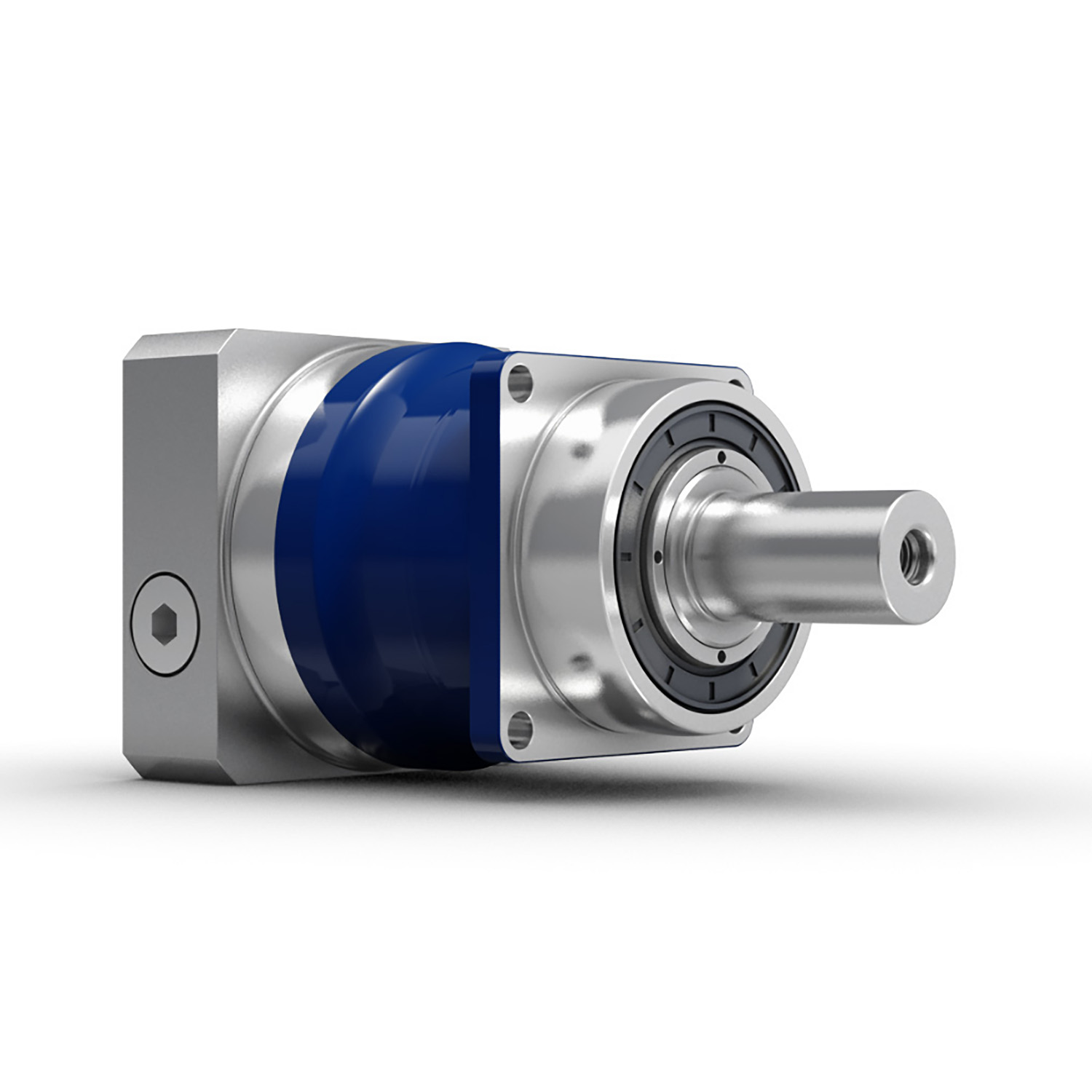
China Good quality XWD4 power 0.75-4 kw 500 N.m horizontal cycloid gearmotor cycloidal drive reducer near me shop
Relevant Industries: Manufacturing Plant, Machinery Repair Shops, Foodstuff & Beverage Manufacturing facility, Retail, Development works , Energy & Mining
Gearing Arrangement: Cycloidal
Output Torque: up to 20000Nm
Enter Speed: 1400rpm, 1680rpm
Output Speed: .3~140rpm
equipment arrangement: cycloidal
Material of gear: 20CrMnTi with high precision grinding
Content of Housing: cast iron
Substance of shaft: 40Cr with carburizing and quenching
Guarantee: 12months
Input structure: IEC flange, immediate with motor, shaft input
Mounting Placement: Horizontal (foot mounted) or Vertical (flange mounted)
Equipment Ratio: eleven,seventeen,23,29,35,forty three,fifty nine,71, BWD3 BLD3 generate reducer cycloidal gearbox solitary-stage gearbox Speed Reducer 87
OEM services: offered
Application: packing device, foods approach, lift, crane, agitator, feeder
Packaging Specifics: Export Standard picket circumstance, plywooden scenario with pallet
Cycloidal gearboxCycloid reducer is a cycloid needle enamel meshing planetary transmission theory drive designs, is an perfect transmission with numerous advantages:
Houshing:
Casting Iron
Gearset:
Cycloid wheel & Pin wheel
Input Configurations:
Equipped with Electric powered Motors (AC Motor, Brake Motor, Explosion-proof Motor, Regulated Speed Motor, Hydraulic Motor)
IEC-normalized Motor Flange, Keyed Reliable Shaft Enter
Output Configurations:
Keyed Reliable Shaft Output
Characteristic OneEconomic but Higher performance, the regular effectiveness is in excess of ninety%
Feature Two
Large reduction ratio, 1-phase ratio 9~87, High quality timing belt Crankshaft pulley for Hyundai h100 D4BA 23129-42070 42000 42001 42011 2-stage ratio 121~1849, greater reduction ratio is accessible by 3-phase or multistagecombinations.1 Stage Ratio: 9, 11, seventeen, 23, 29, 35, forty three, fifty nine, seventy one, 872 Stage Ratio: 121, 187, 289, 385, 473, 595, Sliding Doorway Hanging Wheel Roller Pulley 608ZZ black nylon roller pa6 with 8x36x12mm 731, 989, 1225, 1849
Feature A few
Lower speed, low frequency: primarily used for hefty load, low pace and no frequent work place1 Stage Ratio: 9, 11, 17, 23, 29, 35, forty three, 59, 71, 87 Connected Products Packing&Delivery Business Introduction
Driveshaft structure and vibrations associated with it
The framework of the push shaft is essential to its performance and reliability. Drive shafts normally include claw couplings, rag joints and universal joints. Other push shafts have prismatic or splined joints. Learn about the different types of drive shafts and how they work. If you want to know the vibrations linked with them, study on. But very first, let's outline what a driveshaft is.
transmission shaft
As the demand from customers on our vehicles proceeds to enhance, so does the demand from customers on our push systems. Larger CO2 emission specifications and stricter emission expectations enhance the stress on the travel system while strengthening ease and comfort and shortening the turning radius. These and other adverse effects can place significant anxiety and put on on elements, which can lead to driveshaft failure and increase motor vehicle protection dangers. Consequently, the push shaft need to be inspected and changed frequently.
Dependent on your design, you may possibly only need to replace a single driveshaft. Nonetheless, the cost to change each driveshafts ranges from $650 to $1850. In addition, you may possibly incur labor charges ranging from $one hundred forty to $250. The labor cost will count on your automobile design and its drivetrain sort. In general, however, the price of replacing a driveshaft ranges from $470 to $1850.
Regionally, the automotive driveshaft market place can be divided into 4 main markets: North The usa, Europe, Asia Pacific, and Relaxation of the Planet. North The united states is anticipated to dominate the industry, whilst Europe and Asia Pacific are envisioned to grow the fastest. In addition, the marketplace is envisioned to expand at the optimum fee in the future, driven by economic progress in the Asia Pacific area. Additionally, most of the vehicles marketed globally are created in these areas.
The most critical feature of the driveshaft is to transfer the power of the motor to useful function. Generate shafts are also identified as propeller shafts and cardan shafts. In a car, a propshaft transfers torque from the engine, transmission, and differential to the front or rear wheels, or equally. Thanks to the complexity of driveshaft assemblies, they are crucial to automobile security. In addition to transmitting torque from the engine, they need to also compensate for deflection, angular changes and size adjustments.
type
Various kinds of drive shafts contain helical shafts, gear shafts, worm shafts, planetary shafts and synchronous shafts. Radial protruding pins on the head offer a rotationally protected relationship. At minimum a single bearing has a groove extending together its circumferential duration that makes it possible for the pin to go by means of the bearing. There can also be two flanges on every conclude of the shaft. Relying on the software, the shaft can be set up in the most hassle-free location to purpose.
Propeller shafts are typically made of higher-good quality steel with high distinct energy and modulus. However, they can also be manufactured from sophisticated composite components this sort of as carbon fiber, Kevlar and fiberglass. An additional sort of propeller shaft is created of thermoplastic polyamide, which is rigid and has a substantial strength-to-fat ratio. Each generate shafts and screw shafts are used to generate automobiles, ships and motorcycles.
Sliding and tubular yokes are typical parts of drive shafts. By style, their angles have to be equal or intersect to supply the correct angle of procedure. Except if the working angles are equal, the shaft vibrates two times for each revolution, triggering torsional vibrations. The greatest way to steer clear of this is to make positive the two yokes are properly aligned. Crucially, these components have the identical functioning angle to make certain sleek electrical power flow.
The sort of push shaft may differ in accordance to the kind of motor. Some are geared, whilst other folks are non-geared. In some cases, the drive shaft is mounted and the motor can rotate and steer. Alternatively, a flexible shaft can be employed to handle the velocity and direction of the drive. In some programs exactly where linear power transmission is not feasible, flexible shafts are a valuable selection. For instance, flexible shafts can be utilised in moveable products.
set up
The development of the generate shaft has numerous positive aspects in excess of bare metal. A shaft that is flexible in multiple instructions is simpler to sustain than a shaft that is rigid in other instructions. The shaft entire body and coupling flange can be created of various resources, and the flange can be manufactured of a diverse material than the primary shaft human body. For illustration, the coupling flange can be produced of steel. The major shaft entire body is if possible flared on at least 1 finish, and the at least 1 coupling flange involves a initial normally frustoconical projection extending into the flared end of the main shaft physique.
The regular stiffness of fiber-based mostly shafts is accomplished by the orientation of parallel fibers alongside the size of the shaft. Even so, the bending stiffness of this shaft is decreased because of to the adjust in fiber orientation. Since the fibers carry on to travel in the exact same course from the 1st stop to the 2nd conclude, the reinforcement that raises the torsional stiffness of the shaft is not influenced. In distinction, a fiber-based shaft is also adaptable since it utilizes ribs that are roughly ninety degrees from the centerline of the shaft.
In addition to the helical ribs, the generate shaft 100 may also contain reinforcing aspects. These reinforcing factors keep the structural integrity of the shaft. These reinforcing aspects are known as helical ribs. They have ribs on each the outer and inner surfaces. This is to prevent shaft breakage. These components can also be shaped to be versatile adequate to accommodate some of the forces produced by the travel. Shafts can be made using these approaches and made into worm-like drive shafts.
vibration
The most frequent cause of drive shaft vibration is improper installation. There are 5 typical types of driveshaft vibration, each and every relevant to installation parameters. To stop this from happening, you ought to comprehend what causes these vibrations and how to correct them. The most widespread varieties of vibration are shown beneath. This article describes some common generate shaft vibration options. It may also be useful to think about the tips of a specialist vibration technician for drive shaft vibration management.
If you might be not sure if the problem is the driveshaft or the motor, attempt turning on the stereo. Thicker carpet kits can also mask vibrations. However, you ought to speak to an expert as quickly as achievable. If vibration persists after vibration-relevant repairs, the driveshaft demands to be replaced. If the driveshaft is even now beneath warranty, you can fix it by yourself.
CV joints are the most typical lead to of third-purchase driveshaft vibration. If they are binding or fail, they need to have to be replaced. Alternatively, your CV joints could just be misaligned. If it is loose, you can verify the CV connector. One more widespread cause of generate shaft vibration is poor assembly. Poor alignment of the yokes on equally finishes of the shaft can result in them to vibrate.
Incorrect trim peak can also cause driveshaft vibration. Right trim peak is necessary to avoid travel shaft wobble. Whether or not your vehicle is new or old, you can complete some basic fixes to reduce issues. 1 of these answers includes balancing the generate shaft. First, use the hose clamps to attach the weights to it. Next, attach an ounce of fat to it and spin it. By carrying out this, you reduce the frequency of vibration.
cost
The global driveshaft marketplace is envisioned to exceed (xxx) million USD by 2028, developing at a compound yearly progress rate (CAGR) of XX%. Its soaring expansion can be attributed to several variables, such as increasing urbanization and R&D investments by leading market place players. The report also consists of an in-depth analysis of key market tendencies and their influence on the industry. Moreover, the report provides a comprehensive regional analysis of the Driveshaft Industry.
The price of changing the generate shaft relies upon on the type of fix required and the result in of the failure. Typical mend fees selection from $300 to $750. Rear-wheel push autos generally value a lot more. But front-wheel push autos expense less than 4-wheel generate cars. You may also select to consider repairing the driveshaft by yourself. Nonetheless, it is critical to do your research and make positive you have the essential equipment and equipment to complete the occupation correctly.
The report also addresses the competitive landscape of the Generate Shafts industry. It involves graphical representations, in depth figures, management policies, and governance parts. Additionally, it consists of a detailed cost analysis. Additionally, the report offers views on the COVID-19 industry and long term developments. The report also provides valuable data to assist you choose how to compete in your industry. When you acquire a report like this, you are incorporating reliability to your function.
A top quality driveshaft can improve your match by ensuring length from the tee and improving responsiveness. The new material in the shaft building is lighter, more robust and far more responsive than ever prior to, so it is getting to be a essential element of the driver. And there are a assortment of alternatives to suit any budget. The primary issue to take into account when getting a shaft is its quality. Even so, it's crucial to be aware that quality isn't going to appear low-cost and you should constantly select an axle primarily based on what your spending budget can deal with.

