Product Description
Product Description
Product Description:
High Power 63mm DC Worm Gear Motor
Upgrade to the High Power version of the 63mm DC worm gear motor from HangZhou Xihu (West Lake) Dis. Motor Co., Ltd. for optimal performance in high-power applications.
Key Features:
- Designed with a 50A stall current for maximum power
- Available with a 48CPR encoder for precise control
- Option to include a back shaft for added versatility
- Choose between a metal brush or carbon brush for customized performance
For reliable power and precision, the 63mm DC worm gear motor is the perfect choice for your project. Upgrade to the High Power version today!
63mm,76mm turboworm gear box motor, low noise and small load torque selection of plastic gear of POM material, there is no requirement for noise, but the choice of metal gear with large load torque. The motor is used in rolling gates, automatic fence doors, glass doors, wipers, wheelchairs, various lifting equipment, kitchen supplies, and other products.
The encoder can be used as a low-cost servo motor and has the same function. Equipped with left and right gearboxes can be used symmetrically, using rolling shafts and oil-bearing to meet various scenarios. Various parameters can be adjusted according to customer requirements, the maximum torque of 12V/24V is 50N.m, for the speed of 10RPM.
| voltage VDC |
no load speed RPM |
no load current A |
load torque KG.CM |
on load speed RPM |
power W |
ratio |
| 12 | 80 | 1.8 | 60 | 68 | 80 | 60:1 |
| 12 | 130 | 1.2 | 33 | 110 | 30 | 20:1 |
| 12 | 150 | 1.2 | 45 | 130 | 30 | 20:1 |
| 12 | 170 | 1.4 | 35 | 150 | 45 | 24:1 |
| 24 | 30 | 1.4 | 60 | 25 | 30 | 60:1 |
| 24 | 65 | 120 | 50 | 60 | 80 | 20:1 |
| 24 | 210 | 1.0 | 40 | 180 | 45 | 75:1 |
Detailed Photos
Product Parameters
Certifications
Packaging & Shipping
Installation Instructions
Company Profile
FAQ
/* January 22, 2571 19:08:37 */!function(){function s(e,r){var a,o={};try{e&&e.split(",").forEach(function(e,t){e&&(a=e.match(/(.*?):(.*)$/))&&1
| Application: | DC Worm Gear Motor |
|---|---|
| Operating Speed: | Low Speed |
| Excitation Mode: | Excited |
| Function: | Driving |
| Casing Protection: | Open Type |
| Number of Poles: | 2 |
| Customization: |
Available
| Customized Request |
|---|

What are the considerations for choosing the appropriate lubrication for gear reducers?
Choosing the appropriate lubrication for gear reducers is crucial for ensuring optimal performance, longevity, and efficiency. Several considerations should be taken into account when selecting the right lubrication:
1. Load and Torque: The magnitude of the load and torque transmitted by the gear reducer affects the lubrication's viscosity and film strength requirements. Heavier loads may necessitate higher viscosity lubricants.
2. Operating Speed: The speed at which the gear reducer operates impacts the lubrication's ability to maintain a consistent and protective film between gear surfaces.
3. Temperature Range: Consider the temperature range of the operating environment. Lubricants with suitable viscosity indexes are crucial to maintaining performance under varying temperature conditions.
4. Contaminant Exposure: If the gear reducer is exposed to dust, dirt, water, or other contaminants, the lubrication should have proper sealing properties and resistance to contamination.
5. Lubrication Interval: Determine the desired maintenance interval. Some lubricants require more frequent replacement, while others offer extended operational periods.
6. Compatibility with Materials: Ensure that the chosen lubricant is compatible with the materials used in the gear reducer, including gears, bearings, and seals.
7. Noise and Vibration: Some lubricants have properties that can help reduce noise and dampen vibrations, improving the overall user experience.
8. Environmental Impact: Consider environmental regulations and sustainability goals when selecting lubricants.
9. Manufacturer Recommendations: Follow the manufacturer's recommendations and guidelines for lubrication type, viscosity grade, and maintenance intervals.
10. Monitoring and Analysis: Implement a lubrication monitoring and analysis program to assess lubricant condition and performance over time.
By carefully evaluating these considerations and consulting with lubrication experts, industries can choose the most suitable lubrication for their gear reducers, ensuring reliable and efficient operation.

Can gear reducers be used for both speed reduction and speed increase?
Yes, gear reducers can be utilized for both speed reduction and speed increase, depending on their design and arrangement. The functionality to either decrease or increase rotational speed is achieved by altering the arrangement of gears within the gearbox.
1. Speed Reduction: In speed reduction applications, a gear reducer is designed with gears of different sizes. The input shaft connects to a larger gear, while the output shaft is connected to a smaller gear. As the input shaft rotates, the larger gear turns the smaller gear, resulting in a decrease in output speed compared to the input speed. This configuration provides higher torque output at a lower speed, making it suitable for applications that require increased force or torque.
2. Speed Increase: For speed increase, the gear arrangement is reversed. The input shaft connects to a smaller gear, while the output shaft is connected to a larger gear. As the input shaft rotates, the smaller gear drives the larger gear, resulting in an increase in output speed compared to the input speed. However, the torque output is lower than that of speed reduction configurations.
By choosing the appropriate gear ratios and arrangement, gear reducers can be customized to meet specific speed and torque requirements for various industrial applications. It's important to select the right type of gear reducer and configure it correctly to achieve the desired speed reduction or speed increase.

How do gear reducers contribute to speed reduction and torque increase?
Gear reducers play a crucial role in mechanical systems by achieving speed reduction and torque increase through the principle of gear ratios. Here's how they work:
Gear reducers consist of multiple gears with different sizes, known as gear pairs. These gears are meshed together, and their teeth interlock to transmit motion and power. The gear ratio is determined by the ratio of the number of teeth on the input gear (driver) to the number of teeth on the output gear (driven).
Speed Reduction: When a larger gear (output gear) is driven by a smaller gear (input gear), the output gear rotates at a slower speed than the input gear. This reduction in speed is proportional to the gear ratio. As a result, gear reducers are used to slow down the rotational speed of the output shaft compared to the input shaft.
Torque Increase: The interlocking teeth of gears create a mechanical advantage that allows gear reducers to increase torque output. When the input gear applies a force (torque) to the teeth, it is transmitted to the output gear with greater force due to the leverage provided by the larger diameter of the output gear. The torque increase is inversely proportional to the gear ratio and is essential for applications requiring high torque at lower speeds.
By selecting appropriate gear ratios and arranging gear pairs, gear reducers can achieve various speed reduction and torque multiplication factors, making them essential components in machinery and equipment where precise control of speed and torque is necessary.


editor by CX 2024-04-02
China high quality Speed Ratio 15-100: 1 Helical Planet Nb115mm Reducer for Servo Motor DC CNC Round Flange Planetary Gearbox Gear gearbox adjustment
Product Description
Product Description
The NB115 series planetary gearboxes are designed and machined as a single unit with special tapered roller bearings to provide high radial load, high torque, ultra-precision, and small size. The ND series uses in highly rigid industries such as fiber optic laser equipment, floor track equipment, robot seventh axis, Parallel robots (spider hand) machine tools, and rotating arms.
Product Name: High Precision Planetary Reducer
Product Series: NB115 Series
Product features: high torque, high load, ultra-precision, small size
Product Description:
Integrated design concept with high-strength bearings ensure the product itself is durable and efficient
A variety of output ideas such as shaft output, flange and gear are available.
1 arc minute ≤ backlash ≤ 3 arc minutes
Reduction ratios ranging from 3 to 100
Frame design: increases torque and optimizes power transmission
Optimised selection of oil seals: reduces friction and laminate transmission efficiency
Protection class IP65
Warranty: 2 years
Our Advantages
High torque
High load
ultra-precision
Small size
Detailed Photos
Product Parameters
| Segment number | Double segment | |||||||||||||
| Ratio | i | 15 | 20 | 25 | 30 | 35 | 40 | 45 | 50 | 60 | 70 | 80 | 90 | 100 |
| Rated output torque | Nm | 190 | 270 | 310 | 290 | 280 | 240 | 210 | 310 | 290 | 280 | 240 | 210 | 210 |
| Emergency stop torque | Nm | Three times of Maximum Output Torque | ||||||||||||
| Rated input speed | Rpm | 4000 | ||||||||||||
| Max input speed | Rpm | 8000 | ||||||||||||
| Ultraprecise backlash | arcmin | ≤3 | ||||||||||||
| Precision backlash | arcmin | ≤5 | ||||||||||||
| Standard backlash | arcmin | ≤7 | ||||||||||||
| Torsional rigidity | Nm/arcmin | 25 | ||||||||||||
| Max.bending moment | Nm | 6700 | ||||||||||||
| Max.axial force | N | 3350 | ||||||||||||
| Service life | hr | 20000(10000 under continuous operation) | ||||||||||||
| Efficiency | % | ≥94% | ||||||||||||
| Weight | kg | 9 | ||||||||||||
| Operating Temperature | ºC | -10ºC~+90ºC | ||||||||||||
| Lubrication | Synthetic grease | |||||||||||||
| Protection class | IP64 | |||||||||||||
| Mounting Position | All directions | |||||||||||||
| Noise level(N1=3000rpm,non-loaded) | dB(A) | ≤63 | ||||||||||||
| Rotary inertia | Kg·cm² | 0.47 | 0.44 | |||||||||||
Applicable Industries
Packaging Machinery Mechanical Hand Textile Machinery
Non Standard automation Machine Tool Printing Equipment
Certifications
Company Profile
DESBOER (HangZhou) Transmission Technology Co., Ltd. is a subsidiary of DESBOER (China), which is committed to the design, development, customized production and sales of high precision planetary reducer as 1 of the technology company. Our company has over 10 years of design, production and sales experience, the main products are the high precision planetary reducer, gear, rack, etc., with high quality, short delivery period, high cost performance and other advantages to better serve the demand of global customers. It is worth noting that we remove the intermediate link sale from the factory directly to customers, so that you can get the most ideal price and also get our best quality service simultaneously.
About Research
In order to strengthen the advantages of products in the international market, the head company in Kyoto, Japan to established KABUSHIKIKAISYA KYOEKI, mainly engaged in the development of DESBOER high precision planetary reducer, high precision of transmission components such as the development work, to provide the most advanced design technology and the most high-quality products for the international market.
/* March 10, 2571 17:59:20 */!function(){function s(e,r){var a,o={};try{e&&e.split(",").forEach(function(e,t){e&&(a=e.match(/(.*?):(.*)$/))&&1
| Application: | Motor, Machinery, Marine, Agricultural Machinery, CNC Machine |
|---|---|
| Function: | Change Drive Torque, Speed Changing, Speed Reduction |
| Layout: | Plantery Type |
| Hardness: | Hardened Tooth Surface |
| Installation: | All Directions |
| Step: | Double-Step |
| Customization: |
Available
| Customized Request |
|---|

How do gear reducers enhance the efficiency of conveyor systems and robotics?
Gear reducers play a significant role in improving the efficiency of both conveyor systems and robotics by optimizing speed, torque, and control. Here's how they contribute:
Conveyor Systems:
In conveyor systems, gear reducers enhance efficiency in the following ways:
- Speed Control: Gear reducers allow precise control over the rotational speed of conveyor belts, ensuring that materials are transported at the desired speed for efficient production processes.
- Torque Adjustment: By adjusting gear ratios, gear reducers provide the necessary torque to handle varying loads and prevent overloading, minimizing energy wastage.
- Reverse Operation: Gear reducers enable smooth bidirectional movement of conveyor belts, facilitating tasks such as loading, unloading, and distribution without the need for additional components.
- Synchronization: Gear reducers ensure synchronized movement of multiple conveyor belts in complex systems, optimizing material flow and minimizing jams or bottlenecks.
Robotics:
In robotics, gear reducers enhance efficiency through the following means:
- Precision Movement: Gear reducers provide precise control over the movement of robot joints and arms, enabling accurate positioning and manipulation of objects.
- Reduced Inertia: Gear reducers help reduce the inertia experienced by robotic components, allowing for quicker and more responsive movements while conserving energy.
- Compact Design: Gear reducers offer a compact and lightweight solution for achieving various motion profiles in robotic systems, allowing for efficient use of space and resources.
- Torque Amplification: By amplifying torque from the motor, gear reducers enable robots to handle heavier loads and perform tasks that require greater force, enhancing their overall capabilities.
By providing precise speed control, torque adjustment, and reliable motion transmission, gear reducers optimize the performance of conveyor systems and robotics, leading to improved efficiency, reduced energy consumption, and enhanced operational capabilities.

How do gear reducers handle shock loads and sudden changes in torque?
Gear reducers are designed to handle shock loads and sudden changes in torque through several mechanisms that enhance their durability and reliability in challenging operating conditions.
1. Robust Construction: Gear reducers are constructed using high-strength materials and precision manufacturing techniques. This ensures that the gears, bearings, and other components can withstand sudden impacts and high torque fluctuations without deformation or failure.
2. Shock-Absorbing Features: Some gear reducer designs incorporate shock-absorbing features, such as flexible couplings, elastomeric elements, or torsionally flexible gear designs. These features help dampen and dissipate the energy from sudden shocks or torque spikes, reducing the impact on the entire system.
3. Torque Limiters: In applications where shock loads are common, torque limiters may be integrated into the gear reducer. These devices automatically disengage or slip when a certain torque threshold is exceeded, preventing damage to the gears and other components.
4. Overload Protection: Gear reducers can be equipped with overload protection mechanisms, such as shear pins or torque sensors. These mechanisms detect excessive torque and disengage the drive temporarily, allowing the system to absorb the shock or adjust to the sudden torque change.
5. Proper Lubrication: Adequate lubrication is essential for managing shock loads and sudden torque changes. High-quality lubricants reduce friction and wear, helping the gear reducer withstand dynamic forces and maintain smooth operation.
6. Dynamic Load Distribution: Gear reducers distribute dynamic loads across multiple gear teeth, which helps prevent localized stress concentrations. This feature minimizes the risk of tooth breakage and gear damage when subjected to sudden changes in torque.
By incorporating these design features and mechanisms, gear reducers can effectively handle shock loads and sudden changes in torque, ensuring the longevity and reliability of various industrial and mechanical systems.

Are there variations in gear reducer designs for specific tasks and applications?
Yes, gear reducer designs vary widely to suit specific tasks and applications across various industries. Manufacturers offer a range of gear reducer types and configurations to accommodate different requirements, including:
- Helical Gear Reducers: These are versatile and provide smooth and efficient torque transmission. They are commonly used in applications requiring high precision and moderate speed reduction, such as conveyors, mixers, and agitators.
- Bevel Gear Reducers: These are ideal for transmitting power between intersecting shafts. They are often used in heavy machinery, printing presses, and automotive applications.
- Worm Gear Reducers: These provide compact solutions and are suitable for applications with higher speed reduction requirements, such as conveyor systems, winches, and elevators.
- Planetary Gear Reducers: These offer high torque density and are used in applications demanding precise control, such as robotics, aerospace, and heavy-duty machinery.
- Parallel Shaft Gear Reducers: Commonly used in industrial machinery, these reducers are designed for high torque and reliability.
- Right-Angle Gear Reducers: These are used when space limitations require a change in shaft direction, commonly found in packaging equipment and conveyors.
Each type of gear reducer has unique features and benefits that make it suitable for specific tasks. Manufacturers often provide customization options to tailor gear reducers to the precise requirements of an application, including gear ratios, mounting options, and input/output configurations.
Therefore, the variation in gear reducer designs allows industries to select the most appropriate type based on factors such as torque, speed, space constraints, precision, and environmental conditions.
editor by CX 2024-01-18
China Professional Spare Part Gear Planetary Gearbox Speed Transmission Reducer for Stepper and Servo DC Motor gearbox definition
Product Description
Product Description:
Planetar gearbox is a kind of reducer with wide versatility. The inner gear adopts low carbon alloy steel carburizing quenching and grinding or nitriding process. Planetary gearbox has the characteristics of small structure size, large output torque, high speed ratio, high efficiency, safe and reliable performance, etc. The inner gear of the planetary gearbox can be divided into spur gear and helical gear.
Technical parameter:
| Section number | single section | ||||||||
| Reduction ratio | i | 3 | 4 | 5 | 6 | 7 | 8 | 9 | 10 |
| Rated output torque (Ta) | Nm | 55 | 50 | 60 | 55 | 50 | 45 | 40 | 40 |
| Emergency stop torque (Tzwor*) | Nm | Three times the rated output torque | |||||||
| Rated input speed (n) | rpm | 5000 | |||||||
| Maximum input speed (na) | rpm | 1000o | |||||||
| Ultra-precision backlash (PO) | arcmin | - | |||||||
| Precision backlash (P1) | arcmin | ≤3 | |||||||
| Standard backlash (P2) | arcmin | ≤5 | |||||||
| Torsional rigidity | Nm/arcmin | 7 | |||||||
| Allowable radial force | N | 1530 | |||||||
| allowable axial force | N | 765 | |||||||
| service life | hr | 20000 | |||||||
| effectiveness (n) | % | ≥97% | |||||||
| weight | kg | 1.3 | |||||||
| Operating temperature | ºC | -10°ºC~+90°ºC | |||||||
| lubricating | Synthetic grease | ||||||||
| Protection class | IP64 | ||||||||
| Installation direction | any direction | ||||||||
| Noise value(n1=3000rpm,no load) | dB(A) | ≤58 | |||||||
| Moment of inertia (J) | kg-cm' | 0.16 0.14 0.13 | |||||||
Picture:
Rear Reducer features:
1. High-quality aluminum alloy, light in weight and non-rusting.
2. Large in output torque.
3. Smooth running and low noise,durable in dreadful conditions.
4. High radiation efficiency.
5. Good-looking appearance, durable in service life and small volume.
6. Suitable for omnibearing installation.
Company Information:
HangZhou ChangLong Motor Co.,Ltd
( original HangZhou LINNAN Special Motor Factory)
With 20 years' hard working on developing , designing and manufacturing the high-speed electrical spindle, we have got our new GDZ-series electrical spindle, which is well recognized by clients for its great and stable quality after being put large quantities to the market. We provide quality guarantee and after-sales service for all of our products with the free manual work and the cost price for the materials or fittings.
FAQ:
How about the warrantly about your company?
bearings=half a year, other parts a year
Which kinds of bearing you are using?
It will according to your order. We have different price range for you with different bearing.
Do you have other spare parts for spindle motor, just like gripper, VFD, collet ?
We have all kits.And we can let engineers help you to program them.
Can I visit your factory?
Yes, welcome to our factory.
Do you have installation page?
Yes,we have.
Can you show me the inspection report ?
Yes We will send you inspection report of spindle after you send me full money before despatch.
The reasen is that I'm not sure which spindle will be sent to you.Every spindle have it's inspection report .And they are different in details.Only if you pay the money,we can decide which spindle to deliver you.
We also have spindle motor matching inverter(VFD), collet , gripper etc.
If you need other kinds of parts, please don't hesitate to contact us.
| Application: | Motor, Electric Cars, Motorcycle, Machinery, Marine, Toy, Agricultural Machinery |
|---|---|
| Function: | Distribution Power, Change Drive Torque, Speed Changing, Speed Reduction |
| Layout: | Cycloidal |
| Hardness: | Hardened Tooth Surface |
| Step: | Double-Step |
| Type: | Planetary Gear Box |
| Customization: |
Available
| Customized Request |
|---|

Can you provide real-world examples of products that use gear reducer technology?
Certainly! Gear reducer technology is widely used in various industries and products to enhance performance and efficiency. Here are some real-world examples:
1. Industrial Machinery: Gear reducers are commonly used in manufacturing machinery, such as conveyor systems, material handling equipment, and assembly lines, where they help control speed and torque for precise operations.
2. Wind Turbines: Wind turbines utilize gear reducers to transform the low rotational speed of the wind turbine rotor into the higher speed needed for electricity generation, optimizing energy conversion.
3. Automotive Transmissions: Automobiles use gear reducers as part of their transmissions to optimize power delivery from the engine to the wheels, allowing the vehicle to operate efficiently at different speeds.
4. Robotics: Robotic systems rely on gear reducers to control the movement and articulation of robot arms, enabling precise and controlled motion for various applications.
5. Printing Presses: Gear reducers are integral to printing presses, ensuring accurate and synchronized movement of printing plates, rollers, and paper feed mechanisms.
6. Conveyor Belts: Conveyor systems in industries like mining, agriculture, and logistics use gear reducers to regulate the movement of materials along the conveyor belts.
7. Packaging Machinery: Gear reducers play a crucial role in packaging machines, controlling the speed and movement of packaging materials, filling mechanisms, and sealing components.
8. Cranes and Hoists: Cranes and hoists rely on gear reducers to lift heavy loads with precision and control, ensuring safe and efficient material handling.
9. Pumps and Compressors: Gear reducers are utilized in pumps and compressors to regulate fluid flow and pressure, optimizing energy usage in fluid transportation systems.
10. Agriculture Equipment: Tractors and other agricultural machinery use gear reducers to adjust the speed and power delivery for different tasks, such as plowing, planting, and harvesting.
These examples demonstrate the diverse applications of gear reducer technology across various industries, showcasing their role in enhancing efficiency, control, and performance in a wide range of products and systems.

What factors should be considered when selecting the right gear reducer?
Choosing the appropriate gear reducer involves considering several crucial factors to ensure optimal performance and efficiency for your specific application:
- 1. Torque and Power Requirements: Determine the amount of torque and power your machinery needs for its operation.
- 2. Speed Ratio: Calculate the required speed reduction or increase to match the input and output speeds.
- 3. Gear Type: Select the appropriate gear type (helical, bevel, worm, planetary, etc.) based on your application's torque, precision, and efficiency requirements.
- 4. Mounting Options: Consider the available space and the mounting configuration that suits your machinery.
- 5. Environmental Conditions: Evaluate factors such as temperature, humidity, dust, and corrosive elements that may impact the gear reducer's performance.
- 6. Efficiency: Assess the gear reducer's efficiency to minimize power losses and improve overall system performance.
- 7. Backlash: Consider the acceptable level of backlash or play between gear teeth, which can affect precision.
- 8. Maintenance Requirements: Determine the maintenance intervals and procedures necessary for reliable operation.
- 9. Noise and Vibration: Evaluate noise and vibration levels to ensure they meet your machinery's requirements.
- 10. Cost: Compare the initial cost and long-term value of different gear reducer options.
By carefully assessing these factors and consulting with gear reducer manufacturers, engineers and industry professionals can make informed decisions to select the right gear reducer for their specific application, optimizing performance, longevity, and cost-effectiveness.
Are there variations in gear reducer designs for specific tasks and applications?
Yes, gear reducer designs vary widely to suit specific tasks and applications across various industries. Manufacturers offer a range of gear reducer types and configurations to accommodate different requirements, including:
- Helical Gear Reducers: These are versatile and provide smooth and efficient torque transmission. They are commonly used in applications requiring high precision and moderate speed reduction, such as conveyors, mixers, and agitators.
- Bevel Gear Reducers: These are ideal for transmitting power between intersecting shafts. They are often used in heavy machinery, printing presses, and automotive applications.
- Worm Gear Reducers: These provide compact solutions and are suitable for applications with higher speed reduction requirements, such as conveyor systems, winches, and elevators.
- Planetary Gear Reducers: These offer high torque density and are used in applications demanding precise control, such as robotics, aerospace, and heavy-duty machinery.
- Parallel Shaft Gear Reducers: Commonly used in industrial machinery, these reducers are designed for high torque and reliability.
- Right-Angle Gear Reducers: These are used when space limitations require a change in shaft direction, commonly found in packaging equipment and conveyors.
Each type of gear reducer has unique features and benefits that make it suitable for specific tasks. Manufacturers often provide customization options to tailor gear reducers to the precise requirements of an application, including gear ratios, mounting options, and input/output configurations.
Therefore, the variation in gear reducer designs allows industries to select the most appropriate type based on factors such as torque, speed, space constraints, precision, and environmental conditions.
editor by CX 2023-12-01
China manufacturer High Performance High Quality Electric DC Brush Brushless Stepper Servo Gear Motor Planetary Gearbox Manufacture for Automation Solutions with Good quality
Product Description
Product Description
The reducer is generally used for low-speed and high-torque transmission equipment. The motor, internal combustion engine or other high-speed running power is used to achieve the purpose of deceleration by meshing with the large gear on the output shaft through a gear with a small number of teeth on the input shaft of the reducer. The reducer will also have several pairs of gears with the same principle to achieve the ideal reduction effect. The ratio of the number of teeth of the large and small gears is the transmission ratio.
| SPECIFICATIONS | STAGE | RATIO | RATED TORQUE (N.m) | ||
| PLE42-SW-42mm Planetry Gearbox | L1 | 4 | 9 | ||
| 5 | 9 | ||||
| 7 | 5 | ||||
| 10 | 5 | ||||
| L2 | 16 | 12 | |||
| 20 | 12 | ||||
| 25 | 10 | ||||
| 28 | 10 | ||||
| 35 | 10 | ||||
| 40 | 10 | ||||
| 50 | 10 | ||||
| 70 | 10 | ||||
| Adapted motor | ∅5-10/ ∅22-2/F31-M3 | ||||
| Rated Input Speed (rpm) | 3000/min | ||||
| Max Input Speed (rpm) | 6000/min | ||||
| Backlash | L1 | ≤15 Arcmin | |||
| L2 | ≤10 Arcmin | ||||
| Fault stop torque(N.m) | 2 times of rated torque | ||||
| Efficiency | L1 | 96% | |||
| L2 | 94% | ||||
| Average life span | 20000h | ||||
| Operating temperature | -10°~+90° | ||||
| Nosie | ≤60 db | ||||
| Weight (kg) | L1 | 0.25 | |||
| L2 | 0.35 | ||||
| IP | 54 | ||||
| Installation method | Any installation method | ||||
Production Range
42 Series Planetary Gearbox
Backlash: 10-15 arcmin
Ratio Selection:
L1: 4,5,7,10,
L2: 12,16,20,25,28,35,40,50,70
Frame Dimension: 42mm Input Flange
Gear Arrangement: Planetary Straight Teeth
60 Series Planetary Gearbox
Backlash: 10-15 arcmin
Ratio Selection:
L1: 4,5,7,10,
L2: 16,20,25,28,35,40,50,70
Frame Dimension: 60mm Input Flange
Gear Arrangement: Planetary Straight Teeth
90 Series Planetary Gearbox
Backlash: 10-15 arcmin
Ratio Selection:
L1: 4,5,7,10,
L2: 16,20,25,28,35,40,50,70
Frame Dimension: 90mm Input Flange
Gear Arrangement: Planetary Straight Teeth
Powder Metal Series Planetary Gearbox
Backlash: 10-15 arcmin
Ratio Selection:
L1: 4,5,7,10,
L2: 16,20,25,28,35,40,50,70
Frame Dimension: 42mm & 57mm
Gear Arrangement: Planetary Straight Teeth
Right Angle Series Planetary Gearbox
Backlash: 10-15 arcmin
Ratio Selection:
L1: 4,5,7,10,
L2: 16,20,25,28,35,40,50,70
Frame Dimension: 60mm & 90mm
Gear Arrangement: Planetary Straight Teeth
Application Field
Automatic Arms
Assembly Line
3D-Printer
Medical -Equipment
CNC Machine
Tapping Machine
Other Automation Devices
Why Choose Us
ZheJiang High Precision Gear Transmission Co., Ltd
Company Profile
ZheJiang High Precision Gear Transmission Co., Ltd located in HangZhou city, ZheJiang Province, China. It is a leading company dedicated in precision transmission parts and system research, manufacture and sales, various series of products are manufactured in its 5000 square CHINAMFG workshop, the precision planetary gearbox and gear motor are developed especially for solar energy industry and have served many large-scale solar projects worldwidely.
The research team has more than 15 years experiences in this field, who can ensure a punctual and efficient service to meet customer's specific needs. It has pasted the ISO9001 quality management system and CE, products have been exported to lots of countries with a wide range application in AGV, intelligent robot, logistic, industrial automation, solar energy, vessel, packaging and textile etc.Consistently, our goal is to promote the application of solar power industry in the world, and we believe it provides clean and sustainable energy for humanity to better protect our environment.
Teams
Certifications
FAQ
Q1:Which areas are your products mainly used in?
A:At present, we have 2 main products: precision planetary gear reducer and solar geared motor. Most of the precision planetary reducers are used in automation fields, such as medical equipment, 3D printers, door openers, tapping machines, CNC lathes and a series of automation equipment. In addition, our solar geared motors are used in photovoltaic power generation projects, which are mainly combined with rotary drives to drive solar panels to track sunlight.
Q2: How to choose the suitable planetary gearbox?
A :First of all, we need you to be able to provide relevant parameters. If you have a motor drawing, it will let us recommend a suitable gearbox for you faster. If not, we hope you can provide the following motor parameters: output speed, output torque, voltage, current, IP, noise, operating conditions, motor size and power, etc.
Q3: What is the price ?
A : The main determining factor for the price of each product is the order volume. You can communicate with us and let us understand each other. I believe that our prices, product quality and our services can definitely make you satisfied.
Q4: Do you provide customized service?
A: Yes, we provide customized services. You only need to put CHINAMFG your needs, and we will do our best to provide you with a plan, make plans, and try our best to meet your needs.
| Application: | Motor, Machinery, Marine, Agricultural Machinery, Laser Cutting Machine |
|---|---|
| Function: | Distribution Power, Change Drive Torque, Change Drive Direction, Speed Changing, Speed Reduction, Speed Increase |
| Layout: | Coaxial |
| Hardness: | Hardened Tooth Surface |
| Installation: | Vertical Type |
| Step: | Single-Step |
| Samples: |
US$ 45/Piece
1 Piece(Min.Order) | |
|---|
| Customization: |
Available
| Customized Request |
|---|

Handling Backlash and Ensuring Precise Positioning in Servo Gearboxes
Servo gearboxes play a critical role in minimizing backlash and ensuring precise positioning in motion control systems:
1. Reduced Backlash Gearing: Many servo gearboxes utilize reduced backlash gearing technology. This involves designing gears with tighter tolerances and improved meshing profiles, resulting in minimal play between gear teeth. This reduces or eliminates backlash, which is essential for accurate motion control.
2. Preloading: Some servo gearboxes employ preloading mechanisms to remove any gaps between gears. By applying a controlled axial load to the gears, the meshing teeth remain in constant contact, eliminating backlash and enhancing precision.
3. Stiffness and Rigidity: Servo gearboxes are designed to be stiff and rigid, which helps minimize elastic deformation under load. This stiffness prevents gear teeth from deflecting, reducing the potential for backlash and maintaining accurate positioning.
4. High Gear Meshing Quality: The manufacturing process of servo gearboxes focuses on producing high-quality gears with precise tooth profiles and minimal manufacturing variations. This ensures consistent and smooth gear meshing, minimizing the likelihood of backlash.
5. Closed-Loop Control: Combining servo gearboxes with closed-loop control systems allows for real-time feedback on position and speed. Any deviation from the desired position can be quickly corrected by adjusting the motor's output, compensating for any inherent backlash and ensuring precise positioning.
6. Advanced Gear Coatings: Some servo gearboxes incorporate advanced gear coatings or treatments that improve the meshing characteristics and reduce friction. This contributes to smoother gear engagement and minimizes backlash effects.
7. Inertia Matching: Properly matching the inertia of the load to the servo motor and gearbox combination reduces the likelihood of overshooting or oscillations during positioning. Accurate inertia matching enhances the control system's ability to maintain precise positioning.
Servo gearboxes' ability to handle backlash and ensure precise positioning is crucial for applications that require high accuracy, such as robotics, CNC machines, and automated manufacturing processes. By employing advanced design techniques and technologies, servo gearboxes contribute to achieving repeatable and accurate motion control.

Real-World Examples of Products Using Servo Gearboxes
Servo gearboxes find application in various industries and products, contributing to their precision, efficiency, and performance:
- Industrial Robots: Industrial robots utilize servo gearboxes to achieve precise and controlled movements, enabling tasks such as assembly, welding, and material handling.
- CNC Machines: Computer Numerical Control (CNC) machines use servo gearboxes for accurate positioning and control of cutting tools, resulting in high-quality and complex machining operations.
- Automated Packaging Machines: Servo gearboxes play a vital role in packaging machines by ensuring precise filling, sealing, and labeling of products, leading to consistent packaging quality.
- Medical Devices: Advanced medical devices like robotic surgical systems use servo gearboxes to provide surgeons with precise control and dexterity during minimally invasive procedures.
- Textile Machinery: Servo gearboxes are employed in textile machinery to control the movement of yarn, ensuring uniform and high-quality fabric production.
- Automated Material Handling Systems: Servo gearboxes enable automated conveyors, lifts, and sorting systems to handle materials efficiently and accurately in warehouses and distribution centers.
- Printers and Plotters: High-resolution printers and plotters use servo gearboxes to precisely position print heads and ensure accurate image reproduction.
- Food Processing Equipment: Servo gearboxes are integrated into food processing machines for tasks like slicing, portioning, and mixing, ensuring consistent product quality and yield.
- Pharmaceutical Manufacturing: Pharmaceutical machinery relies on servo gearboxes for precise dosage and filling operations, crucial for drug production.
- Aerospace Components: Aerospace systems, such as landing gear mechanisms and control surfaces, use servo gearboxes to achieve precise movement and ensure the safety of flight.
These examples demonstrate the widespread adoption of servo gearboxes across various industries, where precision, accuracy, and controlled motion are critical for efficient and high-performance operations.
Benefits of Using a Servo Gearbox for Precise Motion Control
Servo gearboxes offer several advantages when it comes to achieving precise motion control in various applications:
1. Accuracy: Servo gearboxes provide exceptional accuracy in speed and position control, making them suitable for applications that require tight tolerances and precise movements.
2. Low Backlash: These gearboxes are designed to minimize backlash, which is essential for eliminating lost motion and ensuring accurate positioning.
3. High Torque Density: Servo gearboxes offer a high torque-to-size ratio, allowing them to handle significant loads while maintaining a compact footprint.
4. Dynamic Performance: They excel in dynamic performance, enabling rapid changes in speed and direction with minimal overshoot or settling time.
5. Responsiveness: Servo gearboxes respond quickly to control signals, making them ideal for applications that require rapid adjustments and changes in direction.
6. Smooth Operation: These gearboxes provide smooth and precise movement, critical for applications like robotics, where jerky or uneven motion can lead to inaccuracies or damage.
7. Reduces Maintenance: The accuracy and durability of servo gearboxes can reduce wear and tear on other components, leading to lower maintenance requirements.
8. Improved Efficiency: Servo gearboxes offer high efficiency in power transmission, contributing to energy savings and minimizing heat generation.
9. Customization: They can be tailored to specific application needs, including factors like reduction ratios, mounting options, and feedback compatibility.
10. Versatility: Servo gearboxes find application in various industries, including robotics, CNC machining, medical equipment, and automation.
Overall, the benefits of using a servo gearbox for precise motion control make them an essential component in applications that demand accuracy, responsiveness, and reliable performance.
editor by CX 2023-11-14
China Good quality CZPT MD024024-144 24mm Gear Motor Supplier 32rpm 12V 24V DC Planetary Gear Motor Speed Reducer for Agricultural Planter gearbox engine
Product Description
CHINAMFG 24MM DC Planetary plastic gearbox brushless dc Gear Motor
Product Description
above specifications just for reference and customizable according to requirements.
| motor specifications:24mm brushless brush coreless motor | |
| motors (optional) | brushless dc motor,stepper motor,coreless motor |
| voltage(optional) | 3-24v |
| input speed | <=15000rpm |
| current | 300mA max |
| performance Data:24mm Planetary plastic Gearbox brush motor / brushless motor / Stepper Motor / Coreless Motor | |||||||
| Model | Rated Speed | Max Speed | Max Rated Torque | Max Instant Torque | Reduction Ratio | Gearbox Length | Overall Length |
| rpm | rpm | Kg.cm | Kg.cm | mm | mm | ||
| MD571571-4 | 1150 | 1500 | 20 | 60 | 4 | 19 | 49.8 |
| MD571571-6 | 767 | 1000 | 20 | 60 | 6 | 19 | 49.8 |
| MD571571-16 | 288 | 375 | 20 | 60 | 16 | 25 | 55.8 |
| MD571571-24 | 192 | 250 | 20 | 60 | 24 | 25 | 55.8 |
| MD571571-36 | 128 | 167 | 20 | 60 | 36 | 25 | 55.8 |
| MD571571-64 | 72 | 94 | 20 | 60 | 64 | 32 | 62.8 |
| MD571571-96 | 48 | 63 | 20 | 60 | 96 | 32 | 62.8 |
| MD571571-144 | 32 | 42 | 20 | 60 | 144 | 32 | 62.8 |
| MD571571-216 | 21 | 38 | 20 | 60 | 216 | 32 | 62.8 |
| MD571571-256 | 18 | 23 | 20 | 60 | 256 | 39 | 69.8 |
| MD571571-384 | 12 | 16 | 20 | 60 | 384 | 39 | 69.8 |
| MD571571-576 | 8 | 10 | 20 | 60 | 576 | 39 | 69.8 |
| MD571571-864 | 5 | 7 | 20 | 60 | 864 | 39 | 69.8 |
| MD571571-1296 | 4 | 5 | 20 | 60 | 1296 | 39 | 69.8 |
| * The above specifications are subject to change without prior notice. They are for reference only and can be customized as required. | |||||||
Please let us know your requirements and we will provide you with micro transmission solutions.
Product details show:
Application
| Smart wearable devices | watch,VR,AR,XR and etc. |
| Household application | kitchen appliances, sewing machines, corn popper, vacuum cleaner, garden tool, sanitary ware, window curtain, intelligent closestool, sweeping robot, power seat, standing desk, electric sofa, TV, computer, treadmill, spyhole, cooker hood, electric drawer, electric mosquito net, intelligent cupboard, intelligent wardrobe, automatic soap dispenser, UV baby bottle sterilizer, lifting hot pot cookware, dishwasher, washing machine, food breaking machine, dryer, air conditioning, dustbin, coffee machine, whisk,smart lock,bread maker,Window cleaning robot and etc. |
| communication equipment | 5G base station,video conference,mobile phone and etc. |
| Office automation equipments | scanners, printers, multifunction machines copy machines, fax (FAX paper cutter), computer peripheral, bank machine, screen, lifting socket, display,notebook PC and etc. |
| Automotive products | conditioning damper actuator, car DVD,door lock actuator, retractable rearview mirror, meters, optic axis control device, head light beam level adjuster, car water pump, car antenna, lumbar support, EPB, car tail gate electric putter, HUD, head-up display, vehicle sunroof, EPS, AGS, car window, head restraint, E-booster, car seat, vehicle charging station and etc. |
| Toys and models | radio control model, automatic cruise control, ride-on toy, educational robot, programming robot, medical robot, automatic feeder, intelligent building blocks, escort robot and etc. |
| Medical equipments | blood pressure meter, breath machine, medical cleaning pump, medical bed, blood pressure monitors, medical ventilator, surgical staplers, infusion pump, dental instrument, self-clotting cutter, wound cleaning pump for orthopedic surgery,electronic cigarette, eyebrow pencil,fascia gun, , surgical robot,laboratory automation and etc. |
| Industrials | flow control valves, seismic testing,automatic reclosing,Agricultural unmanned aerial vehicle,automatic feeder ,intelligent express cabinet and etc. |
| Electric power tools | electric drill, screwdriver,garden tool and etc. |
| Precision instruments | optics instruments,automatic vending machine, wire-stripping machine and etc. |
| Personal care | tooth brush, hair clipper, electric shaver, massager, vibrator, hair dryer, rubdown machine, scissor hair machine, foot grinder,anti-myopia pen, facial beauty equipment, hair curler,Electric threading knife,POWER PERFECT PORE, Puff machine,eyebrow tweezers and etc. |
| Consumer electronics | camera, mobile phone,digital camera, automatic retracting device,camcorder, kinescope DVD,headphone stereo, cassette tape recorder, bluetooth earbud charging case, turntable, tablet,UAV(unmanned aerial vehicle),surveillance camera,PTZ camera, rotating smart speaker and etc. |
| robots | educational robot, programming robot, medical robot, escort robot and etc. |
Company Profile
HangZhou CHINAMFG Machinery & Electronics Co., Ltd was established in 2001,We provide the total drive solution for customers from design, tooling fabrication, components manufacturing and assembly.
Workshop
Testing Equipment
1) Competitive Advantages
- 1) Competitive Advantages
19+year experience in manufacturing motor gearbox
We provide technical support from r&d, prototype, testing, assembly and serial production , ODM &OEM
Competitive Price
Product Performance: Low noise, High efficiency, Long lifespan
Prompt Delivery: 15 working days after payment
Small Orders Accepted
2) Main Products
-
Precision reduction gearbox and its diameter:3.4mm-38mm,voltage:1.5-24V,power: 0.01-40W,output speed:5-2000rpm and output torque:1.0 gf.cm -50kgf.cm,
- Customized worm and gear transmission machinery;
- Precise electromechanical motion module;
- Precise component and assembly of plastic and metal powder injection.
Our Services
- ODM & OEM
- Gearbox design and development
- Related technology support
- Micro drive gearbox custom solution
Packaging & Shipping
1) Packing Details
packed in nylon firstly, then carton, and then reinforced with wooden case for outer packing.
Or according to client's requirement.
2) Shipping Details
samples will be shipped within 10 days;
batch order leading time according to the actual situation.
Certifications
Certifications
We Have passed to hold ISO9001:2015(CN11/3571),ISO14001:2004(U006616E0153R3M), ISO13485:2016(CN18/42018) and IATF16949:2016(CN11/3571.01).
and more...
FAQ
FAQ
1. Can you make the gearbox with custom specifications?
YES. We have design and development team, also a great term of engineers, each of them have
many work years experience.
2.Do you provide the samples?
YES. Our company can provide the samples to you, and the delivery time is about 5-15days according to the specification of gearbox you need.
3.What is your MOQ?
Our MOQ is 2000pcs. But at the beginning of our business, we accept small order.
4. Do you have the item in stock?
I am sorry we donot have the item in stock, All products are made with orders.
5. Do you provide technology support?
YES. Our company have design and development team, we can provide technology support if you
need.
6.How to ship to us?
We will ship the goods to you according to the DHL or UPS or FEDEX etc account you provide.
7.How to pay the money?
We accept T/T in advance. Also we have different bank account for receiving money, like US dollors or RMB etc.
8. How can I know the product is suitable for me?
Frist, you need to provide us the more details information about the product. We will recommend the item to you according to your requirement of specification. After you confirm, we will prepare the samples to you. also we will offer some good advances according to your product use.
9. Can I come to your company to visit?
YES, you can come to our company to visit at anytime, and welcome to visit our company.
10. How do contact us ?
Please send an inquiry
| Application: | Universal, Industrial, Household Appliances, Car, Power Tools |
|---|---|
| Operating Speed: | High Speed |
| Excitation Mode: | Permanent Magnet |
| Function: | Control, Driving |
| Casing Protection: | Drip-Proof |
| Number of Poles: | 4 |
| Customization: |
Available
| Customized Request |
|---|

How do gear reducers contribute to energy efficiency in machinery and equipment?
Gear reducers play a significant role in enhancing energy efficiency in various machinery and equipment. Here's how they contribute:
1. Speed Reduction: Gear reducers are commonly used to reduce the speed of the input shaft, allowing the motor to operate at a higher speed where it's most efficient. This speed reduction helps match the motor's optimal operating range, reducing energy consumption.
2. Torque Increase: Gear reducers can increase torque output while decreasing speed, enabling machinery to handle higher loads without the need for a larger, more energy-intensive motor.
3. Matching Load Requirements: By adjusting gear ratios, gear reducers ensure that the machinery's output speed and torque match the load requirements. This prevents the motor from operating at unnecessary high speeds, saving energy.
4. Variable Speed Applications: In applications requiring variable speeds, gear reducers allow for efficient speed control without the need for continuous motor adjustments, improving energy usage.
5. Efficient Power Transmission: Gear reducers efficiently transmit power from the motor to the load, minimizing energy losses due to friction and inefficiencies.
6. Motor Downsizing: Gear reducers enable the use of smaller, more energy-efficient motors by converting their higher speed, lower torque output into the lower speed, higher torque needed for the application.
7. Decoupling Motor and Load Speeds: In cases where the motor and load speeds are inherently different, gear reducers ensure the motor operates at its most efficient speed while still delivering the required output to the load.
8. Overcoming Inertia: Gear reducers help overcome the inertia of heavy loads, making it easier for motors to start and stop, reducing energy consumption during frequent operation.
9. Precise Control: Gear reducers provide precise control over speed and torque, optimizing the energy consumption of machinery in processes that require accurate adjustments.
10. Regenerative Braking: In some applications, gear reducers can be used to capture and convert kinetic energy back into electrical energy during braking or deceleration, improving overall energy efficiency.
By efficiently managing speed, torque, and power transmission, gear reducers contribute to energy-efficient operation, reducing energy consumption, and minimizing the environmental impact of machinery and equipment.
What factors should be considered when selecting the right gear reducer?
Choosing the appropriate gear reducer involves considering several crucial factors to ensure optimal performance and efficiency for your specific application:
- 1. Torque and Power Requirements: Determine the amount of torque and power your machinery needs for its operation.
- 2. Speed Ratio: Calculate the required speed reduction or increase to match the input and output speeds.
- 3. Gear Type: Select the appropriate gear type (helical, bevel, worm, planetary, etc.) based on your application's torque, precision, and efficiency requirements.
- 4. Mounting Options: Consider the available space and the mounting configuration that suits your machinery.
- 5. Environmental Conditions: Evaluate factors such as temperature, humidity, dust, and corrosive elements that may impact the gear reducer's performance.
- 6. Efficiency: Assess the gear reducer's efficiency to minimize power losses and improve overall system performance.
- 7. Backlash: Consider the acceptable level of backlash or play between gear teeth, which can affect precision.
- 8. Maintenance Requirements: Determine the maintenance intervals and procedures necessary for reliable operation.
- 9. Noise and Vibration: Evaluate noise and vibration levels to ensure they meet your machinery's requirements.
- 10. Cost: Compare the initial cost and long-term value of different gear reducer options.
By carefully assessing these factors and consulting with gear reducer manufacturers, engineers and industry professionals can make informed decisions to select the right gear reducer for their specific application, optimizing performance, longevity, and cost-effectiveness.
What industries and machinery commonly utilize gear reducers?
Gear reducers are widely used across various industries and types of machinery for torque reduction and speed control. Some common industries and applications include:
- 1. Manufacturing: Gear reducers are used in manufacturing equipment such as conveyors, mixers, and packaging machines to control speed and transmit power efficiently.
- 2. Automotive: They are utilized in vehicles for applications like power transmission in transmissions and differentials.
- 3. Aerospace: Gear reducers are used in aircraft systems, including landing gear mechanisms and engine accessories.
- 4. Robotics and Automation: They play a crucial role in robotic arms, CNC machines, and automated production lines.
- 5. Mining and Construction: Gear reducers are used in heavy machinery like excavators, bulldozers, and crushers for power transmission and torque multiplication.
- 6. Energy and Power Generation: Wind turbines, hydroelectric generators, and other power generation equipment use gear reducers to convert rotational speed and transmit power.
- 7. Marine and Shipbuilding: They are used in ship propulsion systems, steering mechanisms, and anchor handling equipment.
- 8. Material Handling: Gear reducers are essential in conveyor systems, elevators, and hoists for controlled movement of materials.
- 9. Food and Beverage: They find applications in food processing equipment like mixers, grinders, and packaging machines.
- 10. Paper and Pulp: Gear reducers are used in machinery for pulp processing, paper production, and printing.
These examples represent just a fraction of the industries and machinery that benefit from the use of gear reducers to optimize power transmission and achieve the desired motion characteristics.
editor by CX 2023-10-31
China manufacturer Nmrv Worm Gearbox for DC Brake Motor Transmission differential gearbox
Product Description
Product Description
Main Materials:
1)housing:aluminium alloy ADC12(size 571-090); die cast iron HT200(size 110-150);
2)Worm:20Cr, ZI Involute profile; carbonize&quencher heat treatment make gear surface hardness up to 56-62 HRC; After precision grinding, carburization layer's thickness between 0.3-0.5mm.
3)Worm Wheel:wearable stannum alloy CuSn10-1
Detailed Photos
Combination Options:
Input:with input shaft, With square flange,With IEC standard input flange
Output:with torque arm, output flange, single output shaft, double output shaft, plastic cover
Worm reducers are available with diffferent combinations: NMRV+NMRV, NMRV+NRV, NMRV+PC, NMRV+UDL, NMRV+MOTORS
Exploded View:
Product Parameters
| Old Model |
New Model | Ratio | Center Distance | Power | Input Dia. | Output Dia. | Output Torque | Weight |
| RV571 | 7.5~100 | 25mm | 0.06KW~0.12KW | Φ9 | Φ11 | 21N.m | 0.7kgs | |
| RV030 | RW030 | 7.5~100 | 30mm | 0.06KW~0.25KW | Φ9(Φ11) | Φ14 | 45N.m | 1.2kgs |
| RV040 | RW040 | 7.5~100 | 40mm | 0.09KW~0.55KW | Φ9(Φ11,Φ14) | Φ18(Φ19) | 84N.m | 2.3kgs |
| RV050 | RW050 | 7.5~100 | 50mm | 0.12KW~1.5KW | Φ11(Φ14,Φ19) | Φ25(Φ24) | 160N.m | 3.5kgs |
| RV063 | RW063 | 7.5~100 | 63mm | 0.18KW~2.2KW | Φ14(Φ19,Φ24) | Φ25(Φ28) | 230N.m | 6.2kgs |
| RV075 | RW075 | 7.5~100 | 75mm | 0.25KW~4.0KW | Φ14(Φ19,Φ24,Φ28) | Φ28(Φ35) | 410N.m | 9.0kgs |
| RV090 | RW090 | 7.5~100 | 90mm | 0.37KW~4.0KW | Φ19(Φ24,Φ28) | Φ35(Φ38) | 725N.m | 13.0kgs |
| RV110 | RW110 | 7.5~100 | 110mm | 0.55KW~7.5KW | Φ19(Φ24,Φ28,Φ38) | Φ42 | 1050N.m | 35.0kgs |
| RV130 | RW130 | 7.5~100 | 130mm | 0.75KW~7.5KW | Φ24(Φ28,Φ38) | Φ45 | 1550N.m | 48.0kgs |
| RV150 | RW150 | 7.5~100 | 150mm | 2.2KW~15KW | Φ28(Φ38,Φ42) | Φ50 | 84.0kgs |
GMRV Outline Dimension:
| GMRV | A | B | C | C1 | D(H8) | E(h8) | F | G | G1 | H | H1 | I | M | N | O | P | Q | R | S | T | BL | β | b | t | V |
| 030 | 80 | 97 | 54 | 44 | 14 | 55 | 32 | 56 | 63 | 65 | 29 | 55 | 40 | 57 | 30 | 75 | 44 | 6.5 | 21 | 5.5 | M6*10(n=4) | 0° | 5 | 16.3 | 27 |
| 040 | 100 | 121.5 | 70 | 60 | 18(19) | 60 | 43 | 71 | 78 | 75 | 36.5 | 70 | 50 | 71.5 | 40 | 87 | 55 | 6.5 | 26 | 6.5 | M6*10(n=4) | 45° | 6 | 20.8(21.8) | 35 |
| 050 | 120 | 144 | 80 | 70 | 25(24) | 70 | 49 | 85 | 92 | 85 | 43.5 | 80 | 60 | 84 | 50 | 100 | 64 | 8.5 | 30 | 7 | M8*12(n=4) | 45° | 8 | 28.3(27.3) | 40 |
| 063 | 144 | 174 | 100 | 85 | 25(28) | 80 | 67 | 103 | 112 | 95 | 53 | 95 | 72 | 102 | 63 | 110 | 80 | 8.5 | 36 | 8 | M8*12(n=8) | 45° | 8 | 28.3(31.3) | 50 |
| 075 | 172 | 205 | 120 | 90 | 28(35) | 95 | 72 | 112 | 120 | 115 | 57 | 112.5 | 86 | 119 | 75 | 140 | 93 | 11 | 40 | 10 | M8*14(n=8) | 45° | 8(10) | 31.3(38.3) | 60 |
| 090 | 206 | 238 | 140 | 100 | 35(38) | 110 | 74 | 130 | 140 | 130 | 67 | 129.5 | 103 | 135 | 90 | 160 | 102 | 13 | 45 | 11 | M10*16(n=8) | 45° | 10 | 38.3(41.3) | 70 |
| 110 | 255 | 295 | 170 | 115 | 42 | 130 | - | 144 | 155 | 165 | 74 | 160 | 127.5 | 167.5 | 110 | 200 | 125 | 14 | 50 | 14 | M10*18(n=8) | 45° | 12 | 45.3 | 85 |
| 130 | 293 | 335 | 200 | 120 | 45 | 180 | - | 155 | 170 | 215 | 81 | 179 | 146.5 | 187.5 | 130 | 250 | 140 | 16 | 60 | 15 | M12*20(n=8) | 45° | 14 | 48.8 | 100 |
| 150 | 340 | 400 | 240 | 145 | 50 | 180 | - | 185 | 200 | 215 | 96 | 210 | 170 | 230 | 150 | 250 | 180 | 18 | 72.5 | 18 | M12*22(n=8) | 45° | 14 | 53.8 | 120 |
Company Profile
About CHINAMFG Transmission:
We are a professional reducer manufacturer located in HangZhou, ZHangZhoug province.
Our leading products is full range of RV571-150 worm reducers , also supplied GKM hypoid helical gearbox, GRC inline helical gearbox, PC units, UDL Variators and AC Motors, G3 helical gear motor.
Products are widely used for applications such as: foodstuffs, ceramics, packing, chemicals, pharmacy, plastics, paper-making, construction machinery, metallurgic mine, environmental protection engineering, and all kinds of automatic lines, and assembly lines.
With fast delivery, superior after-sales service, advanced producing facility, our products sell well both at home and abroad. We have exported our reducers to Southeast Asia, Eastern Europe and Middle East and so on.Our aim is to develop and innovate on basis of high quality, and create a good reputation for reducers.
Packing information:Plastic Bags+Cartons+Wooden Cases , or on request
We participate Germany Hannver Exhibition-ZheJiang PTC Fair-Turkey Win Eurasia
Logistics
After Sales Service
1.Maintenance Time and Warranty:Within 1 year after receiving goods.
2.Other Service: Including modeling selection guide, installation guide, and problem resolution guide, etc.
FAQ
1.Q:Can you make as per customer drawing?
A: Yes, we offer customized service for customers accordingly. We can use customer's nameplate for gearboxes.
2.Q:What is your terms of payment ?
A: 30% deposit before production,balance T/T before delivery.
3.Q:Are you a trading company or manufacturer?
A:We are a manufacurer with advanced equipment and experienced workers.
4.Q:What's your production capacity?
A:8000-9000 PCS/MONTH
5.Q:Free sample is available or not?
A:Yes, we can supply free sample if customer agree to pay for the courier cost
6.Q:Do you have any certificate?
A:Yes, we have CE certificate and SGS certificate report.
Contact information:
Ms Lingel Pan
For any questions just feel free ton contact me. Many thanks for your kind attention to our company!
| Application: | Motor, Machinery, Marine, Agricultural Machinery, Industry |
|---|---|
| Function: | Distribution Power, Change Drive Torque, Change Drive Direction, Speed Changing, Speed Reduction |
| Layout: | Right Angle |
| Hardness: | Hardened Tooth Surface |
| Installation: | Horizontal Type |
| Step: | Double-Step |
| Samples: |
US$ 12/Piece
1 Piece(Min.Order) | |
|---|
| Customization: |
Available
| Customized Request |
|---|

Self-Locking Properties in a Worm Gearbox
Yes, worm gearboxes exhibit self-locking properties, which can be advantageous in certain applications. Self-locking refers to the ability of a mechanism to prevent the transmission of motion from the output shaft back to the input shaft when the system is at rest. Worm gearboxes inherently possess self-locking properties due to the unique design of the worm gear and worm wheel.
The self-locking behavior arises from the angle of the helix on the worm shaft. In a properly designed worm gearbox, the helix angle of the worm is such that it creates a mechanical advantage that resists reverse motion. When the gearbox is not actively driven, the friction between the worm threads and the worm wheel teeth creates a locking effect.
This self-locking feature makes worm gearboxes particularly useful in applications where holding a load in position without external power is necessary. For instance, they are commonly used in situations where there's a need to prevent a mechanism from backdriving, such as in conveyor systems, hoists, and jacks.
However, it's important to note that while self-locking properties can be beneficial, they also introduce some challenges. The high friction between the worm gear and worm wheel during self-locking can lead to higher wear and heat generation. Additionally, the self-locking effect can reduce the efficiency of the gearbox when it's actively transmitting motion.
When considering the use of a worm gearbox for a specific application, it's crucial to carefully analyze the balance between self-locking capabilities and other performance factors to ensure optimal operation.
How to Calculate the Input and Output Speeds of a Worm Gearbox?
Calculating the input and output speeds of a worm gearbox involves understanding the gear ratio and the principles of gear reduction. Here's how you can calculate these speeds:
- Input Speed: The input speed (N1) is the speed of the driving gear, which is the worm gear in this case. It is usually provided by the manufacturer or can be measured directly.
- Output Speed: The output speed (N2) is the speed of the driven gear, which is the worm wheel. To calculate the output speed, use the formula:
N2 = N1 / (Z1 * i)
Where:
N2 = Output speed (rpm)
N1 = Input speed (rpm)
Z1 = Number of teeth on the worm gear
i = Gear ratio (ratio of the number of teeth on the worm gear to the number of threads on the worm)
It's important to note that worm gearboxes are designed for gear reduction, which means that the output speed is lower than the input speed. Additionally, the efficiency of the gearbox, friction, and other factors can affect the actual output speed. Calculating the input and output speeds is crucial for understanding the performance and capabilities of the worm gearbox in a specific application.

What is a Worm Gearbox and How Does It Work?
A worm gearbox, also known as a worm gear reducer, is a mechanical device used to transmit rotational motion and torque between non-parallel shafts. It consists of a worm screw and a worm wheel, both of which have helical teeth. The worm screw resembles a threaded cylinder, while the worm wheel is a gear with teeth that mesh with the worm screw.
The working principle of a worm gearbox involves the interaction between the worm screw and the worm wheel. When the worm screw is rotated, its helical teeth engage with the teeth of the worm wheel. As the worm screw rotates, it translates the rotational motion into a perpendicular motion, causing the worm wheel to rotate. This perpendicular motion allows the worm gearbox to achieve a high gear reduction ratio, making it suitable for applications that require significant speed reduction.
One of the key features of a worm gearbox is its ability to provide a high gear reduction ratio in a compact design. However, due to the sliding nature of the meshing teeth, worm gearboxes may exhibit higher friction and lower efficiency compared to other types of gearboxes. Therefore, they are often used in applications where efficiency is not the primary concern but where high torque and speed reduction are essential, such as conveyor systems, elevators, automotive steering systems, and certain industrial machinery.
editor by CX 2023-09-18
China manufacturer Customized Axle CNC Hydraulic Pump Motor DC Shaft/Pto Shaft
Product Description
Our advantage:
*Specialization in CNC formulations of high precision and quality
*Independent quality control department
*Control plan and process flow sheet for each batch
*Quality control in all whole production
*Meeting demands even for very small quantities or single units
*Short delivery times
*Online orders and production progress monitoring
*Excellent price-quality ratio
*Absolute confidentiality
*Various materials (stainless steel, iron, brass, aluminum, titanium, special steels, industrial plastics)
*Manufacturing of complex components of 1 - 1000mm.
Production machine:
Inspection equipment :
Certificate:
| Material: | Carbon Steel |
|---|---|
| Load: | Drive Shaft |
| Stiffness & Flexibility: | Stiffness / Rigid Axle |
| Journal Diameter Dimensional Accuracy: | IT01-IT5 |
| Axis Shape: | Straight Shaft |
| Shaft Shape: | Real Axis |
| Customization: |
Available
| Customized Request |
|---|
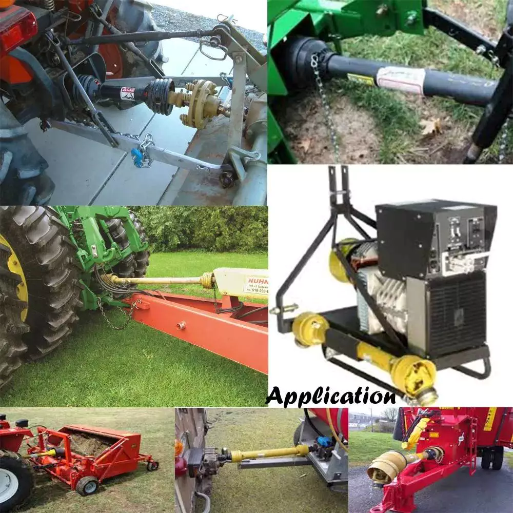
Can you provide real-world examples of farming machinery that rely on tractor PTO shafts?
Tractor power take-off (PTO) shafts are used to power a wide range of farming machinery and implements. They provide a versatile and efficient method of transmitting power from the tractor to various agricultural equipment. Here are some real-world examples of farming machinery that rely on tractor PTO shafts:
1. Rotary Mowers: Rotary mowers, commonly used for cutting grass, weeds, and vegetation, often rely on PTO shafts for power. The PTO shaft connects the mower to the tractor, enabling the blades to rotate and perform the cutting action.
2. Balers: Balers are used to compress and bale hay, straw, or other forage crops into compact bundles for storage or transportation. PTO-driven balers use the tractor's PTO shaft to power the baling mechanism, which includes the pickup, feeding system, and bale formation components.
3. Hay Rakes: Hay rakes are used to gather and arrange hay into windrows or rows for drying. PTO-driven hay rakes utilize the tractor's PTO shaft to power the rake's rotating tines, which lift and arrange the hay into neat rows.
4. Silage Choppers: Silage choppers are used to chop and process silage, which is fermented and stored animal feed. PTO-driven silage choppers rely on the tractor's PTO shaft to power the cutting mechanism, typically consisting of rotating blades or knives.
5. Seeders and Planters: Seeders and planters are used to sow seeds and plant crops in prepared soil. PTO-driven seeders and planters utilize the tractor's PTO shaft to power the seed metering and distribution mechanism, ensuring accurate seed placement and spacing.
6. Fertilizer Spreaders: Fertilizer spreaders are used to evenly distribute fertilizers, lime, or other soil amendments across fields. PTO-driven fertilizer spreaders rely on the tractor's PTO shaft to power the spreading mechanism, which may include spinning disks or augers.
7. Manure Spreaders: Manure spreaders are used to evenly distribute animal manure or compost onto fields as organic fertilizer. PTO-driven manure spreaders use the tractor's PTO shaft to power the mechanisms that agitate and spread the manure during application.
8. Post Hole Diggers: Post hole diggers are used to dig holes for fence posts, tree planting, or other applications. PTO-driven post hole diggers rely on the tractor's PTO shaft to power the auger that drills into the ground and removes soil.
9. Rotary Tillers: Rotary tillers, also known as rotavators or cultivators, are used to prepare the soil for planting by breaking up and mixing the soil. PTO-driven rotary tillers use the tractor's PTO shaft to power the rotating tines or blades that till the soil.
10. Hay Tedders: Hay tedders are used to spread and aerate hay for faster drying. PTO-driven hay tedders rely on the tractor's PTO shaft to power the rotating tines or paddles that lift and spread the hay.
These are just a few examples of farming machinery that rely on tractor PTO shafts. PTO-driven equipment is widely used in agriculture to enhance efficiency, productivity, and versatility in various farming operations.
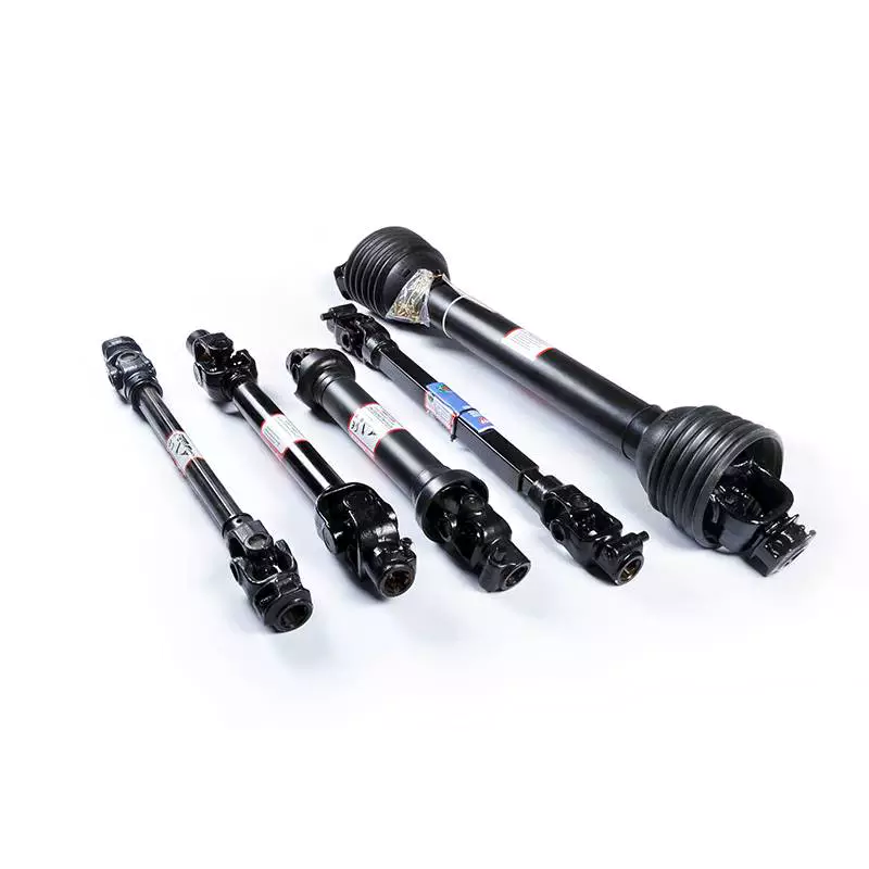
How do tractor PTO shafts accommodate variations in length and attachment methods?
Tractor PTO shafts are designed to accommodate variations in length and attachment methods to ensure compatibility with different agricultural implements. Here's a detailed explanation:
1. Telescoping Design: Many tractor PTO shafts feature a telescoping design, allowing them to be adjusted to different lengths. Telescoping PTO shafts have multiple sections that can slide in and out, enabling the shaft to be extended or retracted as needed. This feature helps accommodate variations in the distance between the tractor's PTO output shaft and the implement's input shaft.
2. Adjustable Locking Mechanisms: PTO shafts typically incorporate adjustable locking mechanisms to secure the desired length. These mechanisms may involve pins, clamps, or other locking devices that allow the operator to fix the telescoping sections at the desired position. By adjusting the locking mechanism, the PTO shaft can be set to the appropriate length based on the specific requirements of the equipment.
3. Compatible Attachment Methods: Tractor PTO shafts are designed to accommodate different attachment methods used by agricultural implements. The most common attachment method is the use of a splined connection, where the PTO shaft slides onto the implement's input shaft and is secured with a shear pin or a locking collar. The splined connection allows for a secure and reliable attachment, ensuring efficient power transfer.
4. Adapters and Couplings: In cases where the attachment methods between the tractor and the implement do not match, adapters or couplings can be used. These devices provide compatibility between different attachment methods or spline sizes. Adapters and couplings may feature different types of connections on each end to bridge the gap between the tractor's PTO shaft and the implement's input shaft, allowing for a proper and secure attachment.
5. PTO Shielding: PTO shafts also accommodate variations in PTO shielding requirements. Depending on the implement and local safety regulations, different types of shielding may be necessary. Tractor PTO shafts can be designed with detachable shielding options or offer flexibility in the positioning of safety shields to ensure compliance with safety standards.
By incorporating telescoping designs, adjustable locking mechanisms, compatible attachment methods, adapters and couplings, and considerations for PTO shielding, tractor PTO shafts can accommodate variations in length and attachment methods. These features allow for flexibility and ensure the proper fit and safe operation of the PTO shaft with various agricultural implements.
What Benefits Do Tractor PTO Shafts Offer for Various Agricultural Tasks?
Tractor power take-off (PTO) shafts offer numerous benefits for various agricultural tasks. They provide a versatile and efficient means of powering different implements used in farming operations. Here's a detailed explanation of the benefits that tractor PTO shafts offer for various agricultural tasks:
1. Versatility:
One of the key benefits of tractor PTO shafts is their versatility. PTO shafts allow farmers to connect a wide range of implements to their tractors, including rotary mowers, tillers, balers, spreaders, and more. This versatility enables farmers to perform different tasks with a single tractor, eliminating the need for multiple specialized machines. Farmers can easily switch between implements, adapting to various agricultural activities and increasing operational efficiency.
2. Increased Efficiency:
Tractor PTO shafts significantly enhance efficiency in agricultural tasks. By utilizing a single power source (the tractor's engine) to drive multiple implements, farmers can streamline their operations and save time. Instead of manually operating separate machines, farmers can leverage the power and speed control offered by the tractor's PTO shaft to efficiently perform tasks such as mowing, tilling, planting, harvesting, and more. This increased efficiency allows farmers to accomplish more work in less time, leading to improved productivity.
3. Cost Savings:
The use of tractor PTO shafts can result in cost savings for farmers. By eliminating the need for dedicated engines on each implement, farmers can avoid the expense of purchasing and maintaining multiple machines. Additionally, the versatility of PTO shafts allows farmers to invest in a smaller number of implements that can be used for multiple tasks, further reducing costs. The cost savings associated with tractor PTO shafts can contribute to improved profitability and financial sustainability for farmers.
4. Flexibility:
Tractor PTO shafts offer flexibility in agricultural operations. Farmers can easily attach and detach implements as needed, depending on the specific task at hand. This flexibility allows for rapid adaptation to changing field conditions, crop types, or seasonal requirements. Farmers can quickly switch between implements, such as switching from a mower to a seeder or from a tiller to a sprayer. The ability to utilize different implements with a single tractor provides farmers with the flexibility to optimize their operations and respond to varying agricultural demands.
5. Precise Power Control:
Tractor PTO shafts provide precise power control, allowing farmers to adjust the rotational speed and torque delivered to the implement. Different agricultural tasks require specific power requirements, and the ability to adjust the PTO speed allows farmers to optimize the performance of attached implements. For instance, certain tasks may require higher rotational speed for efficient cutting or lower speed for precise soil cultivation. The ability to control power output through the PTO shaft contributes to improved accuracy and effectiveness in various agricultural operations.
6. Standardization:
Tractor PTO shafts follow standardized connection interfaces, ensuring compatibility between tractors and implements from different manufacturers. This standardization allows farmers to easily connect implements to their tractors without compatibility issues. Farmers have a wide range of implements to choose from, and the standardized PTO shaft connection ensures seamless integration and operation. Standardization simplifies equipment selection, replacement, and compatibility concerns, enhancing the convenience and effectiveness of agricultural tasks.
7. Safety Considerations:
While not a direct benefit for agricultural tasks, tractor PTO shafts incorporate safety features to protect operators and bystanders. PTO shafts are typically equipped with protective guards or shields that cover the rotating shaft, reducing the risk of accidents or entanglement. These safety features help prevent injuries and promote safe working conditions in agricultural operations.
In summary, tractor PTO shafts offer numerous benefits for various agricultural tasks. They provide versatility, increased efficiency, cost savings, flexibility, precise power control, and standardized compatibility. By leveraging the power of the tractor's engine, PTO shafts enable farmers to efficiently power different implements, enhancing productivity and optimizing farming operations.


editor by CX 2023-09-15
China Hot selling Customized Axle CNC Hydraulic Pump Motor DC Shaft/Pto Shaft
Product Description
Our advantage:
*Specialization in CNC formulations of high precision and quality
*Independent quality control department
*Control plan and process flow sheet for each batch
*Quality control in all whole production
*Meeting demands even for very small quantities or single units
*Short delivery times
*Online orders and production progress monitoring
*Excellent price-quality ratio
*Absolute confidentiality
*Various materials (stainless steel, iron, brass, aluminum, titanium, special steels, industrial plastics)
*Manufacturing of complex components of 1 - 1000mm.
Production machine:
Inspection equipment :
Certificate:
| Material: | Carbon Steel |
|---|---|
| Load: | Drive Shaft |
| Stiffness & Flexibility: | Stiffness / Rigid Axle |
| Journal Diameter Dimensional Accuracy: | IT01-IT5 |
| Axis Shape: | Straight Shaft |
| Shaft Shape: | Real Axis |
| Customization: |
Available
| Customized Request |
|---|

Are there variations in PTO shaft designs for different types of machinery?
Yes, there are variations in PTO (Power Take-Off) shaft designs to accommodate the specific requirements of different types of machinery. PTO shafts are highly versatile and adaptable components used to transfer power from a power source, such as a tractor or engine, to driven machinery or equipment. The design variations in PTO shafts are necessary to ensure compatibility, efficiency, and safety in various applications. Here's a detailed explanation of the different PTO shaft designs for different types of machinery:
1. Standard PTO Shafts: Standard PTO shafts are the most common design and are widely used in a variety of applications. They typically consist of a solid steel shaft with a universal joint at each end. These universal joints allow for angular misalignment between the power source and the driven machinery. Standard PTO shafts are suitable for applications where the distance between the power source and the driven machinery remains relatively fixed. They are commonly used in agricultural implements, such as mowers, balers, tillers, and seeders, as well as in industrial applications.
2. Telescopic PTO Shafts: Telescopic PTO shafts feature a telescoping design that allows for length adjustment. These shafts consist of two or more concentric shafts that can slide within each other. Telescopic PTO shafts are beneficial in applications where the distance between the power source and the driven machinery varies. By adjusting the length of the shaft, operators can ensure proper power transmission without the risk of the shaft dragging on the ground or being too short to reach the equipment. Telescopic PTO shafts are commonly used in front-mounted implements, snow blowers, self-loading wagons, and other applications where the distance between the power source and the implement changes.
3. CV (Constant Velocity) PTO Shafts: CV PTO shafts incorporate Constant Velocity joints to accommodate misalignment and angular variations. These joints maintain a constant speed and torque transfer even when the driven machinery is at an angle relative to the power source. CV PTO shafts are beneficial in applications where the driven machinery requires flexibility and a wide range of movement. They are commonly used in articulated loaders, telescopic handlers, self-propelled sprayers, and other equipment that requires continuous power transmission while operating at various angles.
4. Gearbox Driven PTO Shafts: Some machinery requires specific speed or torque ratios between the power source and the driven equipment. In such cases, PTO shafts may incorporate gearbox systems. Gearbox driven PTO shafts allow for speed reduction or increase and can change the rotational direction if necessary. The gear ratios in the gearbox can be adjusted to match the speed and torque requirements of the driven machinery. These PTO shafts are commonly used in applications where the power source operates at a different speed or torque level than the equipment it drives, such as in certain industrial manufacturing processes and specialized machinery.
5. High-Torque PTO Shafts: Some heavy-duty machinery requires high torque levels for power transmission. High-torque PTO shafts are designed to handle these demanding applications. They are constructed with reinforced components, including larger diameter shafts and heavier-duty universal joints, to withstand the increased torque requirements. High-torque PTO shafts are commonly used in equipment such as wood chippers, crushers, and heavy-duty agricultural implements that require substantial power and torque for their operation.
6. Safety PTO Shafts: Safety is a crucial consideration when using PTO shafts. Safety PTO shafts incorporate mechanisms to reduce the risk of accidents and injuries. One common safety feature is the use of protective guards that cover the rotating shaft to prevent accidental contact. These guards are typically made of metal or plastic and are designed to shield the rotating components while allowing the necessary movement for power transmission. Safety PTO shafts are used in various applications where the risk of entanglement or accidental contact with the rotating shaft is high, such as in grass mowers, rotary cutters, and other equipment used in landscaping and agriculture.
These are some of the key variations in PTO shaft designs for different types of machinery. The specific design used depends on factors such as the application requirements, power source characteristics, torque levels, movement flexibility, and safety considerations. PTO shaft manufacturers offer a range of designs to ensure compatibility and efficient power transmission in diverse industries and applications.

What safety precautions should be followed when working with PTO shafts?
Working with Power Take-Off (PTO) shafts requires strict adherence to safety precautions to prevent accidents and ensure the well-being of individuals operating or working in the vicinity of the equipment. PTO shafts involve rotating machinery and can pose significant hazards if not handled properly. Here are several important safety precautions that should be followed when working with PTO shafts:
1. Familiarize Yourself with the Equipment: Prior to operating or working near a PTO shaft, it is crucial to thoroughly understand the equipment's operation, including the specific PTO shaft configuration, safety features, and any associated machinery. Read and follow the manufacturer's instructions and safety guidelines pertaining to the PTO shaft and associated equipment. Training and familiarity with the equipment are essential to ensure safe practices.
2. Wear Appropriate Personal Protective Equipment (PPE): When working with PTO shafts, individuals should wear appropriate personal protective equipment to minimize the risk of injury. This may include safety glasses, hearing protection, gloves, and sturdy footwear. PPE protects against potential hazards such as flying debris, noise, and accidental contact with rotating components.
3. Guarding and Shielding: Ensure that the PTO shaft and associated machinery are equipped with appropriate guarding and shielding. Guarding helps prevent accidental contact with rotating parts, reducing the risk of entanglement or injury. PTO shafts should have guard shields covering the rotating shaft and any exposed universal joints. Machinery driven by the PTO shaft should also have adequate guarding in place to protect against contact with moving parts.
4. Securely Fasten and Align PTO Shaft Components: Before operating or connecting the PTO shaft, ensure that all components are securely fastened and aligned. Loose or misaligned components can lead to shaft dislodgement, imbalance, and potential failure. Follow the manufacturer's guidelines for proper installation and tightening of couplings, yokes, and other connecting points. Proper alignment is crucial to prevent excessive stress, vibrations, and premature wear on the PTO shaft and associated equipment.
5. Avoid Loose Clothing and Jewelry: Loose clothing, jewelry, or other items that can become entangled in the PTO shaft or associated machinery should be avoided. Secure long hair, tuck in loose clothing, and remove or properly secure any dangling accessories. Loose items can get caught in rotating parts, leading to serious injury or entanglement hazards.
6. Do Not Modify or Remove Safety Features: PTO shafts are equipped with safety features such as guard shields, safety covers, and torque limiters for a reason. These features are designed to protect against potential hazards and should not be modified, bypassed, or removed. Altering or disabling safety features can significantly increase the risk of accidents and injury. If any safety features are damaged or not functioning correctly, they should be repaired or replaced promptly.
7. Shut Down Power Source Before Maintenance: Before performing any maintenance, repairs, or adjustments on the PTO shaft or associated machinery, ensure that the power source is completely shut down and disconnected. This includes turning off the engine, disconnecting power supply, and engaging any safety locks or mechanisms. Lockout/tagout procedures should be followed to prevent accidental energization or startup during maintenance activities.
8. Regular Maintenance and Inspection: Regular maintenance and inspection of the PTO shaft and associated equipment are vital for safe operation. Follow the manufacturer's recommended maintenance schedule and perform routine inspections to identify any signs of wear, damage, or misalignment. Lubricate universal joints as per the manufacturer's guidelines to ensure smooth operation. Promptly address any maintenance or repair needs to prevent potential hazards.
9. Training and Communication: Ensure that individuals operating or working near PTO shafts receive proper training on safe work practices, hazard identification, and emergency procedures. Promote clear communication regarding the presence and operation of PTO shafts to prevent accidental contact or interference. Establish effective communication methods, such as signals or radios, when working in teams or near noisy equipment.
10. Be Aware of Surroundings: Maintain situational awareness when working with PTO shafts. Be mindful of the location of bystanders, obstacles, and potential hazards. Ensure a clear and safe work area around the PTO shaft. Avoid distractions and focus on the task at hand to prevent accidents caused by inattention.
By following these safety precautions, individuals can minimize the risk of accidents and injuries when working with PTO shafts. Safety should always be the top priority to ensure a safe and productive work environment.

What is a PTO shaft and how is it used in agricultural and industrial equipment?
A power take-off (PTO) shaft is a mechanical component used in agricultural and industrial equipment to transfer power from a power source, such as an engine or motor, to another machine or implement. It is a driveline shaft that transmits rotational power and torque, allowing the connected equipment to perform various tasks. PTO shafts are commonly used in agricultural machinery, such as tractors, as well as in industrial equipment, including generators, pumps, and construction machinery. Here's a detailed explanation of what a PTO shaft is and how it is used:
Structure and Components: A typical PTO shaft consists of a hollow metal tube with universal joints at each end. The hollow tube allows the shaft to rotate freely, while the universal joints accommodate angular misalignments between the power source and the driven equipment. The universal joints consist of a cross-shaped yoke with needle bearings, providing flexibility and allowing the transmission of power at varying angles. Some PTO shafts may also include a telescopic section to adjust the length for different equipment setups or to accommodate varying distances between the power source and the driven machine.
Power Transfer: The primary function of a PTO shaft is to transfer power and torque from the power source to the driven equipment. The power source, typically an engine or motor, drives the PTO shaft through a mechanical connection, such as a gearbox or a clutch. As the power source rotates, it transmits rotational force to the PTO shaft. The PTO shaft, in turn, transfers this rotational power and torque to the driven equipment, enabling it to perform its intended function. The torque and rotational speed transmitted through the PTO shaft depend on the power source's characteristics and the gear ratio or clutch engagement.
Agricultural Applications: In agriculture, PTO shafts are commonly used in tractors to power various implements and attachments. The PTO shaft is connected to the tractor's power take-off, a rotating drive shaft located at the rear of the tractor. By engaging the PTO clutch, the tractor's engine power is transferred through the PTO shaft to the attached implements. Agricultural machinery, such as mowers, balers, tillers, sprayers, and grain augers, often rely on PTO shafts to receive power for their operation. The PTO shaft allows the implements to be powered directly by the tractor's engine, eliminating the need for separate power sources and increasing the versatility and efficiency of agricultural operations.
Industrial Applications: PTO shafts also find extensive use in various industrial applications. Industrial equipment, such as generators, pumps, compressors, and industrial mixers, often incorporate PTO shafts to receive power from engines or electric motors. The PTO shaft connects the power source to the driven equipment, allowing it to operate and perform its intended function. In construction machinery, PTO shafts can be found in equipment like concrete mixers, hydraulic hammers, and post hole diggers, enabling the transfer of power from the machinery's engine to the specific attachment or tool being used.
Safety Considerations: It is important to note that PTO shafts can pose safety risks if not handled properly. The rotating shaft can cause serious injuries if operators come into contact with it while it is in operation. To ensure safety, PTO shafts are often equipped with shielding or guards that cover the rotating shaft and universal joints, preventing accidental contact. It is crucial to maintain and inspect these safety features regularly to ensure their effectiveness. Additionally, operators should receive proper training on PTO shaft operation, including safe attachment and detachment procedures, as well as the use of personal protective equipment when working near PTO-driven machinery.
In summary, a PTO shaft is a mechanical component used in agricultural and industrial equipment to transmit power and torque from a power source to a driven machine or implement. It enables the direct power transfer from engines or motors to various equipment, increasing efficiency and versatility in agricultural and industrial operations. While PTO shafts offer significant benefits, operators must be aware of the associated safety considerations and take appropriate precautions to prevent accidents and injuries.
editor by CX 2023-09-14