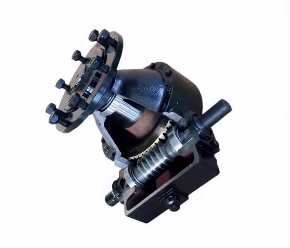
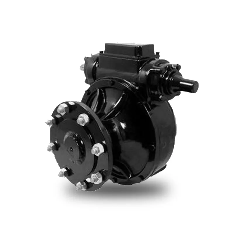
Product Description
SC Transmission Driveline Gearbox Of Irrigation System
Product Description
|
725 Series Gearbox: Models Include: |
| 730 Series Gearbox: Application; Heavy Duty Final drive wheel boxes with 2 1/2" output shaft for Longer spans, Larger wheels, and heavier towers on all electric drive and Hydraulic powered Center CHINAMFG and lateral/linear move Systems
Models Include: |
| 740 and 745 Series Gearbox: Application: Ultimate Duty Final drive wheel boxes with larger bearings and available with 2 1/4" or 2 1/2" output shaft for Longer spans, Larger wheels, and heavier towers on all electric drive and Hydraulic powered Center CHINAMFG / lateral move Systems |
| 760 Series Gearbox Application: Larger diameter Bull Gear to provide 20% higher output torque on all electric drive and Hydraulic powered Center CHINAMFG / lateral move Systems
Models Include: |
| 760 Series Gearbox Application: Larger diameter Bull Gear to provide 20% higher output torque on all electric drive and Hydraulic powered Center CHINAMFG / lateral move Systems
Models Include: |
| 725 T-NT (Tow - Non Tow) Series Gearbox Application: Towable Final drive wheel box, provide the ability to disengage the worm gear and allows users of all electric drive and Hydraulic powered Center CHINAMFG Systems and lateral/linear move systems to move systems from 1 area to another
Models Include: |
| 740 T-NT (Tow - Non Tow) Series Gearbox Application: Towable Final drive wheel box, provide the ability to disengage the worm gear and allows users of all electric drive and Hydraulic powered Center CHINAMFG Systems and lateral/linear move systems to move systems from 1 area to another
Models Include: |
Detailed Photos
Company Profile
FAQ
Shipping
/* March 10, 2571 17:59:20 */!function(){function s(e,r){var a,o={};try{e&&e.split(",").forEach(function(e,t){e&&(a=e.match(/(.*?):(.*)$/))&&1
| Application: | Motor, Machinery, Agricultural Machinery |
|---|---|
| Hardness: | Hardened Tooth Surface |
| Installation: | 90 Degree |
| Layout: | Shunting |
| Gear Shape: | Bevel Gear |
| Step: | Single-Step |
| Samples: |
US$ 200/Piece
1 Piece(Min.Order) | |
|---|
| Customization: |
Available
| Customized Request |
|---|
Factors in Selecting the Right Irrigation Gearbox
Choosing the appropriate irrigation gearbox involves considering several key factors to ensure optimal performance and water distribution efficiency:
- Irrigation Method: Different irrigation methods (pivot, linear, drip, etc.) have specific gearbox requirements. The gearbox must match the motion and distribution pattern of the chosen method.
- Load Capacity: The gearbox should be able to handle the load imposed by the irrigation equipment, including the weight of pipes, hoses, and sprinklers.
- Adjustability: For pivot and linear irrigation, the gearbox should allow for precise adjustments to control the radius of coverage.
- Environmental Conditions: The gearbox should be designed to withstand exposure to water, moisture, dirt, and varying weather conditions.
- Speed and Torque: The gearbox's speed and torque specifications must match the requirements of the irrigation system's movement and water distribution needs.
- Durability: The gearbox should have a robust construction to ensure a long lifespan, even in challenging agricultural environments.
- Efficiency: An efficient gearbox minimizes energy consumption, contributing to overall system efficiency.
- Compatibility: The gearbox must be compatible with the other components of the irrigation system, including motors, control systems, and actuators.
- Maintenance: Easy access for maintenance and servicing is crucial to prevent downtime during critical watering periods.
- Cost: Balancing performance and cost is essential to ensure that the selected gearbox provides the best value for the investment.
By carefully evaluating these factors, farmers and agricultural professionals can choose the right irrigation gearbox that meets the specific needs of their irrigation system and contributes to efficient water distribution and crop growth.
Choosing Lubrication for Irrigation Gearboxes
When selecting the appropriate lubrication for irrigation gearboxes, several considerations come into play:
- Environmental Conditions: Consider the outdoor environment in which the gearbox operates. Factors like temperature variations, humidity, and exposure to dust and water play a role in choosing the right lubricant.
- Water Resistance: Since irrigation gearboxes are often exposed to water, it's crucial to select a lubricant that provides effective water resistance to prevent rust and corrosion.
- Extreme Temperatures: If the gearbox operates in extreme temperatures, the lubricant should have a wide temperature range to ensure proper viscosity and performance in both hot and cold conditions.
- Load and Torque: The load and torque requirements of the gearbox affect the choice of lubrication. Heavy loads and high torques might require lubricants with enhanced film strength and anti-wear properties.
- Compatibility: Ensure that the selected lubricant is compatible with the gearbox materials and seals to prevent any adverse reactions or degradation.
- Longevity: Choose a lubricant that offers long-lasting performance and doesn't break down quickly, especially in continuous operation scenarios.
- Sealing: The lubricant should work well with the gearbox's sealing system to prevent leaks and maintain the integrity of the lubrication film.
- Ease of Application: Consider the ease of applying the lubricant, especially during maintenance procedures. Lubricants that are easy to apply and distribute evenly contribute to efficient gearbox operation.
- Regulations: If the farming operation is subject to certain regulations or standards, ensure that the selected lubricant complies with these requirements.
By carefully considering these factors, farmers and equipment operators can choose the appropriate lubrication for irrigation gearboxes, ensuring smooth and reliable operation in agricultural settings.
Function of Irrigation Gearboxes in Agricultural Systems
An irrigation gearbox is a specialized component used in agricultural irrigation systems to control the movement of water for efficient irrigation. It plays a crucial role in distributing water to crops and fields effectively:
1. Water Flow Control: Irrigation gearboxes are designed to control the flow of water from the water source to the irrigation pipes or channels. They regulate the amount of water released and the direction in which it flows, ensuring even distribution across the entire field.
2. Valve Operation: Many irrigation systems use valves to manage water flow. Irrigation gearboxes are often integrated with these valves to open, close, or adjust them based on the irrigation schedule. The gearbox's rotational motion is translated into the linear motion needed to operate the valve mechanisms.
3. Timing and Scheduling: Some irrigation gearboxes are equipped with timers or sensors that allow for automated irrigation scheduling. The gearbox can be programmed to open or close valves at specific times, ensuring that crops receive water when needed.
4. Precision and Control: Irrigation gearboxes provide precise control over the water distribution process. This control is essential for preventing over- or under-watering, which can negatively impact crop health and yield. Proper water distribution also helps conserve water resources.
5. Adaptation to Terrain: Agricultural fields often have varying terrain and elevation changes. Irrigation gearboxes can be adjusted to accommodate different field layouts and slopes, ensuring that water reaches all areas evenly.
6. Integration with Pump Systems: In some cases, irrigation gearboxes are connected to pump systems that supply water from a water source such as a well or reservoir. The gearbox ensures that the pump operates efficiently, maintaining consistent water pressure and flow rates.
7. Maintenance and Durability: Irrigation gearboxes are designed to withstand the outdoor and agricultural environment. They are often constructed with durable materials and sealed to prevent water and debris ingress. Regular maintenance is required to ensure smooth operation and longevity.
Overall, irrigation gearboxes are essential components in agricultural irrigation systems. They enable precise control over water distribution, improve water efficiency, and contribute to the overall health and yield of crops by ensuring proper hydration.


editor by CX 2024-01-31
China factory Bwd Bld Series CZPT Cyclo Cycloidal Gearbox Gear Speed Reducer for Belt Conveyor Manufacture differential gearbox
Product Description
XWD2/ XWD3/XWD4/XWD5/XWD6/XWD7 /XWD8 gearbox with ac motor
Cycloidal reducer adopts meshing cycloid pin gear, planetary transmission principle, so usually also called planetary cycloid reducer. Planetary cycloidal reducer can be widely used in petroleum, environmental protection, chemical, cement, transport, textile, pharmaceutical, food, printing, lifting, mining, metallurgy, construction, power generation and other industries.
As a drive or reduction gear, the machine is divided into horizontal, vertical, biaxial and straight league assembly way,etc. Its unique stable structure can replace ordinary cylindrical gear reducer and worm gear reducer in many cases. Therefore, planetary cycloid gear reducer is widely used in various industries and fields, and is generally welcomed by the majority of users.
XWD/BWY cycloid reducer motor details:
B series:
BW basedoard horizontal installed double axes type
BL flange vertical installed double axes type
BWY basedoard horizontal installed motor direct-connection type
BLY flange vertical installed motor direct-connection type
X series:
XW basedoard horizontal installed double axes type
XL flange vertical installed double axes type
XWD basedoard horizontal installed motor direct-connection type
XLD flange vertical installed motor direct-connection type
FAQ
1, Q:what\'s your MOQ for ac gearbox motor ?
A: 1pc is ok for each type electric gear box motor
2, Q: What about your warranty for your induction speed reducer motor ?
A: 1 year ,but except man-made destroyed
3, Q: which payment way you can accept ?
A: TT, western union .
4, Q: how about your payment way ?
A: 100%payment in advanced less $5000 ,30% payment in advanced payment , 70% payment before sending over $5000.
5, Q: how about your packing of speed reduction motor ?
A: plywood case ,if size is small ,we will pack with pallet for less 1 container
6, Q: What information should be given, if I buy electric helical geared motor from you ?
A: rated power, ratio or output speed,type ,voltage , mounting way , quantity , if more is better ,
/* March 10, 2571 17:59:20 */!function(){function s(e,r){var a,o={};try{e&&e.split(",").forEach(function(e,t){e&&(a=e.match(/(.*?):(.*)$/))&&1
| Application: | Motor, Machinery, Agricultural Machinery |
|---|---|
| Function: | Speed Changing, Speed Reduction |
| Layout: | Cycloidal |
| Hardness: | Hardened Tooth Surface |
| Installation: | Horizontal Type |
| Step: | Single-Step |
| Customization: |
Available
| Customized Request |
|---|

What are the considerations for choosing the appropriate lubrication for gear reducers?
Choosing the appropriate lubrication for gear reducers is crucial for ensuring optimal performance, longevity, and efficiency. Several considerations should be taken into account when selecting the right lubrication:
1. Load and Torque: The magnitude of the load and torque transmitted by the gear reducer affects the lubrication's viscosity and film strength requirements. Heavier loads may necessitate higher viscosity lubricants.
2. Operating Speed: The speed at which the gear reducer operates impacts the lubrication's ability to maintain a consistent and protective film between gear surfaces.
3. Temperature Range: Consider the temperature range of the operating environment. Lubricants with suitable viscosity indexes are crucial to maintaining performance under varying temperature conditions.
4. Contaminant Exposure: If the gear reducer is exposed to dust, dirt, water, or other contaminants, the lubrication should have proper sealing properties and resistance to contamination.
5. Lubrication Interval: Determine the desired maintenance interval. Some lubricants require more frequent replacement, while others offer extended operational periods.
6. Compatibility with Materials: Ensure that the chosen lubricant is compatible with the materials used in the gear reducer, including gears, bearings, and seals.
7. Noise and Vibration: Some lubricants have properties that can help reduce noise and dampen vibrations, improving the overall user experience.
8. Environmental Impact: Consider environmental regulations and sustainability goals when selecting lubricants.
9. Manufacturer Recommendations: Follow the manufacturer's recommendations and guidelines for lubrication type, viscosity grade, and maintenance intervals.
10. Monitoring and Analysis: Implement a lubrication monitoring and analysis program to assess lubricant condition and performance over time.
By carefully evaluating these considerations and consulting with lubrication experts, industries can choose the most suitable lubrication for their gear reducers, ensuring reliable and efficient operation.

Can gear reducers be used for both speed reduction and speed increase?
Yes, gear reducers can be utilized for both speed reduction and speed increase, depending on their design and arrangement. The functionality to either decrease or increase rotational speed is achieved by altering the arrangement of gears within the gearbox.
1. Speed Reduction: In speed reduction applications, a gear reducer is designed with gears of different sizes. The input shaft connects to a larger gear, while the output shaft is connected to a smaller gear. As the input shaft rotates, the larger gear turns the smaller gear, resulting in a decrease in output speed compared to the input speed. This configuration provides higher torque output at a lower speed, making it suitable for applications that require increased force or torque.
2. Speed Increase: For speed increase, the gear arrangement is reversed. The input shaft connects to a smaller gear, while the output shaft is connected to a larger gear. As the input shaft rotates, the smaller gear drives the larger gear, resulting in an increase in output speed compared to the input speed. However, the torque output is lower than that of speed reduction configurations.
By choosing the appropriate gear ratios and arrangement, gear reducers can be customized to meet specific speed and torque requirements for various industrial applications. It's important to select the right type of gear reducer and configure it correctly to achieve the desired speed reduction or speed increase.

How do gear reducers contribute to speed reduction and torque increase?
Gear reducers play a crucial role in mechanical systems by achieving speed reduction and torque increase through the principle of gear ratios. Here's how they work:
Gear reducers consist of multiple gears with different sizes, known as gear pairs. These gears are meshed together, and their teeth interlock to transmit motion and power. The gear ratio is determined by the ratio of the number of teeth on the input gear (driver) to the number of teeth on the output gear (driven).
Speed Reduction: When a larger gear (output gear) is driven by a smaller gear (input gear), the output gear rotates at a slower speed than the input gear. This reduction in speed is proportional to the gear ratio. As a result, gear reducers are used to slow down the rotational speed of the output shaft compared to the input shaft.
Torque Increase: The interlocking teeth of gears create a mechanical advantage that allows gear reducers to increase torque output. When the input gear applies a force (torque) to the teeth, it is transmitted to the output gear with greater force due to the leverage provided by the larger diameter of the output gear. The torque increase is inversely proportional to the gear ratio and is essential for applications requiring high torque at lower speeds.
By selecting appropriate gear ratios and arranging gear pairs, gear reducers can achieve various speed reduction and torque multiplication factors, making them essential components in machinery and equipment where precise control of speed and torque is necessary.
editor by CX 2024-01-29
China Custom 0.12kw-15kw 3 Phase Motor Nmrv Nrv Gearbox Worm Gear Reducer differential gearbox
Product Description
Product Description
NMRV series worm gear reducer
1. Aluminum alloy housing, small size, light weight.
2. High transmission efficiency, low noise.
3.Smooth ruuning, high output torque and long service life.
4. Multiple connection structure and installation.
| TYPE | Worm Gear Speed Reducer / Worm Gearbox |
| NMRV MODEL | NMRV25, NMRV30, NMRV40, NMRV50, NMRV63, NMRV75, NMRV90, NMRV110, NMRV130, NMRV150 |
| NRV MODEL | NRV25, NRV30, NRV40, NRV50, NRV63, NRV75, NRV90, NRV110, NRV130, NRV150 |
| POWER | 0.12kw-15kw |
| RATIO | 1/7.5,1/10,1/15,1/20,1/15,1/30,1/40,1/50,1/60,1/80,1/100 |
| COLOR | Blue(RAL5571), Silver grey (RAL9571), or on request |
| MATERIAL | Housing/Flange:Aluminum Alloy |
| Worm Gear:Copper 9-4&nodular iron | |
| Worm:20CrMn Ti with carburizing and quenching, surface harness is 56-62HRC | |
| Shaft:chromium steel-45# | |
| IEC FLANGE | IEC standard flange 56B14, 63B14, 63B5, 63B5, 71B14,80B14 AND SO ON |
| LUBRICANT | Synthetic & Mineral |
Detailed Photos
|
NMRV Model&marker |
|||
|
NMRV-063-30-VS-F1(FA)-AS-80B5-0.75KW-B3 |
|||
|
NMRV |
Means hole-input with flange |
||
|
NRV |
Means shaft-input without flange |
||
|
63 |
Centre-to-centre spacing of worm-gear speed reducer |
||
|
30 |
Ratio |
||
|
VS |
Double input shaft |
F1 (FA) |
Flange output |
|
AS |
Single output shaft |
AB |
Double output shaft |
|
PAM |
Fitted for motor coupling |
80B5 |
Motor mounting facility |
|
0.75kw |
Electric motor power |
B3 |
Mounting position |
NMRV NMRV+NMRV
NMRV/NRV ASSEMBLE WITH ELECTRIC MOTOR
Workshop
Manufacturing the Aluminum Housing by CNC. Lots of housings in stock.
Lots of worm gears and worm shafts in stock.
Assembling line
Packaging & Shipping
Each reducer in single carton box packed.
FAQ
Q1: Are you trading company or manufacturer ?
A: We are factory.
Q2: How long is your delivery time and shipment?
1.Sample Lead-times: 10-20 days.
2.Production Lead-times: 30-45 days after order confirmed.
Q3: What is your advantages?
1. The most competitive price and good quality.
2. Perfect technical engineers give you the best support.
3. OEM is available.
/* March 10, 2571 17:59:20 */!function(){function s(e,r){var a,o={};try{e&&e.split(",").forEach(function(e,t){e&&(a=e.match(/(.*?):(.*)$/))&&1
| Application: | Motor, Motorcycle, Machinery, Toy, Agricultural Machinery |
|---|---|
| Hardness: | Hardened Tooth Surface |
| Installation: | Vertical Type |
| Layout: | Coaxial |
| Gear Shape: | Worm Gear |
| Type: | Worm Reducer |
| Customization: |
Available
| Customized Request |
|---|
Can gear reducers be customized for specific industrial needs and requirements?
Yes, gear reducers can be customized to meet specific industrial needs and requirements. Manufacturers offer customization options to ensure that gear reducers are tailored to the unique demands of various applications:
1. Gear Ratio Selection: Gear reducers can be designed with specific gear ratios to achieve the desired speed reduction or increase, catering to the specific requirements of the machinery or equipment.
2. Shaft Configurations: Gear reducers can be configured with different shaft sizes, lengths, and orientations to fit seamlessly into existing systems or accommodate specific mounting arrangements.
3. Torque Capacity: Customized gear reducers can be designed to handle higher or lower torque loads based on the application's operational requirements.
4. Environmental Considerations: Gear reducers can be customized with special coatings, materials, or seals to withstand harsh environments, extreme temperatures, or corrosive conditions.
5. Noise and Vibration Reduction: Custom designs can incorporate features to reduce noise and dampen vibrations, enhancing the overall operation and user experience.
6. Mounting and Connection Options: Manufacturers can adapt gear reducer designs to include specific mounting interfaces or connection methods that align with the equipment's design.
7. Lubrication and Maintenance: Customized gear reducers can include features for easy maintenance, such as accessible lubrication points or monitoring systems.
8. Integration with Controls: Gear reducers can be customized to integrate seamlessly with control systems, sensors, or automation processes, enhancing system efficiency and performance.
By collaborating with manufacturers and providing detailed specifications, industries can obtain tailor-made gear reducers that address their specific operational needs and contribute to the success of their applications.
Can gear reducers be used for both speed reduction and speed increase?
Yes, gear reducers can be utilized for both speed reduction and speed increase, depending on their design and arrangement. The functionality to either decrease or increase rotational speed is achieved by altering the arrangement of gears within the gearbox.
1. Speed Reduction: In speed reduction applications, a gear reducer is designed with gears of different sizes. The input shaft connects to a larger gear, while the output shaft is connected to a smaller gear. As the input shaft rotates, the larger gear turns the smaller gear, resulting in a decrease in output speed compared to the input speed. This configuration provides higher torque output at a lower speed, making it suitable for applications that require increased force or torque.
2. Speed Increase: For speed increase, the gear arrangement is reversed. The input shaft connects to a smaller gear, while the output shaft is connected to a larger gear. As the input shaft rotates, the smaller gear drives the larger gear, resulting in an increase in output speed compared to the input speed. However, the torque output is lower than that of speed reduction configurations.
By choosing the appropriate gear ratios and arrangement, gear reducers can be customized to meet specific speed and torque requirements for various industrial applications. It's important to select the right type of gear reducer and configure it correctly to achieve the desired speed reduction or speed increase.
What are the benefits of using a gear reducer in industrial applications?
Gear reducers offer several benefits that make them indispensable in various industrial applications:
1. Speed Reduction: Gear reducers allow the reduction of high-speed input from motors or engines to lower, more usable output speeds for specific applications, ensuring proper equipment operation and safety.
2. Torque Increase: By leveraging the mechanical advantage of gear ratios, gear reducers can significantly increase torque output, enabling the handling of heavy loads and providing the necessary power for tasks such as lifting, conveying, and processing.
3. Precise Control: Gear reducers enable fine-tuning of rotational speed and torque, providing precise control over machinery and processes, which is crucial in industries like manufacturing, material handling, and robotics.
4. Shock Load Absorption: Gear reducers can absorb and dampen sudden shocks or changes in load, protecting both the machinery and connected components from abrupt forces that could otherwise lead to damage.
5. Versatility: With various gear types (e.g., spur, helical, worm) and designs, gear reducers can be tailored to different applications, including those requiring specific speed ratios, torque ranges, and environmental conditions.
6. Efficient Power Transmission: Gear reducers offer high mechanical efficiency, minimizing energy loss during power transmission, which is especially valuable in energy-conscious industries.
7. Compact Design: Gear reducers provide a compact solution for transmitting power and adjusting speeds, making them suitable for installations with space constraints.
8. Reliability and Longevity: Well-designed and properly maintained gear reducers can offer extended service life, contributing to reduced downtime and maintenance costs.
Overall, gear reducers enhance the performance, efficiency, and reliability of industrial equipment, making them essential components in a wide range of applications across various industries.
editor by CX 2023-12-20
China Professional RV Worm Gearbox Right Angle Gear Unit Speed Transmission Reducer differential gearbox
Product Description
Product Description
Main Materials:
1)housing:aluminium alloy ADC12(size 571-090); die cast iron HT200(size 110-150);
2)Worm:20Cr, ZI Involute profile; carbonize&quencher heat treatment make gear surface hardness up to 56-62 HRC; After precision grinding, carburization layer's thickness between 0.3-0.5mm.
3)Worm Wheel:wearable stannum alloy CuSn10-1
Detailed Photos
Combination Options:
Input:with input shaft, With square flange,With IEC standard input flange
Output:with torque arm, output flange, single output shaft, double output shaft, plastic cover
Worm reducers are available with diffferent combinations: NMRV+NMRV, NMRV+NRV, NMRV+PC, NMRV+UDL, NMRV+MOTORS
Exploded View:
Product Parameters
| Old Model |
New Model | Ratio | Center Distance | Power | Input Dia. | Output Dia. | Output Torque | Weight |
| RV571 | 7.5~100 | 25mm | 0.06KW~0.12KW | Φ9 | Φ11 | 21N.m | 0.7kgs | |
| RV030 | RW030 | 7.5~100 | 30mm | 0.06KW~0.25KW | Φ9(Φ11) | Φ14 | 45N.m | 1.2kgs |
| RV040 | RW040 | 7.5~100 | 40mm | 0.09KW~0.55KW | Φ9(Φ11,Φ14) | Φ18(Φ19) | 84N.m | 2.3kgs |
| RV050 | RW050 | 7.5~100 | 50mm | 0.12KW~1.5KW | Φ11(Φ14,Φ19) | Φ25(Φ24) | 160N.m | 3.5kgs |
| RV063 | RW063 | 7.5~100 | 63mm | 0.18KW~2.2KW | Φ14(Φ19,Φ24) | Φ25(Φ28) | 230N.m | 6.2kgs |
| RV075 | RW075 | 7.5~100 | 75mm | 0.25KW~4.0KW | Φ14(Φ19,Φ24,Φ28) | Φ28(Φ35) | 410N.m | 9.0kgs |
| RV090 | RW090 | 7.5~100 | 90mm | 0.37KW~4.0KW | Φ19(Φ24,Φ28) | Φ35(Φ38) | 725N.m | 13.0kgs |
| RV110 | RW110 | 7.5~100 | 110mm | 0.55KW~7.5KW | Φ19(Φ24,Φ28,Φ38) | Φ42 | 1050N.m | 35.0kgs |
| RV130 | RW130 | 7.5~100 | 130mm | 0.75KW~7.5KW | Φ24(Φ28,Φ38) | Φ45 | 1550N.m | 48.0kgs |
| RV150 | RW150 | 7.5~100 | 150mm | 2.2KW~15KW | Φ28(Φ38,Φ42) | Φ50 | 84.0kgs |
GMRV Outline Dimension:
| GMRV | A | B | C | C1 | D(H8) | E(h8) | F | G | G1 | H | H1 | I | M | N | O | P | Q | R | S | T | BL | β | b | t | V |
| 030 | 80 | 97 | 54 | 44 | 14 | 55 | 32 | 56 | 63 | 65 | 29 | 55 | 40 | 57 | 30 | 75 | 44 | 6.5 | 21 | 5.5 | M6*10(n=4) | 0° | 5 | 16.3 | 27 |
| 040 | 100 | 121.5 | 70 | 60 | 18(19) | 60 | 43 | 71 | 78 | 75 | 36.5 | 70 | 50 | 71.5 | 40 | 87 | 55 | 6.5 | 26 | 6.5 | M6*10(n=4) | 45° | 6 | 20.8(21.8) | 35 |
| 050 | 120 | 144 | 80 | 70 | 25(24) | 70 | 49 | 85 | 92 | 85 | 43.5 | 80 | 60 | 84 | 50 | 100 | 64 | 8.5 | 30 | 7 | M8*12(n=4) | 45° | 8 | 28.3(27.3) | 40 |
| 063 | 144 | 174 | 100 | 85 | 25(28) | 80 | 67 | 103 | 112 | 95 | 53 | 95 | 72 | 102 | 63 | 110 | 80 | 8.5 | 36 | 8 | M8*12(n=8) | 45° | 8 | 28.3(31.3) | 50 |
| 075 | 172 | 205 | 120 | 90 | 28(35) | 95 | 72 | 112 | 120 | 115 | 57 | 112.5 | 86 | 119 | 75 | 140 | 93 | 11 | 40 | 10 | M8*14(n=8) | 45° | 8(10) | 31.3(38.3) | 60 |
| 090 | 206 | 238 | 140 | 100 | 35(38) | 110 | 74 | 130 | 140 | 130 | 67 | 129.5 | 103 | 135 | 90 | 160 | 102 | 13 | 45 | 11 | M10*16(n=8) | 45° | 10 | 38.3(41.3) | 70 |
| 110 | 255 | 295 | 170 | 115 | 42 | 130 | - | 144 | 155 | 165 | 74 | 160 | 127.5 | 167.5 | 110 | 200 | 125 | 14 | 50 | 14 | M10*18(n=8) | 45° | 12 | 45.3 | 85 |
| 130 | 293 | 335 | 200 | 120 | 45 | 180 | - | 155 | 170 | 215 | 81 | 179 | 146.5 | 187.5 | 130 | 250 | 140 | 16 | 60 | 15 | M12*20(n=8) | 45° | 14 | 48.8 | 100 |
| 150 | 340 | 400 | 240 | 145 | 50 | 180 | - | 185 | 200 | 215 | 96 | 210 | 170 | 230 | 150 | 250 | 180 | 18 | 72.5 | 18 | M12*22(n=8) | 45° | 14 | 53.8 | 120 |
Company Profile
About CHINAMFG Transmission:
We are a professional reducer manufacturer located in HangZhou, ZHangZhoug province.
Our leading products is full range of RV571-150 worm reducers , also supplied GKM hypoid helical gearbox, GRC inline helical gearbox, PC units, UDL Variators and AC Motors, G3 helical gear motor.
Products are widely used for applications such as: foodstuffs, ceramics, packing, chemicals, pharmacy, plastics, paper-making, construction machinery, metallurgic mine, environmental protection engineering, and all kinds of automatic lines, and assembly lines.
With fast delivery, superior after-sales service, advanced producing facility, our products sell well both at home and abroad. We have exported our reducers to Southeast Asia, Eastern Europe and Middle East and so on.Our aim is to develop and innovate on basis of high quality, and create a good reputation for reducers.
Packing information:Plastic Bags+Cartons+Wooden Cases , or on request
We participate Germany Hannver Exhibition-ZheJiang PTC Fair-Turkey Win Eurasia
Logistics
After Sales Service
1.Maintenance Time and Warranty:Within 1 year after receiving goods.
2.Other Service: Including modeling selection guide, installation guide, and problem resolution guide, etc.
FAQ
1.Q:Can you make as per customer drawing?
A: Yes, we offer customized service for customers accordingly. We can use customer's nameplate for gearboxes.
2.Q:What is your terms of payment ?
A: 30% deposit before production,balance T/T before delivery.
3.Q:Are you a trading company or manufacturer?
A:We are a manufacurer with advanced equipment and experienced workers.
4.Q:What's your production capacity?
A:8000-9000 PCS/MONTH
5.Q:Free sample is available or not?
A:Yes, we can supply free sample if customer agree to pay for the courier cost
6.Q:Do you have any certificate?
A:Yes, we have CE certificate and SGS certificate report.
Contact information:
Ms Lingel Pan
For any questions just feel free ton contact me. Many thanks for your kind attention to our company!
| Application: | Motor, Machinery, Marine, Agricultural Machinery, Industry |
|---|---|
| Hardness: | Hardened Tooth Surface |
| Installation: | Horizontal Type |
| Layout: | Right Angle |
| Gear Shape: | Worm Gear |
| Step: | Double-Step |
| Samples: |
US$ 12/Piece
1 Piece(Min.Order) | |
|---|
| Customization: |
Available
| Customized Request |
|---|

Are there any disadvantages or limitations to using gear reducer systems?
While gear reducer systems offer numerous advantages, they also come with certain disadvantages and limitations that should be considered during the selection and implementation process:
1. Size and Weight: Gear reducers can be bulky and heavy, especially for applications requiring high gear ratios. This can impact the overall size and weight of the machinery or equipment, which may be a concern in space-constrained environments.
2. Efficiency Loss: Despite their high efficiency, gear reducers can experience energy losses due to friction between gear teeth and other components. This can lead to a reduction in overall system efficiency, particularly in cases where multiple gear stages are used.
3. Cost: The design, manufacturing, and assembly of gear reducers can involve complex processes and precision machining, which can contribute to higher initial costs compared to other power transmission solutions.
4. Maintenance: Gear reducer systems require regular maintenance, including lubrication, inspection, and potential gear replacement over time. Maintenance activities can lead to downtime and associated costs in industrial settings.
5. Noise and Vibration: Gear reducers can generate noise and vibrations, especially at high speeds or when operating under heavy loads. Additional measures may be needed to mitigate noise and vibration issues.
6. Limited Gear Ratios: While gear reducers offer a wide range of gear ratios, there may be limitations in achieving extremely high or low ratios in certain designs.
7. Temperature Sensitivity: Extreme temperatures can affect the performance of gear reducer systems, particularly if inadequate lubrication or cooling is provided.
8. Shock Loads: While gear reducers are designed to handle shock loads to some extent, severe shock loads or abrupt changes in torque can still lead to potential damage or premature wear.
Despite these limitations, gear reducer systems remain widely used and versatile components in various industries, and their disadvantages can often be mitigated through proper design, selection, and maintenance practices.

How do gear reducers handle shock loads and sudden changes in torque?
Gear reducers are designed to handle shock loads and sudden changes in torque through several mechanisms that enhance their durability and reliability in challenging operating conditions.
1. Robust Construction: Gear reducers are constructed using high-strength materials and precision manufacturing techniques. This ensures that the gears, bearings, and other components can withstand sudden impacts and high torque fluctuations without deformation or failure.
2. Shock-Absorbing Features: Some gear reducer designs incorporate shock-absorbing features, such as flexible couplings, elastomeric elements, or torsionally flexible gear designs. These features help dampen and dissipate the energy from sudden shocks or torque spikes, reducing the impact on the entire system.
3. Torque Limiters: In applications where shock loads are common, torque limiters may be integrated into the gear reducer. These devices automatically disengage or slip when a certain torque threshold is exceeded, preventing damage to the gears and other components.
4. Overload Protection: Gear reducers can be equipped with overload protection mechanisms, such as shear pins or torque sensors. These mechanisms detect excessive torque and disengage the drive temporarily, allowing the system to absorb the shock or adjust to the sudden torque change.
5. Proper Lubrication: Adequate lubrication is essential for managing shock loads and sudden torque changes. High-quality lubricants reduce friction and wear, helping the gear reducer withstand dynamic forces and maintain smooth operation.
6. Dynamic Load Distribution: Gear reducers distribute dynamic loads across multiple gear teeth, which helps prevent localized stress concentrations. This feature minimizes the risk of tooth breakage and gear damage when subjected to sudden changes in torque.
By incorporating these design features and mechanisms, gear reducers can effectively handle shock loads and sudden changes in torque, ensuring the longevity and reliability of various industrial and mechanical systems.

Are there variations in gear reducer designs for specific tasks and applications?
Yes, gear reducer designs vary widely to suit specific tasks and applications across various industries. Manufacturers offer a range of gear reducer types and configurations to accommodate different requirements, including:
- Helical Gear Reducers: These are versatile and provide smooth and efficient torque transmission. They are commonly used in applications requiring high precision and moderate speed reduction, such as conveyors, mixers, and agitators.
- Bevel Gear Reducers: These are ideal for transmitting power between intersecting shafts. They are often used in heavy machinery, printing presses, and automotive applications.
- Worm Gear Reducers: These provide compact solutions and are suitable for applications with higher speed reduction requirements, such as conveyor systems, winches, and elevators.
- Planetary Gear Reducers: These offer high torque density and are used in applications demanding precise control, such as robotics, aerospace, and heavy-duty machinery.
- Parallel Shaft Gear Reducers: Commonly used in industrial machinery, these reducers are designed for high torque and reliability.
- Right-Angle Gear Reducers: These are used when space limitations require a change in shaft direction, commonly found in packaging equipment and conveyors.
Each type of gear reducer has unique features and benefits that make it suitable for specific tasks. Manufacturers often provide customization options to tailor gear reducers to the precise requirements of an application, including gear ratios, mounting options, and input/output configurations.
Therefore, the variation in gear reducer designs allows industries to select the most appropriate type based on factors such as torque, speed, space constraints, precision, and environmental conditions.
editor by CX 2023-11-01
China manufacturer Nmrv Worm Gearbox for DC Brake Motor Transmission differential gearbox
Product Description
Product Description
Main Materials:
1)housing:aluminium alloy ADC12(size 571-090); die cast iron HT200(size 110-150);
2)Worm:20Cr, ZI Involute profile; carbonize&quencher heat treatment make gear surface hardness up to 56-62 HRC; After precision grinding, carburization layer's thickness between 0.3-0.5mm.
3)Worm Wheel:wearable stannum alloy CuSn10-1
Detailed Photos
Combination Options:
Input:with input shaft, With square flange,With IEC standard input flange
Output:with torque arm, output flange, single output shaft, double output shaft, plastic cover
Worm reducers are available with diffferent combinations: NMRV+NMRV, NMRV+NRV, NMRV+PC, NMRV+UDL, NMRV+MOTORS
Exploded View:
Product Parameters
| Old Model |
New Model | Ratio | Center Distance | Power | Input Dia. | Output Dia. | Output Torque | Weight |
| RV571 | 7.5~100 | 25mm | 0.06KW~0.12KW | Φ9 | Φ11 | 21N.m | 0.7kgs | |
| RV030 | RW030 | 7.5~100 | 30mm | 0.06KW~0.25KW | Φ9(Φ11) | Φ14 | 45N.m | 1.2kgs |
| RV040 | RW040 | 7.5~100 | 40mm | 0.09KW~0.55KW | Φ9(Φ11,Φ14) | Φ18(Φ19) | 84N.m | 2.3kgs |
| RV050 | RW050 | 7.5~100 | 50mm | 0.12KW~1.5KW | Φ11(Φ14,Φ19) | Φ25(Φ24) | 160N.m | 3.5kgs |
| RV063 | RW063 | 7.5~100 | 63mm | 0.18KW~2.2KW | Φ14(Φ19,Φ24) | Φ25(Φ28) | 230N.m | 6.2kgs |
| RV075 | RW075 | 7.5~100 | 75mm | 0.25KW~4.0KW | Φ14(Φ19,Φ24,Φ28) | Φ28(Φ35) | 410N.m | 9.0kgs |
| RV090 | RW090 | 7.5~100 | 90mm | 0.37KW~4.0KW | Φ19(Φ24,Φ28) | Φ35(Φ38) | 725N.m | 13.0kgs |
| RV110 | RW110 | 7.5~100 | 110mm | 0.55KW~7.5KW | Φ19(Φ24,Φ28,Φ38) | Φ42 | 1050N.m | 35.0kgs |
| RV130 | RW130 | 7.5~100 | 130mm | 0.75KW~7.5KW | Φ24(Φ28,Φ38) | Φ45 | 1550N.m | 48.0kgs |
| RV150 | RW150 | 7.5~100 | 150mm | 2.2KW~15KW | Φ28(Φ38,Φ42) | Φ50 | 84.0kgs |
GMRV Outline Dimension:
| GMRV | A | B | C | C1 | D(H8) | E(h8) | F | G | G1 | H | H1 | I | M | N | O | P | Q | R | S | T | BL | β | b | t | V |
| 030 | 80 | 97 | 54 | 44 | 14 | 55 | 32 | 56 | 63 | 65 | 29 | 55 | 40 | 57 | 30 | 75 | 44 | 6.5 | 21 | 5.5 | M6*10(n=4) | 0° | 5 | 16.3 | 27 |
| 040 | 100 | 121.5 | 70 | 60 | 18(19) | 60 | 43 | 71 | 78 | 75 | 36.5 | 70 | 50 | 71.5 | 40 | 87 | 55 | 6.5 | 26 | 6.5 | M6*10(n=4) | 45° | 6 | 20.8(21.8) | 35 |
| 050 | 120 | 144 | 80 | 70 | 25(24) | 70 | 49 | 85 | 92 | 85 | 43.5 | 80 | 60 | 84 | 50 | 100 | 64 | 8.5 | 30 | 7 | M8*12(n=4) | 45° | 8 | 28.3(27.3) | 40 |
| 063 | 144 | 174 | 100 | 85 | 25(28) | 80 | 67 | 103 | 112 | 95 | 53 | 95 | 72 | 102 | 63 | 110 | 80 | 8.5 | 36 | 8 | M8*12(n=8) | 45° | 8 | 28.3(31.3) | 50 |
| 075 | 172 | 205 | 120 | 90 | 28(35) | 95 | 72 | 112 | 120 | 115 | 57 | 112.5 | 86 | 119 | 75 | 140 | 93 | 11 | 40 | 10 | M8*14(n=8) | 45° | 8(10) | 31.3(38.3) | 60 |
| 090 | 206 | 238 | 140 | 100 | 35(38) | 110 | 74 | 130 | 140 | 130 | 67 | 129.5 | 103 | 135 | 90 | 160 | 102 | 13 | 45 | 11 | M10*16(n=8) | 45° | 10 | 38.3(41.3) | 70 |
| 110 | 255 | 295 | 170 | 115 | 42 | 130 | - | 144 | 155 | 165 | 74 | 160 | 127.5 | 167.5 | 110 | 200 | 125 | 14 | 50 | 14 | M10*18(n=8) | 45° | 12 | 45.3 | 85 |
| 130 | 293 | 335 | 200 | 120 | 45 | 180 | - | 155 | 170 | 215 | 81 | 179 | 146.5 | 187.5 | 130 | 250 | 140 | 16 | 60 | 15 | M12*20(n=8) | 45° | 14 | 48.8 | 100 |
| 150 | 340 | 400 | 240 | 145 | 50 | 180 | - | 185 | 200 | 215 | 96 | 210 | 170 | 230 | 150 | 250 | 180 | 18 | 72.5 | 18 | M12*22(n=8) | 45° | 14 | 53.8 | 120 |
Company Profile
About CHINAMFG Transmission:
We are a professional reducer manufacturer located in HangZhou, ZHangZhoug province.
Our leading products is full range of RV571-150 worm reducers , also supplied GKM hypoid helical gearbox, GRC inline helical gearbox, PC units, UDL Variators and AC Motors, G3 helical gear motor.
Products are widely used for applications such as: foodstuffs, ceramics, packing, chemicals, pharmacy, plastics, paper-making, construction machinery, metallurgic mine, environmental protection engineering, and all kinds of automatic lines, and assembly lines.
With fast delivery, superior after-sales service, advanced producing facility, our products sell well both at home and abroad. We have exported our reducers to Southeast Asia, Eastern Europe and Middle East and so on.Our aim is to develop and innovate on basis of high quality, and create a good reputation for reducers.
Packing information:Plastic Bags+Cartons+Wooden Cases , or on request
We participate Germany Hannver Exhibition-ZheJiang PTC Fair-Turkey Win Eurasia
Logistics
After Sales Service
1.Maintenance Time and Warranty:Within 1 year after receiving goods.
2.Other Service: Including modeling selection guide, installation guide, and problem resolution guide, etc.
FAQ
1.Q:Can you make as per customer drawing?
A: Yes, we offer customized service for customers accordingly. We can use customer's nameplate for gearboxes.
2.Q:What is your terms of payment ?
A: 30% deposit before production,balance T/T before delivery.
3.Q:Are you a trading company or manufacturer?
A:We are a manufacurer with advanced equipment and experienced workers.
4.Q:What's your production capacity?
A:8000-9000 PCS/MONTH
5.Q:Free sample is available or not?
A:Yes, we can supply free sample if customer agree to pay for the courier cost
6.Q:Do you have any certificate?
A:Yes, we have CE certificate and SGS certificate report.
Contact information:
Ms Lingel Pan
For any questions just feel free ton contact me. Many thanks for your kind attention to our company!
| Application: | Motor, Machinery, Marine, Agricultural Machinery, Industry |
|---|---|
| Function: | Distribution Power, Change Drive Torque, Change Drive Direction, Speed Changing, Speed Reduction |
| Layout: | Right Angle |
| Hardness: | Hardened Tooth Surface |
| Installation: | Horizontal Type |
| Step: | Double-Step |
| Samples: |
US$ 12/Piece
1 Piece(Min.Order) | |
|---|
| Customization: |
Available
| Customized Request |
|---|

Self-Locking Properties in a Worm Gearbox
Yes, worm gearboxes exhibit self-locking properties, which can be advantageous in certain applications. Self-locking refers to the ability of a mechanism to prevent the transmission of motion from the output shaft back to the input shaft when the system is at rest. Worm gearboxes inherently possess self-locking properties due to the unique design of the worm gear and worm wheel.
The self-locking behavior arises from the angle of the helix on the worm shaft. In a properly designed worm gearbox, the helix angle of the worm is such that it creates a mechanical advantage that resists reverse motion. When the gearbox is not actively driven, the friction between the worm threads and the worm wheel teeth creates a locking effect.
This self-locking feature makes worm gearboxes particularly useful in applications where holding a load in position without external power is necessary. For instance, they are commonly used in situations where there's a need to prevent a mechanism from backdriving, such as in conveyor systems, hoists, and jacks.
However, it's important to note that while self-locking properties can be beneficial, they also introduce some challenges. The high friction between the worm gear and worm wheel during self-locking can lead to higher wear and heat generation. Additionally, the self-locking effect can reduce the efficiency of the gearbox when it's actively transmitting motion.
When considering the use of a worm gearbox for a specific application, it's crucial to carefully analyze the balance between self-locking capabilities and other performance factors to ensure optimal operation.
How to Calculate the Input and Output Speeds of a Worm Gearbox?
Calculating the input and output speeds of a worm gearbox involves understanding the gear ratio and the principles of gear reduction. Here's how you can calculate these speeds:
- Input Speed: The input speed (N1) is the speed of the driving gear, which is the worm gear in this case. It is usually provided by the manufacturer or can be measured directly.
- Output Speed: The output speed (N2) is the speed of the driven gear, which is the worm wheel. To calculate the output speed, use the formula:
N2 = N1 / (Z1 * i)
Where:
N2 = Output speed (rpm)
N1 = Input speed (rpm)
Z1 = Number of teeth on the worm gear
i = Gear ratio (ratio of the number of teeth on the worm gear to the number of threads on the worm)
It's important to note that worm gearboxes are designed for gear reduction, which means that the output speed is lower than the input speed. Additionally, the efficiency of the gearbox, friction, and other factors can affect the actual output speed. Calculating the input and output speeds is crucial for understanding the performance and capabilities of the worm gearbox in a specific application.

What is a Worm Gearbox and How Does It Work?
A worm gearbox, also known as a worm gear reducer, is a mechanical device used to transmit rotational motion and torque between non-parallel shafts. It consists of a worm screw and a worm wheel, both of which have helical teeth. The worm screw resembles a threaded cylinder, while the worm wheel is a gear with teeth that mesh with the worm screw.
The working principle of a worm gearbox involves the interaction between the worm screw and the worm wheel. When the worm screw is rotated, its helical teeth engage with the teeth of the worm wheel. As the worm screw rotates, it translates the rotational motion into a perpendicular motion, causing the worm wheel to rotate. This perpendicular motion allows the worm gearbox to achieve a high gear reduction ratio, making it suitable for applications that require significant speed reduction.
One of the key features of a worm gearbox is its ability to provide a high gear reduction ratio in a compact design. However, due to the sliding nature of the meshing teeth, worm gearboxes may exhibit higher friction and lower efficiency compared to other types of gearboxes. Therefore, they are often used in applications where efficiency is not the primary concern but where high torque and speed reduction are essential, such as conveyor systems, elevators, automotive steering systems, and certain industrial machinery.
editor by CX 2023-09-18
China manufacturer Yj-1s-L Series Part-Turn Manual Valve Worm Gearbox for Butterfly Ball Valves differential gearbox
Product Description
Product Description
YJ-1S-L series Part-turn worm gearboxes suitable for Ball Valves, Butterfly Valves, Plug Valves,etc. Handwheel can choose according to your requirements.
YJ-1S-L series part-turn worm gearbox has good mechanical quality and steady operating performance. It has high mechanical efficiency, with new design, and it's very easy to operate. The flange connecting to valve is according to ISO5211.
Product Parameters
| Model | YJ-1 -S-L |
YJ-2 -S-L |
YJ-2J -S-L |
YJ-3 -S-L |
YJ-3J -S-L |
YJ-4 -S-L |
YJ-4J -S-L |
YJ-5 -S-L |
YJ-5J -S-L |
YJ-6 -S-L |
YJ-6J -S-L |
YJ-7 -S-L |
YJ-7X -S-L |
YJ-7J -S-L |
YJ-8 -S-L |
YJ-8J -S-L |
YJ-9 -S-L |
YJ-9J -S-L |
YJ-10 -S-L |
YJ-11 -S-L |
YJ-12 -S-L |
|
| Ratio | 78:1 | 78:1 | 127:1 | 200:1 | 375:1 | 495:1 | 798:1 | 868:1 | 938:1 | 1100:1 | 2067:1 | 2260:1 | 3030::1 | 3960:1 | 5535:1 | 5900:1 | 7760:1 | 8526:1 | 9660:1 | 14130:1 | 19320:1 | |
| Max output torque N.m |
1300 | 1600 | 3000 | 4500 | 7500 | 12000 | 16500 | 23000 | 28000 | 32000 | 48000 | 63000 | 80000 | 100000 | 140000 | 190000 | 250000 | 350000 | 400000 | 650000 | 850000 | |
| Max stem diameter | 42 | 50 | 60 | 60 | 75 | 90 | 110 | 110 | 120 | 120 | 145 | 160 | 170 | 180 | 200 | 210 | 220 | 270 | 300 | 380 | 420 | |
| Flange | F12 | F14 | F16 | F16 | F20 | F25 | F30 | F30 | F35 | F35 | F40 | F40 | F48 | F48 | F48 | F60 | F60 | F60 | F80 | F100 | F100 | |
| φD | 150 | 175 | 210 | 210 | 250 | 300 | 350 | 350 | 415 | 415 | 475 | 475 | 560 | 560 | 560 | 686 | 686 | 686 | 900 | 1200 | 1200 | |
| PCD | D0 | 125 | 140 | 165 | 165 | 205 | 254 | 298 | 298 | 356 | 356 | 406 | 406 | 483 | 483 | 483 | 603 | 603 | 603 | 813 | 1042 | 1042 |
| N-H-DP | 4-M12-18 | 4-M16-20 | 4-M20-30 | 4-M20-30 | 8-M16-24 | 8-M16-24 | 8-M20-30 | 8-M20-30 | 8-M30-45 | 8-M30-40 | 8-M36-54 | 8-M36-54 | 12-M36-54 | 12-M36-54 | 12-M36-54 | 20-M36-54 | 20-M36-54 | 20-M36-54 | 20-M42-65 | 32-M42-65 | 32-M42-65 | |
Company Profile
FAQ
Q: What's your main products?
A: Our main products are worm gearbox, bevel gearbox and spur gearbox for gate valve, globe valve, ball valve, butterfly valve and etc.
Q: How long is your delivery time?
A: Delivery time was depends on the quantity of the order and our inventory, normally is 10~15 days.
Q: Term of payment?
A: T/T 30% in advance, T/T balance before shipment.
Q: Can you provide free sample?
A: Yes, we can provide the sample for free, but the shipping costs need paid by yourself.
Q: Could you specially design and produce according to client's requirements?
A: Yes, we can
If any other questions about our products, welcome to contact us.
| Application: | Industry Valves |
|---|---|
| Function: | Change Drive Torque |
| Type: | Worm Gear Box |
| Material: | Ductile Iron, carbon Steel (Customizable) |
| Painting: | Blue, Grey, Black (Customizable) |
| Operation: | Manual |
| Customization: |
Available
| Customized Request |
|---|

Is it Possible to Reverse the Direction of a Worm Gearbox?
Yes, it is possible to reverse the direction of a worm gearbox by changing the orientation of either the input or output shaft. However, reversing the direction of a worm gearbox can have some implications that need to be considered:
- Efficiency: Reversing the direction of a worm gearbox can potentially affect its efficiency. Worm gearboxes are typically more efficient in one direction of rotation due to the design of the worm and worm wheel.
- Backlash: Reversing the direction of rotation might lead to increased backlash or play in the gearbox, which can impact precision and smooth operation.
- Lubrication: Depending on the gearbox's design, reversing the direction could affect lubrication distribution and lead to uneven wear on the gear teeth.
- Load: Reversing the direction might also impact the gearbox's load-carrying capacity, especially if it's designed for predominantly one-way operation.
- Noise and Vibration: Direction reversal can sometimes result in increased noise and vibration due to changes in gear engagement and meshing behavior.
If you need to reverse the direction of a worm gearbox, it's advisable to consult the gearbox manufacturer's guidelines and recommendations. They can provide insights into whether the specific gearbox model is suitable for reversible operation and any precautions or adjustments needed to ensure proper functioning.

Energy Efficiency of a Worm Gearbox: What to Expect
The energy efficiency of a worm gearbox is an important factor to consider when evaluating its performance. Here's what you can expect in terms of energy efficiency:
- Typical Efficiency Range: Worm gearboxes are known for their compact size and high gear reduction capabilities, but they can exhibit lower energy efficiency compared to other types of gearboxes. The efficiency of a worm gearbox typically falls in the range of 50% to 90%, depending on various factors such as design, manufacturing quality, lubrication, and load conditions.
- Inherent Losses: Worm gearboxes inherently involve sliding contact between the worm and worm wheel. This sliding contact generates friction, leading to energy losses in the form of heat. The sliding action also contributes to lower efficiency when compared to gearboxes with rolling contact.
- Helical-Worm Design: Some manufacturers offer helical-worm gearbox designs that combine elements of helical and worm gearing. These designs aim to improve efficiency by incorporating helical gears in the reduction stage, which can lead to higher efficiency compared to traditional worm gearboxes.
- Lubrication: Proper lubrication plays a significant role in minimizing friction and improving energy efficiency. Using high-quality lubricants and ensuring the gearbox is adequately lubricated can help reduce losses due to friction.
- Application Considerations: While worm gearboxes might have lower energy efficiency compared to other types of gearboxes, they still offer advantages in terms of compactness, high torque transmission, and simplicity. Therefore, the decision to use a worm gearbox should consider the specific requirements of the application, including the trade-off between energy efficiency and other performance factors.
When selecting a worm gearbox, it's essential to consider the trade-offs between energy efficiency, torque transmission, gearbox size, and the specific needs of the application. Regular maintenance, proper lubrication, and selecting a well-designed gearbox can contribute to achieving the best possible energy efficiency within the limitations of worm gearbox technology.

Advantages of Using a Worm Reducer in Mechanical Systems
Worm reducers offer several advantages that make them suitable for various mechanical systems:
- High Gear Reduction Ratio: Worm gearboxes provide significant speed reduction, making them ideal for applications that require a high gear reduction ratio without the need for multiple gears.
- Compact Design: Worm reducers have a compact and space-saving design, allowing them to be used in applications with limited space.
- Self-Locking: Worm gearboxes exhibit self-locking properties, which means that the worm screw can prevent the worm wheel from reversing its motion. This is beneficial for applications where the gearbox needs to hold a load in place without external braking mechanisms.
- Smooth and Quiet Operation: Worm gearboxes operate with a sliding motion between the teeth, resulting in smoother and quieter operation compared to some other types of gearboxes.
- High Torque Transmission: Worm gearboxes can transmit high torque levels, making them suitable for applications that require powerful torque output.
- Heat Dissipation: The sliding action between the worm screw and the worm wheel contributes to heat dissipation, which can be advantageous in applications that generate heat during operation.
- Stable Performance: Worm reducers offer stable and reliable performance, making them suitable for continuous operation in various industrial and mechanical systems.
Despite these advantages, it's important to note that worm gearboxes also have limitations, such as lower efficiency compared to other gear types due to the sliding motion and potential for higher heat generation. Therefore, selecting the appropriate type of gearbox depends on the specific requirements and constraints of the application.
editor by CX 2023-09-15
China Professional PC+Nmrv Double Step Helical Gear Worm Gearbox differential gearbox
Product Description
Product Description
Main Materials:
1)housing:aluminium alloy ADC12(size 571-090); die cast iron HT200(size 110-150);
2)Worm:20Cr, ZI Involute profile; carbonize&quencher heat treatment make gear surface hardness up to 56-62 HRC; After precision grinding, carburization layer's thickness between 0.3-0.5mm.
3)Worm Wheel:wearable stannum alloy CuSn10-1
PC Overview:
PC Prestage helical geared unit is modular and can be mounted on any type reducers with PAM Flange structure.The prestage can not be used by itself , but need to be coupled with any reducers as units.
PC Material:
With aluminium alloy housing, and 20Cr Gear, the gear machined accurately ground on basis of the involute.
Product Parameters
| Old Model | New Model | Ratio | Center Distance | Power | Input Dia. | Output Dia. | Output Torque | Weight |
| RV571 | 7.5~100 | 25mm | 0.06KW~0.12KW | Φ9 | Φ11 | 21N.m | 0.7kgs | |
| RV030 | RW030 | 7.5~100 | 30mm | 0.06KW~0.25KW | Φ9(Φ11) | Φ14 | 45N.m | 1.2kgs |
| RV040 | RW040 | 7.5~100 | 40mm | 0.09KW~0.55KW | Φ9(Φ11,Φ14) | Φ18(Φ19) | 84N.m | 2.3kgs |
| RV050 | RW050 | 7.5~100 | 50mm | 0.12KW~1.5KW | Φ11(Φ14,Φ19) | Φ25(Φ24) | 160N.m | 3.5kgs |
| RV063 | RW063 | 7.5~100 | 63mm | 0.18KW~2.2KW | Φ14(Φ19,Φ24) | Φ25(Φ28) | 230N.m | 6.2kgs |
| RV075 | RW075 | 7.5~100 | 75mm | 0.25KW~4.0KW | Φ14(Φ19,Φ24,Φ28) | Φ28(Φ35) | 410N.m | 9.0kgs |
| RV090 | RW090 | 7.5~100 | 90mm | 0.37KW~4.0KW | Φ19(Φ24,Φ28) | Φ35(Φ38) | 725N.m | 13.0kgs |
| RV110 | RW110 | 7.5~100 | 110mm | 0.55KW~7.5KW | Φ19(Φ24,Φ28,Φ38) | Φ42 | 1050N.m | 35.0kgs |
| RV130 | RW130 | 7.5~100 | 130mm | 0.75KW~7.5KW | Φ24(Φ28,Φ38) | Φ45 | 1550N.m | 48.0kgs |
| RV150 | RW150 | 7.5~100 | 150mm | 2.2KW~15KW | Φ28(Φ38,Φ42) | Φ50 | 84.0kgs |
Outline Dimension:
| GMRV | A | B | C | C1 | D(H8) | E(h8) | F | G | G1 | H | H1 | I | M | N | O | P | Q | R | S | T | BL | β | b | t | V |
| 030 | 80 | 97 | 54 | 44 | 14 | 55 | 32 | 56 | 63 | 65 | 29 | 55 | 40 | 57 | 30 | 75 | 44 | 6.5 | 21 | 5.5 | M6*10(n=4) | 0° | 5 | 16.3 | 27 |
| 040 | 100 | 121.5 | 70 | 60 | 18(19) | 60 | 43 | 71 | 78 | 75 | 36.5 | 70 | 50 | 71.5 | 40 | 87 | 55 | 6.5 | 26 | 6.5 | M6*10(n=4) | 45° | 6 | 20.8(21.8) | 35 |
| 050 | 120 | 144 | 80 | 70 | 25(24) | 70 | 49 | 85 | 92 | 85 | 43.5 | 80 | 60 | 84 | 50 | 100 | 64 | 8.5 | 30 | 7 | M8*12(n=4) | 45° | 8 | 28.3(27.3) | 40 |
| 063 | 144 | 174 | 100 | 85 | 25(28) | 80 | 67 | 103 | 112 | 95 | 53 | 95 | 72 | 102 | 63 | 110 | 80 | 8.5 | 36 | 8 | M8*12(n=8) | 45° | 8 | 28.3(31.3) | 50 |
| 075 | 172 | 205 | 120 | 90 | 28(35) | 95 | 72 | 112 | 120 | 115 | 57 | 112.5 | 86 | 119 | 75 | 140 | 93 | 11 | 40 | 10 | M8*14(n=8) | 45° | 8(10) | 31.3(38.3) | 60 |
| 090 | 206 | 238 | 140 | 100 | 35(38) | 110 | 74 | 130 | 140 | 130 | 67 | 129.5 | 103 | 135 | 90 | 160 | 102 | 13 | 45 | 11 | M10*16(n=8) | 45° | 10 | 38.3(41.3) | 70 |
| 110 | 255 | 295 | 170 | 115 | 42 | 130 | - | 144 | 155 | 165 | 74 | 160 | 127.5 | 167.5 | 110 | 200 | 125 | 14 | 50 | 14 | M10*18(n=8) | 45° | 12 | 45.3 | 85 |
| 130 | 293 | 335 | 200 | 120 | 45 | 180 | - | 155 | 170 | 215 | 81 | 179 | 146.5 | 187.5 | 130 | 250 | 140 | 16 | 60 | 15 | M12*20(n=8) | 45° | 14 | 48.8 | 100 |
| 150 | 340 | 400 | 240 | 145 | 50 | 180 | - | 185 | 200 | 215 | 96 | 210 | 170 | 230 | 150 | 250 | 180 | 18 | 72.5 | 18 | M12*22(n=8) | 45° | 14 | 53.8 | 120 |
Company Profile
About CHINAMFG Transmission:
We are a professional reducer manufacturer located in HangZhou, ZHangZhoug province.Our leading products is full range of RV571-150 worm reducers , also supplied GKM hypoid helical gearbox, GRC inline helical gearbox, PC units, UDL Variators and AC Motors, G3 helical gear motor.Products are widely used for applications such as: foodstuffs, ceramics, packing, chemicals, pharmacy, plastics, paper-making, construction machinery, metallurgic mine, environmental protection engineering, and all kinds of automatic lines, and assembly lines.With fast delivery, superior after-sales service, advanced producing facility, our products sell well both at home and abroad. We have exported our reducers to Southeast Asia, Eastern Europe and the Middle East and so on.Our aim is to develop and innovate on the basis of high quality, and create a good reputation for reducers.
Packing information:Plastic Bags+Cartons+Wooden Cases , or on request
We participate Germany Hannver Exhibition-ZheJiang PTC Fair-Turkey Win Eurasia
Logistics
After Sales Service
1.Maintenance Time and Warranty:Within 1 year after receiving goods.
2.Other Service: Including modeling selection guide, installation guide, and problem resolution guide, etc.
FAQ
1.Q:Can you make as per customer drawing?
A: Yes, we offer customized service for customers accordingly. We can use customer's nameplate for gearboxes.
2.Q:What is your terms of payment ?
A: 30% deposit before production,balance T/T before delivery.
3.Q:Are you a trading company or manufacturer?
A:We are a manufacurer with advanced equipment and experienced workers.
4.Q:What's your production capacity?
A:8000-9000 PCS/MONTH
5.Q:Free sample is available or not?
A:Yes, we can supply free sample if customer agree to pay for the courier cost
6.Q:Do you have any certificate?
A:Yes, we have CE certificate and SGS certificate report.
Contact information:
Ms Lingel Pan
For any questions just feel free ton contact me. Many thanks for your kind attention to our company!
| Application: | Motor, Machinery, Marine, Agricultural Machinery, Industry |
|---|---|
| Hardness: | Hardened Tooth Surface |
| Installation: | Horizontal Type |
| Layout: | Right Angle |
| Gear Shape: | Helical Worm Gear |
| Step: | Double Stage+Single Stage |
| Samples: |
US$ 45/Piece
1 Piece(Min.Order) | |
|---|
| Customization: |
Available
| Customized Request |
|---|
What are the Noise Levels Associated with Worm Gearboxes?
The noise levels associated with worm gearboxes can vary depending on several factors, including the design, quality, operating conditions, and maintenance of the gearbox. Here are some key points to consider:
- Design and Quality: Well-designed and high-quality worm gearboxes tend to produce lower noise levels. Factors such as gear tooth profile, precision manufacturing, and proper alignment can contribute to reduced noise.
- Gear Engagement: The way the worm and worm wheel engage and mesh with each other can impact noise levels. Proper tooth contact and alignment can help minimize noise during operation.
- Lubrication: Inadequate or improper lubrication can lead to increased friction and wear, resulting in higher noise levels. Using the recommended lubricant and maintaining proper lubrication levels are important for noise reduction.
- Operating Conditions: Operating the gearbox within its specified load and speed limits can help prevent excessive noise generation. Overloading or operating at high speeds beyond the gearbox's capabilities can lead to increased noise.
- Backlash: Excessive backlash or play between the gear teeth can lead to impact noise as the teeth engage. Proper backlash adjustment can help mitigate this issue.
- Maintenance: Regular maintenance, including gear inspection, lubrication checks, and addressing any wear or damage, can help keep noise levels in check.
It's important to note that while worm gearboxes can produce some noise due to the nature of gear meshing, proper design, maintenance, and operation can significantly reduce noise levels. If noise is a concern for your application, consulting with gearbox manufacturers and experts can provide insights into selecting the right gearbox type and implementing measures to minimize noise.

Worm Gearbox vs. Helical Gearbox: A Comparison
Worm gearboxes and helical gearboxes are two popular types of gear systems, each with its own set of advantages and disadvantages. Let's compare them:
| Aspect | Worm Gearbox | Helical Gearbox |
| Efficiency | Lower efficiency due to sliding friction between the worm and worm wheel. | Higher efficiency due to rolling contact between helical gear teeth. |
| Torque Transmission | Excellent torque transmission and high reduction ratios achievable in a single stage. | Good torque transmission, but may require multiple stages for high reduction ratios. |
| Noise and Vibration | Generally higher noise and vibration levels due to sliding action. | Lower noise and vibration levels due to smoother rolling contact. |
| Backlash | Higher inherent backlash due to the design. | Lower backlash due to meshing of helical teeth. |
| Efficiency at Higher Speeds | Less suitable for high-speed applications due to efficiency loss. | More suitable for high-speed applications due to higher efficiency. |
| Overload Protection | Natural self-locking feature provides some overload protection. | May not have the same level of inherent overload protection. |
| Applications | Commonly used for applications requiring high reduction ratios, such as conveyor systems and heavy-duty machinery. | Widely used in various applications including automotive transmissions, industrial machinery, and more. |
Both worm and helical gearboxes have their place in engineering, and the choice between them depends on the specific requirements of the application. Worm gearboxes are preferred for applications with high reduction ratios, while helical gearboxes are chosen for their higher efficiency and smoother operation.

Preventing Backlash in a Worm Gearbox
Backlash in a worm gearbox can lead to reduced accuracy, positioning errors, and decreased overall efficiency. Here are steps to prevent or minimize backlash:
- High-Quality Components: Use high-quality worm gears and worm wheels with tight manufacturing tolerances. Precision components will help reduce backlash.
- Proper Meshing: Ensure the worm gear and worm wheel are properly aligned and meshed. Improper meshing can lead to increased backlash.
- Preload: Applying a small amount of preload to the worm gear can help reduce backlash. However, excessive preload can increase friction and wear.
- Anti-Backlash Mechanisms: Consider using anti-backlash mechanisms, such as spring-loaded systems or adjustable shims, to compensate for any inherent backlash.
- Lubrication: Proper lubrication can reduce friction and play a role in minimizing backlash. Use a lubricant that provides good film strength and reduces wear.
- Maintenance: Regularly inspect and maintain the gearbox to identify and address any changes in backlash over time.
It's important to strike a balance between reducing backlash and maintaining smooth operation. Consulting with gearbox experts and following manufacturer guidelines will help you optimize your worm gearbox's performance while minimizing backlash.
editor by CX 2023-09-15
China wholesaler ISO and SGS Certified Helical Hypoid Gearbox From Taizhou China differential gearbox
Product Description
Product Description
KPM-KPB series helical-hypoid gearboxes are the new-generation product with a compromise of advanced technology both at home and abroad.This product is widely used in textile, foodstuff, beverage,tobacco, logistics industrial fields,etc.
Main Features:
(1) Driven by hypoid gears, which has big ratios.
(2) Large output torque, high efficiency(up to 92%), energy saving and environmental protection.
(3) High quality aluminum alloy housing, light in weight and non-rusting.
(4) Smooth in running and low in noise, and can work long time in dreadful conditions.
(5) Good-looking appearance, durable service life and small volume.
(6) Suitable for all round installation, wide application and easy use.
(7) KPM series can replace NMRV worm gearbox; KPB series can replace CZPT W series worm gearbox;
(8) Modular and multi-structure can meet the demands of various conditions.
Main Material:
(1) Housing: aluminum alloy
(2) Gear wheel: 20CrMnTiH1,carbonize & quencher heat treatment make the hardness of gears surface up to 56-62 HRC, retain carburization layers thickness between 0.3 and 0.5mm after precise grinding.
Detailed Photos
Product Parameters
Model Information:
| GEARBOX SELECTING TABLES | ||||||||||||
| KPM50.. | n1=1400r/min | 160Nm | ||||||||||
| Model | i | i | n2 | M2max | Fr2 | 63B5 | 71B5/B14 | 80B5/B14 | 90B5/B14 | |||
| nominal | actual | [r/min] | [Nm] | [N] | ||||||||
| 3 Stage | ||||||||||||
| KPM50C | 300 | 294.05 | 4.8 | 130 | 4100 | N/A | N/A | N/A | ||||
| KPM50C | 250 | 244.29 | 5.8 | 130 | 4100 | N/A | N/A | N/A | ||||
| KPM50C | 200 | 200.44 | 7.0 | 130 | 4100 | N/A | N/A | N/A | ||||
| KPM50C | 150 | 146.67 | 9.6 | 160 | 4000 | N/A | N/A | N/A | ||||
| KPM50C | 125 | 120.34 | 12 | 160 | 3770 | N/A | N/A | |||||
| KPM50C | 100 | 101.04 | 14 | 160 | 3560 | N/A | N/A | |||||
| KPM50C | 75 | 74.62 | 19 | 160 | 3220 | N/A | N/A | |||||
| KPM50C | 60 | 62.36 | 23 | 160 | 3030 | N/A | N/A | |||||
| KPM50C | 50 | 52.36 | 27 | 160 | 2860 | N/A | N/A | |||||
| 2 Stage | ||||||||||||
| KPM50B | 60 | 58.36 | 24 | 130 | 2960 | N/A | N/A | |||||
| KPM50B | 50 | 48.86 | 29 | 130 | 2790 | N/A | ||||||
| KPM50B | 40 | 40.09 | 35 | 130 | 2610 | N/A | ||||||
| KPM50B | 30 | 29.33 | 48 | 160 | 2350 | N/A | ||||||
| KPM50B | 25 | 24.07 | 59 | 160 | 2200 | |||||||
| KPM50B | 20 | 20.21 | 70 | 160 | 2080 | |||||||
| KPM50B | 15 | 14.92 | 94 | 160 | 1880 | |||||||
| KPM50B | 12.5 | 12.47 | 113 | 160 | 1770 | |||||||
| KPM50B | 10 | 10.47 | 134 | 160 | 1670 | |||||||
| KPM50B | 7.5 | 7.73 | 182 | 160 | 1510 | |||||||
| KPM63..,KPB63.. | n1=1400r/min | 180Nm | ||||||||||
| Model | i | i | n2 | M2max | Fr2 | 63B5 | 71B5/B14 | 80B5/B14 | 90B5/B14 | |||
| nominal | actual | [r/min] | [Nm] | [N] | ||||||||
| 3 Stage | ||||||||||||
| KPM63C | KPB63C | 300 | 302.50 | 4.7 | 160 | 4800 | N/A | N/A | N/A | |||
| KPM63C | KPB63C | 250 | 243.57 | 5.8 | 160 | 4800 | N/A | N/A | N/A | |||
| KPM63C | KPB63C | 200 | 196.43 | 7.2 | 160 | 4800 | N/A | N/A | ||||
| KPM63C | KPB63C | 150 | 151.56 | 9.3 | 180 | 4650 | N/A | N/A | ||||
| KPM63C | KPB63C | 125 | 122.22 | 12 | 180 | 4330 | N/A | N/A | ||||
| KPM63C | KPB63C | 100 | 94.50 | 14 | 180 | 4070 | N/A | N/A | ||||
| KPM63C | KPB63C | 75 | 73.33 | 20 | 180 | 3650 | N/A | |||||
| KPM63C | KPB63C | 60 | 63.33 | 23 | 180 | 3480 | N/A | |||||
| KPM63C | KPB63C | 50 | 52.48 | 27 | 180 | 3270 | N/A | |||||
| 2 Stage | ||||||||||||
| KPM63B | KPB63B | 60 | 60.50 | 24 | 160 | 3430 | N/A | |||||
| KPM63B | KPB63B | 50 | 48.71 | 29 | 160 | 3190 | ||||||
| KPM63B | KPB63B | 40 | 39.29 | 36 | 160 | 2970 | ||||||
| KPM63B | KPB63B | 30 | 30.31 | 47 | 180 | 2720 | ||||||
| KPM63B | KPB63B | 25 | 24.44 | 58 | 180 | 2530 | N/A | |||||
| KPM63B | KPB63B | 20 | 18.90 | 70 | 180 | 2380 | N/A | |||||
| KPM63B | KPB63B | 15 | 14.67 | 96 | 180 | 2130 | N/A | N/A | ||||
| KPM63B | KPB63B | 12.5 | 12.67 | 111 | 180 | 2030 | N/A | N/A | ||||
| KPM63B | KPB63B | 10 | 10.50 | 134 | 180 | 1910 | N/A | N/A | ||||
| KPM63B | KPB63B | 7.5 | 7.60 | 185 | 180 | 1710 | N/A | N/A | ||||
| KPM75..,KPB75.. | n1=1400r/min | 350Nm | ||||||||||
| Model | i | i | n2 | M2max | Fr2 | 63B5 | 71B5 | 80B5/B14 | 90B5/B14 | 100B5/B14 | 112B5/B14 | |
| nominal | actual | [r/min] | [Nm] | [N] | ||||||||
| 3 Stage | ||||||||||||
| KPM75C | KPB75C | 300 | 297.21 | 4.8 | 300 | 6500 | N/A | N/A | N/A | N/A | ||
| KPM75C | KPB75C | 250 | 240.89 | 5.9 | 300 | 6500 | N/A | N/A | N/A | N/A | ||
| KPM75C | KPB75C | 200 | 200.66 | 7.0 | 300 | 6500 | N/A | N/A | N/A | N/A | ||
| KPM75C | KPB75C | 150 | 149.30 | 9.3 | 350 | 6500 | N/A | N/A | N/A | |||
| KPM75C | KPB75C | 125 | 121.00 | 12 | 350 | 5980 | N/A | N/A | N/A | |||
| KPM75C | KPB75C | 100 | 100.80 | 15 | 350 | 5520 | N/A | N/A | N/A | |||
| KPM75C | KPB75C | 75 | 79.40 | 19 | 350 | 5040 | N/A | N/A | ||||
| KPM75C | KPB75C | 60 | 62.43 | 23 | 350 | 4730 | N/A | N/A | N/A | |||
| KPM75C | KPB75C | 50 | 49.18 | 29 | 350 | 4370 | N/A | N/A | N/A | |||
| 2 Stage | ||||||||||||
| KPM75B | KPB75B | 60 | 59.44 | 24 | 300 | 4660 | N/A | N/A | N/A | |||
| KPM75B | KPB75B | 50 | 48.18 | 30 | 300 | 4340 | N/A | N/A | N/A | |||
| KPM75B | KPB75B | 40 | 40.13 | 35 | 300 | 4080 | N/A | N/A | ||||
| KPM75B | KPB75B | 30 | 29.86 | 47 | 350 | 3720 | N/A | N/A | N/A | |||
| KPM75B | KPB75B | 25 | 24.20 | 56 | 350 | 3500 | N/A | N/A | ||||
| KPM75B | KPB75B | 20 | 20.16 | 71 | 350 | 3230 | N/A | N/A | ||||
| KPM75B | KPB75B | 15 | 15.88 | 93 | 350 | 2950 | N/A | N/A | ||||
| KPM75B | KPB75B | 12.5 | 12.49 | 113 | 350 | 2770 | N/A | N/A | N/A | |||
| KPM75B | KPB75B | 10 | 9.84 | 143 | 350 | 2550 | N/A | N/A | N/A | |||
| KPM75B | KPB75B | 7.5 | 7.48 | 188 | 350 | 2330 | N/A | N/A | N/A | |||
| KPM90..,KPB86.. | n1=1400r/min | 500Nm | ||||||||||
| Model | i | i | n2 | M2max | Fr2 | 63B5 | 71B5 | 80B5/B14 | 90B5/B14 | 100B5/B14 | 112B5/B14 | |
| nominal | actual | [r/min] | [Nm] | [N] | ||||||||
| 3 Stage | ||||||||||||
| KPM90C | KPB86C | 300 | 297.21 | 4.8 | 450 | 6500 | N/A | N/A | N/A | N/A | ||
| KPM90C | KPB86C | 250 | 240.89 | 5.9 | 450 | 6500 | N/A | N/A | N/A | |||
| KPM90C | KPB86C | 200 | 200.66 | 7.0 | 450 | 6500 | N/A | N/A | N/A | |||
| KPM90C | KPB86C | 150 | 151.20 | 9.3 | 500 | 6500 | N/A | N/A | N/A | |||
| KPM90C | KPB86C | 125 | 125.95 | 12 | 500 | 5980 | N/A | N/A | N/A | |||
| KPM90C | KPB86C | 100 | 99.22 | 15 | 500 | 5520 | N/A | N/A | N/A | |||
| KPM90C | KPB86C | 75 | 75.45 | 19 | 500 | 5040 | N/A | N/A | N/A | |||
| KPM90C | KPB86C | 60 | 62.43 | 23 | 500 | 4730 | N/A | N/A | N/A | |||
| KPM90C | KPB86C | 50 | 49.18 | 29 | 500 | 4370 | N/A | N/A | N/A | |||
| 2 Stage | ||||||||||||
| KPM90B | KPB86B | 60 | 59.44 | 24 | 450 | 5890 | N/A | N/A | ||||
| KPM90B | KPB86B | 50 | 48.18 | 30 | 450 | 5500 | N/A | N/A | ||||
| KPM90B | KPB86B | 40 | 40.13 | 35 | 450 | 5170 | N/A | N/A | ||||
| KPM90B | KPB86B | 30 | 30.24 | 47 | 500 | 4710 | N/A | N/A | ||||
| KPM90B | KPB86B | 25 | 25.19 | 56 | 500 | 4430 | N/A | N/A | ||||
| KPM90B | KPB86B | 20 | 19.84 | 71 | 500 | 4090 | N/A | N/A | N/A | |||
| KPM90B | KPB86B | 15 | 15.09 | 93 | 500 | 3730 | N/A | N/A | N/A | |||
| KPM90B | KPB86B | 12.5 | 12.49 | 113 | 500 | 3510 | N/A | N/A | N/A | |||
| KPM90B | KPB86B | 10 | 9.84 | 143 | 500 | 3240 | N/A | N/A | N/A | |||
| KPM90B | KPB86B | 7.5 | 7.48 | 188 | 500 | 2950 | N/A | N/A | N/A | |||
Outline Dimension:
Company Profile
About our company:
We are a professional reducer manufacturer located in HangZhou, ZHangZhoug province.Our leading products is full range of RV571-150 worm reducers , also supplied hypoid helical gearbox, PC units, UDL Variators and AC Motors.Products are widely used for applications such as: foodstuffs, ceramics, packing, chemicals, pharmacy, plastics, paper-making, construction machinery, metallurgic mine, environmental protection engineering, and all kinds of automatic lines, and assembly lines.With fast delivery, superior after-sales service, advanced producing facility, our products sell well both at home and abroad. We have exported our reducers to Southeast Asia, Eastern Europe and Middle East and so on.Our aim is to develop and innovate on basis of high quality, and create a good reputation for reducers.
Packing information:Plastic Bags+Cartons+Wooden Cases , or on request
We participate Germany Hannver Exhibition-ZheJiang PTC Fair-Turkey Win Eurasia
Logistics
After Sales Service
1.Maintenance Time and Warranty:Within 1 year after receiving goods.
2.Other Service: Including modeling selection guide, installation guide, and problem resolution guide, etc.
FAQ
1.Q:Can you make as per customer drawing?
A: Yes, we offer customized service for customers accordingly. We can use customer's nameplate for gearboxes.
2.Q:What is your terms of payment ?
A: 30% deposit before production,balance T/T before delivery.
3.Q:Are you a trading company or manufacturer?
A:We are a manufacurer with advanced equipment and experienced workers.
4.Q:What's your production capacity?
A:8000-9000 PCS/MONTH
5.Q:Free sample is available or not?
A:Yes, we can supply free sample if customer agree to pay for the courier cost
6.Q:Do you have any certificate?
A:Yes, we have CE certificate and SGS certificate report.
Contact information:
Ms Lingel Pan
For any questions just feel free ton contact me. Many thanks for your kind attention to our company!
| Application: | Motor, Machinery, Marine, Agricultural Machinery, Industry |
|---|---|
| Function: | Distribution Power, Change Drive Torque, Change Drive Direction, Speed Changing, Speed Reduction |
| Layout: | Right-Angle |
| Hardness: | Hardened Tooth Surface |
| Installation: | Horizontal Type |
| Step: | Two Stage-Three Stage |
| Samples: |
US$ 45/Piece
1 Piece(Min.Order) | |
|---|
| Customization: |
Available
| Customized Request |
|---|

Key Factors for Selecting a Helical Gearbox
Choosing the right helical gearbox for an application involves considering several key factors:
- Load and Torque: Evaluate the maximum load and torque requirements to ensure the gearbox can handle the application's demands.
- Speed Range: Determine the required speed range and ensure the gearbox's gear ratios can accommodate it.
- Efficiency: Helical gearboxes are known for their high efficiency. Select a gearbox with efficiency ratings that meet your application's needs.
- Space Constraints: Consider the available installation space and choose a compact gearbox that fits within the available dimensions.
- Mounting Position: The mounting position affects lubrication, cooling, and overall performance. Ensure the gearbox is suitable for the desired mounting orientation.
- Service Life: Choose a gearbox with a service life that matches your application's expected lifespan.
- Backlash: Evaluate the allowable backlash, which affects precision and positioning accuracy.
- Noise and Vibration: Assess the acceptable noise and vibration levels and choose a gearbox with suitable characteristics.
- Environmental Conditions: Consider factors like temperature, humidity, and dust levels to ensure the gearbox can operate reliably in the application environment.
- Maintenance: Factor in maintenance requirements and choose a gearbox with manageable maintenance needs.
- Cost: Balance performance with budget constraints to find a gearbox that offers the best value for your application.
By carefully evaluating these factors, you can select a helical gearbox that optimally meets your application's requirements and ensures efficient and reliable operation.

Safety Precautions for Operating Machinery with Helical Gear Systems
When operating machinery equipped with helical gear systems, it's crucial to prioritize safety to prevent accidents and ensure the well-being of operators and equipment. Here are the key safety precautions to consider:
- Training and Familiarity: Operators should receive proper training on the equipment's operation, including the helical gear system. They should be familiar with the controls, emergency procedures, and potential hazards.
- Protective Gear: Operators should wear appropriate personal protective equipment (PPE), such as gloves, safety glasses, helmets, and ear protection, depending on the application's requirements.
- Lockout/Tagout: Before performing maintenance or repairs, follow lockout/tagout procedures to isolate the machinery from its power source and prevent accidental startup.
- Regular Inspections: Conduct routine inspections of the helical gear system and other machinery components to identify signs of wear, damage, or malfunction. Address any issues promptly to avoid unsafe conditions.
- Proper Lubrication: Ensure the helical gear system is adequately lubricated according to manufacturer recommendations. Proper lubrication reduces friction, wear, and heat buildup, enhancing both performance and safety.
- Emergency Stop: Machinery should be equipped with clearly marked emergency stop buttons or switches that operators can use to halt operations immediately in case of an emergency.
- Cleaning and Housekeeping: Maintain a clean work environment by removing debris, oil spills, and other potential hazards. Good housekeeping minimizes slip and trip hazards and promotes safe operation.
- Load Capacity: Adhere to the recommended load capacities specified by the manufacturer for both the helical gear system and the machinery as a whole. Overloading can lead to accelerated wear and potential failures.
- Avoid Loose Clothing: Operators should avoid wearing loose clothing, jewelry, or other items that could become entangled in the machinery, leading to accidents.
- Safe Working Distances: Establish safe working distances from moving parts of the machinery, including the helical gear system, to prevent accidental contact and ensure operator safety.
- Regular Maintenance: Follow the manufacturer's maintenance schedule and guidelines for the helical gear system. Regular maintenance reduces the risk of unexpected failures and promotes safe and reliable operation.
Prioritizing safety when operating machinery with helical gear systems is essential to prevent accidents, protect operators, and maintain efficient operations. Following these precautions and promoting a safety-conscious culture can significantly contribute to a safe working environment.

Lubrication Requirements for Maintaining Helical Gearboxes
Lubrication is essential for the proper functioning and longevity of helical gearboxes. The lubrication requirements include:
- Viscosity: Selecting a lubricant with the appropriate viscosity is crucial. The viscosity should provide sufficient lubrication and ensure a protective film between gear teeth under varying operating conditions.
- Extreme Pressure (EP) Properties: Helical gears often experience high contact pressures. Lubricants with EP additives form a protective barrier that prevents metal-to-metal contact and reduces wear.
- Oil Additives: Anti-wear additives, antioxidants, and corrosion inhibitors enhance the lubricant's performance and protect gears from wear and degradation.
- Frequent Inspections: Regularly inspect the lubricant's condition to detect contamination, degradation, or depletion. Scheduled oil analysis can help monitor the health of the lubricant.
- Proper Lubricant Application: Ensure the gearbox is properly filled with the correct amount of lubricant. Follow manufacturer recommendations for lubricant type and quantity.
- Lubricant Change Intervals: Establish regular lubricant change intervals based on operating conditions. Extreme conditions or heavy loads may require more frequent changes.
Appropriate lubrication minimizes friction, wear, and heat generation, leading to improved efficiency, reduced maintenance, and extended gearbox life. It's crucial to follow the manufacturer's guidelines and consult with lubrication experts to select the right lubricant and maintenance practices for your specific helical gearbox application.
editor by CX 2023-09-15