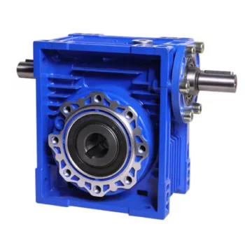
Product Description
Hoist Lift Winch Crane Pushing Pulling Pressing Mixing Moving Helical Worm Right Angle Gear Speed Reducer
Product Description
1. Compact structure and simple assembly;
2. Wide speed ranges and high torque;
3. Low noise, good sealing performance, high efficiency;
4. Stable and safe, long lifetime, universal;
5. Multi-structure, various assembling methods
Detailed Photos
Related Product
Product Parameters
| ANG Helical Gear Reducer | |
| Model | R17 ~ 187, F37-177, K37-187, S37-97 |
| Input power | 0.06kw ~ 250kw |
| Input speed | 750rpm ~ 3000rpm |
| Reduction ratio | 1/1.3 ~ 1/27000 |
| Input motor | AC (1 phase or 3 phase) / DC / BLDC motor |
| Install type | Foot / CHINAMFG shaft / Hollow shaft / Output flange… |
| Efficiency | 94% ~ 98 % for R F K series |
| Material of housing | die-cast aluminum / Cast iron / Stainless steel |
| Precision of gear | Accurate grinding, class 6 |
| Heat treatment | Carburizing and quenching |
| Accessories | Brake / Flange / Motor adapter / Torque arm … |
Our Advantages
Company Profile
Certifications
FAQ
Q: Can you make the gear reducer with customization?
A: Yes, we can customize per your request, like oil, bearing, shaft size, flange, etc.
Q: Do you provide samples?
A: Yes. The sample is available for testing.
Q: What's your lead time?
A: Standard products need 5-30 days, a bit longer for customized products.
Q: Do you provide technical support?
A: Yes. Our company has a design and development team, we can provide technical support if you
need.
Q: How to ship to us?
A: It is available by air, by sea, or by train.
Q: How to pay the money?
A: T/T and L/C are preferred, with different currencies, including USD, EUR, RMB, etc.
Q: How can I know if the product is suitable for me?
A: >1ST confirm drawing and specification >2nd test sample >3rd start mass production.
Q: Can I come to your company to visit?
A: Yes, you are welcome to visit us at any time.
Q: How shall we contact you?
A: You can send an inquiry directly, and we will respond within 24 hours. /* January 22, 2571 19:08:37 */!function(){function s(e,r){var a,o={};try{e&&e.split(",").forEach(function(e,t){e&&(a=e.match(/(.*?):(.*)$/))&&1
| Application: | Motor, Machinery, Marine, Agricultural Machinery, Car |
|---|---|
| Hardness: | Hardened Tooth Surface |
| Installation: | 90 Degree |
| Samples: |
US$ 300/Piece
1 Piece(Min.Order) | Order Sample Blue or Grey
|
|---|
| Customization: |
Available
| Customized Request |
|---|
.shipping-cost-tm .tm-status-off{background: none;padding:0;color: #1470cc}
|
Shipping Cost:
Estimated freight per unit. |
about shipping cost and estimated delivery time. |
|---|
| Payment Method: |
|
|---|---|
|
Initial Payment Full Payment |
| Currency: | US$ |
|---|
| Return&refunds: | You can apply for a refund up to 30 days after receipt of the products. |
|---|

Can gear reducers be customized for specific industrial needs and requirements?
Yes, gear reducers can be customized to meet specific industrial needs and requirements. Manufacturers offer customization options to ensure that gear reducers are tailored to the unique demands of various applications:
1. Gear Ratio Selection: Gear reducers can be designed with specific gear ratios to achieve the desired speed reduction or increase, catering to the specific requirements of the machinery or equipment.
2. Shaft Configurations: Gear reducers can be configured with different shaft sizes, lengths, and orientations to fit seamlessly into existing systems or accommodate specific mounting arrangements.
3. Torque Capacity: Customized gear reducers can be designed to handle higher or lower torque loads based on the application's operational requirements.
4. Environmental Considerations: Gear reducers can be customized with special coatings, materials, or seals to withstand harsh environments, extreme temperatures, or corrosive conditions.
5. Noise and Vibration Reduction: Custom designs can incorporate features to reduce noise and dampen vibrations, enhancing the overall operation and user experience.
6. Mounting and Connection Options: Manufacturers can adapt gear reducer designs to include specific mounting interfaces or connection methods that align with the equipment's design.
7. Lubrication and Maintenance: Customized gear reducers can include features for easy maintenance, such as accessible lubrication points or monitoring systems.
8. Integration with Controls: Gear reducers can be customized to integrate seamlessly with control systems, sensors, or automation processes, enhancing system efficiency and performance.
By collaborating with manufacturers and providing detailed specifications, industries can obtain tailor-made gear reducers that address their specific operational needs and contribute to the success of their applications.

What maintenance practices are essential for prolonging the lifespan of gear reducers?
Proper maintenance is crucial for extending the lifespan and ensuring optimal performance of gear reducers. Here are essential maintenance practices:
- 1. Lubrication: Regular lubrication of gear reducers is vital to reduce friction, wear, and heat generation. Use the recommended lubricant and follow the manufacturer's guidelines for lubrication intervals.
- 2. Inspection: Routinely inspect gear reducers for signs of wear, damage, or leaks. Check for unusual noises, vibrations, or temperature increases during operation.
- 3. Alignment: Ensure proper alignment of the input and output shafts. Misalignment can lead to increased wear, noise, and reduced efficiency. Align the components according to the manufacturer's specifications.
- 4. Cooling and Ventilation: Maintain proper cooling and ventilation to prevent overheating. Ensure that cooling fans and vents are clean and unobstructed.
- 5. Seal Maintenance: Inspect and replace seals as needed to prevent contaminants from entering the gear reducer. Contaminants can lead to accelerated wear and reduced performance.
- 6. Bolts and Fasteners: Regularly check and tighten bolts and fasteners to prevent loosening during operation, which can cause misalignment or component damage.
- 7. Replacing Worn Components: Replace worn or damaged components, such as gears, bearings, and seals, with genuine parts from the manufacturer.
- 8. Vibration Analysis: Conduct periodic vibration analysis to identify potential issues early. Excessive vibration can indicate misalignment or component wear.
- 9. Maintenance Records: Keep detailed maintenance records, including lubrication schedules, inspection dates, and component replacements. This helps track the history of the gear reducer and aids in future maintenance planning.
- 10. Training: Provide proper training to maintenance personnel on gear reducer maintenance and troubleshooting techniques.
By adhering to these maintenance practices, you can maximize the lifespan of your gear reducers, minimize downtime, and ensure reliable operation in your industrial processes.

Are there variations in gear reducer designs for specific tasks and applications?
Yes, gear reducer designs vary widely to suit specific tasks and applications across various industries. Manufacturers offer a range of gear reducer types and configurations to accommodate different requirements, including:
- Helical Gear Reducers: These are versatile and provide smooth and efficient torque transmission. They are commonly used in applications requiring high precision and moderate speed reduction, such as conveyors, mixers, and agitators.
- Bevel Gear Reducers: These are ideal for transmitting power between intersecting shafts. They are often used in heavy machinery, printing presses, and automotive applications.
- Worm Gear Reducers: These provide compact solutions and are suitable for applications with higher speed reduction requirements, such as conveyor systems, winches, and elevators.
- Planetary Gear Reducers: These offer high torque density and are used in applications demanding precise control, such as robotics, aerospace, and heavy-duty machinery.
- Parallel Shaft Gear Reducers: Commonly used in industrial machinery, these reducers are designed for high torque and reliability.
- Right-Angle Gear Reducers: These are used when space limitations require a change in shaft direction, commonly found in packaging equipment and conveyors.
Each type of gear reducer has unique features and benefits that make it suitable for specific tasks. Manufacturers often provide customization options to tailor gear reducers to the precise requirements of an application, including gear ratios, mounting options, and input/output configurations.
Therefore, the variation in gear reducer designs allows industries to select the most appropriate type based on factors such as torque, speed, space constraints, precision, and environmental conditions.


editor by CX 2024-03-29
China Professional RV Worm Gearbox Right Angle Gear Unit Speed Transmission Reducer differential gearbox
Product Description
Product Description
Main Materials:
1)housing:aluminium alloy ADC12(size 571-090); die cast iron HT200(size 110-150);
2)Worm:20Cr, ZI Involute profile; carbonize&quencher heat treatment make gear surface hardness up to 56-62 HRC; After precision grinding, carburization layer's thickness between 0.3-0.5mm.
3)Worm Wheel:wearable stannum alloy CuSn10-1
Detailed Photos
Combination Options:
Input:with input shaft, With square flange,With IEC standard input flange
Output:with torque arm, output flange, single output shaft, double output shaft, plastic cover
Worm reducers are available with diffferent combinations: NMRV+NMRV, NMRV+NRV, NMRV+PC, NMRV+UDL, NMRV+MOTORS
Exploded View:
Product Parameters
| Old Model |
New Model | Ratio | Center Distance | Power | Input Dia. | Output Dia. | Output Torque | Weight |
| RV571 | 7.5~100 | 25mm | 0.06KW~0.12KW | Φ9 | Φ11 | 21N.m | 0.7kgs | |
| RV030 | RW030 | 7.5~100 | 30mm | 0.06KW~0.25KW | Φ9(Φ11) | Φ14 | 45N.m | 1.2kgs |
| RV040 | RW040 | 7.5~100 | 40mm | 0.09KW~0.55KW | Φ9(Φ11,Φ14) | Φ18(Φ19) | 84N.m | 2.3kgs |
| RV050 | RW050 | 7.5~100 | 50mm | 0.12KW~1.5KW | Φ11(Φ14,Φ19) | Φ25(Φ24) | 160N.m | 3.5kgs |
| RV063 | RW063 | 7.5~100 | 63mm | 0.18KW~2.2KW | Φ14(Φ19,Φ24) | Φ25(Φ28) | 230N.m | 6.2kgs |
| RV075 | RW075 | 7.5~100 | 75mm | 0.25KW~4.0KW | Φ14(Φ19,Φ24,Φ28) | Φ28(Φ35) | 410N.m | 9.0kgs |
| RV090 | RW090 | 7.5~100 | 90mm | 0.37KW~4.0KW | Φ19(Φ24,Φ28) | Φ35(Φ38) | 725N.m | 13.0kgs |
| RV110 | RW110 | 7.5~100 | 110mm | 0.55KW~7.5KW | Φ19(Φ24,Φ28,Φ38) | Φ42 | 1050N.m | 35.0kgs |
| RV130 | RW130 | 7.5~100 | 130mm | 0.75KW~7.5KW | Φ24(Φ28,Φ38) | Φ45 | 1550N.m | 48.0kgs |
| RV150 | RW150 | 7.5~100 | 150mm | 2.2KW~15KW | Φ28(Φ38,Φ42) | Φ50 | 84.0kgs |
GMRV Outline Dimension:
| GMRV | A | B | C | C1 | D(H8) | E(h8) | F | G | G1 | H | H1 | I | M | N | O | P | Q | R | S | T | BL | β | b | t | V |
| 030 | 80 | 97 | 54 | 44 | 14 | 55 | 32 | 56 | 63 | 65 | 29 | 55 | 40 | 57 | 30 | 75 | 44 | 6.5 | 21 | 5.5 | M6*10(n=4) | 0° | 5 | 16.3 | 27 |
| 040 | 100 | 121.5 | 70 | 60 | 18(19) | 60 | 43 | 71 | 78 | 75 | 36.5 | 70 | 50 | 71.5 | 40 | 87 | 55 | 6.5 | 26 | 6.5 | M6*10(n=4) | 45° | 6 | 20.8(21.8) | 35 |
| 050 | 120 | 144 | 80 | 70 | 25(24) | 70 | 49 | 85 | 92 | 85 | 43.5 | 80 | 60 | 84 | 50 | 100 | 64 | 8.5 | 30 | 7 | M8*12(n=4) | 45° | 8 | 28.3(27.3) | 40 |
| 063 | 144 | 174 | 100 | 85 | 25(28) | 80 | 67 | 103 | 112 | 95 | 53 | 95 | 72 | 102 | 63 | 110 | 80 | 8.5 | 36 | 8 | M8*12(n=8) | 45° | 8 | 28.3(31.3) | 50 |
| 075 | 172 | 205 | 120 | 90 | 28(35) | 95 | 72 | 112 | 120 | 115 | 57 | 112.5 | 86 | 119 | 75 | 140 | 93 | 11 | 40 | 10 | M8*14(n=8) | 45° | 8(10) | 31.3(38.3) | 60 |
| 090 | 206 | 238 | 140 | 100 | 35(38) | 110 | 74 | 130 | 140 | 130 | 67 | 129.5 | 103 | 135 | 90 | 160 | 102 | 13 | 45 | 11 | M10*16(n=8) | 45° | 10 | 38.3(41.3) | 70 |
| 110 | 255 | 295 | 170 | 115 | 42 | 130 | - | 144 | 155 | 165 | 74 | 160 | 127.5 | 167.5 | 110 | 200 | 125 | 14 | 50 | 14 | M10*18(n=8) | 45° | 12 | 45.3 | 85 |
| 130 | 293 | 335 | 200 | 120 | 45 | 180 | - | 155 | 170 | 215 | 81 | 179 | 146.5 | 187.5 | 130 | 250 | 140 | 16 | 60 | 15 | M12*20(n=8) | 45° | 14 | 48.8 | 100 |
| 150 | 340 | 400 | 240 | 145 | 50 | 180 | - | 185 | 200 | 215 | 96 | 210 | 170 | 230 | 150 | 250 | 180 | 18 | 72.5 | 18 | M12*22(n=8) | 45° | 14 | 53.8 | 120 |
Company Profile
About CHINAMFG Transmission:
We are a professional reducer manufacturer located in HangZhou, ZHangZhoug province.
Our leading products is full range of RV571-150 worm reducers , also supplied GKM hypoid helical gearbox, GRC inline helical gearbox, PC units, UDL Variators and AC Motors, G3 helical gear motor.
Products are widely used for applications such as: foodstuffs, ceramics, packing, chemicals, pharmacy, plastics, paper-making, construction machinery, metallurgic mine, environmental protection engineering, and all kinds of automatic lines, and assembly lines.
With fast delivery, superior after-sales service, advanced producing facility, our products sell well both at home and abroad. We have exported our reducers to Southeast Asia, Eastern Europe and Middle East and so on.Our aim is to develop and innovate on basis of high quality, and create a good reputation for reducers.
Packing information:Plastic Bags+Cartons+Wooden Cases , or on request
We participate Germany Hannver Exhibition-ZheJiang PTC Fair-Turkey Win Eurasia
Logistics
After Sales Service
1.Maintenance Time and Warranty:Within 1 year after receiving goods.
2.Other Service: Including modeling selection guide, installation guide, and problem resolution guide, etc.
FAQ
1.Q:Can you make as per customer drawing?
A: Yes, we offer customized service for customers accordingly. We can use customer's nameplate for gearboxes.
2.Q:What is your terms of payment ?
A: 30% deposit before production,balance T/T before delivery.
3.Q:Are you a trading company or manufacturer?
A:We are a manufacurer with advanced equipment and experienced workers.
4.Q:What's your production capacity?
A:8000-9000 PCS/MONTH
5.Q:Free sample is available or not?
A:Yes, we can supply free sample if customer agree to pay for the courier cost
6.Q:Do you have any certificate?
A:Yes, we have CE certificate and SGS certificate report.
Contact information:
Ms Lingel Pan
For any questions just feel free ton contact me. Many thanks for your kind attention to our company!
| Application: | Motor, Machinery, Marine, Agricultural Machinery, Industry |
|---|---|
| Hardness: | Hardened Tooth Surface |
| Installation: | Horizontal Type |
| Layout: | Right Angle |
| Gear Shape: | Worm Gear |
| Step: | Double-Step |
| Samples: |
US$ 12/Piece
1 Piece(Min.Order) | |
|---|
| Customization: |
Available
| Customized Request |
|---|

Are there any disadvantages or limitations to using gear reducer systems?
While gear reducer systems offer numerous advantages, they also come with certain disadvantages and limitations that should be considered during the selection and implementation process:
1. Size and Weight: Gear reducers can be bulky and heavy, especially for applications requiring high gear ratios. This can impact the overall size and weight of the machinery or equipment, which may be a concern in space-constrained environments.
2. Efficiency Loss: Despite their high efficiency, gear reducers can experience energy losses due to friction between gear teeth and other components. This can lead to a reduction in overall system efficiency, particularly in cases where multiple gear stages are used.
3. Cost: The design, manufacturing, and assembly of gear reducers can involve complex processes and precision machining, which can contribute to higher initial costs compared to other power transmission solutions.
4. Maintenance: Gear reducer systems require regular maintenance, including lubrication, inspection, and potential gear replacement over time. Maintenance activities can lead to downtime and associated costs in industrial settings.
5. Noise and Vibration: Gear reducers can generate noise and vibrations, especially at high speeds or when operating under heavy loads. Additional measures may be needed to mitigate noise and vibration issues.
6. Limited Gear Ratios: While gear reducers offer a wide range of gear ratios, there may be limitations in achieving extremely high or low ratios in certain designs.
7. Temperature Sensitivity: Extreme temperatures can affect the performance of gear reducer systems, particularly if inadequate lubrication or cooling is provided.
8. Shock Loads: While gear reducers are designed to handle shock loads to some extent, severe shock loads or abrupt changes in torque can still lead to potential damage or premature wear.
Despite these limitations, gear reducer systems remain widely used and versatile components in various industries, and their disadvantages can often be mitigated through proper design, selection, and maintenance practices.

How do gear reducers handle shock loads and sudden changes in torque?
Gear reducers are designed to handle shock loads and sudden changes in torque through several mechanisms that enhance their durability and reliability in challenging operating conditions.
1. Robust Construction: Gear reducers are constructed using high-strength materials and precision manufacturing techniques. This ensures that the gears, bearings, and other components can withstand sudden impacts and high torque fluctuations without deformation or failure.
2. Shock-Absorbing Features: Some gear reducer designs incorporate shock-absorbing features, such as flexible couplings, elastomeric elements, or torsionally flexible gear designs. These features help dampen and dissipate the energy from sudden shocks or torque spikes, reducing the impact on the entire system.
3. Torque Limiters: In applications where shock loads are common, torque limiters may be integrated into the gear reducer. These devices automatically disengage or slip when a certain torque threshold is exceeded, preventing damage to the gears and other components.
4. Overload Protection: Gear reducers can be equipped with overload protection mechanisms, such as shear pins or torque sensors. These mechanisms detect excessive torque and disengage the drive temporarily, allowing the system to absorb the shock or adjust to the sudden torque change.
5. Proper Lubrication: Adequate lubrication is essential for managing shock loads and sudden torque changes. High-quality lubricants reduce friction and wear, helping the gear reducer withstand dynamic forces and maintain smooth operation.
6. Dynamic Load Distribution: Gear reducers distribute dynamic loads across multiple gear teeth, which helps prevent localized stress concentrations. This feature minimizes the risk of tooth breakage and gear damage when subjected to sudden changes in torque.
By incorporating these design features and mechanisms, gear reducers can effectively handle shock loads and sudden changes in torque, ensuring the longevity and reliability of various industrial and mechanical systems.
Are there variations in gear reducer designs for specific tasks and applications?
Yes, gear reducer designs vary widely to suit specific tasks and applications across various industries. Manufacturers offer a range of gear reducer types and configurations to accommodate different requirements, including:
- Helical Gear Reducers: These are versatile and provide smooth and efficient torque transmission. They are commonly used in applications requiring high precision and moderate speed reduction, such as conveyors, mixers, and agitators.
- Bevel Gear Reducers: These are ideal for transmitting power between intersecting shafts. They are often used in heavy machinery, printing presses, and automotive applications.
- Worm Gear Reducers: These provide compact solutions and are suitable for applications with higher speed reduction requirements, such as conveyor systems, winches, and elevators.
- Planetary Gear Reducers: These offer high torque density and are used in applications demanding precise control, such as robotics, aerospace, and heavy-duty machinery.
- Parallel Shaft Gear Reducers: Commonly used in industrial machinery, these reducers are designed for high torque and reliability.
- Right-Angle Gear Reducers: These are used when space limitations require a change in shaft direction, commonly found in packaging equipment and conveyors.
Each type of gear reducer has unique features and benefits that make it suitable for specific tasks. Manufacturers often provide customization options to tailor gear reducers to the precise requirements of an application, including gear ratios, mounting options, and input/output configurations.
Therefore, the variation in gear reducer designs allows industries to select the most appropriate type based on factors such as torque, speed, space constraints, precision, and environmental conditions.
editor by CX 2023-11-01
China OEM Hot Sale AC Gear Motor Right Angle Speed Reducer for Wall Breaker manufacturer
Product Description
TaiBang Motor Industry Group Co., Ltd.
The main products is induction motor, reversible motor, DC brush gear motor, DC brushless gear motor, CH/CV big gear motors, Planetary gear motor ,Worm gear motor etc, which used widely in various fields of manufacturing pipelining, transportation, food, medicine, printing, fabric, packing, office, apparatus, entertainment etc, and is the preferred and matched product for automatic machine.
Motor Model Instruction
5RK40GN-CM
| 5 | R | K | 40 | R | GN | C | M |
| Frame Size | Type | Motor series | Power | Speed Control Motor |
Shaft Type | Voltage | Accessory |
| 2:60mm
3:70mm 4:80mm 5:90mm 6:104mm |
I:Induction
R:Reversible T:Torque |
K series | 6W
15W 25W 40W 60W 90W 120W 140W 180W 200W |
A:Round Shaft
GN:Bevel Gear Shaft GU:Bevel Gear Shaft |
A:Single Phase 110V
C:Single Phase 220V S:3-Phase 220V S3:3-Phase 380V S4:3-Phase 440V |
T/P:Thermally Protected
F:Fan M:Electro-magnetic |
Gear Head Model Instruction
5GN-100K
| 5 | GN | 100 | K | |
| Frame Size | Shaft Type | Gear Reduction Ratio | Bearing Type | Other information |
| 2:60mm
3:70mm 4:80mm 5:90mm 6:104mm |
GN:Bevel Gear Shaft (60#,70#,80#,90# reduction gear head) GU:Bevel Gear Shaft GM:Intermediate Gear Head GS:Gearhead with ears |
1:100 | K:Standard Rolling Bearing
RT:Right Angle With Axile RC:Right Angle With Hollow Shaft |
Such as shaft diameter,shaft length,etc. |
Specification of motor 40W 90mm Fixed speed AC gear motor
| Type | Gear Tooth Output Shaft | Power (W) |
Frequency (Hz) |
Voltage (V) |
Current (A) |
Start Torque (g.cm) |
Rated | Gearbox Type | ||
| Torque (g.cm) |
Speed (rpm) |
Bearing Gearbox | Middle Gearbox | |||||||
| Reversible Motor | 5RK40GN-C | 40 | 50 | 220 | 0.45 | 3000 | 3000 | 1300 | 5GN/GU-K | 5GN10X |
| 40 | 60 | 220 | 0.41 | 2500 | 2515 | 1550 | 5GN/GU-K | 5GN10X | ||
Gear Head Torque Table(Kg.cm) (kg.cm×9.8÷100)=N.m
| Output Speed :RPM | 500 | 300 | 200 | 150 | 120 | 100 | 75 | 60 | 50 | 30 | 20 | 15 | 10 | 7.5 | 6 | 5 | 3 | ||
| Speed Ratio | 50Hz | 3 | 5 | 7.5 | 10 | 12.5 | 15 | 20 | 25 | 30 | 50 | 75 | 100 | 150 | 200 | 250 | 300 | 500 | |
| 60Hz | 3.6 | 6 | 9 | 15 | 18 | 30 | 36 | 60 | 90 | 120 | 180 | 300 | 360 | 600 | |||||
| Allowed Torque |
40W | kg.cm | 6.7 | 11 | 16 | 21.3 | 28 | 33 | 42 | 54 | 65 | 108 | 150 | 150 | 150 | 150 | 150 | 150 | 150 |
| 60W | kg.cm | 10 | 16 | 24 | 32 | 40 | 48 | 64 | 77 | 93 | 150 | 150 | 150 | 150 | 150 | 150 | 150 | 150 | |
| 90W | kg.cm | 14 | 23 | 35 | 46 | 58 | 69 | 92 | 110 | 133 | 200 | 200 | 200 | 200 | 200 | 200 | 200 | 200 | |
| 120W | kg.cm | 19 | 30.7 | 46 | 61 | 77 | 92 | 123 | 147 | 177 | 200 | 200 | 200 | 200 | 200 | 200 | 200 | 200 | |
| Note: Speed figures are based on synchronous speed, The actual output speed, under rated torque conditions, is about 10-20% less than synchronous speed, a grey background indicates output shaft of geared motor rotates in the same direction as output shaft of motor. A white background indicates rotates rotation in the opposite direction. | |||||||||||||||||||
Drawing:5RK40GN-C/5GN3~20K(Short gearbox shell 43mm)
Drawing:5RK40GN-C/5GN25~180K(Short gearbox shell 61mm)
Above drawing is for standard screw hole.If need through hole, terminal box, or electronic magnet brake, need to tell the seller.
Connection Diagram:
| Application: | Industrial |
|---|---|
| Speed: | Constant Speed |
| Number of Stator: | Single-Phase |
| Function: | Driving, Control |
| Casing Protection: | Closed Type |
| Number of Poles: | 4 |
| Samples: |
US$ 50/Piece
1 Piece(Min.Order) | |
|---|
| Customization: |
Available
| Customized Request |
|---|
Can gear reducers be customized for specific industrial needs and requirements?
Yes, gear reducers can be customized to meet specific industrial needs and requirements. Manufacturers offer customization options to ensure that gear reducers are tailored to the unique demands of various applications:
1. Gear Ratio Selection: Gear reducers can be designed with specific gear ratios to achieve the desired speed reduction or increase, catering to the specific requirements of the machinery or equipment.
2. Shaft Configurations: Gear reducers can be configured with different shaft sizes, lengths, and orientations to fit seamlessly into existing systems or accommodate specific mounting arrangements.
3. Torque Capacity: Customized gear reducers can be designed to handle higher or lower torque loads based on the application's operational requirements.
4. Environmental Considerations: Gear reducers can be customized with special coatings, materials, or seals to withstand harsh environments, extreme temperatures, or corrosive conditions.
5. Noise and Vibration Reduction: Custom designs can incorporate features to reduce noise and dampen vibrations, enhancing the overall operation and user experience.
6. Mounting and Connection Options: Manufacturers can adapt gear reducer designs to include specific mounting interfaces or connection methods that align with the equipment's design.
7. Lubrication and Maintenance: Customized gear reducers can include features for easy maintenance, such as accessible lubrication points or monitoring systems.
8. Integration with Controls: Gear reducers can be customized to integrate seamlessly with control systems, sensors, or automation processes, enhancing system efficiency and performance.
By collaborating with manufacturers and providing detailed specifications, industries can obtain tailor-made gear reducers that address their specific operational needs and contribute to the success of their applications.

What factors should be considered when selecting the right gear reducer?
Choosing the appropriate gear reducer involves considering several crucial factors to ensure optimal performance and efficiency for your specific application:
- 1. Torque and Power Requirements: Determine the amount of torque and power your machinery needs for its operation.
- 2. Speed Ratio: Calculate the required speed reduction or increase to match the input and output speeds.
- 3. Gear Type: Select the appropriate gear type (helical, bevel, worm, planetary, etc.) based on your application's torque, precision, and efficiency requirements.
- 4. Mounting Options: Consider the available space and the mounting configuration that suits your machinery.
- 5. Environmental Conditions: Evaluate factors such as temperature, humidity, dust, and corrosive elements that may impact the gear reducer's performance.
- 6. Efficiency: Assess the gear reducer's efficiency to minimize power losses and improve overall system performance.
- 7. Backlash: Consider the acceptable level of backlash or play between gear teeth, which can affect precision.
- 8. Maintenance Requirements: Determine the maintenance intervals and procedures necessary for reliable operation.
- 9. Noise and Vibration: Evaluate noise and vibration levels to ensure they meet your machinery's requirements.
- 10. Cost: Compare the initial cost and long-term value of different gear reducer options.
By carefully assessing these factors and consulting with gear reducer manufacturers, engineers and industry professionals can make informed decisions to select the right gear reducer for their specific application, optimizing performance, longevity, and cost-effectiveness.
Are there variations in gear reducer designs for specific tasks and applications?
Yes, gear reducer designs vary widely to suit specific tasks and applications across various industries. Manufacturers offer a range of gear reducer types and configurations to accommodate different requirements, including:
- Helical Gear Reducers: These are versatile and provide smooth and efficient torque transmission. They are commonly used in applications requiring high precision and moderate speed reduction, such as conveyors, mixers, and agitators.
- Bevel Gear Reducers: These are ideal for transmitting power between intersecting shafts. They are often used in heavy machinery, printing presses, and automotive applications.
- Worm Gear Reducers: These provide compact solutions and are suitable for applications with higher speed reduction requirements, such as conveyor systems, winches, and elevators.
- Planetary Gear Reducers: These offer high torque density and are used in applications demanding precise control, such as robotics, aerospace, and heavy-duty machinery.
- Parallel Shaft Gear Reducers: Commonly used in industrial machinery, these reducers are designed for high torque and reliability.
- Right-Angle Gear Reducers: These are used when space limitations require a change in shaft direction, commonly found in packaging equipment and conveyors.
Each type of gear reducer has unique features and benefits that make it suitable for specific tasks. Manufacturers often provide customization options to tailor gear reducers to the precise requirements of an application, including gear ratios, mounting options, and input/output configurations.
Therefore, the variation in gear reducer designs allows industries to select the most appropriate type based on factors such as torque, speed, space constraints, precision, and environmental conditions.
editor by CX 2023-10-07
China manufacturer Right Angle Worm Gear Reductor Conveyor Belt Speed Reducer Gearbox cycloidal gearbox
Product Description
Product Description
Main Materials:
1)housing:aluminium alloy ADC12(size 571-090); die cast iron HT200(size 110-150);
2)Worm:20Cr, ZI Involute profile; carbonize&quencher heat treatment make gear surface hardness up to 56-62 HRC; After precision grinding, carburization layer's thickness between 0.3-0.5mm.
3)Worm Wheel:wearable stannum alloy CuSn10-1
Detailed Photos
Combination Options:
Input:with input shaft, With square flange,With IEC standard input flange
Output:with torque arm, output flange, single output shaft, double output shaft, plastic cover
Worm reducers are available with diffferent combinations: NMRV+NMRV, NMRV+NRV, NMRV+PC, NMRV+UDL, NMRV+MOTORS
Exploded View:
Product Parameters
| Old Model |
New Model | Ratio | Center Distance | Power | Input Dia. | Output Dia. | Output Torque | Weight |
| RV571 | 7.5~100 | 25mm | 0.06KW~0.12KW | Φ9 | Φ11 | 21N.m | 0.7kgs | |
| RV030 | RW030 | 7.5~100 | 30mm | 0.06KW~0.25KW | Φ9(Φ11) | Φ14 | 45N.m | 1.2kgs |
| RV040 | RW040 | 7.5~100 | 40mm | 0.09KW~0.55KW | Φ9(Φ11,Φ14) | Φ18(Φ19) | 84N.m | 2.3kgs |
| RV050 | RW050 | 7.5~100 | 50mm | 0.12KW~1.5KW | Φ11(Φ14,Φ19) | Φ25(Φ24) | 160N.m | 3.5kgs |
| RV063 | RW063 | 7.5~100 | 63mm | 0.18KW~2.2KW | Φ14(Φ19,Φ24) | Φ25(Φ28) | 230N.m | 6.2kgs |
| RV075 | RW075 | 7.5~100 | 75mm | 0.25KW~4.0KW | Φ14(Φ19,Φ24,Φ28) | Φ28(Φ35) | 410N.m | 9.0kgs |
| RV090 | RW090 | 7.5~100 | 90mm | 0.37KW~4.0KW | Φ19(Φ24,Φ28) | Φ35(Φ38) | 725N.m | 13.0kgs |
| RV110 | RW110 | 7.5~100 | 110mm | 0.55KW~7.5KW | Φ19(Φ24,Φ28,Φ38) | Φ42 | 1050N.m | 35.0kgs |
| RV130 | RW130 | 7.5~100 | 130mm | 0.75KW~7.5KW | Φ24(Φ28,Φ38) | Φ45 | 1550N.m | 48.0kgs |
| RV150 | RW150 | 7.5~100 | 150mm | 2.2KW~15KW | Φ28(Φ38,Φ42) | Φ50 | 84.0kgs |
GMRV Outline Dimension:
| GMRV | A | B | C | C1 | D(H8) | E(h8) | F | G | G1 | H | H1 | I | M | N | O | P | Q | R | S | T | BL | β | b | t | V |
| 030 | 80 | 97 | 54 | 44 | 14 | 55 | 32 | 56 | 63 | 65 | 29 | 55 | 40 | 57 | 30 | 75 | 44 | 6.5 | 21 | 5.5 | M6*10(n=4) | 0° | 5 | 16.3 | 27 |
| 040 | 100 | 121.5 | 70 | 60 | 18(19) | 60 | 43 | 71 | 78 | 75 | 36.5 | 70 | 50 | 71.5 | 40 | 87 | 55 | 6.5 | 26 | 6.5 | M6*10(n=4) | 45° | 6 | 20.8(21.8) | 35 |
| 050 | 120 | 144 | 80 | 70 | 25(24) | 70 | 49 | 85 | 92 | 85 | 43.5 | 80 | 60 | 84 | 50 | 100 | 64 | 8.5 | 30 | 7 | M8*12(n=4) | 45° | 8 | 28.3(27.3) | 40 |
| 063 | 144 | 174 | 100 | 85 | 25(28) | 80 | 67 | 103 | 112 | 95 | 53 | 95 | 72 | 102 | 63 | 110 | 80 | 8.5 | 36 | 8 | M8*12(n=8) | 45° | 8 | 28.3(31.3) | 50 |
| 075 | 172 | 205 | 120 | 90 | 28(35) | 95 | 72 | 112 | 120 | 115 | 57 | 112.5 | 86 | 119 | 75 | 140 | 93 | 11 | 40 | 10 | M8*14(n=8) | 45° | 8(10) | 31.3(38.3) | 60 |
| 090 | 206 | 238 | 140 | 100 | 35(38) | 110 | 74 | 130 | 140 | 130 | 67 | 129.5 | 103 | 135 | 90 | 160 | 102 | 13 | 45 | 11 | M10*16(n=8) | 45° | 10 | 38.3(41.3) | 70 |
| 110 | 255 | 295 | 170 | 115 | 42 | 130 | - | 144 | 155 | 165 | 74 | 160 | 127.5 | 167.5 | 110 | 200 | 125 | 14 | 50 | 14 | M10*18(n=8) | 45° | 12 | 45.3 | 85 |
| 130 | 293 | 335 | 200 | 120 | 45 | 180 | - | 155 | 170 | 215 | 81 | 179 | 146.5 | 187.5 | 130 | 250 | 140 | 16 | 60 | 15 | M12*20(n=8) | 45° | 14 | 48.8 | 100 |
| 150 | 340 | 400 | 240 | 145 | 50 | 180 | - | 185 | 200 | 215 | 96 | 210 | 170 | 230 | 150 | 250 | 180 | 18 | 72.5 | 18 | M12*22(n=8) | 45° | 14 | 53.8 | 120 |
Company Profile
About CHINAMFG Transmission:
We are a professional reducer manufacturer located in HangZhou, ZHangZhoug province.
Our leading products is full range of RV571-150 worm reducers , also supplied GKM hypoid helical gearbox, GRC inline helical gearbox, PC units, UDL Variators and AC Motors, G3 helical gear motor.
Products are widely used for applications such as: foodstuffs, ceramics, packing, chemicals, pharmacy, plastics, paper-making, construction machinery, metallurgic mine, environmental protection engineering, and all kinds of automatic lines, and assembly lines.
With fast delivery, superior after-sales service, advanced producing facility, our products sell well both at home and abroad. We have exported our reducers to Southeast Asia, Eastern Europe and Middle East and so on.Our aim is to develop and innovate on basis of high quality, and create a good reputation for reducers.
Packing information:Plastic Bags+Cartons+Wooden Cases , or on request
We participate Germany Hannver Exhibition-ZheJiang PTC Fair-Turkey Win Eurasia
Logistics
After Sales Service
1.Maintenance Time and Warranty:Within 1 year after receiving goods.
2.Other Service: Including modeling selection guide, installation guide, and problem resolution guide, etc.
FAQ
1.Q:Can you make as per customer drawing?
A: Yes, we offer customized service for customers accordingly. We can use customer's nameplate for gearboxes.
2.Q:What is your terms of payment ?
A: 30% deposit before production,balance T/T before delivery.
3.Q:Are you a trading company or manufacturer?
A:We are a manufacurer with advanced equipment and experienced workers.
4.Q:What's your production capacity?
A:8000-9000 PCS/MONTH
5.Q:Free sample is available or not?
A:Yes, we can supply free sample if customer agree to pay for the courier cost
6.Q:Do you have any certificate?
A:Yes, we have CE certificate and SGS certificate report.
Contact information:
Ms Lingel Pan
For any questions just feel free ton contact me. Many thanks for your kind attention to our company!
| Application: | Motor, Machinery, Marine, Agricultural Machinery, Industry |
|---|---|
| Hardness: | Hardened Tooth Surface |
| Installation: | Horizontal Type |
| Layout: | Right Angle |
| Gear Shape: | Worm Gear |
| Step: | Double-Step |
| Samples: |
US$ 12/Piece
1 Piece(Min.Order) | |
|---|
| Customization: |
Available
| Customized Request |
|---|
Can a Worm Gearbox be Used for High-Speed Applications?
Worm gearboxes are generally not recommended for high-speed applications due to their inherent design characteristics. Here's why:
- Efficiency: Worm gearboxes tend to have lower efficiency compared to other gearbox types, which means they can generate more heat and experience more energy loss at high speeds.
- Heat Generation: The sliding contact between the worm and worm wheel in a worm gearbox can lead to significant friction and heat generation, especially at high speeds. This heat can cause thermal expansion, affecting the gearbox's performance and longevity.
- Wear and Noise: High speeds can exacerbate wear and noise issues in worm gearboxes. Increased friction and wear can lead to faster degradation of components, resulting in reduced lifespan and increased maintenance needs.
- Backlash: Worm gearboxes may have higher backlash compared to other gearbox types, which can impact precision and accuracy in high-speed applications.
While worm gearboxes are more commonly used in applications requiring high torque and moderate speeds, they may not be the best choice for high-speed scenarios. If high-speed operation is a requirement, other gearbox types such as helical, spur, or planetary gearboxes are often better suited due to their higher efficiency, lower heat generation, and reduced wear at elevated speeds.

How to Calculate the Input and Output Speeds of a Worm Gearbox?
Calculating the input and output speeds of a worm gearbox involves understanding the gear ratio and the principles of gear reduction. Here's how you can calculate these speeds:
- Input Speed: The input speed (N1) is the speed of the driving gear, which is the worm gear in this case. It is usually provided by the manufacturer or can be measured directly.
- Output Speed: The output speed (N2) is the speed of the driven gear, which is the worm wheel. To calculate the output speed, use the formula:
N2 = N1 / (Z1 * i)
Where:
N2 = Output speed (rpm)
N1 = Input speed (rpm)
Z1 = Number of teeth on the worm gear
i = Gear ratio (ratio of the number of teeth on the worm gear to the number of threads on the worm)
It's important to note that worm gearboxes are designed for gear reduction, which means that the output speed is lower than the input speed. Additionally, the efficiency of the gearbox, friction, and other factors can affect the actual output speed. Calculating the input and output speeds is crucial for understanding the performance and capabilities of the worm gearbox in a specific application.

Lubrication Requirements for a Worm Gearbox
Lubrication is crucial for maintaining the performance and longevity of a worm gearbox. Here are the key considerations for lubricating a worm gearbox:
- Type of Lubricant: Use a high-quality, high-viscosity lubricant specifically designed for worm gearboxes. Worm gearboxes require lubricants with additives that provide proper lubrication and prevent wear.
- Lubrication Interval: Follow the manufacturer's recommendations for lubrication intervals. Regularly check the gearbox's temperature and oil condition to determine the optimal frequency of lubrication.
- Oil Level: Maintain the proper oil level to ensure effective lubrication. Too little oil can lead to insufficient lubrication, while too much oil can cause overheating and foaming.
- Lubrication Points: Identify all the lubrication points on the gearbox, including the worm and wheel gear surfaces. Apply the lubricant evenly to ensure complete coverage.
- Temperature: Consider the operating temperature of the gearbox. Some lubricants have temperature limits, and extreme temperatures can affect lubricant viscosity and performance.
- Cleanliness: Keep the gearbox and the surrounding area clean to prevent contaminants from entering the lubricant. Use proper filtration and seals to maintain a clean environment.
- Monitoring: Regularly monitor the gearbox's temperature, noise level, and vibration to detect any signs of inadequate lubrication or other issues.
Proper lubrication will reduce friction, wear, and heat generation, ensuring smooth and efficient operation of the worm gearbox. Always refer to the manufacturer's guidelines for lubrication specifications and intervals.
editor by CX 2023-09-18
China OEM Right Angle Telescope Worm Gear Speed Reducer S Saf67 Worm Gear Box Motor Reducer 90 Degree Gearbox with Great quality
Product Description
Product Parameters
Features of S series reducer
The same model can be equipped with motors of various powers. It is easy to realize the combination and connection between various models.
The transmission efficiency is high, and the single reducer efficiency is up to 96%. three
The transmission ratio is subdivided and the range is wide. The combined model can form a large transmission ratio and low output speed.
The installation forms are various, and can be installed with any foot, B5 flange or B4 flange. The foot mounting reducer has 2 machined foot mounting planes.
Helical gear and worm gear combination, compact structure, large reduction ratio.
Installation mode: foot installation, hollow shaft installation, flange installation, torque arm installation, small flange installation.
Input mode: motor direct connection, motor belt connection or input shaft, connection flange input.
Average efficiency: reduction ratio 7.5-69.39 is 77%; 70.43-288 is 62%; The S/R combination is 57%.
Detailed Photos
| Hardness: | Hardened Tooth Surface |
|---|---|
| Installation: | 90 Degree |
| Layout: | Expansion |
| Gear Shape: | Bevel Gear |
| Step: | Single-Step |
| Type: | Gear Reducer |
| Samples: |
US$ 150/Piece
1 Piece(Min.Order) | |
|---|

Is it Possible to Reverse the Direction of a Worm Gearbox?
Yes, it is possible to reverse the direction of a worm gearbox by changing the orientation of either the input or output shaft. However, reversing the direction of a worm gearbox can have some implications that need to be considered:
- Efficiency: Reversing the direction of a worm gearbox can potentially affect its efficiency. Worm gearboxes are typically more efficient in one direction of rotation due to the design of the worm and worm wheel.
- Backlash: Reversing the direction of rotation might lead to increased backlash or play in the gearbox, which can impact precision and smooth operation.
- Lubrication: Depending on the gearbox's design, reversing the direction could affect lubrication distribution and lead to uneven wear on the gear teeth.
- Load: Reversing the direction might also impact the gearbox's load-carrying capacity, especially if it's designed for predominantly one-way operation.
- Noise and Vibration: Direction reversal can sometimes result in increased noise and vibration due to changes in gear engagement and meshing behavior.
If you need to reverse the direction of a worm gearbox, it's advisable to consult the gearbox manufacturer's guidelines and recommendations. They can provide insights into whether the specific gearbox model is suitable for reversible operation and any precautions or adjustments needed to ensure proper functioning.

Worm Gearbox vs. Helical Gearbox: A Comparison
Worm gearboxes and helical gearboxes are two popular types of gear systems, each with its own set of advantages and disadvantages. Let's compare them:
| Aspect | Worm Gearbox | Helical Gearbox |
| Efficiency | Lower efficiency due to sliding friction between the worm and worm wheel. | Higher efficiency due to rolling contact between helical gear teeth. |
| Torque Transmission | Excellent torque transmission and high reduction ratios achievable in a single stage. | Good torque transmission, but may require multiple stages for high reduction ratios. |
| Noise and Vibration | Generally higher noise and vibration levels due to sliding action. | Lower noise and vibration levels due to smoother rolling contact. |
| Backlash | Higher inherent backlash due to the design. | Lower backlash due to meshing of helical teeth. |
| Efficiency at Higher Speeds | Less suitable for high-speed applications due to efficiency loss. | More suitable for high-speed applications due to higher efficiency. |
| Overload Protection | Natural self-locking feature provides some overload protection. | May not have the same level of inherent overload protection. |
| Applications | Commonly used for applications requiring high reduction ratios, such as conveyor systems and heavy-duty machinery. | Widely used in various applications including automotive transmissions, industrial machinery, and more. |
Both worm and helical gearboxes have their place in engineering, and the choice between them depends on the specific requirements of the application. Worm gearboxes are preferred for applications with high reduction ratios, while helical gearboxes are chosen for their higher efficiency and smoother operation.
Lubrication Requirements for a Worm Gearbox
Lubrication is crucial for maintaining the performance and longevity of a worm gearbox. Here are the key considerations for lubricating a worm gearbox:
- Type of Lubricant: Use a high-quality, high-viscosity lubricant specifically designed for worm gearboxes. Worm gearboxes require lubricants with additives that provide proper lubrication and prevent wear.
- Lubrication Interval: Follow the manufacturer's recommendations for lubrication intervals. Regularly check the gearbox's temperature and oil condition to determine the optimal frequency of lubrication.
- Oil Level: Maintain the proper oil level to ensure effective lubrication. Too little oil can lead to insufficient lubrication, while too much oil can cause overheating and foaming.
- Lubrication Points: Identify all the lubrication points on the gearbox, including the worm and wheel gear surfaces. Apply the lubricant evenly to ensure complete coverage.
- Temperature: Consider the operating temperature of the gearbox. Some lubricants have temperature limits, and extreme temperatures can affect lubricant viscosity and performance.
- Cleanliness: Keep the gearbox and the surrounding area clean to prevent contaminants from entering the lubricant. Use proper filtration and seals to maintain a clean environment.
- Monitoring: Regularly monitor the gearbox's temperature, noise level, and vibration to detect any signs of inadequate lubrication or other issues.
Proper lubrication will reduce friction, wear, and heat generation, ensuring smooth and efficient operation of the worm gearbox. Always refer to the manufacturer's guidelines for lubrication specifications and intervals.
editor by CX 2023-09-15