Product Description
Product Description
The Off supply high precision flange output gearmotor, gear reductor is a new micro precision cycloid and circular gear reducer developed and manufactured by WEITENSTAN together with German and ZheJiang technicians for many years.
High precision miniature cycloidal reducer has the characteristics of smaller, ultra-thin, lightweight and high rigidity, anti-overload and high torque. With good deceleration performance, smooth operation and accurate positioning can be achieved. Integrated design, can be directly connected with the motor, to achieve high precision, high rigidity, high durability and other advantages. It is designed for high speed ratio, high geometric accuracy, low motion loss, large torque capacity and high stiffness applications. The compact design (minimum OD ≈40mm, currently the world's smallest precision cycloidal pin-wheel reducer) allows it to be installed in limited Spaces.
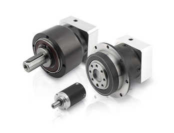
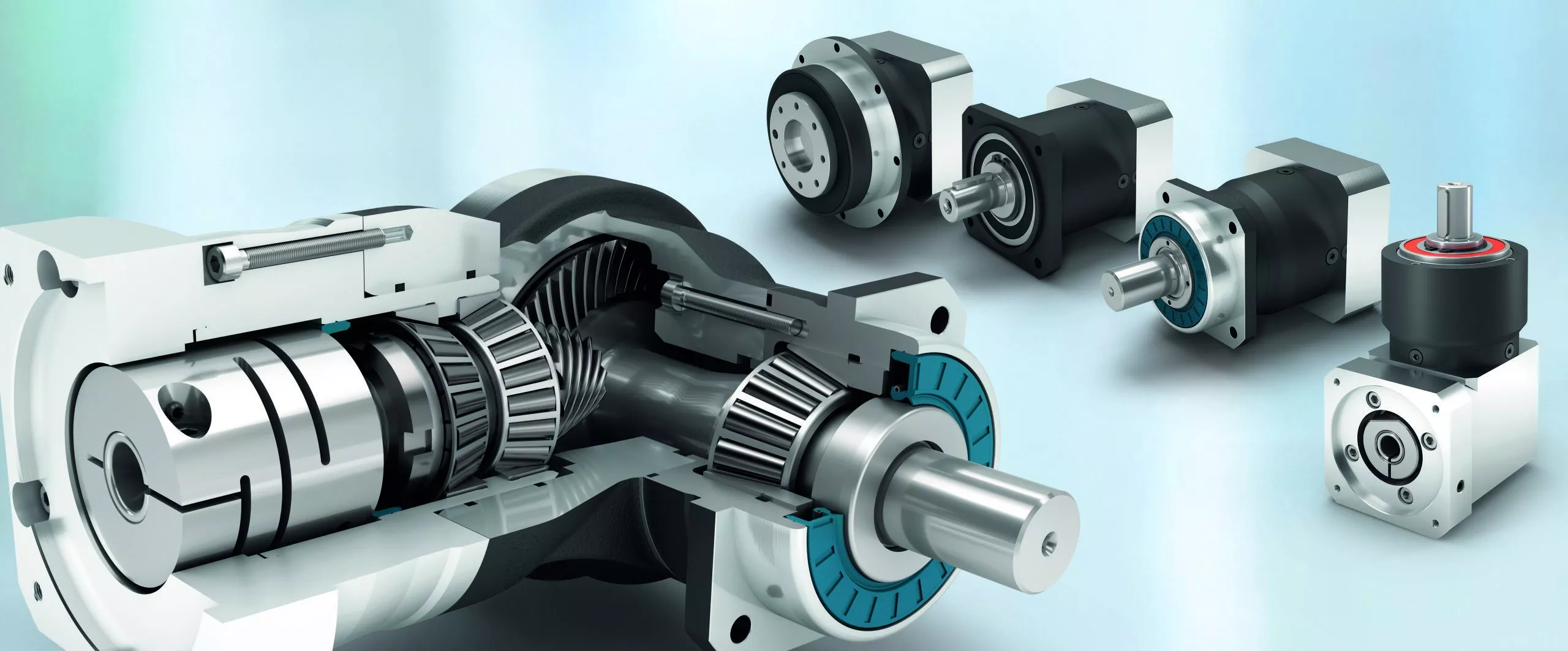
Detailed Photos
Product Advantage
Off supply high precision flange output gearmotor, gear reductor advantages:
1, fine precision cycloidal structure
Ultra flat shape is achieved through differential reduction mechanism and thin cross roller bearing, contributing to the compact size of the equipment. The combination of small size and unmatched superior parameters achieves the best combination of performance, price and size (high cost performance).
2. Excellent accuracy (transmission loss ≤1 arcmin)
Through the complex meshing of precision cycloid gear and high precision roller pin, higher transmission accuracy is achieved while maintaining small size and high speed ratio.
3, high rigidity
Increase the mesh rate to disperse the load, so the rigidity is high.
4. High overload capacity
It maintains trouble-free operation under abnormally low noise and vibration conditions while ensuring excellent overturning and torsional stiffness parameters. Integrated axial radial cross roller bearings, high load capacity and overload capacity of the reducer, can ensure users to provide a variety of temperature range of applications.
5, the motor installation is simple
Electromechanical integration design, can be directly connected with the motor, any brand of motor can be installed directly, without adding any device.
6. Maintenance free
Seal grease to achieve maintenance free. No refueling, no mounting direction restrictions.
7, stable performance
The manufacturing process of high wear-resistant materials and high precision parts has been certified by ISO9000 quality system, which guarantees the reliable operation of the reducer.
Product Classification
WF Series
High Precision Miniature Reducer
WF series is a high precision micro cycloidal reducer with flange, which has a wide range of applications. This series of reducers includes precise reduction mechanisms and radial - axial roller bearings. The unique design allows load to act directly on the output flange or housing without additional bearings. WF series reducer is characterized by module design, can be installed through the flange motor and reducer, belongs to the motor directly connected reducer.
WFH Series
High Precision Miniature Reducer
WFH series is a hollow form of high precision miniature cycloidal reducer, wire, compressed air pipeline, drive shaft can be through the hollow shaft, non-motor direct connection type reducer. The WFH series is fully sealed, full of grease and includes precise deceleration mechanism and radial - axial roller bearings. The unique design allows load to be acted directly on the output flange or housing without additional bearings.
Product Parameters
| Size | reduction ratio | Rated output moment | Allowable torque of start and stop | Instantaneous allowable moment | Rated input speed | Maximum input speed | Tilt stiffness | Torsional stiffness | No-load starting torque | Transmission accuracy | Error accuracy | Moment of inertia | Weight | |
| Axis rotation | Shell rotation | Nm | Nm | Nm | rpm | rpm | Nm/arcmin | Nm/arcmin | Nm | arcmin | arcmin | kg-m² | kg | |
| WFH07 | 21 | 20 | 15 | 30 | 45 | 3000 | 6000 | 6 | 1.1 | 0.12 | P1≤±1 P2≤±3 | P1≤±1 P2≤±3 | 0.52 | 0.42 |
| 41 | 40 | 0.11 | 0.47 | |||||||||||
| WFH17 | 21 | 20 | 50 | 100 | 150 | 3000 | 6000 | 28 | 6 | 0.21 | P1≤±1 P2≤±3 | P1≤±1 P2≤±3 | 0.88 | 0.85 |
| 41 | 40 | 0.18 | 0.72 | |||||||||||
| 61 | 60 | 0.14 | 0.69 | |||||||||||
| WFH25 | 21 | 20 | 110 | 220 | 330 | 3000 | 5500 | 131 | 24 | 0.47 | P1≤±1 P2≤±3 | P1≤±1 P2≤±3 | 6.12 | 2 |
| 31 | 30 | 0.41 | 5.67 | |||||||||||
| 41 | 40 | 0.38 | 4.9 | |||||||||||
| 51 | 50 | 0.35 | 4.56 | |||||||||||
| 81 | 80 | 0.31 | 4.25 | |||||||||||
| WFH32 | 25 | 24 | 190 | 380 | 570 | 3000 | 4500 | 240 | 35 | 1.15 | P1≤±1 P2≤±3 | P1≤±1 P2≤±3 | 11 | 4.2 |
| 31 | 30 | 1.1 | 10.8 | |||||||||||
| 51 | 50 | 0.77 | 9.35 | |||||||||||
| 81 | 80 | 0.74 | 8.32 | |||||||||||
| 101 | 100 | 0.6 | 7.7 | |||||||||||
| WFH40 | 25 | 24 | 320 | 640 | 960 | 3000 | 4000 | 377 | 50 | 1.35 | P1≤±1 P2≤±3 | P1≤±1 P2≤±3 | 13.2 | 6.6 |
| 31 | 30 | 1.32 | 12.96 | |||||||||||
| 51 | 50 | 0.92 | 11.22 | |||||||||||
| 81 | 80 | 0.81 | 9.84 | |||||||||||
| 121 | 120 | 0.72 | 8.4 | |||||||||||
Company Profile
FAQ
Q:Are you a factory or a trading company ? where is your office ?
A:We are a company integrating industry and trade.The company is located at No. 101, Building F, HangZhou Industrial Park, No. 1 CHINAMFG Street, Xiaobian Community, Chang'an Town, HangZhou City.
Q: What are your main products?
A: We currently have self-developed and manufactured planetary gearboxes, rv reducers, cycloidal gearboxes, hollow rotating platforms, steering gears, couplings and other products. You can view the specifications of the above products on our website, you can send us an email or leave a message, and our technical consultants will choose the product that suits you according to your needs.
Q: What's your delivery time?
A: Generally speaking, it takes 15-30 days for our regular standard products, and it takes longer for customized products. But we are very flexible about the delivery time, it will depend on the specific order.
Q: Delivery time
A: Fubao has 2000+ production base, daily output of 1000+ units, standard models within 7 days of delivery.
Q: Reducer selection
A: Fubao provides professional product selection guidance, with higher product matching degree, higher cost performance and higher utilization rate.
Q: Application range of reducer
A: Fubao has a professional research and development team, complete category design, can match any stepping motor, servo motor, more accurate matching. /* January 22, 2571 19:08:37 */!function(){function s(e,r){var a,o={};try{e&&e.split(",").forEach(function(e,t){e&&(a=e.match(/(.*?):(.*)$/))&&1
| Application: | Motor, Machinery, Agricultural Machinery, Mechanical Equipment |
|---|---|
| Function: | Distribution Power, Change Drive Torque, Speed Changing, Speed Reduction, Speed Increase, Increase Torque |
| Layout: | Cycloidal |
| Customization: |
Available
| Customized Request |
|---|
.shipping-cost-tm .tm-status-off{background: none;padding:0;color: #1470cc}
|
Shipping Cost:
Estimated freight per unit. |
about shipping cost and estimated delivery time. |
|---|
| Payment Method: |
|
|---|---|
|
Initial Payment Full Payment |
| Currency: | US$ |
|---|
| Return&refunds: | You can apply for a refund up to 30 days after receipt of the products. |
|---|

How do manufacturers ensure the precision of gear tooth profiles in gear reducers?
Manufacturers employ several techniques to ensure the precision of gear tooth profiles in gear reducers, which is crucial for optimal performance and efficiency:
1. Precision Machining: Gear teeth are typically machined using advanced CNC (Computer Numerical Control) machines that can achieve high levels of accuracy and repeatability. This ensures consistent gear tooth profiles across multiple components.
2. Quality Control Measures: Rigorous quality control processes, such as dimensional inspections and profile measurements, are performed at various stages of manufacturing to verify that gear tooth profiles meet the required specifications.
3. Tooth Profile Design: Engineers use specialized software and simulation tools to design gear tooth profiles with precise involute shapes and accurate dimensions. These designs are then translated into machine instructions for manufacturing.
4. Material Selection: High-quality materials with excellent wear resistance and dimensional stability are chosen to minimize the potential for deformation or inaccuracies during machining and operation.
5. Heat Treatment: Heat treatment processes, such as carburizing and quenching, are applied to enhance the surface hardness and durability of gear teeth, reducing the risk of wear and deformation over time.
6. Tooth Grinding and Finishing: After initial machining, gear teeth often undergo precision grinding and finishing processes to achieve the desired tooth profile accuracy and surface finish.
7. Post-Processing Inspection: Gear tooth profiles are inspected again after manufacturing processes to verify that the final components meet the specified tolerances and performance criteria.
8. Computer-Aided Manufacturing (CAM): CAM software is used to generate tool paths and machining instructions, enabling precise control over tool movements and material removal during gear manufacturing.
By combining these techniques and leveraging advanced manufacturing technologies, manufacturers can achieve the necessary precision in gear tooth profiles, resulting in reliable and efficient gear reducers for various industrial applications.

What maintenance practices are essential for prolonging the lifespan of gear reducers?
Proper maintenance is crucial for extending the lifespan and ensuring optimal performance of gear reducers. Here are essential maintenance practices:
- 1. Lubrication: Regular lubrication of gear reducers is vital to reduce friction, wear, and heat generation. Use the recommended lubricant and follow the manufacturer's guidelines for lubrication intervals.
- 2. Inspection: Routinely inspect gear reducers for signs of wear, damage, or leaks. Check for unusual noises, vibrations, or temperature increases during operation.
- 3. Alignment: Ensure proper alignment of the input and output shafts. Misalignment can lead to increased wear, noise, and reduced efficiency. Align the components according to the manufacturer's specifications.
- 4. Cooling and Ventilation: Maintain proper cooling and ventilation to prevent overheating. Ensure that cooling fans and vents are clean and unobstructed.
- 5. Seal Maintenance: Inspect and replace seals as needed to prevent contaminants from entering the gear reducer. Contaminants can lead to accelerated wear and reduced performance.
- 6. Bolts and Fasteners: Regularly check and tighten bolts and fasteners to prevent loosening during operation, which can cause misalignment or component damage.
- 7. Replacing Worn Components: Replace worn or damaged components, such as gears, bearings, and seals, with genuine parts from the manufacturer.
- 8. Vibration Analysis: Conduct periodic vibration analysis to identify potential issues early. Excessive vibration can indicate misalignment or component wear.
- 9. Maintenance Records: Keep detailed maintenance records, including lubrication schedules, inspection dates, and component replacements. This helps track the history of the gear reducer and aids in future maintenance planning.
- 10. Training: Provide proper training to maintenance personnel on gear reducer maintenance and troubleshooting techniques.
By adhering to these maintenance practices, you can maximize the lifespan of your gear reducers, minimize downtime, and ensure reliable operation in your industrial processes.

Can you explain the different types of gear reducers available in the market?
There are several types of gear reducers commonly used in industrial applications:
1. Spur Gear Reducers: These reducers have straight teeth and are cost-effective for applications requiring moderate torque and speed reduction. They are efficient but may produce more noise compared to other types.
2. Helical Gear Reducers: Helical gears have angled teeth, which provide smoother and quieter operation compared to spur gears. They offer higher torque capacities and are suitable for heavy-duty applications.
3. Bevel Gear Reducers: Bevel gears have conical shapes and intersect at an angle, allowing them to transmit power between non-parallel shafts. They are commonly used in applications where shafts intersect at 90 degrees.
4. Worm Gear Reducers: Worm gears consist of a worm (screw) and a mating gear (worm wheel). They offer high torque reduction and are used for applications requiring high ratios, although they can be less efficient.
5. Planetary Gear Reducers: These reducers use a system of planetary gears to achieve high torque output in a compact design. They provide excellent torque multiplication and are commonly used in robotics and automation.
6. Cycloidal Gear Reducers: Cycloidal drives use an eccentric cam to achieve speed reduction. They offer high shock load resistance and are suitable for applications with frequent starting and stopping.
7. Harmonic Drive Reducers: Harmonic drives use a flexible spline to achieve high gear reduction ratios. They provide high precision and are commonly used in applications requiring accurate positioning.
8. Hypoid Gear Reducers: Hypoid gears have helical teeth and non-intersecting shafts, making them suitable for applications with space limitations. They offer high torque and efficiency.
Each type of gear reducer has its own advantages and limitations, and the choice depends on factors such as torque requirements, speed ratios, noise levels, space constraints, and application-specific needs.


editor by CX 2024-03-01
China Professional Trc01 Flange Mounted Helical Gear Motor Reducer with Great quality
Product Description
Features for SRC helical gearboxes reducers,
1.Larger output torque,stable transmission with lower noise,
2.Ommibearing installation available,
3.Aluminium alloy diecast,
4.Customising available for flange or shaft
Important information for SRC helical gear speed reducers,
| Input coupling | Flange and shaft |
| Output coupling | Flange and shaft |
| Foot mounted | Available for Motovario and CHINAMFG foot mounted specs. The letter,B in the data sheet of foot code is for CHINAMFG and M for Motovario |
| Range of reduction ratios | 3.74---51.30 |
| Motor power coupled | 0.12---4KW |
| Version | 1.Flange coupled,shaft output,with foot mounted,marked as SRC...P
4.Shaft coupled and output,no foot mounted,marked as SRCZ...HS 5.Flange coupled and output,no foot mounted,marked as SRCF...P 6.Shaft coupled,flange output,no foot mounted,marked as SRCF...HS |
/* March 10, 2571 17:59:20 */!function(){function s(e,r){var a,o={};try{e&&e.split(",").forEach(function(e,t){e&&(a=e.match(/(.*?):(.*)$/))&&1
| Input Speed: | 1400rpm |
|---|---|
| Power: | 0.12kw-4kw |
| Output Torque: | 3-601 N.M |
| Customization: |
Available
| Customized Request |
|---|
.shipping-cost-tm .tm-status-off{background: none;padding:0;color: #1470cc}
| Shipping Cost:
Estimated freight per unit. |
about shipping cost and estimated delivery time. |
|---|
| Payment Method: |
|
|---|---|
|
Initial Payment Full Payment |
| Currency: | US$ |
|---|
| Return&refunds: | You can apply for a refund up to 30 days after receipt of the products. |
|---|

How do gear reducers enhance the efficiency of conveyor systems and robotics?
Gear reducers play a significant role in improving the efficiency of both conveyor systems and robotics by optimizing speed, torque, and control. Here's how they contribute:
Conveyor Systems:
In conveyor systems, gear reducers enhance efficiency in the following ways:
- Speed Control: Gear reducers allow precise control over the rotational speed of conveyor belts, ensuring that materials are transported at the desired speed for efficient production processes.
- Torque Adjustment: By adjusting gear ratios, gear reducers provide the necessary torque to handle varying loads and prevent overloading, minimizing energy wastage.
- Reverse Operation: Gear reducers enable smooth bidirectional movement of conveyor belts, facilitating tasks such as loading, unloading, and distribution without the need for additional components.
- Synchronization: Gear reducers ensure synchronized movement of multiple conveyor belts in complex systems, optimizing material flow and minimizing jams or bottlenecks.
Robotics:
In robotics, gear reducers enhance efficiency through the following means:
- Precision Movement: Gear reducers provide precise control over the movement of robot joints and arms, enabling accurate positioning and manipulation of objects.
- Reduced Inertia: Gear reducers help reduce the inertia experienced by robotic components, allowing for quicker and more responsive movements while conserving energy.
- Compact Design: Gear reducers offer a compact and lightweight solution for achieving various motion profiles in robotic systems, allowing for efficient use of space and resources.
- Torque Amplification: By amplifying torque from the motor, gear reducers enable robots to handle heavier loads and perform tasks that require greater force, enhancing their overall capabilities.
By providing precise speed control, torque adjustment, and reliable motion transmission, gear reducers optimize the performance of conveyor systems and robotics, leading to improved efficiency, reduced energy consumption, and enhanced operational capabilities.

What factors should be considered when selecting the right gear reducer?
Choosing the appropriate gear reducer involves considering several crucial factors to ensure optimal performance and efficiency for your specific application:
- 1. Torque and Power Requirements: Determine the amount of torque and power your machinery needs for its operation.
- 2. Speed Ratio: Calculate the required speed reduction or increase to match the input and output speeds.
- 3. Gear Type: Select the appropriate gear type (helical, bevel, worm, planetary, etc.) based on your application's torque, precision, and efficiency requirements.
- 4. Mounting Options: Consider the available space and the mounting configuration that suits your machinery.
- 5. Environmental Conditions: Evaluate factors such as temperature, humidity, dust, and corrosive elements that may impact the gear reducer's performance.
- 6. Efficiency: Assess the gear reducer's efficiency to minimize power losses and improve overall system performance.
- 7. Backlash: Consider the acceptable level of backlash or play between gear teeth, which can affect precision.
- 8. Maintenance Requirements: Determine the maintenance intervals and procedures necessary for reliable operation.
- 9. Noise and Vibration: Evaluate noise and vibration levels to ensure they meet your machinery's requirements.
- 10. Cost: Compare the initial cost and long-term value of different gear reducer options.
By carefully assessing these factors and consulting with gear reducer manufacturers, engineers and industry professionals can make informed decisions to select the right gear reducer for their specific application, optimizing performance, longevity, and cost-effectiveness.
Can you explain the different types of gear reducers available in the market?
There are several types of gear reducers commonly used in industrial applications:
1. Spur Gear Reducers: These reducers have straight teeth and are cost-effective for applications requiring moderate torque and speed reduction. They are efficient but may produce more noise compared to other types.
2. Helical Gear Reducers: Helical gears have angled teeth, which provide smoother and quieter operation compared to spur gears. They offer higher torque capacities and are suitable for heavy-duty applications.
3. Bevel Gear Reducers: Bevel gears have conical shapes and intersect at an angle, allowing them to transmit power between non-parallel shafts. They are commonly used in applications where shafts intersect at 90 degrees.
4. Worm Gear Reducers: Worm gears consist of a worm (screw) and a mating gear (worm wheel). They offer high torque reduction and are used for applications requiring high ratios, although they can be less efficient.
5. Planetary Gear Reducers: These reducers use a system of planetary gears to achieve high torque output in a compact design. They provide excellent torque multiplication and are commonly used in robotics and automation.
6. Cycloidal Gear Reducers: Cycloidal drives use an eccentric cam to achieve speed reduction. They offer high shock load resistance and are suitable for applications with frequent starting and stopping.
7. Harmonic Drive Reducers: Harmonic drives use a flexible spline to achieve high gear reduction ratios. They provide high precision and are commonly used in applications requiring accurate positioning.
8. Hypoid Gear Reducers: Hypoid gears have helical teeth and non-intersecting shafts, making them suitable for applications with space limitations. They offer high torque and efficiency.
Each type of gear reducer has its own advantages and limitations, and the choice depends on factors such as torque requirements, speed ratios, noise levels, space constraints, and application-specific needs.
editor by CX 2024-02-06
China high quality Speed Ratio 15-100: 1 Helical Planet Nb115mm Reducer for Servo Motor DC CNC Round Flange Planetary Gearbox Gear gearbox adjustment
Product Description
Product Description
The NB115 series planetary gearboxes are designed and machined as a single unit with special tapered roller bearings to provide high radial load, high torque, ultra-precision, and small size. The ND series uses in highly rigid industries such as fiber optic laser equipment, floor track equipment, robot seventh axis, Parallel robots (spider hand) machine tools, and rotating arms.
Product Name: High Precision Planetary Reducer
Product Series: NB115 Series
Product features: high torque, high load, ultra-precision, small size
Product Description:
Integrated design concept with high-strength bearings ensure the product itself is durable and efficient
A variety of output ideas such as shaft output, flange and gear are available.
1 arc minute ≤ backlash ≤ 3 arc minutes
Reduction ratios ranging from 3 to 100
Frame design: increases torque and optimizes power transmission
Optimised selection of oil seals: reduces friction and laminate transmission efficiency
Protection class IP65
Warranty: 2 years
Our Advantages
High torque
High load
ultra-precision
Small size
Detailed Photos
Product Parameters
| Segment number | Double segment | |||||||||||||
| Ratio | i | 15 | 20 | 25 | 30 | 35 | 40 | 45 | 50 | 60 | 70 | 80 | 90 | 100 |
| Rated output torque | Nm | 190 | 270 | 310 | 290 | 280 | 240 | 210 | 310 | 290 | 280 | 240 | 210 | 210 |
| Emergency stop torque | Nm | Three times of Maximum Output Torque | ||||||||||||
| Rated input speed | Rpm | 4000 | ||||||||||||
| Max input speed | Rpm | 8000 | ||||||||||||
| Ultraprecise backlash | arcmin | ≤3 | ||||||||||||
| Precision backlash | arcmin | ≤5 | ||||||||||||
| Standard backlash | arcmin | ≤7 | ||||||||||||
| Torsional rigidity | Nm/arcmin | 25 | ||||||||||||
| Max.bending moment | Nm | 6700 | ||||||||||||
| Max.axial force | N | 3350 | ||||||||||||
| Service life | hr | 20000(10000 under continuous operation) | ||||||||||||
| Efficiency | % | ≥94% | ||||||||||||
| Weight | kg | 9 | ||||||||||||
| Operating Temperature | ºC | -10ºC~+90ºC | ||||||||||||
| Lubrication | Synthetic grease | |||||||||||||
| Protection class | IP64 | |||||||||||||
| Mounting Position | All directions | |||||||||||||
| Noise level(N1=3000rpm,non-loaded) | dB(A) | ≤63 | ||||||||||||
| Rotary inertia | Kg·cm² | 0.47 | 0.44 | |||||||||||
Applicable Industries
Packaging Machinery Mechanical Hand Textile Machinery
Non Standard automation Machine Tool Printing Equipment
Certifications
Company Profile
DESBOER (HangZhou) Transmission Technology Co., Ltd. is a subsidiary of DESBOER (China), which is committed to the design, development, customized production and sales of high precision planetary reducer as 1 of the technology company. Our company has over 10 years of design, production and sales experience, the main products are the high precision planetary reducer, gear, rack, etc., with high quality, short delivery period, high cost performance and other advantages to better serve the demand of global customers. It is worth noting that we remove the intermediate link sale from the factory directly to customers, so that you can get the most ideal price and also get our best quality service simultaneously.
About Research
In order to strengthen the advantages of products in the international market, the head company in Kyoto, Japan to established KABUSHIKIKAISYA KYOEKI, mainly engaged in the development of DESBOER high precision planetary reducer, high precision of transmission components such as the development work, to provide the most advanced design technology and the most high-quality products for the international market.
/* March 10, 2571 17:59:20 */!function(){function s(e,r){var a,o={};try{e&&e.split(",").forEach(function(e,t){e&&(a=e.match(/(.*?):(.*)$/))&&1
| Application: | Motor, Machinery, Marine, Agricultural Machinery, CNC Machine |
|---|---|
| Function: | Change Drive Torque, Speed Changing, Speed Reduction |
| Layout: | Plantery Type |
| Hardness: | Hardened Tooth Surface |
| Installation: | All Directions |
| Step: | Double-Step |
| Customization: |
Available
| Customized Request |
|---|
How do gear reducers enhance the efficiency of conveyor systems and robotics?
Gear reducers play a significant role in improving the efficiency of both conveyor systems and robotics by optimizing speed, torque, and control. Here's how they contribute:
Conveyor Systems:
In conveyor systems, gear reducers enhance efficiency in the following ways:
- Speed Control: Gear reducers allow precise control over the rotational speed of conveyor belts, ensuring that materials are transported at the desired speed for efficient production processes.
- Torque Adjustment: By adjusting gear ratios, gear reducers provide the necessary torque to handle varying loads and prevent overloading, minimizing energy wastage.
- Reverse Operation: Gear reducers enable smooth bidirectional movement of conveyor belts, facilitating tasks such as loading, unloading, and distribution without the need for additional components.
- Synchronization: Gear reducers ensure synchronized movement of multiple conveyor belts in complex systems, optimizing material flow and minimizing jams or bottlenecks.
Robotics:
In robotics, gear reducers enhance efficiency through the following means:
- Precision Movement: Gear reducers provide precise control over the movement of robot joints and arms, enabling accurate positioning and manipulation of objects.
- Reduced Inertia: Gear reducers help reduce the inertia experienced by robotic components, allowing for quicker and more responsive movements while conserving energy.
- Compact Design: Gear reducers offer a compact and lightweight solution for achieving various motion profiles in robotic systems, allowing for efficient use of space and resources.
- Torque Amplification: By amplifying torque from the motor, gear reducers enable robots to handle heavier loads and perform tasks that require greater force, enhancing their overall capabilities.
By providing precise speed control, torque adjustment, and reliable motion transmission, gear reducers optimize the performance of conveyor systems and robotics, leading to improved efficiency, reduced energy consumption, and enhanced operational capabilities.

How do gear reducers handle shock loads and sudden changes in torque?
Gear reducers are designed to handle shock loads and sudden changes in torque through several mechanisms that enhance their durability and reliability in challenging operating conditions.
1. Robust Construction: Gear reducers are constructed using high-strength materials and precision manufacturing techniques. This ensures that the gears, bearings, and other components can withstand sudden impacts and high torque fluctuations without deformation or failure.
2. Shock-Absorbing Features: Some gear reducer designs incorporate shock-absorbing features, such as flexible couplings, elastomeric elements, or torsionally flexible gear designs. These features help dampen and dissipate the energy from sudden shocks or torque spikes, reducing the impact on the entire system.
3. Torque Limiters: In applications where shock loads are common, torque limiters may be integrated into the gear reducer. These devices automatically disengage or slip when a certain torque threshold is exceeded, preventing damage to the gears and other components.
4. Overload Protection: Gear reducers can be equipped with overload protection mechanisms, such as shear pins or torque sensors. These mechanisms detect excessive torque and disengage the drive temporarily, allowing the system to absorb the shock or adjust to the sudden torque change.
5. Proper Lubrication: Adequate lubrication is essential for managing shock loads and sudden torque changes. High-quality lubricants reduce friction and wear, helping the gear reducer withstand dynamic forces and maintain smooth operation.
6. Dynamic Load Distribution: Gear reducers distribute dynamic loads across multiple gear teeth, which helps prevent localized stress concentrations. This feature minimizes the risk of tooth breakage and gear damage when subjected to sudden changes in torque.
By incorporating these design features and mechanisms, gear reducers can effectively handle shock loads and sudden changes in torque, ensuring the longevity and reliability of various industrial and mechanical systems.

Are there variations in gear reducer designs for specific tasks and applications?
Yes, gear reducer designs vary widely to suit specific tasks and applications across various industries. Manufacturers offer a range of gear reducer types and configurations to accommodate different requirements, including:
- Helical Gear Reducers: These are versatile and provide smooth and efficient torque transmission. They are commonly used in applications requiring high precision and moderate speed reduction, such as conveyors, mixers, and agitators.
- Bevel Gear Reducers: These are ideal for transmitting power between intersecting shafts. They are often used in heavy machinery, printing presses, and automotive applications.
- Worm Gear Reducers: These provide compact solutions and are suitable for applications with higher speed reduction requirements, such as conveyor systems, winches, and elevators.
- Planetary Gear Reducers: These offer high torque density and are used in applications demanding precise control, such as robotics, aerospace, and heavy-duty machinery.
- Parallel Shaft Gear Reducers: Commonly used in industrial machinery, these reducers are designed for high torque and reliability.
- Right-Angle Gear Reducers: These are used when space limitations require a change in shaft direction, commonly found in packaging equipment and conveyors.
Each type of gear reducer has unique features and benefits that make it suitable for specific tasks. Manufacturers often provide customization options to tailor gear reducers to the precise requirements of an application, including gear ratios, mounting options, and input/output configurations.
Therefore, the variation in gear reducer designs allows industries to select the most appropriate type based on factors such as torque, speed, space constraints, precision, and environmental conditions.
editor by CX 2024-01-18
China Hot selling High Precision High Torque Durable Servo Motor Planetary Robot Gear Box Flange Reducer Helical Gearbox for NEMA52 Stepping Motor Ab Series Planetary Reducer gearbox adjustment
Product Description
| Product name | Precision Planetary Reducer |
| Model No. | AB42-AB220 |
| Layout form | Planetary structure |
| Speed ratio | 3-512 |
| Output torque | 20-1500N.M |
| Power | 50W~30KW |
| Input speed | 0~4000RPM |
| Output speed | 0~1300RPM |
| Output type | Shaft type |
| Installation | Flange mounting |
Product Description
Precision planetary gear reducer is another name for planetary gear reducer in the industry. Its main transmission structure is planetary gear, sun gear and inner gear ring.
Compared with other gear reducers, precision planetary gear reducers have the characteristics of high rigidity, high precision (single stage can achieve less than 1 point), high transmission efficiency (single stage can achieve 97% - 98%), high torque/volume ratio, lifelong maintenance-free, etc. Most of them are installed on stepper motor and servo motor to reduce speed, improve torque and match inertia.
Company Profile
/* March 10, 2571 17:59:20 */!function(){function s(e,r){var a,o={};try{e&&e.split(",").forEach(function(e,t){e&&(a=e.match(/(.*?):(.*)$/))&&1
| Hardness: | Hardened Tooth Surface |
|---|---|
| Installation: | Vertical Type |
| Layout: | Coaxial |
| Gear Shape: | Planetary |
| Step: | Single-Step |
| Type: | Gear Reducer |
| Samples: |
US$ 100/Piece
1 Piece(Min.Order) | |
|---|

High-Speed Applications and Accuracy in Servo Gearboxes
Servo gearboxes can indeed be used in high-speed applications without compromising accuracy, thanks to their design features:
1. Precision Engineering: Servo gearboxes are engineered with high precision, which allows them to maintain accurate motion control even at high speeds.
2. Reduced Backlash: Many servo gearbox designs incorporate mechanisms to minimize backlash, which is the lost motion between input and output. This feature enhances accuracy even in high-speed scenarios.
3. Advanced Bearings: High-quality bearings used in servo gearboxes reduce friction and contribute to maintaining accuracy and efficiency at high speeds.
4. Rigid Construction: The rigid construction of servo gearboxes minimizes flexing or deformation under high-speed loads, ensuring that the intended motion is accurately transmitted.
5. Dynamic Balancing: Some servo gearboxes are dynamically balanced to minimize vibrations that could affect accuracy during high-speed operation.
6. Lubrication: Proper lubrication practices play a vital role. The right lubricant minimizes friction, heat, and wear, ensuring accuracy even at high speeds.
7. Feedback Systems: High-speed applications often use feedback systems, such as encoders, to constantly monitor and adjust the positioning. This further enhances accuracy.
8. Advanced Control Algorithms: The combination of accurate gearboxes and advanced control algorithms ensures precise motion profiles even at high speeds.
Overall, servo gearboxes are designed to excel in accuracy, precision, and efficiency, making them suitable for high-speed applications where maintaining accuracy is crucial.
Disadvantages and Limitations of Using Servo Gear Systems
Servo gear systems offer numerous benefits for precise motion control, but they also come with certain disadvantages and limitations:
1. Cost: Servo gear systems can be more expensive than traditional gearbox solutions. The combination of high-precision components, advanced electronics, and closed-loop control mechanisms can result in higher upfront costs.
2. Complexity: Servo gear systems are complex, requiring expertise in programming, tuning, and integrating the components. Setting up and fine-tuning the system can be time-consuming, especially for applications with intricate motion profiles.
3. Maintenance: The complex nature of servo gear systems can lead to increased maintenance requirements. Regular maintenance, including calibration and monitoring of sensors, is essential to ensure optimal performance and accuracy.
4. Sensitivity to Environmental Factors: Servo systems can be sensitive to environmental conditions such as temperature, humidity, and vibration. Extreme variations in these factors can impact the system's performance and accuracy.
5. Power Consumption: Servo systems can consume more power compared to other motion control solutions. This is due to the continuous monitoring, feedback processing, and control algorithms that are essential for precise motion control.
6. Size and Weight: In some cases, servo gear systems can be larger and heavier than traditional gearbox setups, which can impact the overall design and space requirements of the machinery or equipment.
7. Overkill for Some Applications: Not all applications require the high precision and capabilities offered by servo gear systems. In simpler applications, the added complexity and cost may not be justified.
8. Compatibility Challenges: Integrating servo gear systems with existing equipment or machinery can be challenging, especially if the components are not designed to work together seamlessly.
While servo gear systems provide exceptional precision and control, it's important to carefully evaluate the specific requirements of the application and consider the associated disadvantages and limitations before choosing this solution.
Industries Utilizing Servo Gearboxes
Servo gearboxes find applications in various industries where precise motion control is essential:
1. Robotics and Automation: Servo gearboxes are widely used in robotics and automation systems for accurate and dynamic movement control, enhancing the performance of industrial robots, collaborative robots (cobots), and other automated machinery.
2. Aerospace and Aviation: The aerospace industry utilizes servo gearboxes in aircraft control systems, including ailerons, elevators, and rudders, to ensure precise and responsive flight control.
3. Medical Equipment: Medical devices and equipment, such as surgical robots, diagnostic instruments, and imaging systems, rely on servo gearboxes to achieve precise and controlled movements for medical procedures and patient care.
4. Manufacturing and Assembly: Servo gearboxes are essential in manufacturing and assembly lines for tasks such as pick-and-place operations, conveyor systems, packaging machinery, and precision machining.
5. Automotive Industry: Automotive manufacturing and testing processes benefit from servo gearboxes for tasks such as vehicle assembly, quality control, and testing systems.
6. Semiconductor Manufacturing: High-precision processes in semiconductor manufacturing, including wafer handling and positioning, utilize servo gearboxes to maintain accuracy in microchip fabrication.
7. Material Handling: Servo gearboxes play a role in material handling systems, such as automated guided vehicles (AGVs), palletizers, and cranes, ensuring smooth and controlled movement of goods.
8. Entertainment and Theme Parks: Roller coasters, animatronics, and other entertainment attractions utilize servo gearboxes to create dynamic and engaging experiences for visitors.
9. Textile Industry: Servo gearboxes are used in textile machinery for processes like spinning, weaving, and knitting, enabling precise control of thread tension and fabric movement.
10. Research and Development: In research settings, servo gearboxes are employed for experimentation, testing, and prototyping of mechanical systems and prototypes.
Servo gearboxes provide the necessary precision, flexibility, and reliability required in these industries, enabling advanced motion control and enhancing the efficiency and performance of various applications.
editor by CX 2023-12-27
China Hot selling Square Flange Nmrv Worm Gear Speed Reducer gearbox adjustment
Product Description
Characteristics:
(1)Large output torque
(2) Safe, reliable, economical and durable
(3) Stable transmission, quiet operation
(4) High heat-radiating efficiency, high carrying ability
(5) Combination of 2 single-step worm gear speed reducers, meeting the requirements of super speed ratio
(6) Mechanical gearboxes are widely used in the sectors,like foodstuff, ceramics, and chemical manufacturing, as well as packing, printing, dyeing and plastics
Technical data:
(1) Motor input power:0.06kw-15kw
(2) Output torque:4-2320N.M
(3) Speed ratio of worm gear peed reducer: 5/10/15/20/25/30/40/50/60/80/100
(4) With IEC motor input flange: 56B14/71B14/80B5/90B5…
Materials:
(1) NMRV571-NMRV090: Aluminium alloy housing
(2) NMRV110-150: Cast iron housing
(3) Bearing: CHINAMFG bearing & Homemade bearing
(4) Lubricant: Synthetic & Mineral
(5) The material of the worm mandrel is HT250, and the worm ring gear is ZQSn10-1.
(6) With high quality homemade bearings, assembled CHINAMFG oil seals & filled with high quality lubricant.
Operation&mantenance
(1)When worm speed reducer starts to work up to200-400 hours, its lubricant should be replaced.
(2)The gearbox need to replace the oil after 4000 hours.
(3)Worm reduction gearbox is fully filled with lubricant oil after finshed assembly.
(4)Lubricanting oil should be kept enough in the casing and checked at a fixed time.
Color:
(1) Blue / Light blue
(2) Silvery White
Quality control
(1) Quality guarantee: 1 year
(2) Certificate of quality: ISO9001:2000
(3) Every product must be tested before sending
| Motor power | Model | speed ratio | output speed | output toruqe |
| 0.06kw 1400rpm | NMRV030 | 5 | 280rpm | 2.0N.M |
| NMRV030 | 7.5 | 186rpm | 2.6N.M | |
| NMRV030 | 10 | 140rpm | 3.3N.M | |
| NMRV030 | 15 | 94rpm | 4.7N.M | |
| NMRV030 | 20 | 70rpm | 5.9N.M | |
| NMRV030 | 25 | 56rpm | 6.8N.M | |
| NMRV030 | 30 | 47rpm | 7.9N.M | |
| NMRV030 | 40 | 35rpm | 9.7N.M | |
| NMRV030 | 50 | 28rpm | 11.0N.M | |
| NMRV030 | 60 | 24rpm | 12.0N.M | |
| NMRV030 | 80 | 18rpm | 14.0N.M | |
| 0.09kw 1400rpm | NMRV030 | 5 | 280rpm | 2.7N.M |
| NMRV030 | 7.5 | 186rpm | 3.9N.M | |
| NMRV030 | 10 | 140rpm | 5.0N.M | |
| NMRV030 | 15 | 94rpm | 7.0N.M | |
| NMRV030 | 20 | 70rpm | 8.8N.M | |
| NMRV030 | 25 | 56rpm | 10.0N.M | |
| NMRV030 | 30 | 47rpm | 12.0N.M | |
| NMRV030 | 40 | 35rpm | 14.0N.M | |
| NMRV030 | 50 | 28rpm | 17.0N.M | |
| NMRV030 | 60 | 24rpm | 18.0N.M | |
| 0.12kw 1400rpm | NMRV030 | 5 | 280rpm | 3.6N.M |
| NMRV030 | 7.5 | 186rpm | 5.2N.M | |
| NMRV030 | 10 | 140rpm | 6.6N.M | |
| NMRV030 | 15 | 94rpm | 9.3N.M | |
| NMRV030 | 20 | 70rpm | 12.0N.M | |
| NMRV030 | 25 | 56rpm | 14.0N.M | |
| NMRV030 | 30 | 47rpm | 16.0N.M | |
| NMRV030 | 40 | 35rpm | 19.0N.M | |
| NMRV030 | 50 | 28rpm | 22.0N.M | |
| 0.18kw 1400rpm | NMRV030 | 5 | 280rpm | 5.3N.M |
| NMRV030 | 7.5 | 186rpm | 7.7N.M | |
| NMRV030 | 10 | 140rpm | 10.0N.M | |
| NMRV030 | 15 | 94rpm | 14.0N.M | |
| NMRV030 | 20 | 70rpm | 18.0N.M | |
| NMRV030 | 25 | 56rpm | 20.0N.M | |
| NMRV030 | 30 | 47rpm | 24.0N.M |
/* March 10, 2571 17:59:20 */!function(){function s(e,r){var a,o={};try{e&&e.split(",").forEach(function(e,t){e&&(a=e.match(/(.*?):(.*)$/))&&1
| Application: | Reducer |
|---|---|
| Hardness: | Hardened Tooth Surface |
| Installation: | Vertical Type |
| Layout: | Coaxial |
| Gear Shape: | Conical - Cylindrical Gear |
| Step: | Single-Step |
| Customization: |
Available
| Customized Request |
|---|

Are there any disadvantages or limitations to using gear reducer systems?
While gear reducer systems offer numerous advantages, they also come with certain disadvantages and limitations that should be considered during the selection and implementation process:
1. Size and Weight: Gear reducers can be bulky and heavy, especially for applications requiring high gear ratios. This can impact the overall size and weight of the machinery or equipment, which may be a concern in space-constrained environments.
2. Efficiency Loss: Despite their high efficiency, gear reducers can experience energy losses due to friction between gear teeth and other components. This can lead to a reduction in overall system efficiency, particularly in cases where multiple gear stages are used.
3. Cost: The design, manufacturing, and assembly of gear reducers can involve complex processes and precision machining, which can contribute to higher initial costs compared to other power transmission solutions.
4. Maintenance: Gear reducer systems require regular maintenance, including lubrication, inspection, and potential gear replacement over time. Maintenance activities can lead to downtime and associated costs in industrial settings.
5. Noise and Vibration: Gear reducers can generate noise and vibrations, especially at high speeds or when operating under heavy loads. Additional measures may be needed to mitigate noise and vibration issues.
6. Limited Gear Ratios: While gear reducers offer a wide range of gear ratios, there may be limitations in achieving extremely high or low ratios in certain designs.
7. Temperature Sensitivity: Extreme temperatures can affect the performance of gear reducer systems, particularly if inadequate lubrication or cooling is provided.
8. Shock Loads: While gear reducers are designed to handle shock loads to some extent, severe shock loads or abrupt changes in torque can still lead to potential damage or premature wear.
Despite these limitations, gear reducer systems remain widely used and versatile components in various industries, and their disadvantages can often be mitigated through proper design, selection, and maintenance practices.
What maintenance practices are essential for prolonging the lifespan of gear reducers?
Proper maintenance is crucial for extending the lifespan and ensuring optimal performance of gear reducers. Here are essential maintenance practices:
- 1. Lubrication: Regular lubrication of gear reducers is vital to reduce friction, wear, and heat generation. Use the recommended lubricant and follow the manufacturer's guidelines for lubrication intervals.
- 2. Inspection: Routinely inspect gear reducers for signs of wear, damage, or leaks. Check for unusual noises, vibrations, or temperature increases during operation.
- 3. Alignment: Ensure proper alignment of the input and output shafts. Misalignment can lead to increased wear, noise, and reduced efficiency. Align the components according to the manufacturer's specifications.
- 4. Cooling and Ventilation: Maintain proper cooling and ventilation to prevent overheating. Ensure that cooling fans and vents are clean and unobstructed.
- 5. Seal Maintenance: Inspect and replace seals as needed to prevent contaminants from entering the gear reducer. Contaminants can lead to accelerated wear and reduced performance.
- 6. Bolts and Fasteners: Regularly check and tighten bolts and fasteners to prevent loosening during operation, which can cause misalignment or component damage.
- 7. Replacing Worn Components: Replace worn or damaged components, such as gears, bearings, and seals, with genuine parts from the manufacturer.
- 8. Vibration Analysis: Conduct periodic vibration analysis to identify potential issues early. Excessive vibration can indicate misalignment or component wear.
- 9. Maintenance Records: Keep detailed maintenance records, including lubrication schedules, inspection dates, and component replacements. This helps track the history of the gear reducer and aids in future maintenance planning.
- 10. Training: Provide proper training to maintenance personnel on gear reducer maintenance and troubleshooting techniques.
By adhering to these maintenance practices, you can maximize the lifespan of your gear reducers, minimize downtime, and ensure reliable operation in your industrial processes.
Can you explain the different types of gear reducers available in the market?
There are several types of gear reducers commonly used in industrial applications:
1. Spur Gear Reducers: These reducers have straight teeth and are cost-effective for applications requiring moderate torque and speed reduction. They are efficient but may produce more noise compared to other types.
2. Helical Gear Reducers: Helical gears have angled teeth, which provide smoother and quieter operation compared to spur gears. They offer higher torque capacities and are suitable for heavy-duty applications.
3. Bevel Gear Reducers: Bevel gears have conical shapes and intersect at an angle, allowing them to transmit power between non-parallel shafts. They are commonly used in applications where shafts intersect at 90 degrees.
4. Worm Gear Reducers: Worm gears consist of a worm (screw) and a mating gear (worm wheel). They offer high torque reduction and are used for applications requiring high ratios, although they can be less efficient.
5. Planetary Gear Reducers: These reducers use a system of planetary gears to achieve high torque output in a compact design. They provide excellent torque multiplication and are commonly used in robotics and automation.
6. Cycloidal Gear Reducers: Cycloidal drives use an eccentric cam to achieve speed reduction. They offer high shock load resistance and are suitable for applications with frequent starting and stopping.
7. Harmonic Drive Reducers: Harmonic drives use a flexible spline to achieve high gear reduction ratios. They provide high precision and are commonly used in applications requiring accurate positioning.
8. Hypoid Gear Reducers: Hypoid gears have helical teeth and non-intersecting shafts, making them suitable for applications with space limitations. They offer high torque and efficiency.
Each type of gear reducer has its own advantages and limitations, and the choice depends on factors such as torque requirements, speed ratios, noise levels, space constraints, and application-specific needs.
editor by CX 2023-12-21
China manufacturer CZPT Flange Input Planetary Gearbox Speed Reducer Female Splined Output bevel gearbox
Product Description
Brevini Flange Input Planetary Gearbox Speed Reducer Female Splined Output
1. Ratio range: 3.15-9N. M
4. Output speed: 0.425-445 r/min
5. Structure mode: Possibility of the flange, foot, or shaft mounting solutions
Characteristic of CHINAMFG Planetary Gear Reducer :
1. The wide and comprehensive range of N series for industrial applications
2. Low-speed shaft design: Cylindrical with key, splined, hollow with shrink disc or splined hollow shaft
3. Rigid and precise nodular cast iron casing
4. Low noise running, high manufacturing quality standard
5. High and reliable performance, load capacity and low-speed shaft bearing
Data Sheet :
| Torque range | 1 Nm | Input | IEC Flange |
| Mechanical rating (n1 = 1500 min-1) | up to 200kW | Electric motor | |
| Gear ratios | 3.15 ... 5000 | Solid input shaft with or without fan cooling - inch or metric dims. | |
| Gear unit versions | In line | Applicable AC motors | Integral motors and brake motors |
| Right angle (with bevel gear set) | IEC-normalized motors and brake motors | ||
| Mounting type | Foot | Single and dual speed motors | |
| Flange mounted | Main brake features | DC and AC supply | |
| Torque-arm | Faster brake reaction through electronically controlled rectifier | ||
| Output shaft options | Solid shaft | Main motor options | Thermistors and thermostat sensors |
| Splined shaft | Independent forced cooling | ||
| Female splined shaft | Line driver and push-pull incremental encoder | ||
| Hollow shaft with shrink disc |
Shipping :
According to Customer requirement, we delivery products by different transport, Sea shipping, Air Transportation / Express or Truck transportation etc.
You Appoint, We Service!
Our Services
With all our activities DNV-ISO 9001, SGS -certified, we stand for top-quality service. Entrusting your gearboxes to the care of our Services.
Help protect your gearbox from wear and grinding, SGR gearbox converts torque reliably and efficiently.
We customize our CHINAMFG planetary gear units, double enveloping worm gearbox, helical gear motor, modular design helical gear unit, worm gearbox, cycloidal gearbox etc to fit your application and meet your needs.
These features enable a reliable and safe service life of over 200 000 operational hours.
Our customers have been placing their trust in CHINAMFG gear units since 1997. More than 500 000 gear units of our gearbox are in use reliably around the world, in many cases under very harsh conditions.
Our Honour and Patent :
ABOUT US:
ZheJiang CHINAMFG Heavy Industry Machinery Co., Ltd.(formerly known as ZheJiang CHINAMFG Reducer Co., Ltd. ) (sgrgear ) has accumulated rich original designing & manufacturing experience after being founded in 1996. CHINAMFG brand planetary gear reducer has won honor of "Science and Technology Advancement Prize" awarded by the National Speed Reducer & Variator Industry Association.
We produce planetary gear units, planar double-enveloping worm gear speed reducers (cone worm gear reducer), helical-bevel gear motors, worm gear reducers, helical worm gear motors, helical gear motors and many other types of gear units. CHINAMFG gear motors and gear units have given satisfactory performance in different industrial applications, including metallurgy, mineral, architecture, shipbuilding, petroleum combination, aviation space-flight, lift routeing, textile mechanic, cement, pharmaceuticals, pumps, general mechanic and other domain.
With the advantage of high quality & competitive price, CHINAMFG gear motor and gear units are widely welcomed in the domestic market and exported to Southeast Asia, Middle Asia, North America and European countries etc.
With the excellent testing program, CHINAMFG company is always keeping up with the most advanced technology in the world. We have already acquired DNV-ISO9001: 2008 certificate,SGS, CE etc and a patent on CHINAMFG branded gearbox.
We have adopted advanced CAD and CIMS in design & manufacture, which help our engineers develop 3 - 5 series of new efficient products each year. All staff in sales & service department are well trained termly, thus you will be always warmly welcomed and understood by our company.
| Application: | Motor, Machinery, Marine, Agricultural Machinery, Industry |
|---|---|
| Function: | Distribution Power, Clutch, Change Drive Torque, Change Drive Direction, Speed Changing, Speed Reduction, Speed Increase |
| Layout: | Coaxial |
| Samples: |
US$ 5000/Piece
1 Piece(Min.Order) | Order Sample Blue
|
|---|
| Customization: |
Available
| Customized Request |
|---|
.shipping-cost-tm .tm-status-off{background: none;padding:0;color: #1470cc}
|
Shipping Cost:
Estimated freight per unit. |
about shipping cost and estimated delivery time. |
|---|
| Payment Method: |
|
|---|---|
|
Initial Payment Full Payment |
| Currency: | US$ |
|---|
| Return&refunds: | You can apply for a refund up to 30 days after receipt of the products. |
|---|
How do manufacturers ensure the precision of gear tooth profiles in gear reducers?
Manufacturers employ several techniques to ensure the precision of gear tooth profiles in gear reducers, which is crucial for optimal performance and efficiency:
1. Precision Machining: Gear teeth are typically machined using advanced CNC (Computer Numerical Control) machines that can achieve high levels of accuracy and repeatability. This ensures consistent gear tooth profiles across multiple components.
2. Quality Control Measures: Rigorous quality control processes, such as dimensional inspections and profile measurements, are performed at various stages of manufacturing to verify that gear tooth profiles meet the required specifications.
3. Tooth Profile Design: Engineers use specialized software and simulation tools to design gear tooth profiles with precise involute shapes and accurate dimensions. These designs are then translated into machine instructions for manufacturing.
4. Material Selection: High-quality materials with excellent wear resistance and dimensional stability are chosen to minimize the potential for deformation or inaccuracies during machining and operation.
5. Heat Treatment: Heat treatment processes, such as carburizing and quenching, are applied to enhance the surface hardness and durability of gear teeth, reducing the risk of wear and deformation over time.
6. Tooth Grinding and Finishing: After initial machining, gear teeth often undergo precision grinding and finishing processes to achieve the desired tooth profile accuracy and surface finish.
7. Post-Processing Inspection: Gear tooth profiles are inspected again after manufacturing processes to verify that the final components meet the specified tolerances and performance criteria.
8. Computer-Aided Manufacturing (CAM): CAM software is used to generate tool paths and machining instructions, enabling precise control over tool movements and material removal during gear manufacturing.
By combining these techniques and leveraging advanced manufacturing technologies, manufacturers can achieve the necessary precision in gear tooth profiles, resulting in reliable and efficient gear reducers for various industrial applications.
What factors should be considered when selecting the right gear reducer?
Choosing the appropriate gear reducer involves considering several crucial factors to ensure optimal performance and efficiency for your specific application:
- 1. Torque and Power Requirements: Determine the amount of torque and power your machinery needs for its operation.
- 2. Speed Ratio: Calculate the required speed reduction or increase to match the input and output speeds.
- 3. Gear Type: Select the appropriate gear type (helical, bevel, worm, planetary, etc.) based on your application's torque, precision, and efficiency requirements.
- 4. Mounting Options: Consider the available space and the mounting configuration that suits your machinery.
- 5. Environmental Conditions: Evaluate factors such as temperature, humidity, dust, and corrosive elements that may impact the gear reducer's performance.
- 6. Efficiency: Assess the gear reducer's efficiency to minimize power losses and improve overall system performance.
- 7. Backlash: Consider the acceptable level of backlash or play between gear teeth, which can affect precision.
- 8. Maintenance Requirements: Determine the maintenance intervals and procedures necessary for reliable operation.
- 9. Noise and Vibration: Evaluate noise and vibration levels to ensure they meet your machinery's requirements.
- 10. Cost: Compare the initial cost and long-term value of different gear reducer options.
By carefully assessing these factors and consulting with gear reducer manufacturers, engineers and industry professionals can make informed decisions to select the right gear reducer for their specific application, optimizing performance, longevity, and cost-effectiveness.
How do gear reducers handle variations in input and output speeds?
Gear reducers are designed to handle variations in input and output speeds through the use of different gear ratios and configurations. They achieve this by utilizing intermeshing gears of varying sizes to transmit torque and control rotational speed.
The basic principle involves connecting two or more gears with different numbers of teeth. When a larger gear (driving gear) engages with a smaller gear (driven gear), the rotational speed of the driven gear decreases while the torque increases. This reduction in speed and increase in torque enable gear reducers to efficiently adapt to variations in input and output speeds.
The gear ratio is a critical factor in determining how much the speed and torque change. It is calculated by dividing the number of teeth on the driven gear by the number of teeth on the driving gear. A higher gear ratio results in a greater reduction in speed and a proportionate increase in torque.
Planetary gear reducers, a common type, use a combination of gears including sun gears, planet gears, and ring gears to achieve different speed reductions and torque enhancements. This design provides versatility in handling variations in speed and torque requirements.
In summary, gear reducers handle variations in input and output speeds by using specific gear ratios and gear arrangements that enable them to efficiently transmit power and control motion characteristics according to the application's needs.
editor by CX 2023-11-17
China best Vf Worm Gear Box Transmission Gear Reducer with Output Flange components of gearbox
Product Description
Vf Worm Gear Box Transmission Gear Reducer with Output Flange. Helical gearbox series not only has higher transmission efficiency and loading capability than those of single-stage worm wheel transmission, but also reduces space. Moreover, under the close volume, the series can obtain higher transmission ratio and is more favorable for equipment setting. This product can be combined with various reducers to meet different requirements. S series with self-lock function
Energy Efficiency: Leveraging the advantages of high efficiency of helical gears and smooth transmission of worm gears, the reducer performs with outstanding stability and efficiency is above 90%
Loading Capacity: Available with power ranges from 0.12KW to 37KW, depending on different requirements and applications.
Installation Flexibility: All models are designed for a choice of mounting position M1-M6 specified by customers.
RICHMAN UNIVERSAL SOURCING CO LIMITED is located in HangZhou ZheJiang . With more than 20 years experience in gear transmission area, we have our owned factory and product lines. Worm reducer (WP series; RV series; VF series), screw jack reducer (WSH series) and helical gearbox (K,S,R,F series) are current mainly products. Strict and precision quality control procedure makes the final products meet demands of our customers.
We try to develop different markets, cooperate with kinds of customers, which can makes us keep moving forward, keep innovative and international vision. Richman Universal Sourcing is your best partner of transmission resolutions.
| Application: | Motor, Machinery |
|---|---|
| Function: | Change Drive Torque, Change Drive Direction, Speed Reduction |
| Layout: | Coaxial |
| Hardness: | Hardened Tooth Surface |
| Installation: | Vertical Type |
| Step: | Three-Step |
| Customization: |
Available
| Customized Request |
|---|
Common Problems and Troubleshooting for Worm Gearboxes
Worm gearboxes, like any mechanical component, can experience various issues over time. Here are some common problems that may arise and possible troubleshooting steps:
- Overheating: Overheating can occur due to factors such as inadequate lubrication, excessive loads, or high operating temperatures. Check lubrication levels, ensure proper ventilation, and reduce loads if necessary.
- Noise and Vibration: Excessive noise and vibration may result from misalignment, worn gears, or improper meshing. Check for misalignment, inspect gear teeth for wear, and ensure proper gear meshing.
- Leakage: Oil leakage can be caused by damaged seals or gaskets. Inspect seals and gaskets, and replace them if necessary.
- Reduced Efficiency: Efficiency loss can occur due to friction, wear, or misalignment. Regularly monitor gearbox performance, ensure proper lubrication, and address any wear or misalignment issues.
- Backlash: Excessive backlash can affect precision and accuracy. Adjust gear meshing and reduce backlash to improve performance.
- Seizure or Binding: Seizure or binding can result from inadequate lubrication, debris, or misalignment. Clean the gearbox, ensure proper lubrication, and address misalignment issues.
- Worn Gears: Worn gear teeth can lead to poor performance. Regularly inspect gears for signs of wear, and replace worn gears as needed.
- Seal Wear: Seals can wear over time, leading to leakage and contamination. Inspect seals regularly and replace them if necessary.
If you encounter any of these problems, it's important to address them promptly to prevent further damage and maintain the performance of your worm gearbox. Regular maintenance, proper lubrication, and addressing issues early can help extend the lifespan and reliability of the gearbox.

Does a Worm Reducer Require Frequent Maintenance?
Worm reducers generally require less frequent maintenance compared to some other types of gearboxes due to their design and operating characteristics. However, maintenance is still essential to ensure optimal performance and longevity. Here are some key points to consider:
- Lubrication: Proper lubrication is crucial for worm gearboxes. Regularly check the lubricant level and quality to prevent wear and overheating. Lubricant should be changed as recommended by the manufacturer.
- Inspections: Periodically inspect the gearbox for signs of wear, damage, or oil leaks. Check for any unusual noises, vibrations, or changes in performance that could indicate a problem.
- Tightening and Alignment: Check and tighten any loose fasteners and ensure that the gearbox is properly aligned. Misalignment can lead to increased wear and reduced efficiency.
- Seal Maintenance: Inspect and maintain seals to prevent oil leakage and contaminants from entering the gearbox.
- Cleaning: Keep the gearbox clean from debris and contaminants that could affect its performance. Regular cleaning can prevent premature wear and damage.
- Load and Speed: Ensure that the gearbox is operating within its rated load and speed limits. Exceeding these limits can lead to accelerated wear and potential failure.
- Environmental Conditions: Consider the operating environment of the gearbox. Extreme temperatures, humidity, and other factors can impact the gearbox's performance and longevity.
While worm gearboxes are known for their durability and self-locking feature, neglecting maintenance can lead to premature wear, reduced efficiency, and potential breakdowns. Following the manufacturer's recommendations for maintenance intervals and procedures is essential to keep the worm reducer in optimal condition.

How to Select the Right Worm Gearbox for Your Application
Selecting the right worm gearbox for your application involves careful consideration of various factors:
- Load Requirements: Determine the torque and load requirements of your application to ensure the selected gearbox can handle the load without compromising performance.
- Speed Reduction: Calculate the required gear reduction ratio to achieve the desired output speed. Worm gearboxes are known for high reduction ratios.
- Efficiency: Consider the gearbox's efficiency, as worm gearboxes typically have lower efficiency due to the sliding action. Evaluate whether the efficiency meets your application's needs.
- Space Constraints: Assess the available space for the gearbox. Worm gearboxes have a compact design, making them suitable for applications with limited space.
- Mounting Options: Determine the mounting orientation and configuration that best suits your application.
- Operating Environment: Consider factors such as temperature, humidity, and exposure to contaminants. Choose a gearbox with appropriate seals and materials to withstand the environment.
- Backlash: Evaluate the acceptable level of backlash in your application. Worm gearboxes may exhibit more backlash compared to other gear types.
- Self-Locking: If self-locking capability is required, confirm that the selected gearbox can prevent reverse motion without the need for external braking mechanisms.
- Maintenance: Consider the maintenance requirements of the gearbox. Some worm gearboxes require periodic lubrication and maintenance to ensure proper functioning.
- Cost: Balance the features and performance of the gearbox with the overall cost to ensure it aligns with your budget.
Consult with gearbox manufacturers or experts to get recommendations tailored to your specific application. Testing and simulations can also help validate the suitability of a particular gearbox for your needs.
editor by CX 2023-09-18
China Custom Helical Worm Gearbox Reducer of F Series with IEC Flange gearbox engine
Product Description
helical worm gearbox reducer of F series with IEC flange
|
Input Configurations |
Direct motor coupled |
|
With IEC B5/B14 motor flange |
|
|
With IEC B5/B14 motor mounted |
|
|
With CHINAMFG input shaft |
|
|
Output Configurations
|
Solid output shaft |
|
Solid output shaft with flange |
|
|
Hollow output shaft |
|
|
Hollow output shaft and flange |
|
|
Variants of the Parallel Shaft Helical Gear Unit Series F / FF / FA / FAF |
Foot- or flange-mounted |
|
B5 or B14 flange-mounted |
|
|
Solid shaft or hollow shaft |
|
|
Hollow shaft with key connection, shrink disk, splined hollow shaft, or Torque Arm |
Main Feature
Slim design for limited installation space without having to compromise on the performance, And what applies to many of our gear units: longer operating lives and wear-free gearing with a high fatigue strength.
Specification
|
Model |
Shaft Dia. mm |
Horizontal Center Height mm |
External Flange Dia. Mm |
Power Kw |
Ratio i |
Nominal Torque Nm |
|
|
Solid Shaft |
Hollow Shaft |
||||||
|
F/FF/FA/FAF37 |
ф25 |
ф30 |
70 |
160 |
0.12-3 |
4-138 |
180 |
|
F/FF/FA/FAF47 |
ф35 |
ф35 |
80 |
200 |
0.12-5.5 |
4-175 |
360 |
|
F/FF/FA/FAF57 |
ф35 |
ф40 |
100 |
250 |
0.18-7.5 |
4-197 |
420 |
|
F/FF/FA/FAF67 |
ф40 |
ф40 |
100 |
250 |
0.37-7.5 |
4-197 |
700 |
|
F/FF/FA/FAF77 |
ф50 |
ф50 |
120 |
300 |
0.75-11 |
4-197 |
1350 |
|
F/FF/FA/FAF87 |
ф60 |
ф60 |
155 |
350 |
1.5-22 |
4-193 |
2500 |
|
F/FF/FA/FAF97 |
ф70 |
ф70 |
180 |
450 |
2.2-30 |
4-203 |
3700 |
|
F/FF/FA/FAF107 |
ф90 |
ф90 |
200 |
450 |
3-45 |
4-205 |
6500 |
|
F/FF/FA/FAF127 |
ф110 |
ф100 |
240 |
550 |
5.5-90 |
4-202 |
10000 |
|
F/FF/FA/FAF157 |
ф120 |
ф120 |
270 |
660 |
11-160 |
4-190 |
18000 |
Company profile
Scenario
Packing
FAQ
Q1: I want to buy your products, how can I pay?
A: You can pay via T/T(30%+70%), L/C ,D/P etc.
Q2: How can you guarantee the quality?
A: One year's warranty against B/L date. If you meet with quality problem, please send us pictures or video to check, we promise to send spare parts or new products to replace. Our guarantee not include inappropriate operation or wrong specification selection.
Q3: How we select models and specifications?
A: You can email us the series code (for example: RC series helical gearbox) as well as requirement details, such as motor power,output speed or ratio, service factor or your application...as much data as possible. If you can supply some pictures or drawings,it is nice.
Q4: If we don't find what we want on your website, what should we do?
A: We offer 3 options:
1, You can email us the pictures, drawings or descriptions details. We will try to design your products on the basis of our
standard models.
2, Our R&D department is professional for OEM/ODM products by drawing/samples, you can send us samples, we do customized design for your bulk purchasing.
3, We can develop new products if they have good market. We have already developed many items for special using successful, such as special gearbox for agitator, cement conveyor, shoes machines and so on.
Q5: Can we buy 1 pc of each item for quality testing?
A: Yes, we are glad to accept trial order for quality testing.
Q6: How about your product delivery time?
A: Normally for 20'container, it takes 25-30 workdays for RV series worm gearbox, 35-40 workdays for helical gearmotors.
| Application: | Motor, Motorcycle, Machinery, Agricultural Machinery |
|---|---|
| Hardness: | Hardened Tooth Surface |
| Installation: | M1-M6 |
| Layout: | Coaxial |
| Gear Shape: | Cylindrical Gear |
| Step: | Three-Step |
| Customization: |
Available
| Customized Request |
|---|
Can a Worm Gearbox be Used for High-Speed Applications?
Worm gearboxes are generally not recommended for high-speed applications due to their inherent design characteristics. Here's why:
- Efficiency: Worm gearboxes tend to have lower efficiency compared to other gearbox types, which means they can generate more heat and experience more energy loss at high speeds.
- Heat Generation: The sliding contact between the worm and worm wheel in a worm gearbox can lead to significant friction and heat generation, especially at high speeds. This heat can cause thermal expansion, affecting the gearbox's performance and longevity.
- Wear and Noise: High speeds can exacerbate wear and noise issues in worm gearboxes. Increased friction and wear can lead to faster degradation of components, resulting in reduced lifespan and increased maintenance needs.
- Backlash: Worm gearboxes may have higher backlash compared to other gearbox types, which can impact precision and accuracy in high-speed applications.
While worm gearboxes are more commonly used in applications requiring high torque and moderate speeds, they may not be the best choice for high-speed scenarios. If high-speed operation is a requirement, other gearbox types such as helical, spur, or planetary gearboxes are often better suited due to their higher efficiency, lower heat generation, and reduced wear at elevated speeds.

How to Calculate the Input and Output Speeds of a Worm Gearbox?
Calculating the input and output speeds of a worm gearbox involves understanding the gear ratio and the principles of gear reduction. Here's how you can calculate these speeds:
- Input Speed: The input speed (N1) is the speed of the driving gear, which is the worm gear in this case. It is usually provided by the manufacturer or can be measured directly.
- Output Speed: The output speed (N2) is the speed of the driven gear, which is the worm wheel. To calculate the output speed, use the formula:
N2 = N1 / (Z1 * i)
Where:
N2 = Output speed (rpm)
N1 = Input speed (rpm)
Z1 = Number of teeth on the worm gear
i = Gear ratio (ratio of the number of teeth on the worm gear to the number of threads on the worm)
It's important to note that worm gearboxes are designed for gear reduction, which means that the output speed is lower than the input speed. Additionally, the efficiency of the gearbox, friction, and other factors can affect the actual output speed. Calculating the input and output speeds is crucial for understanding the performance and capabilities of the worm gearbox in a specific application.

Can a Worm Gearbox Provide High Torque Output?
Yes, a worm gearbox is capable of providing high torque output due to its unique design and principle of operation. Worm gears are known for their high torque multiplication capabilities, making them suitable for applications that require significant torque transfer.
The torque output of a worm gearbox is influenced by several factors:
- Lead Angle: The lead angle of the worm affects the mechanical advantage of the gear system. A larger lead angle can result in higher torque output.
- Worm Diameter: A larger diameter worm can offer increased torque output as it provides more contact area with the gear.
- Gear Ratio: The gear ratio between the worm and the gear determines the torque multiplication factor. A higher gear ratio leads to higher torque output.
- Lubrication: Proper lubrication is essential to minimize friction and ensure efficient torque transmission.
- Material and Quality: High-quality materials and precision manufacturing contribute to the gearbox's ability to handle high torque loads.
Due to their ability to provide high torque output in a compact form factor, worm gearboxes are commonly used in various industrial applications, including heavy machinery, construction equipment, conveyor systems, and more.
editor by CX 2023-09-15