Product Description
Product Description
Detailed Photos
Certifications
Packaging & Shipping
Company Profile
FAQ
Q: How to select a suitable motor or gearbox?
A:If you have motor pictures or drawings to show us, or you have detailed specifications, such as, voltage, speed, torque, motor size, working mode of the motor, needed lifetime and noise level etc, please do not hesitate to let us know, then we can recommend suitable motor per your request accordingly.
Q: Do you have a customized service for your standard motors or gearboxes?
A: Yes, we can customize per your request for the voltage, speed, torque and shaft size/shape. If you need additional wires/cables soldered on the terminal or need to add connectors, or capacitors or EMC we can make it too.
Q: Do you have an individual design service for motors?
A: Yes, we would like to design motors individually for our customers, but some kind of molds are necessory to be developped which may need exact cost and design charging.
Q: What's your lead time?
A: Generally speaking, our regular standard product will need 15-30days, a bit longer for customized products. But we are very flexible on the lead time, it will depend on the specific orders.
/* March 10, 2571 17:59:20 */!function(){function s(e,r){var a,o={};try{e&&e.split(",").forEach(function(e,t){e&&(a=e.match(/(.*?):(.*)$/))&&1
| Application: | Industrial |
|---|---|
| Speed: | Low Speed |
| Number of Stator: | Single-Phase |
| Samples: |
US$ 25/Piece
1 Piece(Min.Order) | Order Sample |
|---|
| Customization: |
Available
| Customized Request |
|---|
.shipping-cost-tm .tm-status-off{background: none;padding:0;color: #1470cc}
| Shipping Cost:
Estimated freight per unit. |
about shipping cost and estimated delivery time. |
|---|
| Payment Method: |
|
|---|---|
|
Initial Payment Full Payment |
| Currency: | US$ |
|---|
| Return&refunds: | You can apply for a refund up to 30 days after receipt of the products. |
|---|

How do manufacturers ensure the precision of gear tooth profiles in gear reducers?
Manufacturers employ several techniques to ensure the precision of gear tooth profiles in gear reducers, which is crucial for optimal performance and efficiency:
1. Precision Machining: Gear teeth are typically machined using advanced CNC (Computer Numerical Control) machines that can achieve high levels of accuracy and repeatability. This ensures consistent gear tooth profiles across multiple components.
2. Quality Control Measures: Rigorous quality control processes, such as dimensional inspections and profile measurements, are performed at various stages of manufacturing to verify that gear tooth profiles meet the required specifications.
3. Tooth Profile Design: Engineers use specialized software and simulation tools to design gear tooth profiles with precise involute shapes and accurate dimensions. These designs are then translated into machine instructions for manufacturing.
4. Material Selection: High-quality materials with excellent wear resistance and dimensional stability are chosen to minimize the potential for deformation or inaccuracies during machining and operation.
5. Heat Treatment: Heat treatment processes, such as carburizing and quenching, are applied to enhance the surface hardness and durability of gear teeth, reducing the risk of wear and deformation over time.
6. Tooth Grinding and Finishing: After initial machining, gear teeth often undergo precision grinding and finishing processes to achieve the desired tooth profile accuracy and surface finish.
7. Post-Processing Inspection: Gear tooth profiles are inspected again after manufacturing processes to verify that the final components meet the specified tolerances and performance criteria.
8. Computer-Aided Manufacturing (CAM): CAM software is used to generate tool paths and machining instructions, enabling precise control over tool movements and material removal during gear manufacturing.
By combining these techniques and leveraging advanced manufacturing technologies, manufacturers can achieve the necessary precision in gear tooth profiles, resulting in reliable and efficient gear reducers for various industrial applications.

How do gear reducers ensure efficient power transmission and motion control?
Gear reducers play a vital role in ensuring efficient power transmission and precise motion control in various industrial applications. They achieve this through the following mechanisms:
- 1. Speed Reduction/Increase: Gear reducers allow you to adjust the speed between the input and output shafts. Speed reduction is essential when the output speed needs to be lower than the input speed, while speed increase is used when the opposite is required.
- 2. Torque Amplification: By altering the gear ratio, gear reducers can amplify torque from the input to the output shaft. This enables machinery to handle higher loads and provide the necessary force for various tasks.
- 3. Gear Train Efficiency: Well-designed gear trains within reducers minimize power losses during transmission. Helical and spur gears, for example, offer high efficiency by distributing load and reducing friction.
- 4. Precision Motion Control: Gear reducers provide precise control over rotational motion. This is crucial in applications where accurate positioning, synchronization, or timing is required, such as in robotics, CNC machines, and conveyor systems.
- 5. Backlash Reduction: Some gear reducers are designed to minimize backlash, which is the play between gear teeth. This reduction in play ensures smoother operation, improved accuracy, and better control.
- 6. Load Distribution: Gear reducers distribute the load evenly among multiple gear teeth, reducing wear and extending the lifespan of the components.
- 7. Shock Absorption: In applications where sudden starts, stops, or changes in direction occur, gear reducers help absorb and dampen shocks, protecting the machinery and ensuring reliable operation.
- 8. Compact Design: Gear reducers provide a compact solution for achieving specific speed and torque requirements, allowing for space-saving integration into machinery.
By combining these principles, gear reducers facilitate the efficient and controlled transfer of power, enabling machinery to perform tasks accurately, reliably, and with the required force, making them essential components in a wide range of industries.

How do gear reducers handle variations in input and output speeds?
Gear reducers are designed to handle variations in input and output speeds through the use of different gear ratios and configurations. They achieve this by utilizing intermeshing gears of varying sizes to transmit torque and control rotational speed.
The basic principle involves connecting two or more gears with different numbers of teeth. When a larger gear (driving gear) engages with a smaller gear (driven gear), the rotational speed of the driven gear decreases while the torque increases. This reduction in speed and increase in torque enable gear reducers to efficiently adapt to variations in input and output speeds.
The gear ratio is a critical factor in determining how much the speed and torque change. It is calculated by dividing the number of teeth on the driven gear by the number of teeth on the driving gear. A higher gear ratio results in a greater reduction in speed and a proportionate increase in torque.
Planetary gear reducers, a common type, use a combination of gears including sun gears, planet gears, and ring gears to achieve different speed reductions and torque enhancements. This design provides versatility in handling variations in speed and torque requirements.
In summary, gear reducers handle variations in input and output speeds by using specific gear ratios and gear arrangements that enable them to efficiently transmit power and control motion characteristics according to the application's needs.


editor by CX 2024-01-29
China high quality High Efficiency Inline Gear Speed Reducer with Electric AC Brake Motor bevel gearbox
Product Description
Product Description
KPC Series helical gearbox is a new generation product which designed basing on the modular system, It can be connected respectively with motors such as IEC standard motor, brake motor, explosion-proof motor, frequency motor, servo motor and so on. it has 4 types(),power from 0.12kw to 4.0kw, ratio from 3.66 to 58.09, Max torque from 120Nm to 500Nm.It can be connect discretionary(foot or flange) and use multi-mounting positions accordingly. This product is widely used in textile, foodstuff, beverage,tobacco, logistics industrial fields,etc.
Product Characteristics
- Modular construction
- High efficiency
- Precise grinding, low noise
- Compact structural design
- Univeral mounting
- Aluminium housing, light in weight
- Carbonize and grinding hardened gears, durable
- Multi-structure, can be combined in different forms to meet various transmission condition
Installation:
1.Foot mounted
2.Output Flange mounted
3.B14 Flange mounted
Models:
1.KPC..P(Foot-mounted): KPC01P,KPC02P,KPC03P,KPC04P
2.KPCF..P(Output Flange-mounted): KPCF01P,KPCF02P,KPCF03P,KPCF04P
3.KPCZ..P(B14 Flange-mounted): KPCZ01P,KPCZ02P,KPCZ03P,KPCZ04P
Detailed Photos
Product Parameters
| GEARBOX SELECTING TABLES | |||||||||
| KPC01.. | n1=1400r/min | 120Nm | |||||||
| n2 | M2max | Fr2 | i | Proportion | 63B5 | 71B5/B14 | 80B5/B14 | 90B5/B14 | |
| [r/min] | [Nm] | [N] | |||||||
| 26 | 120 | 2600 | 53.33 | 160/3 | |||||
| 31 | 120 | 2600 | 45.89 | 413/9 | |||||
| 35 | 120 | 2600 | 40.10 | 3248/81 | |||||
| 39 | 120 | 2560 | 35.47 | 532/15 | |||||
| 49 | 120 | 2380 | 28.50 | 770/27 | |||||
| 59 | 120 | 2230 | 23.56 | 212/9 | |||||
| 71 | 120 | 2100 | 19.83 | 119/6 | |||||
| 78 | 90 | 2030 | 17.86 | 1357/76 | |||||
| 96 | 120 | 1900 | 14.62 | 658/45 | |||||
| 101 | 90 | 1860 | 13.80* | 69/5 | |||||
| 118 | 120 | 1770 | 11.90 | 2464/207 | |||||
| 143 | 120 | 1660 | 9.81 | 1148/117 | |||||
| 153 | 80 | 1630 | 9.17 | 1219/133 | |||||
| 181 | 80 | 1540 | 7.72 | 1173/152 | |||||
| 246 | 70 | 1390 | 5.69 | 1081/190 | |||||
| 302 | 70 | 1290 | 4.63 | 88/19 | |||||
| 366 | 70 | 1210 | 3.82 | 943/247 | |||||
| KPC02.. | n1=1400r/min | 200Nm | |||||||
| n2 | M2max | Fr2 | i | Proportion | 63B5 | 71B5/B14 | 80B5/B14 | 90B5/B14 | |
| [r/min] | [Nm] | [N] | |||||||
| 26 | 200 | 4500 | 54.00* | 54/1 | |||||
| 30 | 200 | 4500 | 46.46* | 3717/80 | |||||
| 34 | 200 | 4500 | 40.60* | 203/5 | |||||
| 39 | 200 | 4270 | 35.91* | 3591/100 | |||||
| 48 | 200 | 3970 | 28.88* | 231/8 | |||||
| 59 | 200 | 3730 | 23.85* | 477/20 | |||||
| 70 | 200 | 3520 | 20.08* | 3213/160 | |||||
| 82 | 140 | 3330 | 17.10 | 3009/176 | |||||
| 95 | 200 | 3180 | 14.81* | 2961/200 | |||||
| 106 | 140 | 3060 | 13.21 | 2907/220 | |||||
| 116 | 200 | 2970 | 12.05 | 1386/115 | |||||
| 141 | 200 | 2780 | 9.93 | 2583/260 | |||||
| 159 | 120 | 2670 | 8.78 | 2703/308 | |||||
| 189 | 120 | 2520 | 7.39 | 2601/352 | |||||
| 257 | 100 | 2280 | 5.45 | 2397/440 | |||||
| 316 | 100 | 2120 | 4.43 | 102/23 | |||||
| 383 | 80 | 1990 | 3.66 | 2091/572 | |||||
| KPC03.. | n1=1400r/min | 300Nm | |||||||
| n2 | M2max | Fr2 | i | Proportion | 71B5/B14 | 80B5/B14 | 90B5/B14 | 100B5/B14 | 112B5/B14 |
| [r/min] | [Nm] | [N] | |||||||
| 24 | 300 | 6000 | 58.09 | 639/11 | |||||
| 28 | 300 | 6000 | 50.02 | 2201/44 | |||||
| 32 | 300 | 6000 | 43.75 | 4331/99 | |||||
| 36 | 300 | 6000 | 38.73 | 426/11 | |||||
| 40 | 300 | 5860 | 34.62 | 4189/121 | |||||
| 49 | 300 | 5480 | 28.30 | 4047/143 | |||||
| 64 | 280 | 5571 | 21.78 | 1917/88 | |||||
| 81 | 280 | 4660 | 17.33 | 3621/209 | |||||
| 93 | 260 | 4440 | 15.06 | 497/33 | |||||
| 113 | 260 | 4160 | 12.37 | 1633/132 | |||||
| 136 | 240 | 3910 | 10.28 | 3053/297 | |||||
| 177 | 180 | 3590 | 7.93 | 1269/160 | |||||
| 222 | 180 | 3320 | 6.31 | 2397/380 | |||||
| 255 | 150 | 3170 | 5.48 | 329/60 | |||||
| 311 | 150 | 2970 | 4.50 | 1081/240 | |||||
| 374 | 150 | 2790 | 3.74 | 2571/540 | |||||
| KPC04.. | n1=1400r/min | 500Nm | |||||||
| n2 | M2max | Fr2 | i | Proportion | 80B5/B14 | 90B5/B14 | 100B5/B14 | 112B5/B14 | |
| [r/min] | [Nm] | [N] | |||||||
| 24 | 500 | 8000 | 58.09 | 639/11 | |||||
| 28 | 500 | 8000 | 50.02 | 2201/44 | |||||
| 32 | 500 | 8000 | 43.75 | 4331/99 | |||||
| 36 | 500 | 8000 | 38.73 | 426/11 | |||||
| 40 | 500 | 7950 | 34.62 | 4189/121 | |||||
| 49 | 500 | 7430 | 28.30 | 4047/143 | |||||
| 64 | 480 | 6810 | 21.78 | 1917/88 | |||||
| 81 | 480 | 6310 | 17.33 | 3621/209 | |||||
| 93 | 460 | 6571 | 15.06 | 497/33 | |||||
| 113 | 460 | 5640 | 12.37 | 1633/132 | |||||
| 136 | 440 | 5300 | 10.28 | 3053/297 | |||||
| 177 | 260 | 4860 | 7.93 | 1269/160 | |||||
| 222 | 260 | 4510 | 6.31 | 2397/380 | |||||
| 255 | 230 | 4300 | 5.48 | 329/60 | |||||
| 311 | 230 | 4030 | 4.50 | 1081/240 | |||||
| 374 | 200 | 3780 | 3.74 | 2571/540 | |||||
Outline Dimension:
Company Profile
About our company:
We are a professional reducer manufacturer located in HangZhou, ZHangZhoug province.Our leading products is full range of RV571-150 worm reducers , also supplied hypoid helical gearbox, PC units, UDL Variators and AC Motors.Products are widely used for applications such as: foodstuffs, ceramics, packing, chemicals, pharmacy, plastics, paper-making, construction machinery, metallurgic mine, environmental protection engineering, and all kinds of automatic lines, and assembly lines.With fast delivery, superior after-sales service, advanced producing facility, our products sell well both at home and abroad. We have exported our reducers to Southeast Asia, Eastern Europe and Middle East and so on.Our aim is to develop and innovate on basis of high quality, and create a good reputation for reducers.
Packing information:Plastic Bags+Cartons+Wooden Cases , or on request
We participate Germany Hannver Exhibition-ZheJiang PTC Fair-Turkey Win Eurasia
Logistics
We can dispatch goods by sea, by train, by air according to customer instruction
After Sales Service
1.Maintenance Time and Warranty:Within 1 year after receiving goods.
2.Other Service: Including modeling selection guide, installation guide, and problem resolution guide, etc.
FAQ
1.Q:Can you make as per customer drawing?
A: Yes, we offer customized service for customers accordingly. We can use customer's nameplate for gearboxes.
2.Q:What is your terms of payment ?
A: 30% deposit before production,balance T/T before delivery.
3.Q:Are you a trading company or manufacturer?
A:We are a manufacurer with advanced equipment and experienced workers.
4.Q:What's your production capacity?
A:8000-9000 PCS/MONTH
5.Q:Free sample is available or not?
A:Yes, we can supply free sample if customer agree to pay for the courier cost
6.Q:Do you have any certificate?
A:Yes, we have CE certificate and SGS certificate report.
Contact information:
Ms Lingel Pan
For any questions just feel free ton contact me. Many thanks for your kind attention to our company! /* March 10, 2571 17:59:20 */!function(){function s(e,r){var a,o={};try{e&&e.split(",").forEach(function(e,t){e&&(a=e.match(/(.*?):(.*)$/))&&1
| Application: | Motor, Machinery, Marine, Agricultural Machinery, Industry |
|---|---|
| Function: | Distribution Power, Change Drive Torque, Change Drive Direction, Speed Changing, Speed Reduction |
| Layout: | Coaxial |
| Hardness: | Hardened Tooth Surface |
| Installation: | Horizontal Type |
| Step: | Double-Step |
| Samples: |
US$ 45/Piece
1 Piece(Min.Order) | |
|---|
| Customization: |
Available
| Customized Request |
|---|
How do gear reducers enhance the efficiency of conveyor systems and robotics?
Gear reducers play a significant role in improving the efficiency of both conveyor systems and robotics by optimizing speed, torque, and control. Here's how they contribute:
Conveyor Systems:
In conveyor systems, gear reducers enhance efficiency in the following ways:
- Speed Control: Gear reducers allow precise control over the rotational speed of conveyor belts, ensuring that materials are transported at the desired speed for efficient production processes.
- Torque Adjustment: By adjusting gear ratios, gear reducers provide the necessary torque to handle varying loads and prevent overloading, minimizing energy wastage.
- Reverse Operation: Gear reducers enable smooth bidirectional movement of conveyor belts, facilitating tasks such as loading, unloading, and distribution without the need for additional components.
- Synchronization: Gear reducers ensure synchronized movement of multiple conveyor belts in complex systems, optimizing material flow and minimizing jams or bottlenecks.
Robotics:
In robotics, gear reducers enhance efficiency through the following means:
- Precision Movement: Gear reducers provide precise control over the movement of robot joints and arms, enabling accurate positioning and manipulation of objects.
- Reduced Inertia: Gear reducers help reduce the inertia experienced by robotic components, allowing for quicker and more responsive movements while conserving energy.
- Compact Design: Gear reducers offer a compact and lightweight solution for achieving various motion profiles in robotic systems, allowing for efficient use of space and resources.
- Torque Amplification: By amplifying torque from the motor, gear reducers enable robots to handle heavier loads and perform tasks that require greater force, enhancing their overall capabilities.
By providing precise speed control, torque adjustment, and reliable motion transmission, gear reducers optimize the performance of conveyor systems and robotics, leading to improved efficiency, reduced energy consumption, and enhanced operational capabilities.

What role do gear ratios play in optimizing the performance of gear reducers?
Gear ratios play a crucial role in optimizing the performance of gear reducers by determining the relationship between input and output speeds and torques. A gear ratio is the ratio of the number of teeth between two meshing gears, and it directly influences the mechanical advantage and efficiency of the gear reducer.
1. Speed and Torque Conversion: Gear ratios allow gear reducers to convert rotational speed and torque according to the needs of a specific application. By selecting appropriate gear ratios, gear reducers can either reduce speed while increasing torque (speed reduction) or increase speed while decreasing torque (speed increase).
2. Mechanical Advantage: Gear reducers leverage gear ratios to provide mechanical advantage. In speed reduction configurations, a higher gear ratio results in a greater mechanical advantage, allowing the output shaft to deliver higher torque at a lower speed. This is beneficial for applications requiring increased force or torque, such as heavy machinery or conveyor systems.
3. Efficiency: Optimal gear ratios contribute to higher efficiency in gear reducers. By distributing the load across multiple gear teeth, gear reducers with suitable gear ratios minimize stress and wear on individual gear teeth, leading to improved overall efficiency and prolonged lifespan.
4. Speed Matching: Gear ratios enable gear reducers to match the rotational speeds of input and output shafts. This is crucial in applications where precise speed synchronization is required, such as in conveyors, robotics, and manufacturing processes.
When selecting gear ratios for a gear reducer, it's important to consider the specific requirements of the application, including desired speed, torque, efficiency, and mechanical advantage. Properly chosen gear ratios enhance the overall performance and reliability of gear reducers in a wide range of industrial and mechanical systems.

Can you explain the different types of gear reducers available in the market?
There are several types of gear reducers commonly used in industrial applications:
1. Spur Gear Reducers: These reducers have straight teeth and are cost-effective for applications requiring moderate torque and speed reduction. They are efficient but may produce more noise compared to other types.
2. Helical Gear Reducers: Helical gears have angled teeth, which provide smoother and quieter operation compared to spur gears. They offer higher torque capacities and are suitable for heavy-duty applications.
3. Bevel Gear Reducers: Bevel gears have conical shapes and intersect at an angle, allowing them to transmit power between non-parallel shafts. They are commonly used in applications where shafts intersect at 90 degrees.
4. Worm Gear Reducers: Worm gears consist of a worm (screw) and a mating gear (worm wheel). They offer high torque reduction and are used for applications requiring high ratios, although they can be less efficient.
5. Planetary Gear Reducers: These reducers use a system of planetary gears to achieve high torque output in a compact design. They provide excellent torque multiplication and are commonly used in robotics and automation.
6. Cycloidal Gear Reducers: Cycloidal drives use an eccentric cam to achieve speed reduction. They offer high shock load resistance and are suitable for applications with frequent starting and stopping.
7. Harmonic Drive Reducers: Harmonic drives use a flexible spline to achieve high gear reduction ratios. They provide high precision and are commonly used in applications requiring accurate positioning.
8. Hypoid Gear Reducers: Hypoid gears have helical teeth and non-intersecting shafts, making them suitable for applications with space limitations. They offer high torque and efficiency.
Each type of gear reducer has its own advantages and limitations, and the choice depends on factors such as torque requirements, speed ratios, noise levels, space constraints, and application-specific needs.
editor by CX 2023-12-25
China factory RV 0.06kw~15kw Worm Gearbox with Electric AC Motor with Good quality
Product Description
RV 0.06KW~15KW Worm Gearbox with Electric AC Motor
Product Description
NMRV 571-150 worm gear box with flange and electric motor
NMRV+NMRV Double Stage Arrangement Reduction Gear Box
RV Series Worm Gearbox
worm speed reducer
nmrv worm gear motor
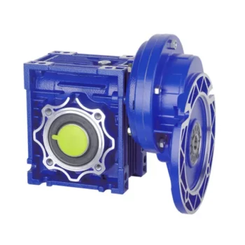
Detailed Photos
RV Series
Including RV / NMRV / NRV.
Main Characteristic of RV Series Worm Gearbox
RV series worm gear reducer is a new-generation product developed by CHINAMFG on the basis of perfecting WJ series products with a compromise of advanced technology both at home and abroad.
1. High-quality aluminum alloy, light in weight and non-rusting.
2. Large in output torque.
3. Smooth running and low noise,durable in dreadful conditions.
4. High radiation efficiency.
5. Good-looking appearance, durable in service life and small volume.
6. Suitable for omnibearing installation.
Main Materials of RV Series Worm Gearbox
1. Housing: die-cast aluminum alloy(frame size: 571 to 090), cast iron(frame size: 110 to 150).
2. Worm: 20Crm, carbonization quencher heat treatment makes the surface hardness of worm gears up to 56-62 HRX, retain carbonization layer's thickness between 0.3 and 0.5mm after precise grinding.
3. Worm Wheel: wearable stannum bronze alloy.
| SPEED RATIO | 7.5~100 |
| OUTPUT TORQUE | <1050NM |
| IN POWER | 0.09-11KW |
| MOUNTING TYPE | FOOT-MOUNTED FLANGE-MOUNTED |
Product Parameters
| When working, great load capacity, stable running, low noise with high efficiency. | |||||||
| Gear Box's Usage Field | |||||||
| 1 | Metallurgy | 11 | Agitator | ||||
| 2 | Mine | 12 | Rotary weeder | ||||
| 3 | Machine | 13 | Metallurgy | ||||
| 4 | Energy | 14 | Compressor | ||||
| 5 | Transmission | 15 | Petroleum industry | ||||
| 6 | Water Conserbancy | 16 | Air Compressor | ||||
| 7 | Tomacco | 17 | Crusher | ||||
| 8 | Medical | 18 | Materials | ||||
| 9 | Packing | 19 | Electronics | ||||
| 10 | Chemical industry | 20 | Textile indutry | ||||
| ... | ... | ||||||
| Power | 0.06kw | 0.09kw | 0.12kw | 0.18kw | 0.25kw | 0.37kw | 0.55kw |
| 0.75kw | 1.1kw | 1.5kw | 2.2kw | 3kw | 4kw | 5.5kw | |
| 7.5kw | 11kw | 15kw | |||||
| Torque | 2.6N.m-3000N.m | ||||||
| Ratio | 7.5-100, the double gearbox is more | ||||||
| Color | Blue, Silver or as customers' need | ||||||
| Material | Iron or Aluminium | ||||||
| Packing | Carton with Plywood Case or as clients' requirement | ||||||
| Type | RV571 | RV030 | RV040 | RV050 | RV063 | RV075 | RV090 |
| Weight | 0.7kg | 1.3kg | 2.3kg | 3.5kg | 6.2kg | 9kg | 13kg |
| Type | RV110 | RV130 | RV150 | ||||
| Weight | 35kg | 60kg | 84kg | ||||
Certifications
Packaging & Shipping
Company Profile
Our Advantages
FAQ
| Application: | Motor, Machinery |
|---|---|
| Hardness: | Hardened Tooth Surface |
| Installation: | Horizontal Type |
| Layout: | Worm |
| Gear Shape: | Worm |
| Step: | Single-Step |
| Customization: |
Available
| Customized Request |
|---|
Maintenance Tips for Prolonging the Life of a Worm Gearbox
Proper maintenance is essential to ensure the longevity and reliable performance of a worm gearbox. Here are some maintenance tips to consider:
- Lubrication: Regularly check and replenish the lubricant in the gearbox. Use the recommended lubricant type and quantity specified by the manufacturer.
- Lubrication Schedule: Follow a lubrication schedule based on the operating conditions and manufacturer recommendations. Regular lubrication prevents friction, reduces wear, and dissipates heat.
- Temperature Monitoring: Keep an eye on the operating temperature of the gearbox. Excessive heat can degrade the lubricant and damage components.
- Cleanliness: Keep the gearbox and surrounding area clean from debris and contaminants. Regularly inspect and clean the gearbox exterior.
- Seal Inspection: Check for any leaks or damage to seals and gaskets. Replace them promptly to prevent lubricant leaks and contamination.
- Alignment: Ensure proper alignment between the worm and worm wheel. Misalignment can lead to increased wear and reduced efficiency.
- Torque Monitoring: Monitor the torque levels during operation. Excessive torque can cause overloading and premature wear.
- Regular Inspections: Periodically inspect all components for signs of wear, damage, or unusual noise. Replace worn or damaged parts promptly.
- Proper Usage: Operate the gearbox within its specified limits, including load, speed, and temperature. Avoid overloading or sudden changes in operating conditions.
- Expert Maintenance: If major maintenance or repairs are needed, consult the manufacturer's guidelines or seek the assistance of qualified technicians.
By following these maintenance tips and adhering to the manufacturer's recommendations, you can extend the lifespan of your worm gearbox and ensure its optimal performance over time.

How to Calculate the Input and Output Speeds of a Worm Gearbox?
Calculating the input and output speeds of a worm gearbox involves understanding the gear ratio and the principles of gear reduction. Here's how you can calculate these speeds:
- Input Speed: The input speed (N1) is the speed of the driving gear, which is the worm gear in this case. It is usually provided by the manufacturer or can be measured directly.
- Output Speed: The output speed (N2) is the speed of the driven gear, which is the worm wheel. To calculate the output speed, use the formula:
N2 = N1 / (Z1 * i)
Where:
N2 = Output speed (rpm)
N1 = Input speed (rpm)
Z1 = Number of teeth on the worm gear
i = Gear ratio (ratio of the number of teeth on the worm gear to the number of threads on the worm)
It's important to note that worm gearboxes are designed for gear reduction, which means that the output speed is lower than the input speed. Additionally, the efficiency of the gearbox, friction, and other factors can affect the actual output speed. Calculating the input and output speeds is crucial for understanding the performance and capabilities of the worm gearbox in a specific application.

Advantages of Using a Worm Reducer in Mechanical Systems
Worm reducers offer several advantages that make them suitable for various mechanical systems:
- High Gear Reduction Ratio: Worm gearboxes provide significant speed reduction, making them ideal for applications that require a high gear reduction ratio without the need for multiple gears.
- Compact Design: Worm reducers have a compact and space-saving design, allowing them to be used in applications with limited space.
- Self-Locking: Worm gearboxes exhibit self-locking properties, which means that the worm screw can prevent the worm wheel from reversing its motion. This is beneficial for applications where the gearbox needs to hold a load in place without external braking mechanisms.
- Smooth and Quiet Operation: Worm gearboxes operate with a sliding motion between the teeth, resulting in smoother and quieter operation compared to some other types of gearboxes.
- High Torque Transmission: Worm gearboxes can transmit high torque levels, making them suitable for applications that require powerful torque output.
- Heat Dissipation: The sliding action between the worm screw and the worm wheel contributes to heat dissipation, which can be advantageous in applications that generate heat during operation.
- Stable Performance: Worm reducers offer stable and reliable performance, making them suitable for continuous operation in various industrial and mechanical systems.
Despite these advantages, it's important to note that worm gearboxes also have limitations, such as lower efficiency compared to other gear types due to the sliding motion and potential for higher heat generation. Therefore, selecting the appropriate type of gearbox depends on the specific requirements and constraints of the application.
editor by CX 2023-09-15