Product Description
Features:
1.Made of high quality aluminium alloy gear reducer,die-cast,non-rusting,convenient to be mounted with worm gearboxes & motors as as to achieve the required speed ratio.
2.Fitting the pre-stage helical module on the main reduction unit is easily done as for any motor of type B14.
3.The PC construction is modular and therefore it can be as a separte unit mounted on any type of fitted geared motor(PAM).
Technical data:
1.Four types manufactured:PC063,PC071,PC080,PC090
2.Speed ratio range:1:2.43---1:3
3.Model: PC063/PC071/PC080/PC090
Quality control
(1) Quality guarantee: 1 year
(2) Certificate of quality: ISO9001:2000
(3) Every product must be tested before sending
| PC | Helical pre-stage unit |
| 080 | Frame size |
| SMRV | Code of worm gear speed reducer |
| 075 | Distance between the centers of worm and worm gear |
| 90 | Speed ratio of worm gear speed reducer |
| E | Double extension worm shaft,no mark means single extension worm shaft |
| F1 | Output flange,no mark means without output flange |
| AZ | "AZ" means bidirectional output shaft, "GZ"means unilateral output shaft and no mark means hole output. |
| B3 | Installation position code |
Note recommendations
To install the reduction unit it is necessary tonote the following recommendations:
1. Check the correct direction of rotation of thereduction unit output shaft before fitting the unit tothe machine.
2. Before mount with the prime moveanddevice,please check the reducers every axiadiameter, aperture,key and key slot,
to be theirdimensions are not deviation, and avoidassembaurtoo tight or too loose, unless it wilinfluence the reducer's performance.
3. The mounting on the machine must be stableto avoid anv vibration.
4.Whenever possible,protect the reductiorunit against solar radiation and bad weather.
5.In the case of particularly lengthy periods ofstorage (4-6 months), if the oil seal is not immersedin the lubricant inside the unit.
It is recommended tochange it since the rubber could stick to the shaft ormay even have lost the elasticity it needs to functionproperly.
6.Painting must definitely not go over rubberparts and the holes on the breather plugs, if any.
7.When connect with hollow or CHINAMFG shaftplease grease the joint to avoid lock or oxidation.
8.Check the correct level of the lubricantthrough the indicator, if there is one.
9. Starting must take place gradually, withoutimmediately applying the maximum load
10. Supporting unit is required when usingvarious of reducer matched with motor directiy andthe wsight of motor is a little bigger than common.
11 .Ensure the motor cools correctly byassuring good passage of air from the fan side.
12. In the case of ambient temperatures+40°C call the Technical Service.
/* March 10, 2571 17:59:20 */!function(){function s(e,r){var a,o={};try{e&&e.split(",").forEach(function(e,t){e&&(a=e.match(/(.*?):(.*)$/))&&1
| Application: | Industry |
|---|---|
| Hardness: | Hardened |
| Manufacturing Method: | Rolling Gear |
| Samples: |
US$ 45/Piece
1 Piece(Min.Order) | Order Sample |
|---|
| Customization: |
Available
| Customized Request |
|---|
.shipping-cost-tm .tm-status-off{background: none;padding:0;color: #1470cc}
|
Shipping Cost:
Estimated freight per unit. |
about shipping cost and estimated delivery time. |
|---|
| Payment Method: |
|
|---|---|
|
Initial Payment Full Payment |
| Currency: | US$ |
|---|
| Return&refunds: | You can apply for a refund up to 30 days after receipt of the products. |
|---|

Can gear reducers be customized for specific industrial needs and requirements?
Yes, gear reducers can be customized to meet specific industrial needs and requirements. Manufacturers offer customization options to ensure that gear reducers are tailored to the unique demands of various applications:
1. Gear Ratio Selection: Gear reducers can be designed with specific gear ratios to achieve the desired speed reduction or increase, catering to the specific requirements of the machinery or equipment.
2. Shaft Configurations: Gear reducers can be configured with different shaft sizes, lengths, and orientations to fit seamlessly into existing systems or accommodate specific mounting arrangements.
3. Torque Capacity: Customized gear reducers can be designed to handle higher or lower torque loads based on the application's operational requirements.
4. Environmental Considerations: Gear reducers can be customized with special coatings, materials, or seals to withstand harsh environments, extreme temperatures, or corrosive conditions.
5. Noise and Vibration Reduction: Custom designs can incorporate features to reduce noise and dampen vibrations, enhancing the overall operation and user experience.
6. Mounting and Connection Options: Manufacturers can adapt gear reducer designs to include specific mounting interfaces or connection methods that align with the equipment's design.
7. Lubrication and Maintenance: Customized gear reducers can include features for easy maintenance, such as accessible lubrication points or monitoring systems.
8. Integration with Controls: Gear reducers can be customized to integrate seamlessly with control systems, sensors, or automation processes, enhancing system efficiency and performance.
By collaborating with manufacturers and providing detailed specifications, industries can obtain tailor-made gear reducers that address their specific operational needs and contribute to the success of their applications.

How do gear reducers handle shock loads and sudden changes in torque?
Gear reducers are designed to handle shock loads and sudden changes in torque through several mechanisms that enhance their durability and reliability in challenging operating conditions.
1. Robust Construction: Gear reducers are constructed using high-strength materials and precision manufacturing techniques. This ensures that the gears, bearings, and other components can withstand sudden impacts and high torque fluctuations without deformation or failure.
2. Shock-Absorbing Features: Some gear reducer designs incorporate shock-absorbing features, such as flexible couplings, elastomeric elements, or torsionally flexible gear designs. These features help dampen and dissipate the energy from sudden shocks or torque spikes, reducing the impact on the entire system.
3. Torque Limiters: In applications where shock loads are common, torque limiters may be integrated into the gear reducer. These devices automatically disengage or slip when a certain torque threshold is exceeded, preventing damage to the gears and other components.
4. Overload Protection: Gear reducers can be equipped with overload protection mechanisms, such as shear pins or torque sensors. These mechanisms detect excessive torque and disengage the drive temporarily, allowing the system to absorb the shock or adjust to the sudden torque change.
5. Proper Lubrication: Adequate lubrication is essential for managing shock loads and sudden torque changes. High-quality lubricants reduce friction and wear, helping the gear reducer withstand dynamic forces and maintain smooth operation.
6. Dynamic Load Distribution: Gear reducers distribute dynamic loads across multiple gear teeth, which helps prevent localized stress concentrations. This feature minimizes the risk of tooth breakage and gear damage when subjected to sudden changes in torque.
By incorporating these design features and mechanisms, gear reducers can effectively handle shock loads and sudden changes in torque, ensuring the longevity and reliability of various industrial and mechanical systems.

What industries and machinery commonly utilize gear reducers?
Gear reducers are widely used across various industries and types of machinery for torque reduction and speed control. Some common industries and applications include:
- 1. Manufacturing: Gear reducers are used in manufacturing equipment such as conveyors, mixers, and packaging machines to control speed and transmit power efficiently.
- 2. Automotive: They are utilized in vehicles for applications like power transmission in transmissions and differentials.
- 3. Aerospace: Gear reducers are used in aircraft systems, including landing gear mechanisms and engine accessories.
- 4. Robotics and Automation: They play a crucial role in robotic arms, CNC machines, and automated production lines.
- 5. Mining and Construction: Gear reducers are used in heavy machinery like excavators, bulldozers, and crushers for power transmission and torque multiplication.
- 6. Energy and Power Generation: Wind turbines, hydroelectric generators, and other power generation equipment use gear reducers to convert rotational speed and transmit power.
- 7. Marine and Shipbuilding: They are used in ship propulsion systems, steering mechanisms, and anchor handling equipment.
- 8. Material Handling: Gear reducers are essential in conveyor systems, elevators, and hoists for controlled movement of materials.
- 9. Food and Beverage: They find applications in food processing equipment like mixers, grinders, and packaging machines.
- 10. Paper and Pulp: Gear reducers are used in machinery for pulp processing, paper production, and printing.
These examples represent just a fraction of the industries and machinery that benefit from the use of gear reducers to optimize power transmission and achieve the desired motion characteristics.


editor by CX 2024-02-02
China OEM Speed Reducer Small Induction Motors Worm Gear Speed Reducer with Electric Motor Reducer with Motor synchromesh gearbox
Product Description
Product Description
Rotary speed reducer/slewing drive
Main fetures:
1.large speed ratio range
2.small volume,low weight ,saving space for mounting.
3.high efficiency,high mechanical strength and high quality aluminum alloy housing
4.long life service,large output torque,low noise and little vibration
5.low temperature rise,omnibearing installation ,easy to connect with other machinery.
6.high carry ability,elegant apperance.
7.CE standard,input power can be 0.06KW-15KW
8.stable transmission
Product Parameters
Detailed Photos
More Models
Packaging & Shipping
Company Profile
/* March 10, 2571 17:59:20 */!function(){function s(e,r){var a,o={};try{e&&e.split(",").forEach(function(e,t){e&&(a=e.match(/(.*?):(.*)$/))&&1
| Application: | Motor, Electric Cars, Motorcycle, Machinery, Marine, Agricultural Machinery, Car |
|---|---|
| Hardness: | Hardened Tooth Surface |
| Layout: | Coaxial |
| Gear Shape: | Bevel / Miter |
| Type: | Planetary Gear Reducer |
| Output Torque: | 0-50 Nm |
| Customization: |
Available
| Customized Request |
|---|

How do gear reducers contribute to energy efficiency in machinery and equipment?
Gear reducers play a significant role in enhancing energy efficiency in various machinery and equipment. Here's how they contribute:
1. Speed Reduction: Gear reducers are commonly used to reduce the speed of the input shaft, allowing the motor to operate at a higher speed where it's most efficient. This speed reduction helps match the motor's optimal operating range, reducing energy consumption.
2. Torque Increase: Gear reducers can increase torque output while decreasing speed, enabling machinery to handle higher loads without the need for a larger, more energy-intensive motor.
3. Matching Load Requirements: By adjusting gear ratios, gear reducers ensure that the machinery's output speed and torque match the load requirements. This prevents the motor from operating at unnecessary high speeds, saving energy.
4. Variable Speed Applications: In applications requiring variable speeds, gear reducers allow for efficient speed control without the need for continuous motor adjustments, improving energy usage.
5. Efficient Power Transmission: Gear reducers efficiently transmit power from the motor to the load, minimizing energy losses due to friction and inefficiencies.
6. Motor Downsizing: Gear reducers enable the use of smaller, more energy-efficient motors by converting their higher speed, lower torque output into the lower speed, higher torque needed for the application.
7. Decoupling Motor and Load Speeds: In cases where the motor and load speeds are inherently different, gear reducers ensure the motor operates at its most efficient speed while still delivering the required output to the load.
8. Overcoming Inertia: Gear reducers help overcome the inertia of heavy loads, making it easier for motors to start and stop, reducing energy consumption during frequent operation.
9. Precise Control: Gear reducers provide precise control over speed and torque, optimizing the energy consumption of machinery in processes that require accurate adjustments.
10. Regenerative Braking: In some applications, gear reducers can be used to capture and convert kinetic energy back into electrical energy during braking or deceleration, improving overall energy efficiency.
By efficiently managing speed, torque, and power transmission, gear reducers contribute to energy-efficient operation, reducing energy consumption, and minimizing the environmental impact of machinery and equipment.
How do gear reducers handle shock loads and sudden changes in torque?
Gear reducers are designed to handle shock loads and sudden changes in torque through several mechanisms that enhance their durability and reliability in challenging operating conditions.
1. Robust Construction: Gear reducers are constructed using high-strength materials and precision manufacturing techniques. This ensures that the gears, bearings, and other components can withstand sudden impacts and high torque fluctuations without deformation or failure.
2. Shock-Absorbing Features: Some gear reducer designs incorporate shock-absorbing features, such as flexible couplings, elastomeric elements, or torsionally flexible gear designs. These features help dampen and dissipate the energy from sudden shocks or torque spikes, reducing the impact on the entire system.
3. Torque Limiters: In applications where shock loads are common, torque limiters may be integrated into the gear reducer. These devices automatically disengage or slip when a certain torque threshold is exceeded, preventing damage to the gears and other components.
4. Overload Protection: Gear reducers can be equipped with overload protection mechanisms, such as shear pins or torque sensors. These mechanisms detect excessive torque and disengage the drive temporarily, allowing the system to absorb the shock or adjust to the sudden torque change.
5. Proper Lubrication: Adequate lubrication is essential for managing shock loads and sudden torque changes. High-quality lubricants reduce friction and wear, helping the gear reducer withstand dynamic forces and maintain smooth operation.
6. Dynamic Load Distribution: Gear reducers distribute dynamic loads across multiple gear teeth, which helps prevent localized stress concentrations. This feature minimizes the risk of tooth breakage and gear damage when subjected to sudden changes in torque.
By incorporating these design features and mechanisms, gear reducers can effectively handle shock loads and sudden changes in torque, ensuring the longevity and reliability of various industrial and mechanical systems.

Are there variations in gear reducer designs for specific tasks and applications?
Yes, gear reducer designs vary widely to suit specific tasks and applications across various industries. Manufacturers offer a range of gear reducer types and configurations to accommodate different requirements, including:
- Helical Gear Reducers: These are versatile and provide smooth and efficient torque transmission. They are commonly used in applications requiring high precision and moderate speed reduction, such as conveyors, mixers, and agitators.
- Bevel Gear Reducers: These are ideal for transmitting power between intersecting shafts. They are often used in heavy machinery, printing presses, and automotive applications.
- Worm Gear Reducers: These provide compact solutions and are suitable for applications with higher speed reduction requirements, such as conveyor systems, winches, and elevators.
- Planetary Gear Reducers: These offer high torque density and are used in applications demanding precise control, such as robotics, aerospace, and heavy-duty machinery.
- Parallel Shaft Gear Reducers: Commonly used in industrial machinery, these reducers are designed for high torque and reliability.
- Right-Angle Gear Reducers: These are used when space limitations require a change in shaft direction, commonly found in packaging equipment and conveyors.
Each type of gear reducer has unique features and benefits that make it suitable for specific tasks. Manufacturers often provide customization options to tailor gear reducers to the precise requirements of an application, including gear ratios, mounting options, and input/output configurations.
Therefore, the variation in gear reducer designs allows industries to select the most appropriate type based on factors such as torque, speed, space constraints, precision, and environmental conditions.
editor by CX 2023-12-21
China Custom Worm Gear Reducers Wp Series Reducer Small Reduction Gearbox Worm Gear Industrial Speed Industrial Transmission Stainless Steel Best Manufacture Worm Reducers planetary gearbox
Product Description
Worm Gear Reducers wp series reducer small reduction gearbox worm gear industrial speed industrial transmission stainless steel best manufacture worm reducer
A worm reducer is a type of reduction gear that is used to convert high motor speed input into lower speed output while also maintaining high torque. The worm producer consists of a gear in the form of a screw meshed into the machine which outputs in the right angle orientation. The worm gearbox is mostly made of bronze with steel or stainless steel worm. The size of the worm reducer is very small and sleek compared to other gear reducers which makes it very handy for rated motor speed and space problems.
Uses of Worm Reducers?
The worm reducers are applied in fields like tuning instruments, elevators, escalators, conveyor belts, medical equipment, power transmission systems, and security CHINAMFG to name a few.
Types of worm gear reducers?
There are 44 series of worm reducers classified according to transmission application.
What is the worm gear reducer used for?
A worm gear (or worm drive) is a specific gear composition in which a screw (worm) meshes with a gear/wheel similar to a spur gear. The set-up allows the user to determine rotational speed and also allows for higher torque to be transmitted.
How does a worm gear work?
How Worm Gears Work. An electric motor or engine applies rotational power via to the worm. The worm rotates against the wheel, and the screw face pushes on the teeth of the wheel. The wheel is pushed against the load.
Can a worm gear go both directions?
Worm drives can go either direction, but they need to be designed for it. As you can imagine, turning the worm shaft under load will create a thrust along the axis of the screw. However, if you reverse the direction the direction of thrust will reverse as well.
How do you find the gear ratio of a worm gear?
Number of Threads in Worms
The number of threads in a worm is the number of teeth in a worm. The speed transmission ratio of a worm and worm gear set is obtained by dividing the number of teeth of the worm gear by the number of threads of the worm.
These are further available in different ratios. The RV reducers are available in the ratios of 5:1 to 100:1. The worm gearboxes are also classified according to their uses and structure, some of them are - Shaft to bore, flange mount, NEMA flange, miniature, high- ratio reduction, compact, and molded glass-filled housing. You can also get it modified according to specific or particular needs.
Benefits of worm gear reducers?
The basic benefit of the worm reducer is that it produces an output of 90 degrees to the input with higher torque and lower speed. In addition to the benefits of high-speed reduction and torque multiplication, the worm gearbox also provides for shock absorption, quiet operation, smaller size, and the adjustable mounting position. This makes the worm reducer the best quality reducer for heavy applications.
| Application: | Motor, Electric Cars, Machinery, Agricultural Machinery |
|---|---|
| Hardness: | Hardened Tooth Surface |
| Installation: | Horizontal Type |
| Layout: | Coaxial |
| Step: | Four-Step |
| Input Speed: | 1450 Rpm |
| Samples: |
US$ 9999/Piece
1 Piece(Min.Order) | |
|---|
Can gear reducers be customized for specific industrial needs and requirements?
Yes, gear reducers can be customized to meet specific industrial needs and requirements. Manufacturers offer customization options to ensure that gear reducers are tailored to the unique demands of various applications:
1. Gear Ratio Selection: Gear reducers can be designed with specific gear ratios to achieve the desired speed reduction or increase, catering to the specific requirements of the machinery or equipment.
2. Shaft Configurations: Gear reducers can be configured with different shaft sizes, lengths, and orientations to fit seamlessly into existing systems or accommodate specific mounting arrangements.
3. Torque Capacity: Customized gear reducers can be designed to handle higher or lower torque loads based on the application's operational requirements.
4. Environmental Considerations: Gear reducers can be customized with special coatings, materials, or seals to withstand harsh environments, extreme temperatures, or corrosive conditions.
5. Noise and Vibration Reduction: Custom designs can incorporate features to reduce noise and dampen vibrations, enhancing the overall operation and user experience.
6. Mounting and Connection Options: Manufacturers can adapt gear reducer designs to include specific mounting interfaces or connection methods that align with the equipment's design.
7. Lubrication and Maintenance: Customized gear reducers can include features for easy maintenance, such as accessible lubrication points or monitoring systems.
8. Integration with Controls: Gear reducers can be customized to integrate seamlessly with control systems, sensors, or automation processes, enhancing system efficiency and performance.
By collaborating with manufacturers and providing detailed specifications, industries can obtain tailor-made gear reducers that address their specific operational needs and contribute to the success of their applications.

What maintenance practices are essential for prolonging the lifespan of gear reducers?
Proper maintenance is crucial for extending the lifespan and ensuring optimal performance of gear reducers. Here are essential maintenance practices:
- 1. Lubrication: Regular lubrication of gear reducers is vital to reduce friction, wear, and heat generation. Use the recommended lubricant and follow the manufacturer's guidelines for lubrication intervals.
- 2. Inspection: Routinely inspect gear reducers for signs of wear, damage, or leaks. Check for unusual noises, vibrations, or temperature increases during operation.
- 3. Alignment: Ensure proper alignment of the input and output shafts. Misalignment can lead to increased wear, noise, and reduced efficiency. Align the components according to the manufacturer's specifications.
- 4. Cooling and Ventilation: Maintain proper cooling and ventilation to prevent overheating. Ensure that cooling fans and vents are clean and unobstructed.
- 5. Seal Maintenance: Inspect and replace seals as needed to prevent contaminants from entering the gear reducer. Contaminants can lead to accelerated wear and reduced performance.
- 6. Bolts and Fasteners: Regularly check and tighten bolts and fasteners to prevent loosening during operation, which can cause misalignment or component damage.
- 7. Replacing Worn Components: Replace worn or damaged components, such as gears, bearings, and seals, with genuine parts from the manufacturer.
- 8. Vibration Analysis: Conduct periodic vibration analysis to identify potential issues early. Excessive vibration can indicate misalignment or component wear.
- 9. Maintenance Records: Keep detailed maintenance records, including lubrication schedules, inspection dates, and component replacements. This helps track the history of the gear reducer and aids in future maintenance planning.
- 10. Training: Provide proper training to maintenance personnel on gear reducer maintenance and troubleshooting techniques.
By adhering to these maintenance practices, you can maximize the lifespan of your gear reducers, minimize downtime, and ensure reliable operation in your industrial processes.
Can you explain the different types of gear reducers available in the market?
There are several types of gear reducers commonly used in industrial applications:
1. Spur Gear Reducers: These reducers have straight teeth and are cost-effective for applications requiring moderate torque and speed reduction. They are efficient but may produce more noise compared to other types.
2. Helical Gear Reducers: Helical gears have angled teeth, which provide smoother and quieter operation compared to spur gears. They offer higher torque capacities and are suitable for heavy-duty applications.
3. Bevel Gear Reducers: Bevel gears have conical shapes and intersect at an angle, allowing them to transmit power between non-parallel shafts. They are commonly used in applications where shafts intersect at 90 degrees.
4. Worm Gear Reducers: Worm gears consist of a worm (screw) and a mating gear (worm wheel). They offer high torque reduction and are used for applications requiring high ratios, although they can be less efficient.
5. Planetary Gear Reducers: These reducers use a system of planetary gears to achieve high torque output in a compact design. They provide excellent torque multiplication and are commonly used in robotics and automation.
6. Cycloidal Gear Reducers: Cycloidal drives use an eccentric cam to achieve speed reduction. They offer high shock load resistance and are suitable for applications with frequent starting and stopping.
7. Harmonic Drive Reducers: Harmonic drives use a flexible spline to achieve high gear reduction ratios. They provide high precision and are commonly used in applications requiring accurate positioning.
8. Hypoid Gear Reducers: Hypoid gears have helical teeth and non-intersecting shafts, making them suitable for applications with space limitations. They offer high torque and efficiency.
Each type of gear reducer has its own advantages and limitations, and the choice depends on factors such as torque requirements, speed ratios, noise levels, space constraints, and application-specific needs.
editor by CX 2023-10-09
China best Worm Gear Reducers Wp Series Reducer Small Reduction Gearbox Worm Gear Industrial Speed Industrial Transmission Stainless Steel Best Manufacture Worm Reducers planetary gearbox
Product Description
Worm Gear Reducers wp series reducer small reduction gearbox worm gear industrial speed industrial transmission stainless steel best manufacture worm reducer
A worm reducer is a type of reduction gear that is used to convert high motor speed input into lower speed output while also maintaining high torque. The worm producer consists of a gear in the form of a screw meshed into the machine which outputs in the right angle orientation. The worm gearbox is mostly made of bronze with steel or stainless steel worm. The size of the worm reducer is very small and sleek compared to other gear reducers which makes it very handy for rated motor speed and space problems.
Uses of Worm Reducers?
The worm reducers are applied in fields like tuning instruments, elevators, escalators, conveyor belts, medical equipment, power transmission systems, and security CHINAMFG to name a few.
Types of worm gear reducers?
There are 44 series of worm reducers classified according to transmission application.
What is the worm gear reducer used for?
A worm gear (or worm drive) is a specific gear composition in which a screw (worm) meshes with a gear/wheel similar to a spur gear. The set-up allows the user to determine rotational speed and also allows for higher torque to be transmitted.
How does a worm gear work?
How Worm Gears Work. An electric motor or engine applies rotational power via to the worm. The worm rotates against the wheel, and the screw face pushes on the teeth of the wheel. The wheel is pushed against the load.
Can a worm gear go both directions?
Worm drives can go either direction, but they need to be designed for it. As you can imagine, turning the worm shaft under load will create a thrust along the axis of the screw. However, if you reverse the direction the direction of thrust will reverse as well.
How do you find the gear ratio of a worm gear?
Number of Threads in Worms
The number of threads in a worm is the number of teeth in a worm. The speed transmission ratio of a worm and worm gear set is obtained by dividing the number of teeth of the worm gear by the number of threads of the worm.
These are further available in different ratios. The RV reducers are available in the ratios of 5:1 to 100:1. The worm gearboxes are also classified according to their uses and structure, some of them are - Shaft to bore, flange mount, NEMA flange, miniature, high- ratio reduction, compact, and molded glass-filled housing. You can also get it modified according to specific or particular needs.
Benefits of worm gear reducers?
The basic benefit of the worm reducer is that it produces an output of 90 degrees to the input with higher torque and lower speed. In addition to the benefits of high-speed reduction and torque multiplication, the worm gearbox also provides for shock absorption, quiet operation, smaller size, and the adjustable mounting position. This makes the worm reducer the best quality reducer for heavy applications.
| Application: | Motor, Electric Cars, Machinery, Agricultural Machinery |
|---|---|
| Hardness: | Hardened Tooth Surface |
| Installation: | Horizontal Type |
| Layout: | Coaxial |
| Step: | Four-Step |
| Input Speed: | 1450 Rpm |
| Samples: |
US$ 9999/Piece
1 Piece(Min.Order) | |
|---|

How do gear reducers enhance the efficiency of conveyor systems and robotics?
Gear reducers play a significant role in improving the efficiency of both conveyor systems and robotics by optimizing speed, torque, and control. Here's how they contribute:
Conveyor Systems:
In conveyor systems, gear reducers enhance efficiency in the following ways:
- Speed Control: Gear reducers allow precise control over the rotational speed of conveyor belts, ensuring that materials are transported at the desired speed for efficient production processes.
- Torque Adjustment: By adjusting gear ratios, gear reducers provide the necessary torque to handle varying loads and prevent overloading, minimizing energy wastage.
- Reverse Operation: Gear reducers enable smooth bidirectional movement of conveyor belts, facilitating tasks such as loading, unloading, and distribution without the need for additional components.
- Synchronization: Gear reducers ensure synchronized movement of multiple conveyor belts in complex systems, optimizing material flow and minimizing jams or bottlenecks.
Robotics:
In robotics, gear reducers enhance efficiency through the following means:
- Precision Movement: Gear reducers provide precise control over the movement of robot joints and arms, enabling accurate positioning and manipulation of objects.
- Reduced Inertia: Gear reducers help reduce the inertia experienced by robotic components, allowing for quicker and more responsive movements while conserving energy.
- Compact Design: Gear reducers offer a compact and lightweight solution for achieving various motion profiles in robotic systems, allowing for efficient use of space and resources.
- Torque Amplification: By amplifying torque from the motor, gear reducers enable robots to handle heavier loads and perform tasks that require greater force, enhancing their overall capabilities.
By providing precise speed control, torque adjustment, and reliable motion transmission, gear reducers optimize the performance of conveyor systems and robotics, leading to improved efficiency, reduced energy consumption, and enhanced operational capabilities.
What maintenance practices are essential for prolonging the lifespan of gear reducers?
Proper maintenance is crucial for extending the lifespan and ensuring optimal performance of gear reducers. Here are essential maintenance practices:
- 1. Lubrication: Regular lubrication of gear reducers is vital to reduce friction, wear, and heat generation. Use the recommended lubricant and follow the manufacturer's guidelines for lubrication intervals.
- 2. Inspection: Routinely inspect gear reducers for signs of wear, damage, or leaks. Check for unusual noises, vibrations, or temperature increases during operation.
- 3. Alignment: Ensure proper alignment of the input and output shafts. Misalignment can lead to increased wear, noise, and reduced efficiency. Align the components according to the manufacturer's specifications.
- 4. Cooling and Ventilation: Maintain proper cooling and ventilation to prevent overheating. Ensure that cooling fans and vents are clean and unobstructed.
- 5. Seal Maintenance: Inspect and replace seals as needed to prevent contaminants from entering the gear reducer. Contaminants can lead to accelerated wear and reduced performance.
- 6. Bolts and Fasteners: Regularly check and tighten bolts and fasteners to prevent loosening during operation, which can cause misalignment or component damage.
- 7. Replacing Worn Components: Replace worn or damaged components, such as gears, bearings, and seals, with genuine parts from the manufacturer.
- 8. Vibration Analysis: Conduct periodic vibration analysis to identify potential issues early. Excessive vibration can indicate misalignment or component wear.
- 9. Maintenance Records: Keep detailed maintenance records, including lubrication schedules, inspection dates, and component replacements. This helps track the history of the gear reducer and aids in future maintenance planning.
- 10. Training: Provide proper training to maintenance personnel on gear reducer maintenance and troubleshooting techniques.
By adhering to these maintenance practices, you can maximize the lifespan of your gear reducers, minimize downtime, and ensure reliable operation in your industrial processes.
How do gear reducers contribute to speed reduction and torque increase?
Gear reducers play a crucial role in mechanical systems by achieving speed reduction and torque increase through the principle of gear ratios. Here's how they work:
Gear reducers consist of multiple gears with different sizes, known as gear pairs. These gears are meshed together, and their teeth interlock to transmit motion and power. The gear ratio is determined by the ratio of the number of teeth on the input gear (driver) to the number of teeth on the output gear (driven).
Speed Reduction: When a larger gear (output gear) is driven by a smaller gear (input gear), the output gear rotates at a slower speed than the input gear. This reduction in speed is proportional to the gear ratio. As a result, gear reducers are used to slow down the rotational speed of the output shaft compared to the input shaft.
Torque Increase: The interlocking teeth of gears create a mechanical advantage that allows gear reducers to increase torque output. When the input gear applies a force (torque) to the teeth, it is transmitted to the output gear with greater force due to the leverage provided by the larger diameter of the output gear. The torque increase is inversely proportional to the gear ratio and is essential for applications requiring high torque at lower speeds.
By selecting appropriate gear ratios and arranging gear pairs, gear reducers can achieve various speed reduction and torque multiplication factors, making them essential components in machinery and equipment where precise control of speed and torque is necessary.
editor by CX 2023-10-08
China Professional Speed Small Gear Box Planetary Reducer Gearbox for Servo Motor synchromesh gearbox
Product Description
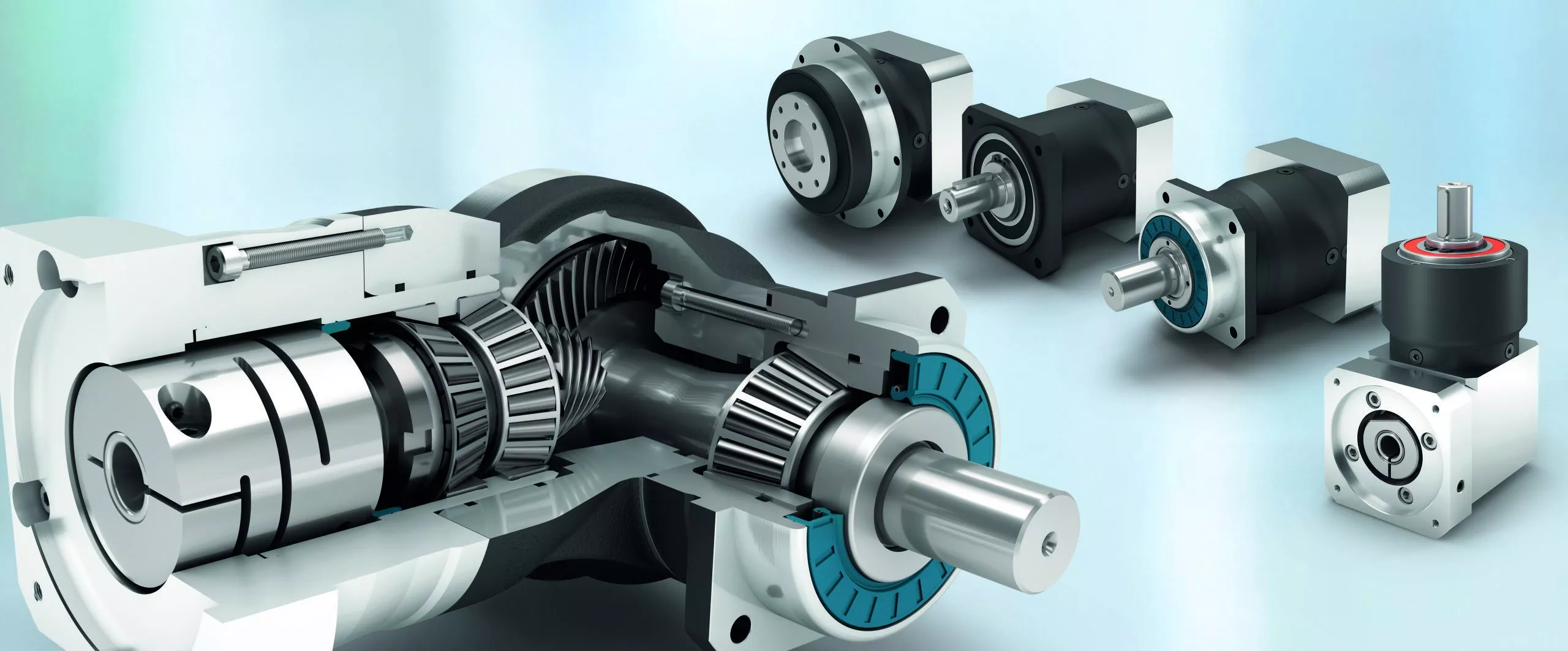
Planetary Gearbox AB Series Square Flange Helical Bevel Planetary Transmission Gearboxes Servo Motor
PLF series, PLE series, ZPLF series, ZPLE series, AB series, ABR series and many other models are available.
Product Description
Planetary Gearbox AB Series Square Flange Helical Bevel Planetary Transmission Gearboxes Servo Motor
Advantages of the planetary gearbox:
Low backlash
High Efficiency
High Torque
High Input Speed
High Stability
High Reduction Ratio
Detailed Photos
Product Parameters
|
Name |
High Precision Planetary Gearbox |
|
Model |
AB042, AB060, AB060A, AB090A, AB115, AB142, AB180, AB220 |
|
Gearing Arrangement |
Planetary |
|
Effeiency withfull load |
≥97 |
|
Backlash |
≤5 |
|
Weight |
0.5~48kg |
|
Gear Type |
Helical Gear |
|
Gear stages |
1 stage, 2 stage |
|
Rated Torque |
14N.m-2000N.m |
|
Gear Ratio One-stage |
3, 4, 5, 6, 7, 8, 9, 10 |
|
Gear Ratio Two-stage |
15, 20, 25, 30, 35, 40, 45, 50, 60, 70, 80, 90, 100 |
|
Mounting Position |
Horizontal (foot mounted) or Vertical (flange mounted) |
|
Usage |
stepper motor, servo motor, AC motor, DC motor, etc |
External Mounting Dimensions
1 stage reduction ratio 3~10
2 stage reduction ratio 15~100
Applications
Product Overview:
Precision planetary gear reducer is another name for planetary gear reducer in the industry. Its main transmission structure is planetary gear, sun gear and inner gear ring.
Compared with other gear reducers, precision planetary gear reducers have the characteristics of high rigidity, high precision (single stage can achieve less than 1 point), high transmission efficiency (single stage can achieve 97% - 98%), high torque/volume ratio, lifelong maintenance-free, etc. Most of them are installed on stepper motor and servo motor to reduce speed, improve torque and match inertia.
| Hardness: | Hardened Tooth Surface |
|---|---|
| Installation: | Vertical Type |
| Layout: | Coaxial |
| Gear Shape: | Planetary |
| Step: | Single-Step |
| Type: | Ab Series Gearbox, Gear Reducer |
| Samples: |
US$ 100/Piece
1 Piece(Min.Order) | |
|---|
Handling Sudden Changes in Direction and Speed with Servo Gearboxes
Servo gearboxes are designed to handle sudden changes in direction and speed effectively, ensuring precise motion control even during dynamic operations. They employ several mechanisms to address these challenges:
1. Acceleration and Deceleration Profiles: Servo systems can be programmed with specific acceleration and deceleration profiles. This means that when a sudden change in speed or direction is commanded, the system can ramp up or down the speed smoothly, reducing the impact of sudden changes on the mechanical components.
2. Closed-Loop Control: Servo systems operate in a closed-loop configuration, where feedback sensors continuously monitor the actual position and speed of the system. When a sudden change is commanded, the controller can make real-time adjustments to ensure the system reaches the desired position accurately and smoothly.
3. Torque Control: Servo gearboxes are designed to provide high torque output even at low speeds. This is crucial for handling sudden changes in direction and speed, as the gearbox can deliver the required torque to quickly accelerate or decelerate the load.
4. Dynamic Response: Servo systems have fast dynamic response capabilities, which means they can quickly adapt to changes in input commands. This responsiveness allows the system to handle sudden changes in direction and speed without sacrificing accuracy or stability.
5. Electronic Damping: Some advanced servo systems incorporate electronic damping mechanisms that can be adjusted based on the application's requirements. This feature helps dampen vibrations and oscillations that may occur during sudden changes in motion.
6. Overcurrent and Overvoltage Protection: Servo systems are equipped with protection mechanisms that detect excessive currents or voltages. If a sudden change in direction or speed causes abnormal loads or voltages, the system can take corrective actions to prevent damage.
Overall, servo gearboxes excel in handling sudden changes in direction and speed by leveraging their closed-loop control, high torque output, and fast dynamic response capabilities. These features allow them to provide accurate and reliable motion control in dynamic and rapidly changing operating conditions.

Considerations for Selecting the Right Servo Gearbox for an Application
Choosing the appropriate servo gearbox for a specific application requires careful evaluation of several key factors:
1. Torque and Speed Requirements: Determine the required torque and speed characteristics of the application, ensuring that the chosen servo gearbox can provide the necessary output.
2. Gear Ratio: Calculate the ideal gear ratio based on the desired motion profile, acceleration, and deceleration requirements.
3. Mounting and Integration: Consider the available space and mechanical layout of the machinery to choose a servo gearbox with the appropriate mounting configuration.
4. Motor Compatibility: Ensure that the servo gearbox is compatible with the specific type and size of motor being used for the application.
5. Precision and Accuracy: Evaluate the level of precision required for the application's motion control. Choose a servo gearbox that can deliver the necessary accuracy and repeatability.
6. Load Distribution: Analyze how the load will be distributed among the gears to prevent excessive wear and ensure optimal performance.
7. Backlash and Compliance: Consider the application's tolerance for backlash and compliance. Choose a servo gearbox with low backlash if precise positioning is essential.
8. Environmental Conditions: Factor in the environmental conditions of the application, such as temperature, humidity, and exposure to contaminants. Choose a servo gearbox with suitable sealing and protection.
9. Lubrication: Determine the lubrication requirements of the gearbox and select a model that aligns with the application's maintenance practices.
10. Overload and Shock: Consider potential overload and shock conditions the gearbox may experience. Choose a servo gearbox that can handle sudden changes in load without compromising performance.
11. Feedback Devices: If precise motion control is required, choose a servo gearbox that is compatible with the desired feedback devices, such as encoders or resolvers.
12. Efficiency: Evaluate the efficiency of the servo gearbox to ensure that it contributes to the overall energy efficiency of the system.
13. Service and Support: Select a reputable manufacturer that offers reliable technical support, documentation, and post-purchase services.
14. Budget: Balance the performance requirements of the application with the available budget to make an informed decision.
By carefully considering these factors, engineers and designers can confidently choose the right servo gearbox that meets the specific needs of their application, optimizing performance and productivity.

Role of Servo Gearbox in Robotics and Automation
Servo gearboxes play a crucial role in enhancing the performance and precision of robotics and automation systems:
1. Precision Motion Control: In robotics and automation, precise control of movement is essential. Servo gearboxes provide accurate speed and position control, allowing robots to perform intricate tasks with high accuracy.
2. Efficient Power Transmission: Servo gearboxes efficiently transmit power from the motor to the robotic components, ensuring minimal energy loss and optimizing the overall system efficiency.
3. Dynamic Performance: Robots often require quick changes in direction, speed, and acceleration. Servo gearboxes excel in dynamic performance, enabling rapid adjustments and smooth motion changes.
4. Reducing Backlash: Backlash in gear systems can lead to imprecise movements. Servo gearboxes are designed to minimize backlash, resulting in accurate positioning and reduced lost motion.
5. Compact Design: Many robotic applications require compact and lightweight components. Servo gearboxes offer a high torque-to-size ratio, allowing robots to generate significant power while maintaining a small footprint.
6. Smooth and Silent Operation: The low backlash and precise gearing of servo gearboxes contribute to smooth and quiet operation, which is crucial in environments where noise and vibration can affect performance.
7. Feedback Integration: Servo gearboxes can integrate with various feedback devices, such as encoders, resolvers, and sensors, to provide accurate position and speed information to the control system.
8. Reliable and Repeatable Performance: The consistent and repeatable performance of servo gearboxes ensures that robots can execute tasks accurately and reliably over time.
9. Customization: Servo gearboxes can be customized to meet the specific requirements of different robotic applications, including factors like gear ratios, mounting options, and feedback compatibility.
10. Versatility: From industrial assembly lines to medical robotics, servo gearboxes find applications in a wide range of industries, contributing to improved automation and efficiency.
In summary, the role of a servo gearbox in robotics and automation is to provide the precise and efficient motion control necessary for robots to perform tasks with accuracy, speed, and reliability.
editor by CX 2023-10-08
China best Small Harmonic Drive Gear Reducer with Good quality
Product Description
Product Description:
1. Flexspline is a hollow flanging standard cylinder structure.
2. There is a large-diameter hollow shaft hole in the middle of the cam of the wave generator. The internal design of the reducer has a support bearing.
3. It has a fully sealed structure and is easy to install. It is very suitable for occasions where the wire needs to be threaded from the center of the reducer.
Advantages:
1. High precision,high torque
2. Dedicated technical personnel can be on-the-go to provide design solutions
3. Factory direct sales fine workmanship durable quality assurance
4. Product quality issues have a one-year warranty time, can be returned for replacement or repair
Company profile:
HangZhou CHINAMFG Technology Co., Ltd. established in 2014, is committed to the R & D plant of high-precision transmission components. At present, the annual production capacity can reach 45000 sets of harmonic reducers. We firmly believe in quality first. All links from raw materials to finished products are strictly supervised and controlled, which provides a CHINAMFG foundation for product quality. Our products are sold all over the country and abroad.
The harmonic reducer and other high-precision transmission components were independently developed by the company. Our company spends 20% of its sales every year on the research and development of new technologies in the industry. There are 5 people in R & D.
Our advantage is as below:
1.7 years of marketing experience
2. 5-person R & D team to provide you with technical support
3. It is sold at home and abroad and exported to Turkey and Ireland
4. The product quality is guaranteed with a one-year warranty
5. Products can be customized
Strength factory:
Our plant has an entire campus The number of workshops is around 300 Whether it's from the production of raw materials and the procurement of raw materials to the inspection of finished products, we're doing it ourselves. There is a complete production system
HST-III Parameter:
| Model | Speed ratio | Enter the rated torque at 2000r/min | Allowed CHINAMFG torque at start stop | The allowable maximum of the average load torque | Maximum torque is allowed in an instant | Allow the maximum speed to be entered | Average input speed is allowed | Back gap | design life | ||||
| NM | kgfm | NM | kgfm | NM | kgfm | NM | kgfm | r / min | r / min | Arc sec | Hour | ||
| 14 | 50 | 6.2 | 0.6 | 20.7 | 2.1 | 7.9 | 0.7 | 40.3 | 4.1 | 7000 | 3000 | ≤30 | 10000 |
| 80 | 9 | 0.9 | 27 | 2.7 | 12.7 | 1.3 | 54.1 | 5.5 | |||||
| 100 | 9 | 0.9 | 32 | 3.3 | 12.7 | 1.3 | 62.1 | 6.3 | |||||
| 17 | 50 | 18.4 | 1.9 | 39 | 4 | 29.9 | 3 | 80.5 | 8.2 | 6500 | 3000 | ≤30 | 15000 |
| 80 | 25.3 | 2.6 | 49.5 | 5 | 31 | 3.2 | 100.1 | 10.2 | |||||
| 100 | 27.6 | 2.8 | 62 | 6.3 | 45 | 4.6 | 124.2 | 12.7 | |||||
| 20 | 50 | 28.8 | 2.9 | 64.4 | 6.6 | 39 | 4 | 112.7 | 11.5 | 5600 | 3000 | ≤30 | 15000 |
| 80 | 39.1 | 4 | 85 | 8.8 | 54 | 5.5 | 146.1 | 14.9 | |||||
| 100 | 46 | 4.7 | 94.3 | 9.6 | 56 | 5.8 | 169.1 | 17.2 | |||||
| 120 | 46 | 4.7 | 100 | 10.2 | 56 | 5.8 | 169.1 | 17.2 | |||||
| 160 | 46 | 4.7 | 100 | 10.2 | 56 | 5.8 | 169.1 | 17.2 | |||||
| 25 | 50 | 44.9 | 4.6 | 113 | 11.5 | 63 | 6.5 | 213.9 | 21.8 | 4800 | 3000 | ≤30 | 15000 |
| 80 | 72.5 | 7.4 | 158 | 16.1 | 100 | 10.2 | 293.3 | 29.9 | |||||
| 100 | 77.1 | 7.9 | 181 | 18.4 | 124 | 12.7 | 326.6 | 33.3 | |||||
| 120 | 77.1 | 7.9 | 192 | 19.6 | 124 | 12.7 | 349.6 | 35.6 | |||||
| 32 | 50 | 87.4 | 8.9 | 248 | 25.3 | 124 | 12.7 | 439 | 44.8 | 4000 | 3000 | ≤30 | 15000 |
| 80 | 135.7 | 13.8 | 350 | 35.6 | 192 | 19.6 | 653 | 66.6 | |||||
| 100 | 157.6 | 16.1 | 383 | 39.1 | 248 | 25.3 | 744 | 75.9 | |||||
| 40 | 100 | 308 | 37.2 | 660 | 67 | 432 | 44 | 1232 | 126.7 | 4000 | 3000 | ≤30 | 15000 |
HSG Parameter:
| Model | Speed ratio | Enter the rated torque at 2000r/min | Allowed CHINAMFG torque at start stop | The allowable maximum of the average load torque | Maximum torque is allowed in an instant | Allow the maximum speed to be entered | Average input speed is allowed | Back gap | design life | ||||
| NM | kgfm | NM | kgfm | NM | kgfm | NM | kgfm | r / min | r / min | Arc sec | Hour | ||
| 14 | 50 | 7 | 0.7 | 23 | 2.3 | 9 | 0.9 | 46 | 4.7 | 14000 | 8500 | ≤20 | 15000 |
| 80 | 10 | 1 | 30 | 3.1 | 14 | 1.4 | 61 | 6.2 | |||||
| 100 | 10 | 1 | 36 | 3.7 | 14 | 1.4 | 70 | 7.2 | |||||
| 17 | 50 | 21 | 2.1 | 44 | 4.5 | 34 | 3.4 | 91 | 9 | 10000 | 7300 | ≤20 | 20000 |
| 80 | 29 | 2.9 | 56 | 5.7 | 35 | 3.6 | 113 | 12 | |||||
| 100 | 31 | 3.2 | 70 | 7.2 | 51 | 5.2 | 143 | 15 | |||||
| 20 | 50 | 33 | 3.3 | 73 | 7.4 | 44 | 4.5 | 127 | 13 | 10000 | 6500 | ≤20 | 20000 |
| 80 | 44 | 4.5 | 96 | 9.8 | 61 | 6.2 | 165 | 17 | |||||
| 100 | 52 | 5.3 | 107 | 10.9 | 64 | 6.5 | 191 | 20 | |||||
| 120 | 52 | 5.3 | 113 | 11.5 | 64 | 6.5 | 191 | 20 | |||||
| 160 | 52 | 5.3 | 120 | 12.2 | 64 | 6.5 | 191 | 20 | |||||
| 25 | 50 | 51 | 5.2 | 127 | 13 | 72 | 7.3 | 242 | 25 | 7500 | 5600 | ≤20 | 20000 |
| 80 | 82 | 8.4 | 178 | 18 | 113 | 12 | 332 | 34 | |||||
| 100 | 87 | 8.9 | 204 | 21 | 140 | 14 | 369 | 38 | |||||
| 120 | 87 | 8.9 | 217 | 22 | 140 | 14 | 395 | 40 | |||||
| 32 | 50 | 99 | 10 | 281 | 29 | 140 | 14 | 497 | 51 | 7000 | 4800 | ≤20 | 20000 |
| 80 | 153 | 16 | 395 | 40 | 217 | 22 | 738 | 75 | |||||
| 100 | 178 | 18 | 433 | 44 | 281 | 29 | 841 | 86 | |||||
| 40 | 100 | 345 | 35 | 738 | 75 | 484 | 49 | 1400 | 143 | 5600 | 4000 | ≤20 | 20000 |
Exhibitions:
Application case:
FQA:
Q: What should I provide when I choose a gearbox/speed reducer?
A: The best way is to provide the motor drawing with parameters. Our engineer will check and recommend the most suitable gearbox model for your reference.
Or you can also provide the below specification as well:
1) Type, model, and torque.
2) Ratio or output speed
3) Working condition and connection method
4) Quality and installed machine name
5) Input mode and input speed
6) Motor brand model or flange and motor shaft size
| Application: | Motor, Machinery, Agricultural Machinery, Hst-I |
|---|---|
| Hardness: | Hardened Tooth Surface |
| Installation: | 90 Degree |
| Layout: | Coaxial |
| Gear Shape: | Cylindrical Gear |
| Step: | Single-Step |
| Samples: |
US$ 100/Piece
1 Piece(Min.Order) | |
|---|
| Customization: |
Available
| Customized Request |
|---|

Are there any disadvantages or limitations to using gear reducer systems?
While gear reducer systems offer numerous advantages, they also come with certain disadvantages and limitations that should be considered during the selection and implementation process:
1. Size and Weight: Gear reducers can be bulky and heavy, especially for applications requiring high gear ratios. This can impact the overall size and weight of the machinery or equipment, which may be a concern in space-constrained environments.
2. Efficiency Loss: Despite their high efficiency, gear reducers can experience energy losses due to friction between gear teeth and other components. This can lead to a reduction in overall system efficiency, particularly in cases where multiple gear stages are used.
3. Cost: The design, manufacturing, and assembly of gear reducers can involve complex processes and precision machining, which can contribute to higher initial costs compared to other power transmission solutions.
4. Maintenance: Gear reducer systems require regular maintenance, including lubrication, inspection, and potential gear replacement over time. Maintenance activities can lead to downtime and associated costs in industrial settings.
5. Noise and Vibration: Gear reducers can generate noise and vibrations, especially at high speeds or when operating under heavy loads. Additional measures may be needed to mitigate noise and vibration issues.
6. Limited Gear Ratios: While gear reducers offer a wide range of gear ratios, there may be limitations in achieving extremely high or low ratios in certain designs.
7. Temperature Sensitivity: Extreme temperatures can affect the performance of gear reducer systems, particularly if inadequate lubrication or cooling is provided.
8. Shock Loads: While gear reducers are designed to handle shock loads to some extent, severe shock loads or abrupt changes in torque can still lead to potential damage or premature wear.
Despite these limitations, gear reducer systems remain widely used and versatile components in various industries, and their disadvantages can often be mitigated through proper design, selection, and maintenance practices.
What maintenance practices are essential for prolonging the lifespan of gear reducers?
Proper maintenance is crucial for extending the lifespan and ensuring optimal performance of gear reducers. Here are essential maintenance practices:
- 1. Lubrication: Regular lubrication of gear reducers is vital to reduce friction, wear, and heat generation. Use the recommended lubricant and follow the manufacturer's guidelines for lubrication intervals.
- 2. Inspection: Routinely inspect gear reducers for signs of wear, damage, or leaks. Check for unusual noises, vibrations, or temperature increases during operation.
- 3. Alignment: Ensure proper alignment of the input and output shafts. Misalignment can lead to increased wear, noise, and reduced efficiency. Align the components according to the manufacturer's specifications.
- 4. Cooling and Ventilation: Maintain proper cooling and ventilation to prevent overheating. Ensure that cooling fans and vents are clean and unobstructed.
- 5. Seal Maintenance: Inspect and replace seals as needed to prevent contaminants from entering the gear reducer. Contaminants can lead to accelerated wear and reduced performance.
- 6. Bolts and Fasteners: Regularly check and tighten bolts and fasteners to prevent loosening during operation, which can cause misalignment or component damage.
- 7. Replacing Worn Components: Replace worn or damaged components, such as gears, bearings, and seals, with genuine parts from the manufacturer.
- 8. Vibration Analysis: Conduct periodic vibration analysis to identify potential issues early. Excessive vibration can indicate misalignment or component wear.
- 9. Maintenance Records: Keep detailed maintenance records, including lubrication schedules, inspection dates, and component replacements. This helps track the history of the gear reducer and aids in future maintenance planning.
- 10. Training: Provide proper training to maintenance personnel on gear reducer maintenance and troubleshooting techniques.
By adhering to these maintenance practices, you can maximize the lifespan of your gear reducers, minimize downtime, and ensure reliable operation in your industrial processes.

Function of Gear Reducers in Mechanical Systems
A gear reducer, also known as a gear reduction unit or gearbox, is a mechanical device designed to reduce the speed of an input shaft while increasing its torque output. It accomplishes this through the use of a set of interlocking gears with different sizes.
The primary function of a gear reducer in mechanical systems is to:
- Speed Reduction: The gear reducer takes the high-speed rotation of the input shaft and transmits it to the output shaft through a set of gears. The gears are configured in such a way that the output gear has a larger diameter than the input gear. As a result, the output shaft rotates at a lower speed than the input shaft, but with increased torque.
- Torque Increase: Due to the size difference between the input and output gears, the torque applied to the output shaft is greater than that of the input shaft. This torque multiplication allows the system to handle heavier loads and perform tasks requiring higher force.
Gear reducers are widely used in various industries and applications where it's necessary to adapt the speed and torque characteristics of a power source to meet the requirements of the driven equipment. They can be found in machinery such as conveyor systems, industrial machinery, vehicles, and more.
editor by CX 2023-09-23
China Good quality Mini Vf Series Vf30 Vf40 Vf50 Vf63 Vf75 Transmission Aluminum Alloy Small Worm Gear Speed Reducer Gearbox planetary gearbox
Product Description
VF SERIES WORM GEAR SPEED REDUCER
According to European standard of similar product,we adopt high-quality artificial oil,imported famous brand seal parts and
manufacture technology to produce square multi-placed reductor. Feature beautiful appearance,easy installation,compact
structure,low noise and high efficiency.
Power: 0.04-15 Kw
Transmission Ration Range: 7-100
Output Torque: 24-2700 N.m
Models:
VF Type: VF30, VF44, VF49, VF63, VF72, VF86, VF110, VF130, VF150
VFR Type: VFR44, VFR49, VFR63, VFR72, VFR86, VFR110, VFR30, VFR150
VF-VF Combined Type: VF/VF 30/40, VF/VF 30/49, VF/VF 30/63, VF/VF 44/72, VF/VF 44/86, VF/VF 49/110, VF/VF 63/130, VF/VF 86/150
Application:
This product is widely applied to fields of metallurgy, mines, hoisting, transportation, cement, architecture, chemical, textile, printing, dyeing and pharmaceutical etc.
More mounting position and dimensions please click here to contact us.
Related Products
Company Information
| Application: | Motor, Electric Cars, Motorcycle, Machinery, Marine, Agricultural Machinery, Car |
|---|---|
| Function: | Distribution Power, Clutch, Change Drive Torque, Change Drive Direction, Speed Changing, Speed Reduction, Speed Increase |
| Layout: | Coaxial |
| Hardness: | Hardened Tooth Surface |
| Installation: | Horizontal Type |
| Step: | Steel |
| Samples: |
US$ 9999/Piece
1 Piece(Min.Order) | |
|---|

Is it Possible to Reverse the Direction of a Worm Gearbox?
Yes, it is possible to reverse the direction of a worm gearbox by changing the orientation of either the input or output shaft. However, reversing the direction of a worm gearbox can have some implications that need to be considered:
- Efficiency: Reversing the direction of a worm gearbox can potentially affect its efficiency. Worm gearboxes are typically more efficient in one direction of rotation due to the design of the worm and worm wheel.
- Backlash: Reversing the direction of rotation might lead to increased backlash or play in the gearbox, which can impact precision and smooth operation.
- Lubrication: Depending on the gearbox's design, reversing the direction could affect lubrication distribution and lead to uneven wear on the gear teeth.
- Load: Reversing the direction might also impact the gearbox's load-carrying capacity, especially if it's designed for predominantly one-way operation.
- Noise and Vibration: Direction reversal can sometimes result in increased noise and vibration due to changes in gear engagement and meshing behavior.
If you need to reverse the direction of a worm gearbox, it's advisable to consult the gearbox manufacturer's guidelines and recommendations. They can provide insights into whether the specific gearbox model is suitable for reversible operation and any precautions or adjustments needed to ensure proper functioning.

Materials Used for Worm Gears
Worm gears are manufactured using a variety of materials to meet different application requirements. Some commonly used materials for worm gears include:
- Steel: Steel is a popular choice for worm gears due to its strength, durability, and wear resistance. It can handle heavy loads and is often used in industrial applications.
- Bronze: Bronze offers good lubricity and is commonly used for the worm gear (worm) component. It provides effective wear resistance and works well in applications where quiet operation is essential.
- Cast Iron: Cast iron is known for its high strength and durability. It's often used for worm gears in applications where shock loads or heavy-duty conditions are expected.
- Aluminum: Aluminum worm gears are lightweight and corrosion-resistant, making them suitable for applications where weight reduction is important.
- Plastic: Some worm gears are made from plastic materials such as nylon or acetal. These materials are often chosen for their self-lubricating properties and quiet operation.
- Composite Materials: Composite materials can offer a combination of properties, such as lightweight construction and corrosion resistance. They can be suitable for specific applications.
The choice of material depends on factors such as the application's load, speed, operating environment, and required performance characteristics. It's important to consider these factors when selecting the appropriate material for worm gears to ensure optimal performance and longevity.

Advantages of Using a Worm Reducer in Mechanical Systems
Worm reducers offer several advantages that make them suitable for various mechanical systems:
- High Gear Reduction Ratio: Worm gearboxes provide significant speed reduction, making them ideal for applications that require a high gear reduction ratio without the need for multiple gears.
- Compact Design: Worm reducers have a compact and space-saving design, allowing them to be used in applications with limited space.
- Self-Locking: Worm gearboxes exhibit self-locking properties, which means that the worm screw can prevent the worm wheel from reversing its motion. This is beneficial for applications where the gearbox needs to hold a load in place without external braking mechanisms.
- Smooth and Quiet Operation: Worm gearboxes operate with a sliding motion between the teeth, resulting in smoother and quieter operation compared to some other types of gearboxes.
- High Torque Transmission: Worm gearboxes can transmit high torque levels, making them suitable for applications that require powerful torque output.
- Heat Dissipation: The sliding action between the worm screw and the worm wheel contributes to heat dissipation, which can be advantageous in applications that generate heat during operation.
- Stable Performance: Worm reducers offer stable and reliable performance, making them suitable for continuous operation in various industrial and mechanical systems.
Despite these advantages, it's important to note that worm gearboxes also have limitations, such as lower efficiency compared to other gear types due to the sliding motion and potential for higher heat generation. Therefore, selecting the appropriate type of gearbox depends on the specific requirements and constraints of the application.
editor by CX 2023-09-18
China wholesaler Wpa Worm Gear Reducer Small Gearbox Large Turbine Transmission Vertical Wpo Stirring Horizontal Transmission Parts with Hot selling
Product Description
Wpa Worm Gear Reducer Small Gearbox Large Turbine Transmission Vertical Wpo Stirring Horizontal Transmission Parts
| Application: | Motor, Electric Cars, Motorcycle, Machinery, Marine, Toy, Agricultural Machinery, Car |
|---|---|
| Hardness: | Soft Tooth Surface |
| Installation: | 90 Degree |
| Layout: | Coaxial |
| Gear Shape: | Conical - Cylindrical Gear |
| Step: | Stepless |
| Samples: |
US$ 9999/Piece
1 Piece(Min.Order) | |
|---|

Calculating Gear Ratio in a Worm Reducer
The gear ratio in a worm reducer is determined by the number of teeth on the worm wheel (also known as the worm gear) and the number of threads on the worm shaft. The gear ratio formula for a worm reducer is:
Gear Ratio = Number of Teeth on Worm Wheel / Number of Threads on Worm Shaft
For example, if the worm wheel has 60 teeth and the worm shaft has a single thread, the gear ratio would be 60:1.
It's important to note that worm reducers have an inherent self-locking property due to the angle of the worm threads. As a result, the gear ratio also affects the mechanical advantage and the system's ability to resist backdriving.
When calculating the gear ratio, ensure that the worm reducer is properly designed and that the gear ratio aligns with the desired mechanical characteristics for your application. Additionally, consider factors such as efficiency, load capacity, and speed limitations when selecting a gear ratio for a worm reducer.

How to Calculate the Input and Output Speeds of a Worm Gearbox?
Calculating the input and output speeds of a worm gearbox involves understanding the gear ratio and the principles of gear reduction. Here's how you can calculate these speeds:
- Input Speed: The input speed (N1) is the speed of the driving gear, which is the worm gear in this case. It is usually provided by the manufacturer or can be measured directly.
- Output Speed: The output speed (N2) is the speed of the driven gear, which is the worm wheel. To calculate the output speed, use the formula:
N2 = N1 / (Z1 * i)
Where:
N2 = Output speed (rpm)
N1 = Input speed (rpm)
Z1 = Number of teeth on the worm gear
i = Gear ratio (ratio of the number of teeth on the worm gear to the number of threads on the worm)
It's important to note that worm gearboxes are designed for gear reduction, which means that the output speed is lower than the input speed. Additionally, the efficiency of the gearbox, friction, and other factors can affect the actual output speed. Calculating the input and output speeds is crucial for understanding the performance and capabilities of the worm gearbox in a specific application.

What is a Worm Gearbox and How Does It Work?
A worm gearbox, also known as a worm gear reducer, is a mechanical device used to transmit rotational motion and torque between non-parallel shafts. It consists of a worm screw and a worm wheel, both of which have helical teeth. The worm screw resembles a threaded cylinder, while the worm wheel is a gear with teeth that mesh with the worm screw.
The working principle of a worm gearbox involves the interaction between the worm screw and the worm wheel. When the worm screw is rotated, its helical teeth engage with the teeth of the worm wheel. As the worm screw rotates, it translates the rotational motion into a perpendicular motion, causing the worm wheel to rotate. This perpendicular motion allows the worm gearbox to achieve a high gear reduction ratio, making it suitable for applications that require significant speed reduction.
One of the key features of a worm gearbox is its ability to provide a high gear reduction ratio in a compact design. However, due to the sliding nature of the meshing teeth, worm gearboxes may exhibit higher friction and lower efficiency compared to other types of gearboxes. Therefore, they are often used in applications where efficiency is not the primary concern but where high torque and speed reduction are essential, such as conveyor systems, elevators, automotive steering systems, and certain industrial machinery.
editor by CX 2023-09-18