Product Description
PRODUCT DESCRIPTION
The company independently produces reducers for conveyors (scraper machines, belt conveyors) with a history of over 60 years.
The annual production capacity has reached more than 3:2015 standard quality management system, environmental management system, occupational health and safety management system, National "High-Tech Enterprise" and ZheJiang Coal Machinery Engineering Technology Research Center. It has been titled a National Excellent Enterprise in the Coal Machinery Industry, Double Top-10 Enterprise in the Coal Machinery Industry, AAA-grade Credit Enterprise of the CHINAMFG Industry Association, and listed as a "China Potential Enterprise" by Forbes magazine for 5 consecutive years.
OUR FACTORY
COMPANY INTELLIGENT PRODUCTION & TESTING CAPABILITY
CONVEYORS EPC/BOT CONTRACTING CAPABILITY
VARIOUS CONVEYOR SPARE PARTS SUPPLY
COAL MINING MACHINERY & SPARE PARTS SUPPLY
CERTIFICATES & HORNORS
BRANCHES & OFFICES
TEAM BUILDING
LONG-TERM STRATEGIC COOPEATORS
MAIN CUSTOMERS
CUSTOMERS VISITS
DOMESTIC & OVERSEAS EXHIBITIONS
SINGING CEREMONY
| Application: | Scraper Conveyor, Belt Conveyor, Loader |
|---|---|
| Hardness: | Hardened Tooth Surface |
| Installation: | Horizontal/Vertical or Other |
| Layout: | Parallel or Vertical or Tertiary Conical Cylinder |
| Gear Shape: | Conical/Cylindrical/Planetary |
| Step: | Single/Double/Three/Four Step |
| Samples: |
US$ 15000/Piece
1 Piece(Min.Order) | |
|---|
| Customization: |
Available
| Customized Request |
|---|

Can gear reducers be customized for specific industrial needs and requirements?
Yes, gear reducers can be customized to meet specific industrial needs and requirements. Manufacturers offer customization options to ensure that gear reducers are tailored to the unique demands of various applications:
1. Gear Ratio Selection: Gear reducers can be designed with specific gear ratios to achieve the desired speed reduction or increase, catering to the specific requirements of the machinery or equipment.
2. Shaft Configurations: Gear reducers can be configured with different shaft sizes, lengths, and orientations to fit seamlessly into existing systems or accommodate specific mounting arrangements.
3. Torque Capacity: Customized gear reducers can be designed to handle higher or lower torque loads based on the application's operational requirements.
4. Environmental Considerations: Gear reducers can be customized with special coatings, materials, or seals to withstand harsh environments, extreme temperatures, or corrosive conditions.
5. Noise and Vibration Reduction: Custom designs can incorporate features to reduce noise and dampen vibrations, enhancing the overall operation and user experience.
6. Mounting and Connection Options: Manufacturers can adapt gear reducer designs to include specific mounting interfaces or connection methods that align with the equipment's design.
7. Lubrication and Maintenance: Customized gear reducers can include features for easy maintenance, such as accessible lubrication points or monitoring systems.
8. Integration with Controls: Gear reducers can be customized to integrate seamlessly with control systems, sensors, or automation processes, enhancing system efficiency and performance.
By collaborating with manufacturers and providing detailed specifications, industries can obtain tailor-made gear reducers that address their specific operational needs and contribute to the success of their applications.

Can gear reducers be used for both speed reduction and speed increase?
Yes, gear reducers can be utilized for both speed reduction and speed increase, depending on their design and arrangement. The functionality to either decrease or increase rotational speed is achieved by altering the arrangement of gears within the gearbox.
1. Speed Reduction: In speed reduction applications, a gear reducer is designed with gears of different sizes. The input shaft connects to a larger gear, while the output shaft is connected to a smaller gear. As the input shaft rotates, the larger gear turns the smaller gear, resulting in a decrease in output speed compared to the input speed. This configuration provides higher torque output at a lower speed, making it suitable for applications that require increased force or torque.
2. Speed Increase: For speed increase, the gear arrangement is reversed. The input shaft connects to a smaller gear, while the output shaft is connected to a larger gear. As the input shaft rotates, the smaller gear drives the larger gear, resulting in an increase in output speed compared to the input speed. However, the torque output is lower than that of speed reduction configurations.
By choosing the appropriate gear ratios and arrangement, gear reducers can be customized to meet specific speed and torque requirements for various industrial applications. It's important to select the right type of gear reducer and configure it correctly to achieve the desired speed reduction or speed increase.

How do gear reducers handle variations in input and output speeds?
Gear reducers are designed to handle variations in input and output speeds through the use of different gear ratios and configurations. They achieve this by utilizing intermeshing gears of varying sizes to transmit torque and control rotational speed.
The basic principle involves connecting two or more gears with different numbers of teeth. When a larger gear (driving gear) engages with a smaller gear (driven gear), the rotational speed of the driven gear decreases while the torque increases. This reduction in speed and increase in torque enable gear reducers to efficiently adapt to variations in input and output speeds.
The gear ratio is a critical factor in determining how much the speed and torque change. It is calculated by dividing the number of teeth on the driven gear by the number of teeth on the driving gear. A higher gear ratio results in a greater reduction in speed and a proportionate increase in torque.
Planetary gear reducers, a common type, use a combination of gears including sun gears, planet gears, and ring gears to achieve different speed reductions and torque enhancements. This design provides versatility in handling variations in speed and torque requirements.
In summary, gear reducers handle variations in input and output speeds by using specific gear ratios and gear arrangements that enable them to efficiently transmit power and control motion characteristics according to the application's needs.


editor by CX 2023-12-01
China Hot selling Vertical Flange Mounted Inline X, B Series Cycloidal Gearbox with Good quality
Product Description
SC Transmission Cycloidal gearbox Cyclo Drivecyc lo gear box drive motor speed reducer gearboxes planetary CHINAMFG power industrial transmission best price manufacture Cycloidal gearbox
Product Description
Cyclo Drive are unsurpassed where drive technology is concerned. The Cyclo drive is superior to traditional gear mechanisms, since it only operates with rolling force and is not exposed to shear forces. By comparison with gears with contact loads, Cyclo drives are more resistant and can absorb extreme shock loads by means of uniform load distribution over the power transmitting components. Cyclo drives and Cyclo drive geared motors are characterized by their reliability, long service life and outstanding efficiency, even under difficult conditions.
Applications:Conveyor systems,Food and sugar industry,Mixers and agitators,Metalworking machines,Water treatment plants,Recycling plants,Poultry Processing Equipment,Sawmills and woodworking machines,Rolling mills,Construction machinery,Paper industry
Cycloidal Reducer
Power range:0.12-90KW
Transmission ration range:7-650000
Output torque(Kn.m):top to 30
Product Parameters
Company Profile
FAQ
Shipping
| Application: | Motor, Machinery, Agricultural Machinery |
|---|---|
| Gear Shape: | Bevel Gear |
| Step: | Single-Step |
| Type: | Worm Reducer |
| Motor: | Can Be Matched with The Motor |
| Ratio: | 7-650000 |
| Samples: |
US$ 50/Piece
1 Piece(Min.Order) | |
|---|
| Customization: |
Available
| Customized Request |
|---|
Maintenance Tips for Prolonging the Life of a Worm Gearbox
Proper maintenance is essential to ensure the longevity and reliable performance of a worm gearbox. Here are some maintenance tips to consider:
- Lubrication: Regularly check and replenish the lubricant in the gearbox. Use the recommended lubricant type and quantity specified by the manufacturer.
- Lubrication Schedule: Follow a lubrication schedule based on the operating conditions and manufacturer recommendations. Regular lubrication prevents friction, reduces wear, and dissipates heat.
- Temperature Monitoring: Keep an eye on the operating temperature of the gearbox. Excessive heat can degrade the lubricant and damage components.
- Cleanliness: Keep the gearbox and surrounding area clean from debris and contaminants. Regularly inspect and clean the gearbox exterior.
- Seal Inspection: Check for any leaks or damage to seals and gaskets. Replace them promptly to prevent lubricant leaks and contamination.
- Alignment: Ensure proper alignment between the worm and worm wheel. Misalignment can lead to increased wear and reduced efficiency.
- Torque Monitoring: Monitor the torque levels during operation. Excessive torque can cause overloading and premature wear.
- Regular Inspections: Periodically inspect all components for signs of wear, damage, or unusual noise. Replace worn or damaged parts promptly.
- Proper Usage: Operate the gearbox within its specified limits, including load, speed, and temperature. Avoid overloading or sudden changes in operating conditions.
- Expert Maintenance: If major maintenance or repairs are needed, consult the manufacturer's guidelines or seek the assistance of qualified technicians.
By following these maintenance tips and adhering to the manufacturer's recommendations, you can extend the lifespan of your worm gearbox and ensure its optimal performance over time.

Worm Gearbox vs. Helical Gearbox: A Comparison
Worm gearboxes and helical gearboxes are two popular types of gear systems, each with its own set of advantages and disadvantages. Let's compare them:
| Aspect | Worm Gearbox | Helical Gearbox |
| Efficiency | Lower efficiency due to sliding friction between the worm and worm wheel. | Higher efficiency due to rolling contact between helical gear teeth. |
| Torque Transmission | Excellent torque transmission and high reduction ratios achievable in a single stage. | Good torque transmission, but may require multiple stages for high reduction ratios. |
| Noise and Vibration | Generally higher noise and vibration levels due to sliding action. | Lower noise and vibration levels due to smoother rolling contact. |
| Backlash | Higher inherent backlash due to the design. | Lower backlash due to meshing of helical teeth. |
| Efficiency at Higher Speeds | Less suitable for high-speed applications due to efficiency loss. | More suitable for high-speed applications due to higher efficiency. |
| Overload Protection | Natural self-locking feature provides some overload protection. | May not have the same level of inherent overload protection. |
| Applications | Commonly used for applications requiring high reduction ratios, such as conveyor systems and heavy-duty machinery. | Widely used in various applications including automotive transmissions, industrial machinery, and more. |
Both worm and helical gearboxes have their place in engineering, and the choice between them depends on the specific requirements of the application. Worm gearboxes are preferred for applications with high reduction ratios, while helical gearboxes are chosen for their higher efficiency and smoother operation.

What Industries Commonly Use Worm Reducers?
Worm reducers are versatile mechanical components that find applications in various industries due to their unique advantages and capabilities. Some of the industries that commonly use worm reducers include:
- Material Handling: Worm reducers are widely used in material handling equipment such as conveyors, bucket elevators, and cranes to control movement and manage heavy loads.
- Automotive: They are utilized in automotive manufacturing processes, assembly lines, and vehicle positioning systems.
- Food and Beverage: Worm reducers are used in food processing and packaging machinery where hygiene and cleanliness are crucial.
- Agriculture: Agricultural equipment like irrigation systems and tractors use worm reducers for controlling rotational motion.
- Mining and Construction: Heavy-duty applications in mining equipment, excavators, and construction machinery benefit from the torque multiplication provided by worm reducers.
- Energy: Wind turbines and solar tracking systems use worm reducers to convert low-speed, high-torque motion into rotational energy.
- Textile: Textile machinery employs worm reducers for controlling speed and tension in weaving and spinning operations.
- Packaging: Packaging equipment relies on worm reducers for precise movement and positioning of packaging materials.
- Medical: Medical devices and equipment often utilize worm reducers for their accuracy and controlled motion.
- Printing: Printing machines use worm reducers to regulate paper feed and ensure consistent printing quality.
Worm reducers' ability to provide high torque output, compact design, and self-locking characteristics makes them suitable for applications requiring reliable and controlled motion across various industries.
editor by CX 2023-09-18
China factory Vh9 Vertical Slewing Drive Gearbox with 24VDC Motor for Single Axis Solar Racking Mounting automatic gearbox
Product Description
VH9 Vertical Slewing Drive Gearbox With 24VDC Motor For 60-100pcs Solar Panels Single Axis Solar Racking Mounting
| Model | VH9 | Square Tube Shaft | 110mm |
| 24VDC motor | Yes | Customized | Yes |
| Holdng Torque | 56Kn.m | Tiliting moment Torque | 12Kn.m |
| Output Torque | 6405N.m | Output Speed | 0.571rpm |
| Corrosion Protection | C3 Or C4 Optional | IP Class | IP66 |
| Hard Limit | ±60° | Gear Ratio | 61:1 |
VH9 Technology Specification
Product Advantage
Slewing drives sit on the center axis rotation of the torque tube drive line, they can be set as close to the ground as the size of the solar panels will permit. This allows the shortest, strongest, and least expensive underlying structure to be built for supporting the solar trackers in the field, which is a considerable amount of the overall cost incurred.
Slewing drives rotate 360˚ continuously, so it's up to the solar tracking design engineer to limit their rotation at whichever angle is desired for the particular equipment. The selection is endless. For linear actuators though the size, cost, and approvals are unwieldy for anything more than +/-45˚.
Installation of a slewing drive is simply the fastening of the main structural bolts (normally 4 fasteners). There is no sub-assembly, post qualification, lubrication, inspection, or other work required.
Slewing drives are shown to last 25-30 years in solar applications, with some models even available in a maintenance free version.
Products Photo
Products Application
Coresun Drive slewing drive VH9 is a good solution to 60-100pcs single axis solar tracker design.
With ISO and CE certification,our slewing drive gear motor is widely export to USA,Canada,Germany,Spain,France,Poland,Turkey,Korea,Australia,South Africa,India, Brazil,Chile...
Products Certificate
Our slewing drive gear motor have arroved by CE and ISO2001 certificate.
CONTACT US
It is sincerely looking CHINAMFG to cooperating with you for and providing you the best quality product & service with all of our heart!
| Feature: | Corrosion-Resistant |
|---|---|
| Step: | Double-Step |
| Openness: | Closed |
| Installation: | Vertical |
| Transmission Form: | Worm |
| Type: | Single-Row Ball |
| Customization: |
Available
| Customized Request |
|---|

Can a Worm Gearbox be Used for High-Speed Applications?
Worm gearboxes are generally not recommended for high-speed applications due to their inherent design characteristics. Here's why:
- Efficiency: Worm gearboxes tend to have lower efficiency compared to other gearbox types, which means they can generate more heat and experience more energy loss at high speeds.
- Heat Generation: The sliding contact between the worm and worm wheel in a worm gearbox can lead to significant friction and heat generation, especially at high speeds. This heat can cause thermal expansion, affecting the gearbox's performance and longevity.
- Wear and Noise: High speeds can exacerbate wear and noise issues in worm gearboxes. Increased friction and wear can lead to faster degradation of components, resulting in reduced lifespan and increased maintenance needs.
- Backlash: Worm gearboxes may have higher backlash compared to other gearbox types, which can impact precision and accuracy in high-speed applications.
While worm gearboxes are more commonly used in applications requiring high torque and moderate speeds, they may not be the best choice for high-speed scenarios. If high-speed operation is a requirement, other gearbox types such as helical, spur, or planetary gearboxes are often better suited due to their higher efficiency, lower heat generation, and reduced wear at elevated speeds.

Diagnosing and Fixing Oil Leakage in a Worm Gearbox
Oil leakage in a worm gearbox can lead to reduced lubrication, increased friction, and potential damage to the gearbox components. Here's a step-by-step process to diagnose and fix oil leakage:
- Inspect the Gearbox: Perform a visual inspection of the gearbox to identify the source of the leakage. Check for oil stains, wet spots, or oil pooling around the gearbox.
- Check Seals and Gaskets: Inspect the seals, gaskets, and O-rings for any signs of wear, cracks, or damage. These components are common points of leakage.
- Tighten Bolts and Fasteners: Ensure that all bolts, screws, and fasteners are properly tightened. Loose fasteners can create gaps that allow oil to escape.
- Replace Damaged Seals: If you find damaged seals or gaskets, replace them with new ones. Use seals that are compatible with the operating conditions and lubricant.
- Check Breather Vent: A clogged or malfunctioning breather vent can cause pressure buildup inside the gearbox, leading to leakage. Clean or replace the breather vent if necessary.
- Examine Shaft Seals: Check the shaft seals for wear or damage. If they're worn out, replace them with seals of the appropriate size and material.
- Use Proper Lubricant: Ensure that you're using the correct lubricant recommended for the gearbox. Using the wrong type of lubricant can cause leaks.
- Apply Sealants: In some cases, applying a suitable sealant to the joints and connections can help prevent leaks. Follow the manufacturer's instructions for proper application.
- Monitor Leakage: After addressing the issues, monitor the gearbox for any signs of continued leakage. If leakage persists, further investigation may be required.
- Regular Maintenance: Implement a regular maintenance schedule that includes checking seals, gaskets, and other potential leakage points. Timely maintenance can prevent future leakage issues.
If you're unsure about diagnosing or fixing oil leakage in a worm gearbox, consider consulting with a professional or gearbox manufacturer to ensure proper resolution.

Can a Worm Gearbox Provide High Torque Output?
Yes, a worm gearbox is capable of providing high torque output due to its unique design and principle of operation. Worm gears are known for their high torque multiplication capabilities, making them suitable for applications that require significant torque transfer.
The torque output of a worm gearbox is influenced by several factors:
- Lead Angle: The lead angle of the worm affects the mechanical advantage of the gear system. A larger lead angle can result in higher torque output.
- Worm Diameter: A larger diameter worm can offer increased torque output as it provides more contact area with the gear.
- Gear Ratio: The gear ratio between the worm and the gear determines the torque multiplication factor. A higher gear ratio leads to higher torque output.
- Lubrication: Proper lubrication is essential to minimize friction and ensure efficient torque transmission.
- Material and Quality: High-quality materials and precision manufacturing contribute to the gearbox's ability to handle high torque loads.
Due to their ability to provide high torque output in a compact form factor, worm gearboxes are commonly used in various industrial applications, including heavy machinery, construction equipment, conveyor systems, and more.
editor by CX 2023-09-18
China wholesaler Wpa Worm Gear Reducer Small Gearbox Large Turbine Transmission Vertical Wpo Stirring Horizontal Transmission Parts with Hot selling
Product Description
Wpa Worm Gear Reducer Small Gearbox Large Turbine Transmission Vertical Wpo Stirring Horizontal Transmission Parts
| Application: | Motor, Electric Cars, Motorcycle, Machinery, Marine, Toy, Agricultural Machinery, Car |
|---|---|
| Hardness: | Soft Tooth Surface |
| Installation: | 90 Degree |
| Layout: | Coaxial |
| Gear Shape: | Conical - Cylindrical Gear |
| Step: | Stepless |
| Samples: |
US$ 9999/Piece
1 Piece(Min.Order) | |
|---|

Calculating Gear Ratio in a Worm Reducer
The gear ratio in a worm reducer is determined by the number of teeth on the worm wheel (also known as the worm gear) and the number of threads on the worm shaft. The gear ratio formula for a worm reducer is:
Gear Ratio = Number of Teeth on Worm Wheel / Number of Threads on Worm Shaft
For example, if the worm wheel has 60 teeth and the worm shaft has a single thread, the gear ratio would be 60:1.
It's important to note that worm reducers have an inherent self-locking property due to the angle of the worm threads. As a result, the gear ratio also affects the mechanical advantage and the system's ability to resist backdriving.
When calculating the gear ratio, ensure that the worm reducer is properly designed and that the gear ratio aligns with the desired mechanical characteristics for your application. Additionally, consider factors such as efficiency, load capacity, and speed limitations when selecting a gear ratio for a worm reducer.

How to Calculate the Input and Output Speeds of a Worm Gearbox?
Calculating the input and output speeds of a worm gearbox involves understanding the gear ratio and the principles of gear reduction. Here's how you can calculate these speeds:
- Input Speed: The input speed (N1) is the speed of the driving gear, which is the worm gear in this case. It is usually provided by the manufacturer or can be measured directly.
- Output Speed: The output speed (N2) is the speed of the driven gear, which is the worm wheel. To calculate the output speed, use the formula:
N2 = N1 / (Z1 * i)
Where:
N2 = Output speed (rpm)
N1 = Input speed (rpm)
Z1 = Number of teeth on the worm gear
i = Gear ratio (ratio of the number of teeth on the worm gear to the number of threads on the worm)
It's important to note that worm gearboxes are designed for gear reduction, which means that the output speed is lower than the input speed. Additionally, the efficiency of the gearbox, friction, and other factors can affect the actual output speed. Calculating the input and output speeds is crucial for understanding the performance and capabilities of the worm gearbox in a specific application.

What is a Worm Gearbox and How Does It Work?
A worm gearbox, also known as a worm gear reducer, is a mechanical device used to transmit rotational motion and torque between non-parallel shafts. It consists of a worm screw and a worm wheel, both of which have helical teeth. The worm screw resembles a threaded cylinder, while the worm wheel is a gear with teeth that mesh with the worm screw.
The working principle of a worm gearbox involves the interaction between the worm screw and the worm wheel. When the worm screw is rotated, its helical teeth engage with the teeth of the worm wheel. As the worm screw rotates, it translates the rotational motion into a perpendicular motion, causing the worm wheel to rotate. This perpendicular motion allows the worm gearbox to achieve a high gear reduction ratio, making it suitable for applications that require significant speed reduction.
One of the key features of a worm gearbox is its ability to provide a high gear reduction ratio in a compact design. However, due to the sliding nature of the meshing teeth, worm gearboxes may exhibit higher friction and lower efficiency compared to other types of gearboxes. Therefore, they are often used in applications where efficiency is not the primary concern but where high torque and speed reduction are essential, such as conveyor systems, elevators, automotive steering systems, and certain industrial machinery.
editor by CX 2023-09-18
China OEM CZPT RV Series Vertical Micro Electric Worm Gear Speed Gearbox cvt gearbox
Product Description
AOKMAN RV Series Vertical Micro Electric Worm Gear speed gearbox
Product Description
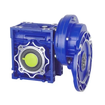
NMRV 571-150 worm gear box with flange and electric motor
NMRV+NMRV Double Stage Arrangement Reduction Gear Box
RV Series Worm Gearbox
worm speed reducer
nmrv worm gear motor
Detailed Photos
RV Series
Including RV / NMRV / NRV.
Main Characteristic of RV Series Worm Gearbox
RV series worm gear reducer is a new-generation product developed by CHINAMFG on the basis of perfecting WJ series products with a compromise of advanced technology both at home and abroad.
1. High-quality aluminum alloy, light in weight and non-rusting.
2. Large in output torque.
3. Smooth running and low noise,durable in dreadful conditions.
4. High radiation efficiency.
5. Good-looking appearance, durable in service life and small volume.
6. Suitable for omnibearing installation.
Main Materials of RV Series Worm Gearbox
1. Housing: die-cast aluminum alloy(frame size: 571 to 090), cast iron(frame size: 110 to 150).
2. Worm: 20Crm, carbonization quencher heat treatment makes the surface hardness of worm gears up to 56-62 HRX, retain carbonization layer's thickness between 0.3 and 0.5mm after precise grinding.
3. Worm Wheel: wearable stannum bronze alloy.
| SPEED RATIO | 7.5~100 |
| OUTPUT TORQUE | <1050NM |
| IN POWER | 0.09-11KW |
| MOUNTING TYPE | FOOT-MOUNTED FLANGE-MOUNTED |
Product Parameters
| When working, great load capacity, stable running, low noise with high efficiency. | |||||||
| Gear Box's Usage Field | |||||||
| 1 | Metallurgy | 11 | Agitator | ||||
| 2 | Mine | 12 | Rotary weeder | ||||
| 3 | Machine | 13 | Metallurgy | ||||
| 4 | Energy | 14 | Compressor | ||||
| 5 | Transmission | 15 | Petroleum industry | ||||
| 6 | Water Conserbancy | 16 | Air Compressor | ||||
| 7 | Tomacco | 17 | Crusher | ||||
| 8 | Medical | 18 | Materials | ||||
| 9 | Packing | 19 | Electronics | ||||
| 10 | Chemical industry | 20 | Textile indutry | ||||
| ... | ... | ||||||
| Power | 0.06kw | 0.09kw | 0.12kw | 0.18kw | 0.25kw | 0.37kw | 0.55kw |
| 0.75kw | 1.1kw | 1.5kw | 2.2kw | 3kw | 4kw | 5.5kw | |
| 7.5kw | 11kw | 15kw | |||||
| Torque | 2.6N.m-3000N.m | ||||||
| Ratio | 7.5-100, the double gearbox is more | ||||||
| Color | Blue, Silver or as customers' need | ||||||
| Material | Iron or Aluminium | ||||||
| Packing | Carton with Plywood Case or as clients' requirement | ||||||
| Type | RV571 | RV030 | RV040 | RV050 | RV063 | RV075 | RV090 |
| Weight | 0.7kg | 1.3kg | 2.3kg | 3.5kg | 6.2kg | 9kg | 13kg |
| Type | RV110 | RV130 | RV150 | ||||
| Weight | 35kg | 60kg | 84kg | ||||
Certifications
Packaging & Shipping
Company Profile
Our Advantages
FAQ
| Application: | Motor, Machinery |
|---|---|
| Hardness: | Hardened Tooth Surface |
| Installation: | Horizontal Type |
| Layout: | Worm |
| Gear Shape: | Worm |
| Step: | Single-Step |
| Customization: |
Available
| Customized Request |
|---|
Self-Locking Properties in a Worm Gearbox
Yes, worm gearboxes exhibit self-locking properties, which can be advantageous in certain applications. Self-locking refers to the ability of a mechanism to prevent the transmission of motion from the output shaft back to the input shaft when the system is at rest. Worm gearboxes inherently possess self-locking properties due to the unique design of the worm gear and worm wheel.
The self-locking behavior arises from the angle of the helix on the worm shaft. In a properly designed worm gearbox, the helix angle of the worm is such that it creates a mechanical advantage that resists reverse motion. When the gearbox is not actively driven, the friction between the worm threads and the worm wheel teeth creates a locking effect.
This self-locking feature makes worm gearboxes particularly useful in applications where holding a load in position without external power is necessary. For instance, they are commonly used in situations where there's a need to prevent a mechanism from backdriving, such as in conveyor systems, hoists, and jacks.
However, it's important to note that while self-locking properties can be beneficial, they also introduce some challenges. The high friction between the worm gear and worm wheel during self-locking can lead to higher wear and heat generation. Additionally, the self-locking effect can reduce the efficiency of the gearbox when it's actively transmitting motion.
When considering the use of a worm gearbox for a specific application, it's crucial to carefully analyze the balance between self-locking capabilities and other performance factors to ensure optimal operation.
How to Calculate the Input and Output Speeds of a Worm Gearbox?
Calculating the input and output speeds of a worm gearbox involves understanding the gear ratio and the principles of gear reduction. Here's how you can calculate these speeds:
- Input Speed: The input speed (N1) is the speed of the driving gear, which is the worm gear in this case. It is usually provided by the manufacturer or can be measured directly.
- Output Speed: The output speed (N2) is the speed of the driven gear, which is the worm wheel. To calculate the output speed, use the formula:
N2 = N1 / (Z1 * i)
Where:
N2 = Output speed (rpm)
N1 = Input speed (rpm)
Z1 = Number of teeth on the worm gear
i = Gear ratio (ratio of the number of teeth on the worm gear to the number of threads on the worm)
It's important to note that worm gearboxes are designed for gear reduction, which means that the output speed is lower than the input speed. Additionally, the efficiency of the gearbox, friction, and other factors can affect the actual output speed. Calculating the input and output speeds is crucial for understanding the performance and capabilities of the worm gearbox in a specific application.

Advantages of Using a Worm Reducer in Mechanical Systems
Worm reducers offer several advantages that make them suitable for various mechanical systems:
- High Gear Reduction Ratio: Worm gearboxes provide significant speed reduction, making them ideal for applications that require a high gear reduction ratio without the need for multiple gears.
- Compact Design: Worm reducers have a compact and space-saving design, allowing them to be used in applications with limited space.
- Self-Locking: Worm gearboxes exhibit self-locking properties, which means that the worm screw can prevent the worm wheel from reversing its motion. This is beneficial for applications where the gearbox needs to hold a load in place without external braking mechanisms.
- Smooth and Quiet Operation: Worm gearboxes operate with a sliding motion between the teeth, resulting in smoother and quieter operation compared to some other types of gearboxes.
- High Torque Transmission: Worm gearboxes can transmit high torque levels, making them suitable for applications that require powerful torque output.
- Heat Dissipation: The sliding action between the worm screw and the worm wheel contributes to heat dissipation, which can be advantageous in applications that generate heat during operation.
- Stable Performance: Worm reducers offer stable and reliable performance, making them suitable for continuous operation in various industrial and mechanical systems.
Despite these advantages, it's important to note that worm gearboxes also have limitations, such as lower efficiency compared to other gear types due to the sliding motion and potential for higher heat generation. Therefore, selecting the appropriate type of gearbox depends on the specific requirements and constraints of the application.
editor by CX 2023-09-15