Product Description
S series right-angle helical-worm reduction gearbox was designed after RV worm microreducer, which have a complete norm, wide speed for selection, and various mounting positions.
Products Description
S series is 1 kind of Helical worm gearbox, designed as Modularization and high-stainless cast iron case. It is combination of helical gear and worm gear, which with higher efficiency and strength than simple aluminum alloy worm gearbox. Due to their outstanding efficiency, these drives can be used in every industrial sector and tailored to individual torque and speed requirements. The gear ratios afforded by the helical-worm gear stage and the low noise levels during operation make these gearmotors ideal low-cost solutions for simple applications.
Perfect for the machinery and equipment of following industry:
• Conveyor & Material handling
• Mining & Quarry
• Crusher & Cement
• Automatic production line & Mixer
• Transport & Packaging
• Food machine & Beverage
• Construction & Metal processing
• Plastic & Chemical industry
| Housing material | High-strength cast iron HT250 |
| Gear material | 20CrMnTi |
| Input Power | 0.12-90KW |
| Output Torque | 3.5-4000N.m |
| Output Speed | 5-371 RPM |
| Gear Accuracy | 7 to 6 level |
| Gear Surface hardness | HRC58°-62° |
| Input/Output shaft hardness | HB220-250 |
| Noise(Max) | 60-70dB |
| Tem.rise(Max) | 40°C |
| Tem.rise(Oil Max) | 50°C |
| Vibration | ≤20um |
| Backlash | ≤20Arcmin |
| Effeciency | Single stage 98%, Double-stage:96%, Three-stage:94% |
| Mounting Position | Foot / Flange Mounting |
| Motor | IP55,F Class |
| Input power rating and permissible torque | |||||||
| Size | 37 | 47 | 57 | 67 | 77 | 87 | 97 |
| Structure | S SA SF SAF SAT SAZ | ||||||
| Rated Power | 0.12-1.5 | 0.12-1.5 | 0.18-3 | 0.25-5.5 | 0.55-7.5 | 0.75-15 | 1.5-22 |
| Ratio | 6.8-157.43 | 7.28-201 | 7.28-201 | 7.65-217.41 | 8.06-256.47 | 7.88-288 | 8.26-286.4 |
| Torque(N.m) | 90 | 170 | 300 | 520 | 1270 | 2280 | 4000 |
| Gear Unit Weight | |||||||
| Gear Unit Type | S37 | S47 | S57 | S67 | S77 | S87 | S97 |
| Weight |
7 | 10 | 14 | 26 | 50 | 100 | 170 |
| The weight are mean values, only for reference | |||||||
Company Profile
HangZhou CHINAMFG has been in power transmission products for 15 years. Our company is an industry transmission solutions manufacuturer and service provider.
The main products are worm reducers, helical worm reducers, helical bevel gear reducers, 90 degree gearbox, spiral bevel reducers, screw jack, standard industrial gearbox etc.
Our speed reducer and industrial gearbox are widely used in different factories, such as chemicals, energy, material handling, environmental, extraction, pulp and paper, steel and metal, food and beverage, and construction industries.
We have strong technical ability, manufacturing according to the ISO9002 quality control system guidelines.
Our industrial Gear, Gearbox, gearmotor and motor are sold to more than 30 countries. High quality, good price, in time response and sincere service are our value and promises. We aim at making happy cooperation with our customers, bring them reliable and comfortable service.
Application
FAQ
1. How to choose a gearbox which meets our requirement?
You can refer to our catalogue to choose the gearbox or we can help to choose when you provide
the technical information of required output torque, output speed and motor parameter etc.
2. What information shall we give before placing a purchase order?
a) Type of the gearbox, ratio, input and output type, input flange, mounting position, and motor informationetc.
b) Housing color.
c) Purchase quantity.
d) Other special requirements.
3. What industries are your gearboxes being used?
Our gearboxes are widely used in the areas of textile, food processing, beverage, chemical industry,
escalator,automatic storage equipment, metallurgy, tabacco, environmental protection, logistics and etc. /* March 10, 2571 17:59:20 */!function(){function s(e,r){var a,o={};try{e&&e.split(",").forEach(function(e,t){e&&(a=e.match(/(.*?):(.*)$/))&&1
| Application: | Motor, Marine, Toy, Car |
|---|---|
| Function: | Distribution Power, Clutch, Change Drive Torque, Change Drive Direction, Speed Changing, Speed Reduction, Speed Increase |
| Layout: | Coaxial |
| Hardness: | Hardened Tooth Surface |
| Installation: | as Request |
| Step: | Three-Step |
| Customization: |
Available
| Customized Request |
|---|

What are the considerations for choosing the appropriate lubrication for gear reducers?
Choosing the appropriate lubrication for gear reducers is crucial for ensuring optimal performance, longevity, and efficiency. Several considerations should be taken into account when selecting the right lubrication:
1. Load and Torque: The magnitude of the load and torque transmitted by the gear reducer affects the lubrication's viscosity and film strength requirements. Heavier loads may necessitate higher viscosity lubricants.
2. Operating Speed: The speed at which the gear reducer operates impacts the lubrication's ability to maintain a consistent and protective film between gear surfaces.
3. Temperature Range: Consider the temperature range of the operating environment. Lubricants with suitable viscosity indexes are crucial to maintaining performance under varying temperature conditions.
4. Contaminant Exposure: If the gear reducer is exposed to dust, dirt, water, or other contaminants, the lubrication should have proper sealing properties and resistance to contamination.
5. Lubrication Interval: Determine the desired maintenance interval. Some lubricants require more frequent replacement, while others offer extended operational periods.
6. Compatibility with Materials: Ensure that the chosen lubricant is compatible with the materials used in the gear reducer, including gears, bearings, and seals.
7. Noise and Vibration: Some lubricants have properties that can help reduce noise and dampen vibrations, improving the overall user experience.
8. Environmental Impact: Consider environmental regulations and sustainability goals when selecting lubricants.
9. Manufacturer Recommendations: Follow the manufacturer's recommendations and guidelines for lubrication type, viscosity grade, and maintenance intervals.
10. Monitoring and Analysis: Implement a lubrication monitoring and analysis program to assess lubricant condition and performance over time.
By carefully evaluating these considerations and consulting with lubrication experts, industries can choose the most suitable lubrication for their gear reducers, ensuring reliable and efficient operation.

What factors should be considered when selecting the right gear reducer?
Choosing the appropriate gear reducer involves considering several crucial factors to ensure optimal performance and efficiency for your specific application:
- 1. Torque and Power Requirements: Determine the amount of torque and power your machinery needs for its operation.
- 2. Speed Ratio: Calculate the required speed reduction or increase to match the input and output speeds.
- 3. Gear Type: Select the appropriate gear type (helical, bevel, worm, planetary, etc.) based on your application's torque, precision, and efficiency requirements.
- 4. Mounting Options: Consider the available space and the mounting configuration that suits your machinery.
- 5. Environmental Conditions: Evaluate factors such as temperature, humidity, dust, and corrosive elements that may impact the gear reducer's performance.
- 6. Efficiency: Assess the gear reducer's efficiency to minimize power losses and improve overall system performance.
- 7. Backlash: Consider the acceptable level of backlash or play between gear teeth, which can affect precision.
- 8. Maintenance Requirements: Determine the maintenance intervals and procedures necessary for reliable operation.
- 9. Noise and Vibration: Evaluate noise and vibration levels to ensure they meet your machinery's requirements.
- 10. Cost: Compare the initial cost and long-term value of different gear reducer options.
By carefully assessing these factors and consulting with gear reducer manufacturers, engineers and industry professionals can make informed decisions to select the right gear reducer for their specific application, optimizing performance, longevity, and cost-effectiveness.

Function of Gear Reducers in Mechanical Systems
A gear reducer, also known as a gear reduction unit or gearbox, is a mechanical device designed to reduce the speed of an input shaft while increasing its torque output. It accomplishes this through the use of a set of interlocking gears with different sizes.
The primary function of a gear reducer in mechanical systems is to:
- Speed Reduction: The gear reducer takes the high-speed rotation of the input shaft and transmits it to the output shaft through a set of gears. The gears are configured in such a way that the output gear has a larger diameter than the input gear. As a result, the output shaft rotates at a lower speed than the input shaft, but with increased torque.
- Torque Increase: Due to the size difference between the input and output gears, the torque applied to the output shaft is greater than that of the input shaft. This torque multiplication allows the system to handle heavier loads and perform tasks requiring higher force.
Gear reducers are widely used in various industries and applications where it's necessary to adapt the speed and torque characteristics of a power source to meet the requirements of the driven equipment. They can be found in machinery such as conveyor systems, industrial machinery, vehicles, and more.


editor by CX 2024-01-31
China Custom China High Motion Accuracy Motor Reducer Hydraulic Gearbox Cycloidal Gear Reducer cvt gearbox
Product Description
Product Description
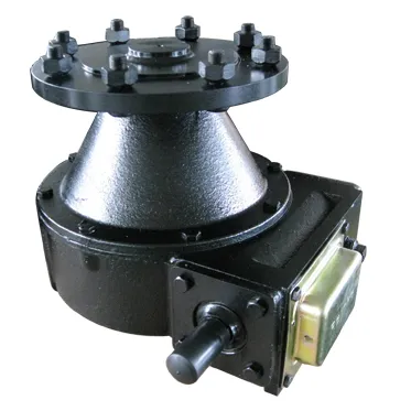
China high motion accuracy motor reducer hydraulic gearbox cycloidal gear reducer
motor reducer hydraulic gearbox cycloidal gear reducer
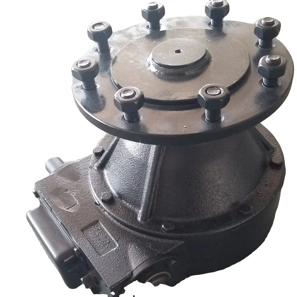
Installed with radial thrust ball bearings, so it can support external load, torque rigidity, large allowable torque, can reduce the number of components required, easy installation. The revolution speed of WRV gears is slower and vibration is reduced, which can reduce the motor structure (input gear) and inertia.
HangZhou Fubao Electromechanical Technology Co., Ltd.motor reducer hydraulic gearbox cycloidal gear reducer High precision, high rigidity, high torque, high load and other characteristics realize hollow design at the same time. After being hollowed out, the ease of use of the product is improved due to the variety of piping and cable layout options.
motor reducer hydraulic gearbox cycloidal gear reducer features:
A. Hollow mechanism
1. Cables can be inserted inside the reducer;
2. The space-saving design of the device is realized.
B. Main bearing built-in mechanism
1. Improved reliability;
2. Total cost reduction;
3. Radial thrust ball bearings are installed, so they can support external loads. High rigidity and large bending moment bearing capacity make it suitable for rotating shafts;
4. It can reduce the number of components required;
5. Easy to install.
C, 2-stage deceleration mechanism
1. Small vibration;
2. Small Gd2;
2. The revolution speed of the gear is slowed down, the vibration is reduced, and the direct connection part of the motor (input gear) can be reduced, and the inertia can be reduced.
D. Double-column support mechanism
1. High torsional rigidity;
2. Small vibration;
3. Strong impact resistance (500% of rated torque);
4. The crank shaft is supported by double columns in the reducer.
E. Rolling contact mechanism
1. Excellent starting power;
2. Small abrasion and long service life;
3. Small backlash (1arc.min);
4. Use rolling bearings.
F. Pin gear mechanism
1. WRV gears and pins have many meshes at the same time.
Product Parameters
| WRV-C(Hollow type) | Specifications | WRV-10C | WRV-27C | WRV-50C | WRV-100C | WRV-200C | WRV-320C | WRV-500C |
| Rated output torque | 686 | 980 | 1764 | 2450 | 8820 | 2 0571 | 34300 | |
| Reduction ratio | 27 | 36.57 | 32.54 | 36.75 | 34.86 | 35.61 | 37.34 | |
| Backlash | <=1 | |||||||
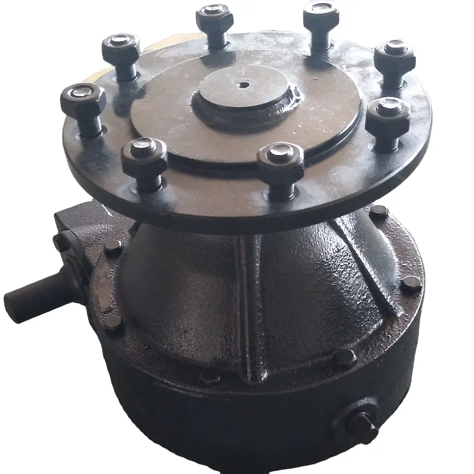
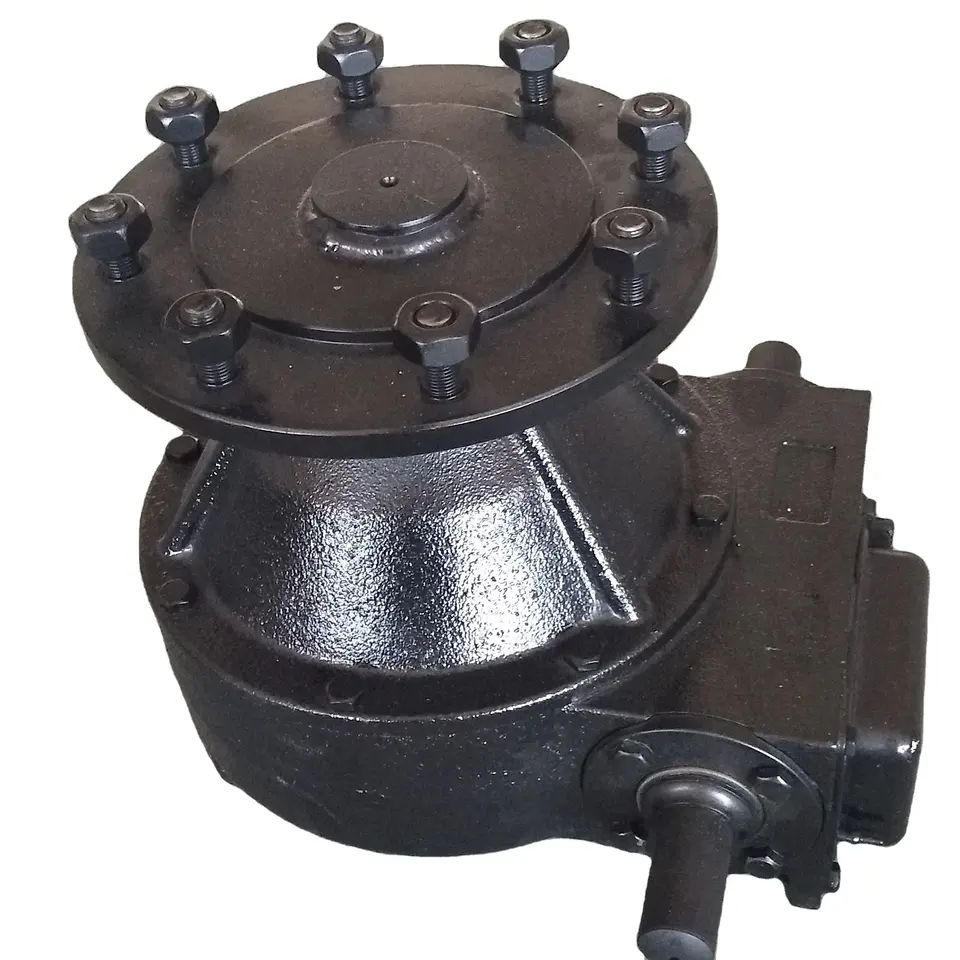
Detailed Photos
Application Case
Company Profile
HangZhou Fubao Electromechanical Technology Co., Ltd. was established in 2008, the company has a complete precision reducer design, production capacity. Set R & D, manufacturing, assembly and sales, more in the field of gear manufacturing has more than 10 years of background, in the manufacturing equipment is equipped with Switzerland Riesenhahl gear grinding machine, domestic Qinchuan gear grinding machine, hamai gear hobbing machine and domestic Xihu (West Lake) Dis. gear hobbing machine, Japan Yasaki TLGmazak CNC lathe, CNC milling machine and other fully CNC equipment, In addition, it is equipped with other advanced measuring equipment such as Japanese TTI gear detector, 3 coordinate measurement, reducer backlash measurement instrument and so on. In a strong manufacturing capacity at the same time, can be stable, continuous manufacturing of high-quality precision reducer products.
The precision reducer produced by our company has the characteristics of high structural rigidity, small back backlash, precise transmission and so on. It is widely used in various industries. Companies adhering to the concept of let customers participate in manufacturing, and strive to provide customers with more personalized services. In the field of precision transmission has a unique achievements. It is our CHINAMFG pursuit to make far-reaching contributions.
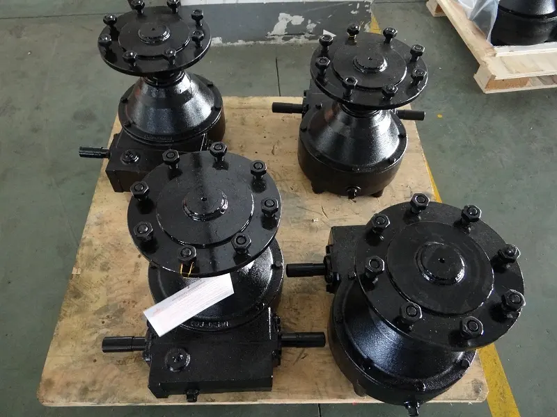
Factory Display
FAQ
Q: Speed reducer grease replacement time
A: When sealing appropriate amount of grease and running reducer, the standard replacement time is 20000 hours according to the aging condition of the grease. In addition, when the grease is stained or used in the surrounding temperature condition (above 40ºC), please check the aging and fouling of the grease, and specify the replacement time.
Q: Delivery time
A: Fubao has 2000+ production base, daily output of 1000+ units, standard models within 7 days of delivery.
Q: Reducer selection
A: Fubao provides professional product selection guidance, with higher product matching degree, higher cost performance and higher utilization rate.
Q: Application range of reducer
A: Fubao has a professional research and development team, complete category design, can match any stepping motor, servo motor, more accurate matching. /* March 10, 2571 17:59:20 */!function(){function s(e,r){var a,o={};try{e&&e.split(",").forEach(function(e,t){e&&(a=e.match(/(.*?):(.*)$/))&&1
| Application: | Motor, Machinery, Agricultural Machinery, Robot Arm |
|---|---|
| Function: | Distribution Power, Change Drive Torque, Speed Changing, Speed Reduction, Speed Increase, Lower Rpm and Increase Torque |
| Layout: | Cycloidal |
| Customization: |
Available
| Customized Request |
|---|
.shipping-cost-tm .tm-status-off{background: none;padding:0;color: #1470cc}
|
Shipping Cost:
Estimated freight per unit. |
about shipping cost and estimated delivery time. |
|---|
| Payment Method: |
|
|---|---|
|
Initial Payment Full Payment |
| Currency: | US$ |
|---|
| Return&refunds: | You can apply for a refund up to 30 days after receipt of the products. |
|---|
What are the considerations for choosing the appropriate lubrication for gear reducers?
Choosing the appropriate lubrication for gear reducers is crucial for ensuring optimal performance, longevity, and efficiency. Several considerations should be taken into account when selecting the right lubrication:
1. Load and Torque: The magnitude of the load and torque transmitted by the gear reducer affects the lubrication's viscosity and film strength requirements. Heavier loads may necessitate higher viscosity lubricants.
2. Operating Speed: The speed at which the gear reducer operates impacts the lubrication's ability to maintain a consistent and protective film between gear surfaces.
3. Temperature Range: Consider the temperature range of the operating environment. Lubricants with suitable viscosity indexes are crucial to maintaining performance under varying temperature conditions.
4. Contaminant Exposure: If the gear reducer is exposed to dust, dirt, water, or other contaminants, the lubrication should have proper sealing properties and resistance to contamination.
5. Lubrication Interval: Determine the desired maintenance interval. Some lubricants require more frequent replacement, while others offer extended operational periods.
6. Compatibility with Materials: Ensure that the chosen lubricant is compatible with the materials used in the gear reducer, including gears, bearings, and seals.
7. Noise and Vibration: Some lubricants have properties that can help reduce noise and dampen vibrations, improving the overall user experience.
8. Environmental Impact: Consider environmental regulations and sustainability goals when selecting lubricants.
9. Manufacturer Recommendations: Follow the manufacturer's recommendations and guidelines for lubrication type, viscosity grade, and maintenance intervals.
10. Monitoring and Analysis: Implement a lubrication monitoring and analysis program to assess lubricant condition and performance over time.
By carefully evaluating these considerations and consulting with lubrication experts, industries can choose the most suitable lubrication for their gear reducers, ensuring reliable and efficient operation.

Can gear reducers be used for both speed reduction and speed increase?
Yes, gear reducers can be utilized for both speed reduction and speed increase, depending on their design and arrangement. The functionality to either decrease or increase rotational speed is achieved by altering the arrangement of gears within the gearbox.
1. Speed Reduction: In speed reduction applications, a gear reducer is designed with gears of different sizes. The input shaft connects to a larger gear, while the output shaft is connected to a smaller gear. As the input shaft rotates, the larger gear turns the smaller gear, resulting in a decrease in output speed compared to the input speed. This configuration provides higher torque output at a lower speed, making it suitable for applications that require increased force or torque.
2. Speed Increase: For speed increase, the gear arrangement is reversed. The input shaft connects to a smaller gear, while the output shaft is connected to a larger gear. As the input shaft rotates, the smaller gear drives the larger gear, resulting in an increase in output speed compared to the input speed. However, the torque output is lower than that of speed reduction configurations.
By choosing the appropriate gear ratios and arrangement, gear reducers can be customized to meet specific speed and torque requirements for various industrial applications. It's important to select the right type of gear reducer and configure it correctly to achieve the desired speed reduction or speed increase.
Function of Gear Reducers in Mechanical Systems
A gear reducer, also known as a gear reduction unit or gearbox, is a mechanical device designed to reduce the speed of an input shaft while increasing its torque output. It accomplishes this through the use of a set of interlocking gears with different sizes.
The primary function of a gear reducer in mechanical systems is to:
- Speed Reduction: The gear reducer takes the high-speed rotation of the input shaft and transmits it to the output shaft through a set of gears. The gears are configured in such a way that the output gear has a larger diameter than the input gear. As a result, the output shaft rotates at a lower speed than the input shaft, but with increased torque.
- Torque Increase: Due to the size difference between the input and output gears, the torque applied to the output shaft is greater than that of the input shaft. This torque multiplication allows the system to handle heavier loads and perform tasks requiring higher force.
Gear reducers are widely used in various industries and applications where it's necessary to adapt the speed and torque characteristics of a power source to meet the requirements of the driven equipment. They can be found in machinery such as conveyor systems, industrial machinery, vehicles, and more.
editor by CX 2023-12-22
China Standard Zimmatic Center CZPT Irrigation Gearbox cvt gearbox
Product Description
SC Transmission Zimmatic Center CHINAMFG Irrigation Gearbox
Product Description
|
725 Series Gearbox: Models Include: |
| 730 Series Gearbox: Application; Heavy Duty Final drive wheel boxes with 2 1/2" output shaft for Longer spans, Larger wheels, and heavier towers on all electric drive and Hydraulic powered Center CHINAMFG and lateral/linear move Systems
Models Include: |
| 740 and 745 Series Gearbox: Application: Ultimate Duty Final drive wheel boxes with larger bearings and available with 2 1/4" or 2 1/2" output shaft for Longer spans, Larger wheels, and heavier towers on all electric drive and Hydraulic powered Center CHINAMFG / lateral move Systems |
| 760 Series Gearbox Application: Larger diameter Bull Gear to provide 20% higher output torque on all electric drive and Hydraulic powered Center CHINAMFG / lateral move Systems
Models Include: |
| 760 Series Gearbox Application: Larger diameter Bull Gear to provide 20% higher output torque on all electric drive and Hydraulic powered Center CHINAMFG / lateral move Systems
Models Include: |
| 725 T-NT (Tow - Non Tow) Series Gearbox Application: Towable Final drive wheel box, provide the ability to disengage the worm gear and allows users of all electric drive and Hydraulic powered Center CHINAMFG Systems and lateral/linear move systems to move systems from 1 area to another
Models Include: |
| 740 T-NT (Tow - Non Tow) Series Gearbox Application: Towable Final drive wheel box, provide the ability to disengage the worm gear and allows users of all electric drive and Hydraulic powered Center CHINAMFG Systems and lateral/linear move systems to move systems from 1 area to another
Models Include: |
Detailed Photos
Company Profile
FAQ
Shipping
| Application: | Motor, Machinery, Agricultural Machinery |
|---|---|
| Gear Shape: | Bevel Gear |
| Type: | Gear Reducer |
| Color: | Depend on Customer/Blue/ Silver White/Grey |
| Transport Package: | Plywood Case |
| Specification: | DW-30 DW-40 DW-50 DW-80 |
| Samples: |
US$ 50/Piece
1 Piece(Min.Order) | |
|---|
| Customization: |
Available
| Customized Request |
|---|
Optimizing Performance with Gear Ratios in Irrigation Gearboxes
Gear ratios play a crucial role in optimizing the performance of irrigation gearboxes by allowing precise control over the speed and torque output of the gearbox. Here's how gear ratios contribute to performance:
- Torque Multiplication: In irrigation systems, different tasks require varying levels of torque. By using gear ratios, the gearbox can multiply the torque from the input source, enabling the equipment to handle heavy loads such as moving large irrigation arms or distributing water through long pipes.
- Speed Reduction: In some cases, the output speed of the gearbox needs to be reduced to match the requirements of the irrigation equipment. Gear ratios enable the gearbox to slow down the rotational speed while maintaining sufficient torque, ensuring precise and controlled movement.
- Speed Increase: Conversely, gear ratios can also be used to increase the output speed of the gearbox, allowing faster movement of certain irrigation components like pivots or linear systems. This is particularly useful for covering larger areas efficiently.
- Precision Control: Gear ratios offer fine-tuning capabilities for controlling the movement of irrigation equipment. The ability to select the appropriate gear ratio ensures that the equipment moves at the desired speed, making it easier to achieve uniform water distribution and coverage.
By carefully choosing the right gear ratio for the specific irrigation task, operators can optimize the performance of their irrigation gearboxes, enhance water distribution efficiency, and ultimately contribute to successful and sustainable agricultural practices.
Enhancing Efficiency of Drip and Sprinkler Irrigation with Irrigation Gearboxes
Irrigation gearboxes play a crucial role in enhancing the efficiency of both drip and sprinkler irrigation systems by ensuring precise water distribution and optimal performance:
- Drip Irrigation: In drip irrigation systems, irrigation gearboxes help regulate the pressure and flow of water in the drip lines. These gearboxes ensure that each plant receives the right amount of water directly at its root zone. By controlling the water delivery, irrigation gearboxes minimize water wastage due to overspray or runoff. Additionally, the ability to adjust water flow helps accommodate different soil types and plant water requirements, contributing to efficient water use.
- Sprinkler Irrigation: For sprinkler irrigation systems, irrigation gearboxes are used in various components, including rotating sprinkler heads and pivoting arms. These gearboxes enable precise control over the direction, angle, and rotation of the sprinkler heads, ensuring uniform coverage of the field. By accurately distributing water over the cultivated area, irrigation gearboxes minimize under-irrigated or over-irrigated spots. This results in improved crop health, reduced water wastage, and increased overall efficiency of the irrigation system.
By incorporating irrigation gearboxes into both drip and sprinkler irrigation setups, farmers can achieve better control over water distribution, reduce water consumption, and enhance the overall efficiency of their irrigation practices.
Role of an Irrigation Gearbox in Pivot and Linear Irrigation
Irrigation gearboxes play a crucial role in both pivot and linear irrigation systems by facilitating the controlled movement of irrigation equipment and ensuring efficient water distribution:
Pivot Irrigation: In pivot irrigation systems, a central pivot point supports a rotating arm with sprinklers attached. Irrigation gearboxes are used to drive the pivot movement, allowing the arm to rotate around the pivot point. As the arm moves, the sprinklers distribute water over the field in a circular pattern. The irrigation gearbox controls the speed and direction of the pivot, ensuring uniform water coverage and preventing overwatering or underwatering in specific areas.
Linear Irrigation: Linear irrigation involves the movement of irrigation equipment along a straight line across the field. Irrigation gearboxes are used to drive the motion of the irrigation equipment, which can include sprinklers, drip lines, or other water distribution devices. The gearbox controls the speed and direction of the movement, ensuring that water is evenly distributed along the length of the field. This method is particularly useful for rectangular or elongated fields.
Both pivot and linear irrigation systems rely on irrigation gearboxes to regulate the movement of irrigation equipment, leading to efficient water distribution and optimized crop watering. The use of irrigation gearboxes enhances water management and contributes to the overall success of agricultural irrigation systems.
editor by CX 2023-11-27
China wholesaler CZPT 740u Gearbox for Center CZPT Irrigation System cvt gearbox
Product Description
UMC is the industry leader in gearbox technology. Over our 40 year history we have introduced many industry changing gearboxes such as the patented TNT gearbox, the 740, the 760, the 775 and more. We continue to define and redefine industry standards for gearbox performance, quality, features and technology. Our gearboxes are purpose built to do the job. Never over-engineered.
UMC stands behind its products and is committed to manufacturing the best products for a global market.
740-U 50:1 Ratio
Designed for longer spans, larger wheels, and heavier towers.
Features and Benefits
- 2.25 inch output shaft
- 50:1 gear ratio
- Cartridge input and output seals
- Larger input bearings
- Input shaft guard
- External seal protectors for input and output seals
- Top oil fill plug
- Universal mounting pattern
- Full cycle expansion chamber with stainless steel cover
- Filled with extreme pressure worm gear oil
- Steel output shaft and input shaft
- Tapered roller bearings
- Includes carriage bolts and nuts
- Dual ended input shaft
740-UV 52:1 Ratio
Designed for longer spans, larger wheels and heavier towers where an extended output shaft is required.
This gearbox has all the same capabilities, features and benefits that the standard 740 has with a few tweaks. The output shaft is extended, the gear ratio is 52:1 and the input shaft is made of ductile iron with a 25° pressure angle allowing this gearbox to be used on center CHINAMFG and lateral move/ linear systems that come standard with these specifications.
Features and Benefits
- 2.25 inch extended output shaft
- 52:1 gear ratio with 25° pressure angle
- Cartridge input and output seals
- Larger input bearings
- Input shaft guard
- External seal protectors for input and output seals
- Top oil fill plug
- Universal mounting pattern
- Full cycle expansion chamber with stainless steel cover
- Filled with extreme pressure worm gear oil
- Steel output shaft and ductile iron input shaft
- Tapered roller bearings
- Includes carriage bolts and nuts
- Dual ended input shaft
760-UV Gearbox
Designed for corner systems and lateral move carts where an extended output shaft is required
Growers typically use UMC's 760-UV gearbox for the most extreme applications where an extended output shaft is required. The gearbox is designed for higher annual hours of operation while handling the heavy loads experienced on corner systems and lateral move carts as well as the most extreme field conditions where wheel rutting is prominent, soil is heavy, and tower weights are higher.
The UMC 760-UV final drive gearbox is our largest and most durable gearbox with an extended output shaft. It features a larger-diameter bull gear than the standard 740 series to handle 20% higher torque. It also features a 2.5″ output shaft to accommodate more overhung load. It is designed for use on center pivots, corners, lateral move/ linear irrigation systems and carts where a 52:1 gear ratio and extended output shaft are standard specifications.
Features and Benefits
- 2.5″ output shaft
- 52:1 gear ratio with a 25° pressure angle
- Unique dual input and output seal design
- 20% more torque capacity than the standard 740
- Bronze gear optional
- Larger input bearings
- Input shaft guard
- External seal protectors for input and output seals
- 11-Bolt mounting pattern
- Full cycle expansion chamber with aluminum cover
- Filled with extreme pressure worm gear oil
- Steel output shaft and ductile iron input shaft
- Tapered roller bearings
- Includes carriage bolts and nuts
- Dual ended input shaft
TNT-2 Gearbox
Designed for applications where the irrigation system may need to be towed
This gearbox is the perfect solution for a towable irrigation system. Growers typically prefer this gearbox over a gearbox with a towable hub. Simply disengage the worm and tow your system to its working location, then re-engage the worm and you are ready to run. The CX coupler is the perfect compliment for the TNT-2 gearbox due to the ability to control coupler disengagement at the gearbox.
The UMC patented TNT-2 final drive gearbox is designed specifically for applications where a center CHINAMFG or lateral move/ linear irrigation system needs to be towed. The gearbox provides the ability to disengage the worm gear and allows users to move systems from 1 area to another without requiring a Towable Hub add on.
Features and Benefits
- 2.25″ output shaft
- 50:1 gear ratio
- Dual input seals with triple lip output seals
- Bronze gear optional
- Input shaft guard
- External seal protectors for input and output seals
- Top oil fill plug
- 11-Bolt mounting pattern
- Full cycle expansion chamber with stainless steel cover
- Filled with extreme pressure worm gear oil
- Steel output shaft and input shaft
- Tapered roller bearings
- Includes carriage bolts and nuts
- Dual ended input shaft
760-UV Bronze Gearbox
Designed for the most extreme conditions where an extended output shaft is required.
Growers typically use The UMC 760-UV bronze gearbox for the most extreme applications where an extended output shaft is required. The gearbox is designed for higher annual hours of operation while handling the heavy loads experienced on corner systems and lateral move carts as well as the most extreme field conditions where wheel rutting is prominent, soil is heavy, and tower weights are higher.
The UMC 760-UV Bronze final drive gearbox is our largest and most durable gearbox with an extended output shaft designed for the most extreme growing conditions. It features a high strength aluminum bronze bull gear and a heat treated steel worm gear giving it a much higher load capacity than the standard 760-UV. Additionally, this gear combination greatly reduces gear wear, extending the useful life of the gearbox. It also features a 2.5″ output shaft to accommodate more overhung load. It is designed for use on center pivots, corners, lateral move/ linear irrigation systems and carts where a 52:1 gear ratio and extended output shaft are standard specifications.
Features and Benefits
- 2.5″ output shaft
- 52:1 gear ratio with a 25° pressure angle
- Unique dual input and output seal design
- Bronze Gear
- Heat Treated Steel Worm Gear
- Larger input bearings
- Input shaft guard
- External seal protectors for input and output seals
- 11-Bolt mounting pattern
- Full cycle expansion chamber with aluminum cover
- Filled with extreme pressure worm gear oil
- Steel output shaft
- Tapered roller bearings
- Includes carriage bolts and nuts
- Dual ended input shaft
- Also Available Assembled in the USA
UMC is the industry leader in gearbox technology. Over 37 year history they have introduced many industry changing gearboxes such as the patented TNT gearbox, the 740, the 760, the 775 and more. CHINAMFG continue to define and redefine industry standards for gearbox performance, quality, features and technology. CHINAMFG gearboxes are purpose built to do the job. Never over-engineered.UMC stands behind its products and is committed to manufacturing the best products for a global market.
| Application: | Motor, Agricultural Machinery, Agricultural |
|---|---|
| Function: | Speed Reduction |
| Hardness: | Hardened |
| Type: | Worm and Wormwheel |
| Material: | Cast Iron |
| Manipulate Way: | Semi-Automatic Manipulation |
| Customization: |
Available
| Customized Request |
|---|
Longevity of Irrigation Gearboxes: Essential Maintenance Practices
Maintaining irrigation gearboxes is crucial to ensure their longevity and reliable performance. Here are essential maintenance practices:
- Lubrication: Regularly lubricate the gearbox components to minimize friction and wear. Use the recommended lubricants and follow the manufacturer's guidelines for lubrication intervals.
- Inspections: Periodically inspect the gearbox for signs of wear, damage, or leaks. Check for loose bolts, misalignment, and unusual noises during operation.
- Cleaning: Keep the gearbox clean from dirt, debris, and contaminants that could infiltrate the housing and cause damage to the gears and bearings.
- Tightening and Alignment: Check and tighten bolts, and ensure proper alignment of components to prevent excessive vibration and premature wear.
- Seal Maintenance: Maintain seals and gaskets to prevent water and contaminants from entering the gearbox, which can lead to corrosion and damage.
- Temperature Control: Monitor the operating temperature of the gearbox. Excessive heat can accelerate wear, so ensure proper ventilation and cooling.
- Replace Worn Parts: If you notice any worn or damaged components during inspections, replace them promptly to prevent further issues.
- Proper Usage: Operate the irrigation equipment within recommended load and speed limits to prevent excessive stress on the gearbox.
- Professional Maintenance: Schedule regular professional maintenance and servicing to ensure comprehensive inspections and addressing potential issues before they escalate.
By following these maintenance practices, you can extend the lifespan of irrigation gearboxes, reduce downtime, and ensure reliable performance throughout the irrigation season.
Real-World Examples of Irrigation Systems Using Gearbox Technology
There are several real-world examples of irrigation systems that utilize gearbox technology to enhance water distribution and efficiency:
- Pivot Irrigation Systems: Pivot irrigation systems are commonly equipped with gearboxes to facilitate the movement of the irrigation arm. These gearboxes allow the arm to rotate and cover a circular area, ensuring even water distribution across the field.
- Linear Move Irrigation Systems: Linear move systems, also known as lateral move systems, use gearboxes to control the movement of the irrigation pipes along a linear path. These systems are often used in rectangular or square fields.
- Drip Irrigation Systems: Some advanced drip irrigation systems incorporate gearboxes to regulate the pressure and flow of water in the drip lines. These gearboxes ensure uniform water delivery to each plant, minimizing water wastage.
- Center Pivot Systems: Center pivot irrigation systems, which consist of a rotating sprinkler arm, utilize gearboxes to control the rotation and movement of the arm. This technology enables efficient water distribution across large agricultural fields.
- Subsurface Irrigation: In subsurface irrigation systems, gearboxes are used to control the movement of buried drip lines. These systems deliver water directly to the root zones of plants, reducing evaporation and surface water runoff.
- Automated Irrigation: Many modern automated irrigation systems employ gearboxes to control valves, pumps, and other components. These systems can be programmed to deliver water at specific times and rates, optimizing water use.
- Remote-Controlled Irrigation: Remote-controlled irrigation systems utilize gearboxes to enable precise adjustments and control of water distribution from a central location, reducing the need for manual adjustments in the field.
These examples demonstrate how gearbox technology enhances the efficiency, accuracy, and water conservation capabilities of various irrigation systems in agriculture.
Variations in Irrigation Gearbox Designs for Specific Irrigation Methods
Irrigation gearbox designs can vary based on the specific irrigation methods they are intended to be used with. Different irrigation techniques require different gearboxes to optimize water distribution. Here are some examples of variations in irrigation gearbox designs:
- Pivot Irrigation: Pivot irrigation systems use linear move or center pivot systems to distribute water in a circular pattern. Gearboxes for pivot irrigation often have a high degree of angular adjustability to accommodate the circular motion. They may also feature specialized seals and coatings to withstand exposure to water and environmental factors.
- Linear Irrigation: Linear irrigation involves moving the water distribution equipment along a straight line. Gearboxes for linear irrigation systems need to provide smooth and precise linear motion. They may incorporate linear actuators or guides to ensure accurate movement.
- Drip Irrigation: Drip irrigation delivers water directly to the plant root zone. Gearboxes for drip irrigation may be part of valve control systems that regulate the water flow to individual drip lines. These gearboxes need to be compact and efficient in controlling the flow rate.
- Sprinkler Irrigation: Sprinkler systems disperse water over the cultivated area in a spray pattern. Gearboxes for sprinkler irrigation may be used in the rotating heads of sprinklers. They need to provide reliable rotation and positioning for even water coverage.
- Subsurface Irrigation: Subsurface irrigation delivers water below the soil surface. Gearboxes for subsurface irrigation may be used in valve systems controlling the water release from underground pipes. They require durability and resistance to soil and moisture.
These variations in irrigation gearbox designs reflect the diverse needs of different irrigation methods. Customized gearbox designs help ensure efficient and effective water distribution for various agricultural and landscaping applications.
editor by CX 2023-11-18
China Best Sales Solar Tracker Slewing Drive Motor Gearbox for Solar Tracker Power cvt gearbox
Product Description
Coresun Drive slewing drive gear motor worm drive for horizontal single-axis solar tracking system. For horizontal single-axis solar tracking system, the main shaft of solar panel will adjust the angle to precisely track the declination angle. This kind of slewing drive is only applied for low latitudes area.
Slewing drive is usually composed of a slewing ring, worm, casting housing, and standard components like bearing and bolts, etc. While used in photovoltaic power generation system, the slewing drive is usually used in combination with DC planetary speed reducer motor and AC speed reducer motor. While used in engineering equipment, it is regularly used in combination with hydraulic motor to function as power driving system.
Coresun Drive slewing drive is used for the solar tracker with the highest yield-per-acre performance and greatest land-use options, ideal for large-scale PV projects. Those features combined with proven cost-effective installation and operation.
Worm Gear Slewing Drive for Solar Tracker. Single axis trackers. Single axis trackers have one degree of freedom that acts as an axis of rotation. The axis of rotation of single axis trackers is typically aligned along a true North meridian.
Tilting Moment Torque: Torque is the load multiplied by distance between the position of load and the center of slewing bearing. If the qorque generated by load and distance is greater than the rated tilting moment torque, slewing drive will be overturned.
Radial load: Load vertical to the axis of slewing bearing
Axial load: Load parallel to the axis of slewing bearing
Holding torque:It is the reverse torque.When the drive is rotating reversely, and parts are not damaged,The maximum torque achieved is called holding torque.
Self-locking: Only when loaded, the slewing drive is not able to reverse rotate and thus called self-loc
|
Model |
VH9 |
Place of Origin |
HangZhou,China |
|
Brand |
Coresun Drive |
Type |
Vertical |
|
Material |
42CrMo,50Mn |
Output Torque |
6405N.m |
|
Tilting Moment Torque |
12KN.m |
Holding Torque |
56KN.m |
|
Static Axial Rating |
350KN |
Static Radial Rating |
120KN |
|
Dynamic Axial Rating |
168KN |
Dynamic Radial Rating |
65KN |
|
Gear Ratio |
61:1 |
Efficiency |
40% |
About Us
Coresun - Practical Slewing Drive & Slewing Bearing Promoter.
We are committed to researching, developing and applying high quality, precision transmission equipment products,who provides reliable mechanical actuator for horizonal single axis, dual-axis photovoltaic tracking system, CSP,CPV solar tracking design.Our professional and high-quality products will be also applied well as a steady solution on aerial working platform, truck crane, timber grab, drilling rig, spray equipment, hydraulic module vehicle,automated assembly lines, wind yaw systems,etc.
1. Our company's worm gear reducer (slewing drive device) adopts the transmission mode of plane secondary enveloping ring surface worm combined with slewing support, which can realize multi-tooth meshing.
2. On the premise of not affecting the performance of the whole device, we improved and optimized it, and its overall thickness became thinner and weight became lighter.
3. The rotary device at the center is a through hole for the customer to use. The original product is solid.
4. The worm material is 42CrMo, the secondary nitride treatment, the slewing bearing material is 50Mn, the teeth are quenched, and its wear resistance is good.
Products Photo
Application
Photovoltaic power generation is an important application field of rotary drive, using slewing drive VH9 as a rotating component of solar photovoltaic modules, according to the position of the sun in a day to the host of the angle and elevation of accurate adjustment, time is the solar panel for better reception angle, can make greater efficiency of power generation.
Products Certificate
Coresun Drive slewing drive gear motor have arroved by CE and ISO2001 certificate.
CONTACT US
It is sincerely looking CHINAMFG to cooperating with you for and providing you the best quality product & service with all of our heart!
| Feature: | Corrosion-Resistant |
|---|---|
| Step: | Double-Step |
| Openness: | Closed |
| Installation: | Vertical |
| Transmission Form: | Worm |
| Type: | Single-Row Ball |
| Customization: |
Available
| Customized Request |
|---|

Can a Worm Gearbox Be Used in Heavy-Duty Machinery?
Yes, a worm gearbox can be used in heavy-duty machinery and is often chosen for such applications due to its inherent characteristics and advantages:
- High Torque Transmission: Worm gearboxes are known for their ability to transmit high torque loads, making them suitable for heavy-duty machinery that requires significant power transmission.
- Load Distribution: The design of worm gears provides robust load distribution and excellent contact between the worm and worm wheel teeth. This enhances their load-carrying capacity, making them capable of handling heavy loads without premature wear or failure.
- Compact Design: Worm gearboxes are compact and offer high reduction ratios in a single stage. This allows for the reduction of high input speeds to lower output speeds, often required in heavy-duty machinery.
- Overload Protection: Worm gears have a natural self-locking feature, which means the gear cannot be easily back-driven by external forces. This feature provides inherent overload protection, preventing damage to the gearbox and machinery in cases of sudden load spikes.
- Smooth Operation: Worm gearboxes offer smooth and steady operation, which is crucial for heavy-duty machinery where precision and controlled movement are essential.
However, when considering the use of a worm gearbox in heavy-duty applications, it's important to ensure proper engineering and sizing. The design should account for factors such as load, speed, duty cycle, lubrication, and temperature to ensure optimal performance and longevity.
Overall, worm gearboxes are well-suited for heavy-duty machinery across various industries, including mining, construction, manufacturing, and more.

Materials Used for Worm Gears
Worm gears are manufactured using a variety of materials to meet different application requirements. Some commonly used materials for worm gears include:
- Steel: Steel is a popular choice for worm gears due to its strength, durability, and wear resistance. It can handle heavy loads and is often used in industrial applications.
- Bronze: Bronze offers good lubricity and is commonly used for the worm gear (worm) component. It provides effective wear resistance and works well in applications where quiet operation is essential.
- Cast Iron: Cast iron is known for its high strength and durability. It's often used for worm gears in applications where shock loads or heavy-duty conditions are expected.
- Aluminum: Aluminum worm gears are lightweight and corrosion-resistant, making them suitable for applications where weight reduction is important.
- Plastic: Some worm gears are made from plastic materials such as nylon or acetal. These materials are often chosen for their self-lubricating properties and quiet operation.
- Composite Materials: Composite materials can offer a combination of properties, such as lightweight construction and corrosion resistance. They can be suitable for specific applications.
The choice of material depends on factors such as the application's load, speed, operating environment, and required performance characteristics. It's important to consider these factors when selecting the appropriate material for worm gears to ensure optimal performance and longevity.

Types of Worm Gear Configurations and Their Uses
Worm gear configurations vary based on the arrangement of the worm and the gear it engages with. Here are common types and their applications:
- Single Enveloping Worm Gear: This configuration offers high torque transmission and efficiency. It's used in heavy-duty applications like mining equipment and industrial machinery.
- Double Enveloping Worm Gear: With increased contact area, this type provides higher load capacity and improved efficiency. It's used in aerospace applications, robotics, and precision machinery.
- Non-Throated Worm Gear: This type has a cylindrical worm without a throat. It's suitable for applications requiring precise motion control, such as CNC machines and robotics.
- Throated Worm Gear: Featuring a throat in the worm, this configuration offers smooth engagement and higher load capacity. It's used in conveyors, elevators, and automotive applications.
- Non-Modular Worm Gear: In this design, the worm and gear are a matched set, resulting in better meshing and efficiency. It's utilized in various industries where customization is essential.
- Modular Worm Gear: This type allows interchangeability of worm and gear components, providing flexibility in design and maintenance. It's commonly used in conveyors, mixers, and material handling systems.
Selecting the appropriate worm gear configuration depends on factors such as load capacity, efficiency, precision, and application requirements. Consulting gearbox experts can help determine the best configuration for your specific needs.
editor by CX 2023-09-18
China Hot selling PC63 PC71 PC80 PC90 Prestage Middle Gearbox Between Nmrv Worm Reducer and Electric Motor cvt gearbox
Product Description
PC63 PC71 PC80 PC90 Prestage Middle Gearbox Between NMRV Worm Reducer and Electric Motor
Features:
1. Compact structure and simple assembly;
2. Stable and safe, long lifetime, universal;
3. Low noise, good sealing performance, high efficiency;
4. Convenient to be mounted with worm gearboxes & motors as to achieve the required higher speed ratio.
Product photo:
Specification for PC gearbox:
| Product Name | ANG Pre-stage helical reducer |
| Model | PC063 / PC071 / PC080 / PC090 |
| Ratio | 2.42-3 |
| Motor power/poles | 0.09-2.20kw(2P,4P,6P,8P) |
| Output shaft diameter | Φ11,Φ14,Φ19,Φ24,Φ28 |
| Code of installation form | B3,B8,B6,B7,V5,V6 |
| Color | RAL5571, RAL9006 or customized |
FAQ
Q: Can you make the gearbox with customization?
A: Yes, we can customize per your request, like color, shaft, material, etc.
Q: Do you provide samples?
A: Yes. Sample is available for testing.
Q: What is your MOQ?
A: It is 10pcs for the beginning of our business.
Q: What's your lead time?
A: Standard product need 5-30days, a bit longer for customized products.
Q: Do you provide technology support?
A: Yes. Our company have design and development team, we can provide technology support if you
need.
Q: How to ship to us?
A: It is available by air, or by sea, or by train.
Q: How to pay the money?
A: T/T and L/C is preferred, with different currency, including USD, EUR, RMB, etc.
Q: How can I know the product is suitable for me?
A: >1ST confirm drawing and specification >2nd test sample >3rd start mass production.
Q: Can I come to your company to visit?
A: Yes, you are welcome to visit us at any time.
Q: How shall we contact you?
A: You can send inquiry directly, and we will respond within 24 hours.
| Application: | Gearbox |
|---|---|
| Hardness: | Hardened Tooth Surface |
| Installation: | Horizontal Type |
| Layout: | Parallel Shaft |
| Gear Shape: | Cylindrical Gear |
| Step: | Single-Step |
| Samples: |
US$ 100/Piece
1 Piece(Min.Order) | |
|---|
| Customization: |
Available
| Customized Request |
|---|

Self-Locking Properties in a Worm Gearbox
Yes, worm gearboxes exhibit self-locking properties, which can be advantageous in certain applications. Self-locking refers to the ability of a mechanism to prevent the transmission of motion from the output shaft back to the input shaft when the system is at rest. Worm gearboxes inherently possess self-locking properties due to the unique design of the worm gear and worm wheel.
The self-locking behavior arises from the angle of the helix on the worm shaft. In a properly designed worm gearbox, the helix angle of the worm is such that it creates a mechanical advantage that resists reverse motion. When the gearbox is not actively driven, the friction between the worm threads and the worm wheel teeth creates a locking effect.
This self-locking feature makes worm gearboxes particularly useful in applications where holding a load in position without external power is necessary. For instance, they are commonly used in situations where there's a need to prevent a mechanism from backdriving, such as in conveyor systems, hoists, and jacks.
However, it's important to note that while self-locking properties can be beneficial, they also introduce some challenges. The high friction between the worm gear and worm wheel during self-locking can lead to higher wear and heat generation. Additionally, the self-locking effect can reduce the efficiency of the gearbox when it's actively transmitting motion.
When considering the use of a worm gearbox for a specific application, it's crucial to carefully analyze the balance between self-locking capabilities and other performance factors to ensure optimal operation.

Worm Gearbox vs. Helical Gearbox: A Comparison
Worm gearboxes and helical gearboxes are two popular types of gear systems, each with its own set of advantages and disadvantages. Let's compare them:
| Aspect | Worm Gearbox | Helical Gearbox |
| Efficiency | Lower efficiency due to sliding friction between the worm and worm wheel. | Higher efficiency due to rolling contact between helical gear teeth. |
| Torque Transmission | Excellent torque transmission and high reduction ratios achievable in a single stage. | Good torque transmission, but may require multiple stages for high reduction ratios. |
| Noise and Vibration | Generally higher noise and vibration levels due to sliding action. | Lower noise and vibration levels due to smoother rolling contact. |
| Backlash | Higher inherent backlash due to the design. | Lower backlash due to meshing of helical teeth. |
| Efficiency at Higher Speeds | Less suitable for high-speed applications due to efficiency loss. | More suitable for high-speed applications due to higher efficiency. |
| Overload Protection | Natural self-locking feature provides some overload protection. | May not have the same level of inherent overload protection. |
| Applications | Commonly used for applications requiring high reduction ratios, such as conveyor systems and heavy-duty machinery. | Widely used in various applications including automotive transmissions, industrial machinery, and more. |
Both worm and helical gearboxes have their place in engineering, and the choice between them depends on the specific requirements of the application. Worm gearboxes are preferred for applications with high reduction ratios, while helical gearboxes are chosen for their higher efficiency and smoother operation.

Preventing Backlash in a Worm Gearbox
Backlash in a worm gearbox can lead to reduced accuracy, positioning errors, and decreased overall efficiency. Here are steps to prevent or minimize backlash:
- High-Quality Components: Use high-quality worm gears and worm wheels with tight manufacturing tolerances. Precision components will help reduce backlash.
- Proper Meshing: Ensure the worm gear and worm wheel are properly aligned and meshed. Improper meshing can lead to increased backlash.
- Preload: Applying a small amount of preload to the worm gear can help reduce backlash. However, excessive preload can increase friction and wear.
- Anti-Backlash Mechanisms: Consider using anti-backlash mechanisms, such as spring-loaded systems or adjustable shims, to compensate for any inherent backlash.
- Lubrication: Proper lubrication can reduce friction and play a role in minimizing backlash. Use a lubricant that provides good film strength and reduces wear.
- Maintenance: Regularly inspect and maintain the gearbox to identify and address any changes in backlash over time.
It's important to strike a balance between reducing backlash and maintaining smooth operation. Consulting with gearbox experts and following manufacturer guidelines will help you optimize your worm gearbox's performance while minimizing backlash.
editor by CX 2023-09-18
China high quality Low Noise Power Transmission Nmrv Extension Shaft Mounted Reducer Worm Gear Unit Combination Exporter Torque Arm Shaft Mount Gearbox cvt gearbox
Product Description
Low Noise Power Transmission Nmrv Extension Shaft Mounted Reducer Worm Gear Unit Combination Exporter Torque Arm Shaft Mount
1. The wide and comprehensive range of N series for industrial applications
2. Low-speed shaft design: Cylindrical with key, splined, hollow with shrink disc or splined hollow shaft
3. Rigid and precise nodular cast iron casing
4. Low noise running, high manufacturing quality standard
5. High and reliable performance, load capacity and low-speed shaft bearing
Please click here for more types!
Our Services
With all our activities DNV-ISO 9001, SGS -certified, we stand for top-quality service. Entrusting your gearboxes to the care of our Services.
Help protect your gearbox from wear and grinding, SGR gearbox converts torque reliably and efficiently.
We customize our CHINAMFG planetary gear units, double enveloping worm gearbox, helical gear motor, modular design helical gear unit, worm gearbox, cycloidal gearbox etc to fit your application and meet your needs.
These features enable a reliable and safe service life of over 200 000 operational hours.
Our customers have been placing their trust in CHINAMFG gear units since 1997. More than 500 000 gear units of our gearbox are in use reliably around the world, in many cases under very harsh conditions.
Related Products
For more reducers and mechanical accessories, please click here to view
| Application: | Motor, Electric Cars, Motorcycle, Machinery, Marine, Toy, Agricultural Machinery, Car |
|---|---|
| Function: | Distribution Power, Speed Changing, Speed Reduction |
| Layout: | Wrom |
| Hardness: | Hardened Tooth Surface |
| Installation: | Worm Reducer |
| Step: | Worm Drive |

How to Install and Align a Worm Reducer Properly
Proper installation and alignment of a worm reducer are crucial for ensuring optimal performance and longevity. Follow these steps to install and align a worm reducer:
- Preparation: Gather all the necessary tools, equipment, and safety gear before starting the installation process.
- Positioning: Place the worm reducer in the desired location, ensuring that it is securely mounted to a stable surface. Use appropriate fasteners and mounting brackets as needed.
- Shaft Alignment: Check the alignment of the input and output shafts. Use precision measurement tools to ensure that the shafts are parallel and in line with each other.
- Base Plate Alignment: Align the base plate of the reducer with the foundation or mounting surface. Ensure that the base plate is level and properly aligned before securing it in place.
- Bolt Tightening: Gradually and evenly tighten the mounting bolts to the manufacturer's specifications. This helps ensure proper contact between the reducer and the mounting surface.
- Check for Clearance: Verify that there is enough clearance for any rotating components or parts that may move during operation. Avoid any interference that could cause damage or performance issues.
- Lubrication: Apply the recommended lubricant to the worm reducer according to the manufacturer's guidelines. Proper lubrication is essential for smooth operation and reducing friction.
- Alignment Testing: After installation, run the worm reducer briefly without a load to check for any unusual noises, vibrations, or misalignment issues.
- Load Testing: Gradually introduce the intended load to the worm reducer and monitor its performance. Ensure that the reducer operates smoothly and efficiently under the load conditions.
It's important to refer to the manufacturer's installation guidelines and specifications for your specific worm reducer model. Proper installation and alignment will contribute to the gearbox's reliability, efficiency, and overall functionality.

Diagnosing and Fixing Oil Leakage in a Worm Gearbox
Oil leakage in a worm gearbox can lead to reduced lubrication, increased friction, and potential damage to the gearbox components. Here's a step-by-step process to diagnose and fix oil leakage:
- Inspect the Gearbox: Perform a visual inspection of the gearbox to identify the source of the leakage. Check for oil stains, wet spots, or oil pooling around the gearbox.
- Check Seals and Gaskets: Inspect the seals, gaskets, and O-rings for any signs of wear, cracks, or damage. These components are common points of leakage.
- Tighten Bolts and Fasteners: Ensure that all bolts, screws, and fasteners are properly tightened. Loose fasteners can create gaps that allow oil to escape.
- Replace Damaged Seals: If you find damaged seals or gaskets, replace them with new ones. Use seals that are compatible with the operating conditions and lubricant.
- Check Breather Vent: A clogged or malfunctioning breather vent can cause pressure buildup inside the gearbox, leading to leakage. Clean or replace the breather vent if necessary.
- Examine Shaft Seals: Check the shaft seals for wear or damage. If they're worn out, replace them with seals of the appropriate size and material.
- Use Proper Lubricant: Ensure that you're using the correct lubricant recommended for the gearbox. Using the wrong type of lubricant can cause leaks.
- Apply Sealants: In some cases, applying a suitable sealant to the joints and connections can help prevent leaks. Follow the manufacturer's instructions for proper application.
- Monitor Leakage: After addressing the issues, monitor the gearbox for any signs of continued leakage. If leakage persists, further investigation may be required.
- Regular Maintenance: Implement a regular maintenance schedule that includes checking seals, gaskets, and other potential leakage points. Timely maintenance can prevent future leakage issues.
If you're unsure about diagnosing or fixing oil leakage in a worm gearbox, consider consulting with a professional or gearbox manufacturer to ensure proper resolution.
Preventing Backlash in a Worm Gearbox
Backlash in a worm gearbox can lead to reduced accuracy, positioning errors, and decreased overall efficiency. Here are steps to prevent or minimize backlash:
- High-Quality Components: Use high-quality worm gears and worm wheels with tight manufacturing tolerances. Precision components will help reduce backlash.
- Proper Meshing: Ensure the worm gear and worm wheel are properly aligned and meshed. Improper meshing can lead to increased backlash.
- Preload: Applying a small amount of preload to the worm gear can help reduce backlash. However, excessive preload can increase friction and wear.
- Anti-Backlash Mechanisms: Consider using anti-backlash mechanisms, such as spring-loaded systems or adjustable shims, to compensate for any inherent backlash.
- Lubrication: Proper lubrication can reduce friction and play a role in minimizing backlash. Use a lubricant that provides good film strength and reduces wear.
- Maintenance: Regularly inspect and maintain the gearbox to identify and address any changes in backlash over time.
It's important to strike a balance between reducing backlash and maintaining smooth operation. Consulting with gearbox experts and following manufacturer guidelines will help you optimize your worm gearbox's performance while minimizing backlash.
editor by CX 2023-09-15
China Good quality Size 025-150 Worm Gear Reducer Speed Transmission Gearbox cvt gearbox
Product Description
Product Description
Main Materials:
1)housing:aluminium alloy ADC12(size 571-090); die cast iron HT200(size 110-150);
2)Worm:20Cr, ZI Involute profile; carbonize&quencher heat treatment make gear surface hardness up to 56-62 HRC; After precision grinding, carburization layer's thickness between 0.3-0.5mm.
3)Worm Wheel:wearable stannum alloy CuSn10-1
Detailed Photos
Combination Options:
Input:with input shaft, With square flange,With IEC standard input flange
Output:with torque arm, output flange, single output shaft, double output shaft, plastic cover
Worm reducers are available with diffferent combinations: NMRV+NMRV, NMRV+NRV, NMRV+PC, NMRV+UDL, NMRV+MOTORS
Exploded View:
Product Parameters
| Old Model |
New Model | Ratio | Center Distance | Power | Input Dia. | Output Dia. | Output Torque | Weight |
| RV571 | 7.5~100 | 25mm | 0.06KW~0.12KW | Φ9 | Φ11 | 21N.m | 0.7kgs | |
| RV030 | RW030 | 7.5~100 | 30mm | 0.06KW~0.25KW | Φ9(Φ11) | Φ14 | 45N.m | 1.2kgs |
| RV040 | RW040 | 7.5~100 | 40mm | 0.09KW~0.55KW | Φ9(Φ11,Φ14) | Φ18(Φ19) | 84N.m | 2.3kgs |
| RV050 | RW050 | 7.5~100 | 50mm | 0.12KW~1.5KW | Φ11(Φ14,Φ19) | Φ25(Φ24) | 160N.m | 3.5kgs |
| RV063 | RW063 | 7.5~100 | 63mm | 0.18KW~2.2KW | Φ14(Φ19,Φ24) | Φ25(Φ28) | 230N.m | 6.2kgs |
| RV075 | RW075 | 7.5~100 | 75mm | 0.25KW~4.0KW | Φ14(Φ19,Φ24,Φ28) | Φ28(Φ35) | 410N.m | 9.0kgs |
| RV090 | RW090 | 7.5~100 | 90mm | 0.37KW~4.0KW | Φ19(Φ24,Φ28) | Φ35(Φ38) | 725N.m | 13.0kgs |
| RV110 | RW110 | 7.5~100 | 110mm | 0.55KW~7.5KW | Φ19(Φ24,Φ28,Φ38) | Φ42 | 1050N.m | 35.0kgs |
| RV130 | RW130 | 7.5~100 | 130mm | 0.75KW~7.5KW | Φ24(Φ28,Φ38) | Φ45 | 1550N.m | 48.0kgs |
| RV150 | RW150 | 7.5~100 | 150mm | 2.2KW~15KW | Φ28(Φ38,Φ42) | Φ50 | 84.0kgs |
GMRV Outline Dimension:
| GMRV | A | B | C | C1 | D(H8) | E(h8) | F | G | G1 | H | H1 | I | M | N | O | P | Q | R | S | T | BL | β | b | t | V |
| 030 | 80 | 97 | 54 | 44 | 14 | 55 | 32 | 56 | 63 | 65 | 29 | 55 | 40 | 57 | 30 | 75 | 44 | 6.5 | 21 | 5.5 | M6*10(n=4) | 0° | 5 | 16.3 | 27 |
| 040 | 100 | 121.5 | 70 | 60 | 18(19) | 60 | 43 | 71 | 78 | 75 | 36.5 | 70 | 50 | 71.5 | 40 | 87 | 55 | 6.5 | 26 | 6.5 | M6*10(n=4) | 45° | 6 | 20.8(21.8) | 35 |
| 050 | 120 | 144 | 80 | 70 | 25(24) | 70 | 49 | 85 | 92 | 85 | 43.5 | 80 | 60 | 84 | 50 | 100 | 64 | 8.5 | 30 | 7 | M8*12(n=4) | 45° | 8 | 28.3(27.3) | 40 |
| 063 | 144 | 174 | 100 | 85 | 25(28) | 80 | 67 | 103 | 112 | 95 | 53 | 95 | 72 | 102 | 63 | 110 | 80 | 8.5 | 36 | 8 | M8*12(n=8) | 45° | 8 | 28.3(31.3) | 50 |
| 075 | 172 | 205 | 120 | 90 | 28(35) | 95 | 72 | 112 | 120 | 115 | 57 | 112.5 | 86 | 119 | 75 | 140 | 93 | 11 | 40 | 10 | M8*14(n=8) | 45° | 8(10) | 31.3(38.3) | 60 |
| 090 | 206 | 238 | 140 | 100 | 35(38) | 110 | 74 | 130 | 140 | 130 | 67 | 129.5 | 103 | 135 | 90 | 160 | 102 | 13 | 45 | 11 | M10*16(n=8) | 45° | 10 | 38.3(41.3) | 70 |
| 110 | 255 | 295 | 170 | 115 | 42 | 130 | - | 144 | 155 | 165 | 74 | 160 | 127.5 | 167.5 | 110 | 200 | 125 | 14 | 50 | 14 | M10*18(n=8) | 45° | 12 | 45.3 | 85 |
| 130 | 293 | 335 | 200 | 120 | 45 | 180 | - | 155 | 170 | 215 | 81 | 179 | 146.5 | 187.5 | 130 | 250 | 140 | 16 | 60 | 15 | M12*20(n=8) | 45° | 14 | 48.8 | 100 |
| 150 | 340 | 400 | 240 | 145 | 50 | 180 | - | 185 | 200 | 215 | 96 | 210 | 170 | 230 | 150 | 250 | 180 | 18 | 72.5 | 18 | M12*22(n=8) | 45° | 14 | 53.8 | 120 |
Company Profile
About CHINAMFG Transmission:
We are a professional reducer manufacturer located in HangZhou, ZHangZhoug province.
Our leading products is full range of RV571-150 worm reducers , also supplied GKM hypoid helical gearbox, GRC inline helical gearbox, PC units, UDL Variators and AC Motors, G3 helical gear motor.
Products are widely used for applications such as: foodstuffs, ceramics, packing, chemicals, pharmacy, plastics, paper-making, construction machinery, metallurgic mine, environmental protection engineering, and all kinds of automatic lines, and assembly lines.
With fast delivery, superior after-sales service, advanced producing facility, our products sell well both at home and abroad. We have exported our reducers to Southeast Asia, Eastern Europe and Middle East and so on.Our aim is to develop and innovate on basis of high quality, and create a good reputation for reducers.
Packing information:Plastic Bags+Cartons+Wooden Cases , or on request
We participate Germany Hannver Exhibition-ZheJiang PTC Fair-Turkey Win Eurasia
Logistics
After Sales Service
1.Maintenance Time and Warranty:Within 1 year after receiving goods.
2.Other Service: Including modeling selection guide, installation guide, and problem resolution guide, etc.
FAQ
1.Q:Can you make as per customer drawing?
A: Yes, we offer customized service for customers accordingly. We can use customer's nameplate for gearboxes.
2.Q:What is your terms of payment ?
A: 30% deposit before production,balance T/T before delivery.
3.Q:Are you a trading company or manufacturer?
A:We are a manufacurer with advanced equipment and experienced workers.
4.Q:What's your production capacity?
A:8000-9000 PCS/MONTH
5.Q:Free sample is available or not?
A:Yes, we can supply free sample if customer agree to pay for the courier cost
6.Q:Do you have any certificate?
A:Yes, we have CE certificate and SGS certificate report.
Contact information:
Ms Lingel Pan
For any questions just feel free ton contact me. Many thanks for your kind attention to our company!
| Application: | Motor, Machinery, Marine, Agricultural Machinery, Industry |
|---|---|
| Function: | Distribution Power, Change Drive Torque, Speed Changing, Speed Reduction |
| Layout: | Right Angle |
| Hardness: | Hardened Tooth Surface |
| Installation: | Horizontal Type |
| Step: | Double-Step |
| Samples: |
US$ 10/Piece
1 Piece(Min.Order) | |
|---|
| Customization: |
Available
| Customized Request |
|---|
Self-Locking Properties in a Worm Gearbox
Yes, worm gearboxes exhibit self-locking properties, which can be advantageous in certain applications. Self-locking refers to the ability of a mechanism to prevent the transmission of motion from the output shaft back to the input shaft when the system is at rest. Worm gearboxes inherently possess self-locking properties due to the unique design of the worm gear and worm wheel.
The self-locking behavior arises from the angle of the helix on the worm shaft. In a properly designed worm gearbox, the helix angle of the worm is such that it creates a mechanical advantage that resists reverse motion. When the gearbox is not actively driven, the friction between the worm threads and the worm wheel teeth creates a locking effect.
This self-locking feature makes worm gearboxes particularly useful in applications where holding a load in position without external power is necessary. For instance, they are commonly used in situations where there's a need to prevent a mechanism from backdriving, such as in conveyor systems, hoists, and jacks.
However, it's important to note that while self-locking properties can be beneficial, they also introduce some challenges. The high friction between the worm gear and worm wheel during self-locking can lead to higher wear and heat generation. Additionally, the self-locking effect can reduce the efficiency of the gearbox when it's actively transmitting motion.
When considering the use of a worm gearbox for a specific application, it's crucial to carefully analyze the balance between self-locking capabilities and other performance factors to ensure optimal operation.
Materials Used for Worm Gears
Worm gears are manufactured using a variety of materials to meet different application requirements. Some commonly used materials for worm gears include:
- Steel: Steel is a popular choice for worm gears due to its strength, durability, and wear resistance. It can handle heavy loads and is often used in industrial applications.
- Bronze: Bronze offers good lubricity and is commonly used for the worm gear (worm) component. It provides effective wear resistance and works well in applications where quiet operation is essential.
- Cast Iron: Cast iron is known for its high strength and durability. It's often used for worm gears in applications where shock loads or heavy-duty conditions are expected.
- Aluminum: Aluminum worm gears are lightweight and corrosion-resistant, making them suitable for applications where weight reduction is important.
- Plastic: Some worm gears are made from plastic materials such as nylon or acetal. These materials are often chosen for their self-lubricating properties and quiet operation.
- Composite Materials: Composite materials can offer a combination of properties, such as lightweight construction and corrosion resistance. They can be suitable for specific applications.
The choice of material depends on factors such as the application's load, speed, operating environment, and required performance characteristics. It's important to consider these factors when selecting the appropriate material for worm gears to ensure optimal performance and longevity.
Types of Worm Gear Configurations and Their Uses
Worm gear configurations vary based on the arrangement of the worm and the gear it engages with. Here are common types and their applications:
- Single Enveloping Worm Gear: This configuration offers high torque transmission and efficiency. It's used in heavy-duty applications like mining equipment and industrial machinery.
- Double Enveloping Worm Gear: With increased contact area, this type provides higher load capacity and improved efficiency. It's used in aerospace applications, robotics, and precision machinery.
- Non-Throated Worm Gear: This type has a cylindrical worm without a throat. It's suitable for applications requiring precise motion control, such as CNC machines and robotics.
- Throated Worm Gear: Featuring a throat in the worm, this configuration offers smooth engagement and higher load capacity. It's used in conveyors, elevators, and automotive applications.
- Non-Modular Worm Gear: In this design, the worm and gear are a matched set, resulting in better meshing and efficiency. It's utilized in various industries where customization is essential.
- Modular Worm Gear: This type allows interchangeability of worm and gear components, providing flexibility in design and maintenance. It's commonly used in conveyors, mixers, and material handling systems.
Selecting the appropriate worm gear configuration depends on factors such as load capacity, efficiency, precision, and application requirements. Consulting gearbox experts can help determine the best configuration for your specific needs.
editor by CX 2023-09-15
China OEM CZPT RV Series Vertical Micro Electric Worm Gear Speed Gearbox cvt gearbox
Product Description
AOKMAN RV Series Vertical Micro Electric Worm Gear speed gearbox
Product Description
NMRV 571-150 worm gear box with flange and electric motor
NMRV+NMRV Double Stage Arrangement Reduction Gear Box
RV Series Worm Gearbox
worm speed reducer
nmrv worm gear motor
Detailed Photos
RV Series
Including RV / NMRV / NRV.
Main Characteristic of RV Series Worm Gearbox
RV series worm gear reducer is a new-generation product developed by CHINAMFG on the basis of perfecting WJ series products with a compromise of advanced technology both at home and abroad.
1. High-quality aluminum alloy, light in weight and non-rusting.
2. Large in output torque.
3. Smooth running and low noise,durable in dreadful conditions.
4. High radiation efficiency.
5. Good-looking appearance, durable in service life and small volume.
6. Suitable for omnibearing installation.
Main Materials of RV Series Worm Gearbox
1. Housing: die-cast aluminum alloy(frame size: 571 to 090), cast iron(frame size: 110 to 150).
2. Worm: 20Crm, carbonization quencher heat treatment makes the surface hardness of worm gears up to 56-62 HRX, retain carbonization layer's thickness between 0.3 and 0.5mm after precise grinding.
3. Worm Wheel: wearable stannum bronze alloy.
| SPEED RATIO | 7.5~100 |
| OUTPUT TORQUE | <1050NM |
| IN POWER | 0.09-11KW |
| MOUNTING TYPE | FOOT-MOUNTED FLANGE-MOUNTED |
Product Parameters
| When working, great load capacity, stable running, low noise with high efficiency. | |||||||
| Gear Box's Usage Field | |||||||
| 1 | Metallurgy | 11 | Agitator | ||||
| 2 | Mine | 12 | Rotary weeder | ||||
| 3 | Machine | 13 | Metallurgy | ||||
| 4 | Energy | 14 | Compressor | ||||
| 5 | Transmission | 15 | Petroleum industry | ||||
| 6 | Water Conserbancy | 16 | Air Compressor | ||||
| 7 | Tomacco | 17 | Crusher | ||||
| 8 | Medical | 18 | Materials | ||||
| 9 | Packing | 19 | Electronics | ||||
| 10 | Chemical industry | 20 | Textile indutry | ||||
| ... | ... | ||||||
| Power | 0.06kw | 0.09kw | 0.12kw | 0.18kw | 0.25kw | 0.37kw | 0.55kw |
| 0.75kw | 1.1kw | 1.5kw | 2.2kw | 3kw | 4kw | 5.5kw | |
| 7.5kw | 11kw | 15kw | |||||
| Torque | 2.6N.m-3000N.m | ||||||
| Ratio | 7.5-100, the double gearbox is more | ||||||
| Color | Blue, Silver or as customers' need | ||||||
| Material | Iron or Aluminium | ||||||
| Packing | Carton with Plywood Case or as clients' requirement | ||||||
| Type | RV571 | RV030 | RV040 | RV050 | RV063 | RV075 | RV090 |
| Weight | 0.7kg | 1.3kg | 2.3kg | 3.5kg | 6.2kg | 9kg | 13kg |
| Type | RV110 | RV130 | RV150 | ||||
| Weight | 35kg | 60kg | 84kg | ||||
Certifications
Packaging & Shipping
Company Profile
Our Advantages
FAQ
| Application: | Motor, Machinery |
|---|---|
| Hardness: | Hardened Tooth Surface |
| Installation: | Horizontal Type |
| Layout: | Worm |
| Gear Shape: | Worm |
| Step: | Single-Step |
| Customization: |
Available
| Customized Request |
|---|
Self-Locking Properties in a Worm Gearbox
Yes, worm gearboxes exhibit self-locking properties, which can be advantageous in certain applications. Self-locking refers to the ability of a mechanism to prevent the transmission of motion from the output shaft back to the input shaft when the system is at rest. Worm gearboxes inherently possess self-locking properties due to the unique design of the worm gear and worm wheel.
The self-locking behavior arises from the angle of the helix on the worm shaft. In a properly designed worm gearbox, the helix angle of the worm is such that it creates a mechanical advantage that resists reverse motion. When the gearbox is not actively driven, the friction between the worm threads and the worm wheel teeth creates a locking effect.
This self-locking feature makes worm gearboxes particularly useful in applications where holding a load in position without external power is necessary. For instance, they are commonly used in situations where there's a need to prevent a mechanism from backdriving, such as in conveyor systems, hoists, and jacks.
However, it's important to note that while self-locking properties can be beneficial, they also introduce some challenges. The high friction between the worm gear and worm wheel during self-locking can lead to higher wear and heat generation. Additionally, the self-locking effect can reduce the efficiency of the gearbox when it's actively transmitting motion.
When considering the use of a worm gearbox for a specific application, it's crucial to carefully analyze the balance between self-locking capabilities and other performance factors to ensure optimal operation.
How to Calculate the Input and Output Speeds of a Worm Gearbox?
Calculating the input and output speeds of a worm gearbox involves understanding the gear ratio and the principles of gear reduction. Here's how you can calculate these speeds:
- Input Speed: The input speed (N1) is the speed of the driving gear, which is the worm gear in this case. It is usually provided by the manufacturer or can be measured directly.
- Output Speed: The output speed (N2) is the speed of the driven gear, which is the worm wheel. To calculate the output speed, use the formula:
N2 = N1 / (Z1 * i)
Where:
N2 = Output speed (rpm)
N1 = Input speed (rpm)
Z1 = Number of teeth on the worm gear
i = Gear ratio (ratio of the number of teeth on the worm gear to the number of threads on the worm)
It's important to note that worm gearboxes are designed for gear reduction, which means that the output speed is lower than the input speed. Additionally, the efficiency of the gearbox, friction, and other factors can affect the actual output speed. Calculating the input and output speeds is crucial for understanding the performance and capabilities of the worm gearbox in a specific application.
Advantages of Using a Worm Reducer in Mechanical Systems
Worm reducers offer several advantages that make them suitable for various mechanical systems:
- High Gear Reduction Ratio: Worm gearboxes provide significant speed reduction, making them ideal for applications that require a high gear reduction ratio without the need for multiple gears.
- Compact Design: Worm reducers have a compact and space-saving design, allowing them to be used in applications with limited space.
- Self-Locking: Worm gearboxes exhibit self-locking properties, which means that the worm screw can prevent the worm wheel from reversing its motion. This is beneficial for applications where the gearbox needs to hold a load in place without external braking mechanisms.
- Smooth and Quiet Operation: Worm gearboxes operate with a sliding motion between the teeth, resulting in smoother and quieter operation compared to some other types of gearboxes.
- High Torque Transmission: Worm gearboxes can transmit high torque levels, making them suitable for applications that require powerful torque output.
- Heat Dissipation: The sliding action between the worm screw and the worm wheel contributes to heat dissipation, which can be advantageous in applications that generate heat during operation.
- Stable Performance: Worm reducers offer stable and reliable performance, making them suitable for continuous operation in various industrial and mechanical systems.
Despite these advantages, it's important to note that worm gearboxes also have limitations, such as lower efficiency compared to other gear types due to the sliding motion and potential for higher heat generation. Therefore, selecting the appropriate type of gearbox depends on the specific requirements and constraints of the application.
editor by CX 2023-09-15
China wholesaler Good Wearability Nmrv Speed Reducer Worm Transmission Gearbox for Foodstuffs cvt gearbox
Product Description
Product Description
Main Materials:
1)housing:aluminium alloy ADC12(size 571-090); die cast iron HT200(size 110-150);
2)Worm:20Cr, ZI Involute profile; carbonize&quencher heat treatment make gear surface hardness up to 56-62 HRC; After precision grinding, carburization layer's thickness between 0.3-0.5mm.
3)Worm Wheel:wearable stannum alloy CuSn10-1
Detailed Photos
Combination Options:
Input:with input shaft, With square flange,With IEC standard input flange
Output:with torque arm, output flange, single output shaft, double output shaft, plastic cover
Worm reducers are available with diffferent combinations: NMRV+NMRV, NMRV+NRV, NMRV+PC, NMRV+UDL, NMRV+MOTORS
Exploded View:
Product Parameters
| Old Model |
New Model | Ratio | Center Distance | Power | Input Dia. | Output Dia. | Output Torque | Weight |
| RV571 | 7.5~100 | 25mm | 0.06KW~0.12KW | Φ9 | Φ11 | 21N.m | 0.7kgs | |
| RV030 | RW030 | 7.5~100 | 30mm | 0.06KW~0.25KW | Φ9(Φ11) | Φ14 | 45N.m | 1.2kgs |
| RV040 | RW040 | 7.5~100 | 40mm | 0.09KW~0.55KW | Φ9(Φ11,Φ14) | Φ18(Φ19) | 84N.m | 2.3kgs |
| RV050 | RW050 | 7.5~100 | 50mm | 0.12KW~1.5KW | Φ11(Φ14,Φ19) | Φ25(Φ24) | 160N.m | 3.5kgs |
| RV063 | RW063 | 7.5~100 | 63mm | 0.18KW~2.2KW | Φ14(Φ19,Φ24) | Φ25(Φ28) | 230N.m | 6.2kgs |
| RV075 | RW075 | 7.5~100 | 75mm | 0.25KW~4.0KW | Φ14(Φ19,Φ24,Φ28) | Φ28(Φ35) | 410N.m | 9.0kgs |
| RV090 | RW090 | 7.5~100 | 90mm | 0.37KW~4.0KW | Φ19(Φ24,Φ28) | Φ35(Φ38) | 725N.m | 13.0kgs |
| RV110 | RW110 | 7.5~100 | 110mm | 0.55KW~7.5KW | Φ19(Φ24,Φ28,Φ38) | Φ42 | 1050N.m | 35.0kgs |
| RV130 | RW130 | 7.5~100 | 130mm | 0.75KW~7.5KW | Φ24(Φ28,Φ38) | Φ45 | 1550N.m | 48.0kgs |
| RV150 | RW150 | 7.5~100 | 150mm | 2.2KW~15KW | Φ28(Φ38,Φ42) | Φ50 | 84.0kgs |
GMRV Outline Dimension:
| GMRV | A | B | C | C1 | D(H8) | E(h8) | F | G | G1 | H | H1 | I | M | N | O | P | Q | R | S | T | BL | β | b | t | V |
| 030 | 80 | 97 | 54 | 44 | 14 | 55 | 32 | 56 | 63 | 65 | 29 | 55 | 40 | 57 | 30 | 75 | 44 | 6.5 | 21 | 5.5 | M6*10(n=4) | 0° | 5 | 16.3 | 27 |
| 040 | 100 | 121.5 | 70 | 60 | 18(19) | 60 | 43 | 71 | 78 | 75 | 36.5 | 70 | 50 | 71.5 | 40 | 87 | 55 | 6.5 | 26 | 6.5 | M6*10(n=4) | 45° | 6 | 20.8(21.8) | 35 |
| 050 | 120 | 144 | 80 | 70 | 25(24) | 70 | 49 | 85 | 92 | 85 | 43.5 | 80 | 60 | 84 | 50 | 100 | 64 | 8.5 | 30 | 7 | M8*12(n=4) | 45° | 8 | 28.3(27.3) | 40 |
| 063 | 144 | 174 | 100 | 85 | 25(28) | 80 | 67 | 103 | 112 | 95 | 53 | 95 | 72 | 102 | 63 | 110 | 80 | 8.5 | 36 | 8 | M8*12(n=8) | 45° | 8 | 28.3(31.3) | 50 |
| 075 | 172 | 205 | 120 | 90 | 28(35) | 95 | 72 | 112 | 120 | 115 | 57 | 112.5 | 86 | 119 | 75 | 140 | 93 | 11 | 40 | 10 | M8*14(n=8) | 45° | 8(10) | 31.3(38.3) | 60 |
| 090 | 206 | 238 | 140 | 100 | 35(38) | 110 | 74 | 130 | 140 | 130 | 67 | 129.5 | 103 | 135 | 90 | 160 | 102 | 13 | 45 | 11 | M10*16(n=8) | 45° | 10 | 38.3(41.3) | 70 |
| 110 | 255 | 295 | 170 | 115 | 42 | 130 | - | 144 | 155 | 165 | 74 | 160 | 127.5 | 167.5 | 110 | 200 | 125 | 14 | 50 | 14 | M10*18(n=8) | 45° | 12 | 45.3 | 85 |
| 130 | 293 | 335 | 200 | 120 | 45 | 180 | - | 155 | 170 | 215 | 81 | 179 | 146.5 | 187.5 | 130 | 250 | 140 | 16 | 60 | 15 | M12*20(n=8) | 45° | 14 | 48.8 | 100 |
| 150 | 340 | 400 | 240 | 145 | 50 | 180 | - | 185 | 200 | 215 | 96 | 210 | 170 | 230 | 150 | 250 | 180 | 18 | 72.5 | 18 | M12*22(n=8) | 45° | 14 | 53.8 | 120 |
Company Profile
About CHINAMFG Transmission:
We are a professional reducer manufacturer located in HangZhou, ZHangZhoug province.
Our leading products is full range of RV571-150 worm reducers , also supplied GKM hypoid helical gearbox, GRC inline helical gearbox, PC units, UDL Variators and AC Motors, G3 helical gear motor.
Products are widely used for applications such as: foodstuffs, ceramics, packing, chemicals, pharmacy, plastics, paper-making, construction machinery, metallurgic mine, environmental protection engineering, and all kinds of automatic lines, and assembly lines.
With fast delivery, superior after-sales service, advanced producing facility, our products sell well both at home and abroad. We have exported our reducers to Southeast Asia, Eastern Europe and Middle East and so on.Our aim is to develop and innovate on basis of high quality, and create a good reputation for reducers.
Packing information:Plastic Bags+Cartons+Wooden Cases , or on request
We participate Germany Hannver Exhibition-ZheJiang PTC Fair-Turkey Win Eurasia
Logistics
After Sales Service
1.Maintenance Time and Warranty:Within 1 year after receiving goods.
2.Other Service: Including modeling selection guide, installation guide, and problem resolution guide, etc.
FAQ
1.Q:Can you make as per customer drawing?
A: Yes, we offer customized service for customers accordingly. We can use customer's nameplate for gearboxes.
2.Q:What is your terms of payment ?
A: 30% deposit before production,balance T/T before delivery.
3.Q:Are you a trading company or manufacturer?
A:We are a manufacurer with advanced equipment and experienced workers.
4.Q:What's your production capacity?
A:8000-9000 PCS/MONTH
5.Q:Free sample is available or not?
A:Yes, we can supply free sample if customer agree to pay for the courier cost
6.Q:Do you have any certificate?
A:Yes, we have CE certificate and SGS certificate report.
Contact information:
Ms Lingel Pan
For any questions just feel free ton contact me. Many thanks for your kind attention to our company!
| Application: | Motor, Machinery, Marine, Agricultural Machinery, Industry |
|---|---|
| Function: | Distribution Power, Change Drive Torque, Speed Changing, Speed Reduction |
| Layout: | Right Angle |
| Hardness: | Hardened Tooth Surface |
| Installation: | Horizontal Type |
| Step: | Double-Step |
| Samples: |
US$ 12/Piece
1 Piece(Min.Order) | |
|---|
| Customization: |
Available
| Customized Request |
|---|
How to Install and Align a Worm Reducer Properly
Proper installation and alignment of a worm reducer are crucial for ensuring optimal performance and longevity. Follow these steps to install and align a worm reducer:
- Preparation: Gather all the necessary tools, equipment, and safety gear before starting the installation process.
- Positioning: Place the worm reducer in the desired location, ensuring that it is securely mounted to a stable surface. Use appropriate fasteners and mounting brackets as needed.
- Shaft Alignment: Check the alignment of the input and output shafts. Use precision measurement tools to ensure that the shafts are parallel and in line with each other.
- Base Plate Alignment: Align the base plate of the reducer with the foundation or mounting surface. Ensure that the base plate is level and properly aligned before securing it in place.
- Bolt Tightening: Gradually and evenly tighten the mounting bolts to the manufacturer's specifications. This helps ensure proper contact between the reducer and the mounting surface.
- Check for Clearance: Verify that there is enough clearance for any rotating components or parts that may move during operation. Avoid any interference that could cause damage or performance issues.
- Lubrication: Apply the recommended lubricant to the worm reducer according to the manufacturer's guidelines. Proper lubrication is essential for smooth operation and reducing friction.
- Alignment Testing: After installation, run the worm reducer briefly without a load to check for any unusual noises, vibrations, or misalignment issues.
- Load Testing: Gradually introduce the intended load to the worm reducer and monitor its performance. Ensure that the reducer operates smoothly and efficiently under the load conditions.
It's important to refer to the manufacturer's installation guidelines and specifications for your specific worm reducer model. Proper installation and alignment will contribute to the gearbox's reliability, efficiency, and overall functionality.
Materials Used for Worm Gears
Worm gears are manufactured using a variety of materials to meet different application requirements. Some commonly used materials for worm gears include:
- Steel: Steel is a popular choice for worm gears due to its strength, durability, and wear resistance. It can handle heavy loads and is often used in industrial applications.
- Bronze: Bronze offers good lubricity and is commonly used for the worm gear (worm) component. It provides effective wear resistance and works well in applications where quiet operation is essential.
- Cast Iron: Cast iron is known for its high strength and durability. It's often used for worm gears in applications where shock loads or heavy-duty conditions are expected.
- Aluminum: Aluminum worm gears are lightweight and corrosion-resistant, making them suitable for applications where weight reduction is important.
- Plastic: Some worm gears are made from plastic materials such as nylon or acetal. These materials are often chosen for their self-lubricating properties and quiet operation.
- Composite Materials: Composite materials can offer a combination of properties, such as lightweight construction and corrosion resistance. They can be suitable for specific applications.
The choice of material depends on factors such as the application's load, speed, operating environment, and required performance characteristics. It's important to consider these factors when selecting the appropriate material for worm gears to ensure optimal performance and longevity.
How Does a Worm Gearbox Compare to Other Types of Gearboxes?
Worm gearboxes offer unique advantages and characteristics that set them apart from other types of gearboxes. Here's a comparison between worm gearboxes and some other common types:
- Helical Gearbox: Worm gearboxes have higher torque multiplication, making them suitable for heavy-load applications, while helical gearboxes are more efficient and offer smoother operation.
- Bevel Gearbox: Worm gearboxes are compact and can transmit motion at right angles, similar to bevel gearboxes, but worm gearboxes have self-locking capabilities.
- Planetary Gearbox: Worm gearboxes provide high torque output and are cost-effective for applications with high reduction ratios, whereas planetary gearboxes offer higher efficiency and can handle higher input speeds.
- Spur Gearbox: Worm gearboxes have better shock load resistance due to their sliding motion, while spur gearboxes are more efficient and suitable for lower torque applications.
- Cycloidal Gearbox: Cycloidal gearboxes have high shock load capacity and compact design, but worm gearboxes are more cost-effective and can handle higher reduction ratios.
While worm gearboxes have advantages such as high torque output, compact design, and self-locking capability, the choice between gearbox types depends on the specific requirements of the application, including torque, efficiency, speed, and space limitations.
editor by CX 2023-09-14