Product Description
Packaging & Shipping
LANETX planetary reducer
Commutator right angle reducer spiral bevel gear shaft hole output with servo
product-list-1.html
Product parameters
| Model | Unit | AT042A | AT060A | AT085A | AT110A | Ratios | Steges |
| Rated output torque | Nm | 19.0 | 50.0 | 160.0 | 1 | 1-stages | |
| 4.5 | 25.0 | 60.0 | 140.0 | 2 | |||
| 6.0 | 16.5 | 60.0 | 3 | ||||
| 4.0 | 12.0 | 40.0 | 5 | ||||
| 4.7 | 26.0 | 60.0 | 140.0 | 6 | 2-stages | ||
| 4.9 | 27.0 | 63.0 | 148.0 | 8 | |||
| 5.1 | 28.0 | 66.0 | 155.0 | 10 | |||
| 5.3 | 29.0 | 68.0 | 160.0 | 14 | |||
| 5.5 | 30.0 | 72.0 | 165.0 | 20 | |||
| Fault stop torque | Nm | 32*Nominal torqute | |||||
| Backlash | arcmin | ≤2 | ≤2 | ≤2 | ≤3 | P1 | 1-stages |
| ≤6 | ≤6 | ≤6 | ≤7 | P2 | |||
| ≤5 | ≤5 | ≤5 | ≤6 | P1 | 2-stages | ||
| ≤12 | ≤12 | ≤12 | ≤14 | P2 | |||
| Rated input speed | rpm | 3000 | 3000 | 3000 | 2500 | ||
| Maximum input speed | rpm | 6000 | 6000 | 6000 | 5000 | ||
| Noise | dB | ≤60 | ≤62 | ≤65 | ≤68 | ||
| Backlash | arcmin | <2 | <2 | <2 | <2 | P1 | 1-stages |
| <6 | <6 | <6 | <6 | P2 | |||
| <5 | <5 | <5 | <5 | P1 | 2-stages | ||
| <12 | <12 | <12 | <12 | P2 |
- How do we know the product quality?
A1.We suggest you order samples. In addition, you can send an email to us for detailed photos to check if you can't get enough information in the product page
2.Is this your final price? Can I have a discount?A2.Our price is ex factory.
A2.If you want a large quantity, we can give you a discount
3.Can we visit your factory?
A3.Yes, a warm welcome. Floor 3, Building 1, No. 12, Xihu (West Lake) Dis. Road, Wanjiang District, HangZhou City, Guangd
Essential details
Warranty:1 year, 1 Year
Applicable Industries:Building Material Shops, Manufacturing Plant, Machinery Repair Shops, Retail, Construction works , packaging machine, automation line, equipment
Weight (KG):5
Customized support:OEM, ODM, OBM
Place of Origin:Xihu (West Lake) Dis. guan, China
Brand Name:SAIYA
Gearing Arrangement:
Output Torque:16.5-720 N.M
Input Speed:3000
Output Speed:4200RPM-7000RPM
Product name:Planetary Gearbox
Color:Silver and gold
Quality:High Level
Usage:Industrial Robot
Brand:PLANETX
Material:Metal
Noise:≤58-≤65
Lifetimes:20000h
Minimum operating temperature:-25ºC
Maximum operating temperature:+90ºC
Degree of protection:IP65
Lubrication method:Long term lubrication
Installation method:Any
Q: How to get a quick quote
A: Please provide the following information when contacting us
- Motor brand
- Motor model
- Motor dimension drawing
- What is the gear ratio
Q: How long is your delivery date
A: We all install it now, but it takes 3-5 days if it is not non-standard. Non standard 10-15 days, depending on the specific situation
Q:Do you provide samples, free or extra
A: A: You can reserve 1 first, and purchase it on demand
/* March 10, 2571 17:59:20 */!function(){function s(e,r){var a,o={};try{e&&e.split(",").forEach(function(e,t){e&&(a=e.match(/(.*?):(.*)$/))&&1
| Application: | Machinery |
|---|---|
| Hardness: | Hardened Tooth Surface |
| Installation: | Any |
| Layout: | Coaxial |
| Gear Shape: | Cylindrical Gear |
| Step: | One |
| Customization: |
Available
| Customized Request |
|---|
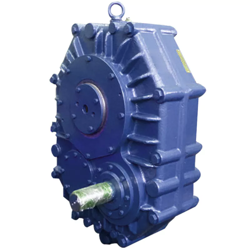
Are there any disadvantages or limitations to using gear reducer systems?
While gear reducer systems offer numerous advantages, they also come with certain disadvantages and limitations that should be considered during the selection and implementation process:
1. Size and Weight: Gear reducers can be bulky and heavy, especially for applications requiring high gear ratios. This can impact the overall size and weight of the machinery or equipment, which may be a concern in space-constrained environments.
2. Efficiency Loss: Despite their high efficiency, gear reducers can experience energy losses due to friction between gear teeth and other components. This can lead to a reduction in overall system efficiency, particularly in cases where multiple gear stages are used.
3. Cost: The design, manufacturing, and assembly of gear reducers can involve complex processes and precision machining, which can contribute to higher initial costs compared to other power transmission solutions.
4. Maintenance: Gear reducer systems require regular maintenance, including lubrication, inspection, and potential gear replacement over time. Maintenance activities can lead to downtime and associated costs in industrial settings.
5. Noise and Vibration: Gear reducers can generate noise and vibrations, especially at high speeds or when operating under heavy loads. Additional measures may be needed to mitigate noise and vibration issues.
6. Limited Gear Ratios: While gear reducers offer a wide range of gear ratios, there may be limitations in achieving extremely high or low ratios in certain designs.
7. Temperature Sensitivity: Extreme temperatures can affect the performance of gear reducer systems, particularly if inadequate lubrication or cooling is provided.
8. Shock Loads: While gear reducers are designed to handle shock loads to some extent, severe shock loads or abrupt changes in torque can still lead to potential damage or premature wear.
Despite these limitations, gear reducer systems remain widely used and versatile components in various industries, and their disadvantages can often be mitigated through proper design, selection, and maintenance practices.
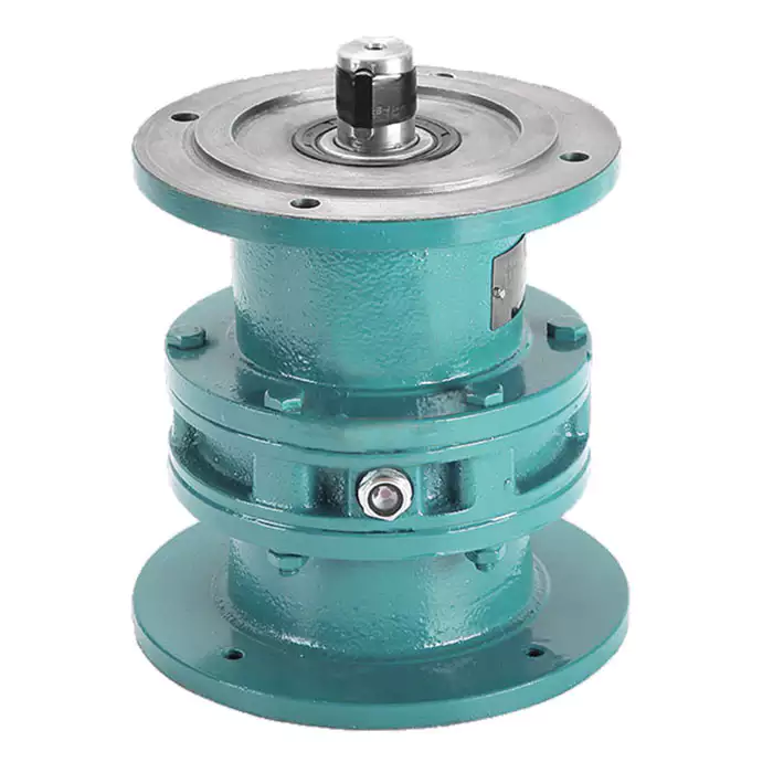
How do gear reducers handle shock loads and sudden changes in torque?
Gear reducers are designed to handle shock loads and sudden changes in torque through several mechanisms that enhance their durability and reliability in challenging operating conditions.
1. Robust Construction: Gear reducers are constructed using high-strength materials and precision manufacturing techniques. This ensures that the gears, bearings, and other components can withstand sudden impacts and high torque fluctuations without deformation or failure.
2. Shock-Absorbing Features: Some gear reducer designs incorporate shock-absorbing features, such as flexible couplings, elastomeric elements, or torsionally flexible gear designs. These features help dampen and dissipate the energy from sudden shocks or torque spikes, reducing the impact on the entire system.
3. Torque Limiters: In applications where shock loads are common, torque limiters may be integrated into the gear reducer. These devices automatically disengage or slip when a certain torque threshold is exceeded, preventing damage to the gears and other components.
4. Overload Protection: Gear reducers can be equipped with overload protection mechanisms, such as shear pins or torque sensors. These mechanisms detect excessive torque and disengage the drive temporarily, allowing the system to absorb the shock or adjust to the sudden torque change.
5. Proper Lubrication: Adequate lubrication is essential for managing shock loads and sudden torque changes. High-quality lubricants reduce friction and wear, helping the gear reducer withstand dynamic forces and maintain smooth operation.
6. Dynamic Load Distribution: Gear reducers distribute dynamic loads across multiple gear teeth, which helps prevent localized stress concentrations. This feature minimizes the risk of tooth breakage and gear damage when subjected to sudden changes in torque.
By incorporating these design features and mechanisms, gear reducers can effectively handle shock loads and sudden changes in torque, ensuring the longevity and reliability of various industrial and mechanical systems.
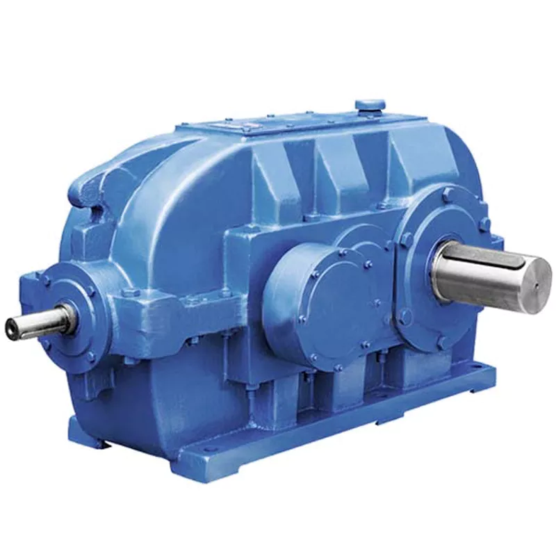
How do gear reducers handle variations in input and output speeds?
Gear reducers are designed to handle variations in input and output speeds through the use of different gear ratios and configurations. They achieve this by utilizing intermeshing gears of varying sizes to transmit torque and control rotational speed.
The basic principle involves connecting two or more gears with different numbers of teeth. When a larger gear (driving gear) engages with a smaller gear (driven gear), the rotational speed of the driven gear decreases while the torque increases. This reduction in speed and increase in torque enable gear reducers to efficiently adapt to variations in input and output speeds.
The gear ratio is a critical factor in determining how much the speed and torque change. It is calculated by dividing the number of teeth on the driven gear by the number of teeth on the driving gear. A higher gear ratio results in a greater reduction in speed and a proportionate increase in torque.
Planetary gear reducers, a common type, use a combination of gears including sun gears, planet gears, and ring gears to achieve different speed reductions and torque enhancements. This design provides versatility in handling variations in speed and torque requirements.
In summary, gear reducers handle variations in input and output speeds by using specific gear ratios and gear arrangements that enable them to efficiently transmit power and control motion characteristics according to the application's needs.


editor by CX 2024-02-09
China factory Nmrv Worm Gear Speed Reducer Double Output Shaft with Motor comer gearbox
Product Description
Product Description
NMRV series worm gear reducer
1. Aluminum alloy housing, small size, light weight.
2. High transmission efficiency, low noise.
3.Smooth ruuning, high output torque and long service life.
4. Multiple connection structure and installation.
| TYPE | Worm Gear Speed Reducer / Worm Gearbox |
| NMRV MODEL | NMRV25, NMRV30, NMRV40, NMRV50, NMRV63, NMRV75, NMRV90, NMRV110, NMRV130, NMRV150 |
| NRV MODEL | NRV25, NRV30, NRV40, NRV50, NRV63, NRV75, NRV90, NRV110, NRV130, NRV150 |
| POWER | 0.12kw-15kw |
| RATIO | 1/7.5,1/10,1/15,1/20,1/15,1/30,1/40,1/50,1/60,1/80,1/100 |
| COLOR | Blue(RAL5571), Silver grey (RAL9571), or on request |
| MATERIAL | Housing/Flange:Aluminum Alloy |
| Worm Gear:Copper 9-4&nodular iron | |
| Worm:20CrMn Ti with carburizing and quenching, surface harness is 56-62HRC | |
| Shaft:chromium steel-45# | |
| IEC FLANGE | IEC standard flange 56B14, 63B14, 63B5, 63B5, 71B14,80B14 AND SO ON |
| LUBRICANT | Synthetic & Mineral |
Detailed Photos
|
NMRV Model&marker |
|||
|
NMRV-063-30-VS-F1(FA)-AS-80B5-0.75KW-B3 |
|||
|
NMRV |
Means hole-input with flange |
||
|
NRV |
Means shaft-input without flange |
||
|
63 |
Centre-to-centre spacing of worm-gear speed reducer |
||
|
30 |
Ratio |
||
|
VS |
Double input shaft |
F1 (FA) |
Flange output |
|
AS |
Single output shaft |
AB |
Double output shaft |
|
PAM |
Fitted for motor coupling |
80B5 |
Motor mounting facility |
|
0.75kw |
Electric motor power |
B3 |
Mounting position |
NMRV NMRV+NMRV
NMRV/NRV ASSEMBLE WITH ELECTRIC MOTOR
Workshop
Manufacturing the Aluminum Housing by CNC. Lots of housings in stock.
Lots of worm gears and worm shafts in stock.
Assembling line
Packaging & Shipping
Each reducer in single carton box packed.
FAQ
Q1: Are you trading company or manufacturer ?
A: We are factory.
Q2: How long is your delivery time and shipment?
1.Sample Lead-times: 10-20 days.
2.Production Lead-times: 30-45 days after order confirmed.
Q3: What is your advantages?
1. The most competitive price and good quality.
2. Perfect technical engineers give you the best support.
3. OEM is available.
/* March 10, 2571 17:59:20 */!function(){function s(e,r){var a,o={};try{e&&e.split(",").forEach(function(e,t){e&&(a=e.match(/(.*?):(.*)$/))&&1
| Application: | Motor, Motorcycle, Machinery, Toy, Agricultural Machinery |
|---|---|
| Hardness: | Hardened Tooth Surface |
| Installation: | Vertical Type |
| Layout: | Coaxial |
| Gear Shape: | Worm Gear |
| Type: | Worm Reducer |
| Customization: |
Available
| Customized Request |
|---|
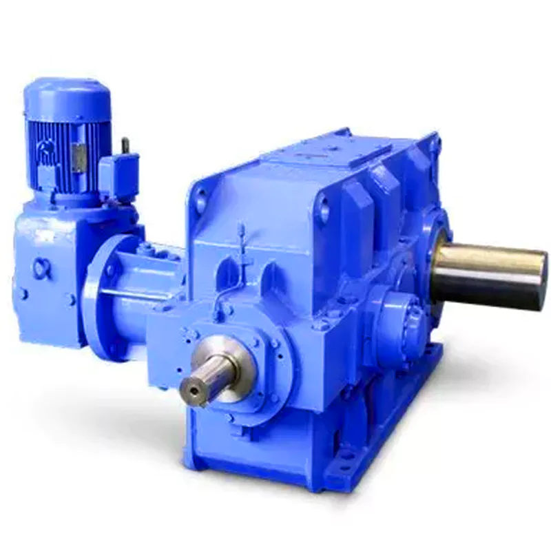
What are the considerations for choosing the appropriate lubrication for gear reducers?
Choosing the appropriate lubrication for gear reducers is crucial for ensuring optimal performance, longevity, and efficiency. Several considerations should be taken into account when selecting the right lubrication:
1. Load and Torque: The magnitude of the load and torque transmitted by the gear reducer affects the lubrication's viscosity and film strength requirements. Heavier loads may necessitate higher viscosity lubricants.
2. Operating Speed: The speed at which the gear reducer operates impacts the lubrication's ability to maintain a consistent and protective film between gear surfaces.
3. Temperature Range: Consider the temperature range of the operating environment. Lubricants with suitable viscosity indexes are crucial to maintaining performance under varying temperature conditions.
4. Contaminant Exposure: If the gear reducer is exposed to dust, dirt, water, or other contaminants, the lubrication should have proper sealing properties and resistance to contamination.
5. Lubrication Interval: Determine the desired maintenance interval. Some lubricants require more frequent replacement, while others offer extended operational periods.
6. Compatibility with Materials: Ensure that the chosen lubricant is compatible with the materials used in the gear reducer, including gears, bearings, and seals.
7. Noise and Vibration: Some lubricants have properties that can help reduce noise and dampen vibrations, improving the overall user experience.
8. Environmental Impact: Consider environmental regulations and sustainability goals when selecting lubricants.
9. Manufacturer Recommendations: Follow the manufacturer's recommendations and guidelines for lubrication type, viscosity grade, and maintenance intervals.
10. Monitoring and Analysis: Implement a lubrication monitoring and analysis program to assess lubricant condition and performance over time.
By carefully evaluating these considerations and consulting with lubrication experts, industries can choose the most suitable lubrication for their gear reducers, ensuring reliable and efficient operation.
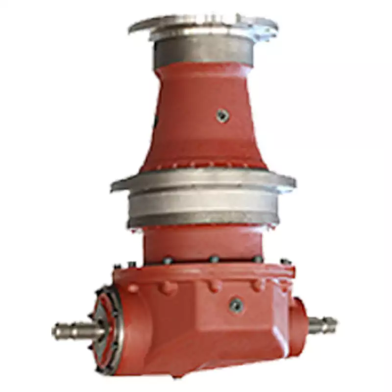
What maintenance practices are essential for prolonging the lifespan of gear reducers?
Proper maintenance is crucial for extending the lifespan and ensuring optimal performance of gear reducers. Here are essential maintenance practices:
- 1. Lubrication: Regular lubrication of gear reducers is vital to reduce friction, wear, and heat generation. Use the recommended lubricant and follow the manufacturer's guidelines for lubrication intervals.
- 2. Inspection: Routinely inspect gear reducers for signs of wear, damage, or leaks. Check for unusual noises, vibrations, or temperature increases during operation.
- 3. Alignment: Ensure proper alignment of the input and output shafts. Misalignment can lead to increased wear, noise, and reduced efficiency. Align the components according to the manufacturer's specifications.
- 4. Cooling and Ventilation: Maintain proper cooling and ventilation to prevent overheating. Ensure that cooling fans and vents are clean and unobstructed.
- 5. Seal Maintenance: Inspect and replace seals as needed to prevent contaminants from entering the gear reducer. Contaminants can lead to accelerated wear and reduced performance.
- 6. Bolts and Fasteners: Regularly check and tighten bolts and fasteners to prevent loosening during operation, which can cause misalignment or component damage.
- 7. Replacing Worn Components: Replace worn or damaged components, such as gears, bearings, and seals, with genuine parts from the manufacturer.
- 8. Vibration Analysis: Conduct periodic vibration analysis to identify potential issues early. Excessive vibration can indicate misalignment or component wear.
- 9. Maintenance Records: Keep detailed maintenance records, including lubrication schedules, inspection dates, and component replacements. This helps track the history of the gear reducer and aids in future maintenance planning.
- 10. Training: Provide proper training to maintenance personnel on gear reducer maintenance and troubleshooting techniques.
By adhering to these maintenance practices, you can maximize the lifespan of your gear reducers, minimize downtime, and ensure reliable operation in your industrial processes.

How do gear reducers handle variations in input and output speeds?
Gear reducers are designed to handle variations in input and output speeds through the use of different gear ratios and configurations. They achieve this by utilizing intermeshing gears of varying sizes to transmit torque and control rotational speed.
The basic principle involves connecting two or more gears with different numbers of teeth. When a larger gear (driving gear) engages with a smaller gear (driven gear), the rotational speed of the driven gear decreases while the torque increases. This reduction in speed and increase in torque enable gear reducers to efficiently adapt to variations in input and output speeds.
The gear ratio is a critical factor in determining how much the speed and torque change. It is calculated by dividing the number of teeth on the driven gear by the number of teeth on the driving gear. A higher gear ratio results in a greater reduction in speed and a proportionate increase in torque.
Planetary gear reducers, a common type, use a combination of gears including sun gears, planet gears, and ring gears to achieve different speed reductions and torque enhancements. This design provides versatility in handling variations in speed and torque requirements.
In summary, gear reducers handle variations in input and output speeds by using specific gear ratios and gear arrangements that enable them to efficiently transmit power and control motion characteristics according to the application's needs.


editor by CX 2023-12-20
China Best Sales CZPT Shaft Output S Series Helical Worm Gearbox with Motor gearbox assembly
Product Description
Solid Shaft Output S Series Helical Worm Gearbox with Motor
1.Technical data
| Input power | Ratio | Input speed | Torque | Transmission stage | Mounting type |
| 0.18~22kW | 9.96~244.74(MAX:4606) | 1400rpm 900rpm 700rpm |
90~4000N.m | 2stage 3stage |
Foot mounted Flange mounted |
2.Input power rating and permissible torque
| Size | 37 | 47 | 57 | 67 | 77 | 87 | 97 |
| Structure | S SA SF SAF SAT SAZ | ||||||
| Input Power(kW) | 0.18~0.75 | 0.18~1.5 | 0.18~3 | 0.25~5.5 | 0.55~7.5 | 0.75~15 | 1.5~22 |
| Ratio | 10.27~165.71 | 11.46~244.74 | 10.78~196.21 | 11.55~227.20 | 9.96~241.09 | 11.83~223.26 | 12.75~230.48 |
| Permissible Torque(N.m) | 90 | 170 | 300 | 520 | 1270 | 2280 | 4000 |
3.Gear unit weight
| Size | 37 | 47 | 57 | 67 | 77 | 87 | 97 |
| Weight(kg) | 7 | 10 | 14 | 26 | 50 | 100 | 170 |
4.Structures of S series gearbox
| S series gear units are available in the following designs | |
| S...Y... | Foot-mounted parallel shaft helical gear units with solid shaft |
| SA...Y... | Parallel shaft helical gear units with hollow shaft |
| SAZ...Y... | Short-flange mounted parallel shaft helical gear units with hollow shaft |
| SF...Y... | Flange-mounted parallel shaft helical gear units with solid shaft |
| SAT...Y... | Flange-mounted parallel shaft helical gear units with hollow shaft |
| S(SF,SA,SAF,SAZ)S... | Shaft input parallel shaft helical gear units |
| S(SF,SA,SAF,SAZ)...R...Y... | Combinatorial parallel shaft helical gear units |
| S(SF,SA,SAF,SAZ)S...R... | Shaft input combinatorial parallel shaft helical gear units |
5.Field Gear Box's Usage
1. Metallurgy 2 Mine 3 Machine 4 Energy 5 Transportation 6 Water Conserbancy 7 Tomacco 8 Pharmacy 9 Printing Package 10 Chemical industry...
6.Our services:
| Pre-sale services | 1. Select equipment model. |
| 2.Design and manufacture products according to clients' special requirement. | |
| 3.Train technical personal for clients | |
| Services during selling | 1.Pre-check and accept products ahead of delivery. |
| 2. Help clients to draft solving plans. | |
| After-sale services | 1.Assist clients to prepare for the first construction scheme. |
| 2. Train the first-line operators. | |
| 3.Take initiative to eliminate the trouble rapidly. | |
| 4. Provide technical exchanging. |
7.S series gearbox are available in the following designs:
(1) SY
Foot mounted helical worm gearbox with CHINAMFG shaft
(2) SAY
Helical worm gearbox with hollow shaft
(3) SAZY
Small flange mounted helical worm gearbox with hollow shaft
(4) SA (S,SF,SAF,SAZ)Y
Assemble users' motor or special motor, flange is required
(5) SFY
Flange mounted helical worm gearbox with CHINAMFG shaft
(6) SAFY
Flange mounted helical worm gearbox with hollow shaft
(7) SATY
Torque arm mounted helical worm gearbox with hollow shaft
(8) S (SF,SA,SAF,SAZ) S
Shaft input helical worm gearbox
(9) SA (S,SF,SAF,SAZ)RY
Combined helical worm gearbox
(10) SA (S,SF,SAF,SAZ)SR
Shaft input combined helical worm gearbox
8.Product picture:
9.Our company :
AOKMAN was founded in 1982, which has more than 36 years in R & D and manufacturing of gearboxes, gears, shaft, motor and spare parts.
We can offer the proper solution for uncountable applications. Our products are widely used in the ranges of metallurgical, steel, mining, pulp and paper, sugar and alcohol market and various other types of machines with a strong presence in the international market.
AOKMAN has become a reliable supplier, able to supply high quality gearboxes.With 36 years experience, we assure you the utmost reliability and security for both product and services.
10.Customer visiting:
11.FAQ:
1.Q:What kinds of gearbox can you produce for us?
A:Main products of our company: UDL series speed variator,RV series worm gear reducer, ATA series shaft mounted gearbox, X,B series gear reducer,
P series planetary gearbox and R, S, K, and F series helical-tooth reducer, more
than 1 hundred models and thousands of specifications
2.Q:Can you make as per custom drawing?
A: Yes, we offer customized service for customers.
3.Q:What is your terms of payment ?
A: 30% Advance payment by T/T after signing the contract.70% before delivery
4.Q:What is your MOQ?
A: 1 Set
If you are interested in our product, welcome you contact me.
Our team will support any need you might have.
| Application: | Motor, Machinery, Industry |
|---|---|
| Function: | Change Drive Torque, Speed Changing, Speed Reduction |
| Layout: | Right Angle |
| Hardness: | Hardened Tooth Surface |
| Installation: | Horizontal Type |
| Step: | Double-Step |
| Customization: |
Available
| Customized Request |
|---|
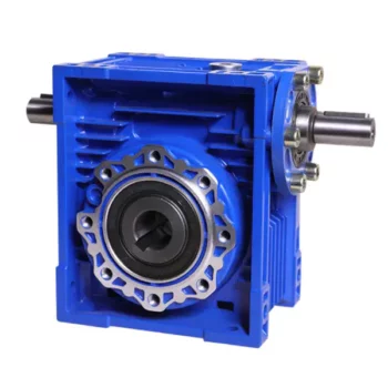
What are the Noise Levels Associated with Worm Gearboxes?
The noise levels associated with worm gearboxes can vary depending on several factors, including the design, quality, operating conditions, and maintenance of the gearbox. Here are some key points to consider:
- Design and Quality: Well-designed and high-quality worm gearboxes tend to produce lower noise levels. Factors such as gear tooth profile, precision manufacturing, and proper alignment can contribute to reduced noise.
- Gear Engagement: The way the worm and worm wheel engage and mesh with each other can impact noise levels. Proper tooth contact and alignment can help minimize noise during operation.
- Lubrication: Inadequate or improper lubrication can lead to increased friction and wear, resulting in higher noise levels. Using the recommended lubricant and maintaining proper lubrication levels are important for noise reduction.
- Operating Conditions: Operating the gearbox within its specified load and speed limits can help prevent excessive noise generation. Overloading or operating at high speeds beyond the gearbox's capabilities can lead to increased noise.
- Backlash: Excessive backlash or play between the gear teeth can lead to impact noise as the teeth engage. Proper backlash adjustment can help mitigate this issue.
- Maintenance: Regular maintenance, including gear inspection, lubrication checks, and addressing any wear or damage, can help keep noise levels in check.
It's important to note that while worm gearboxes can produce some noise due to the nature of gear meshing, proper design, maintenance, and operation can significantly reduce noise levels. If noise is a concern for your application, consulting with gearbox manufacturers and experts can provide insights into selecting the right gearbox type and implementing measures to minimize noise.
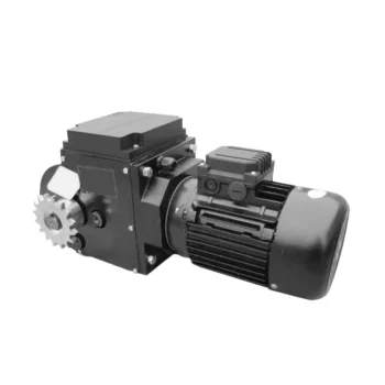
Worm Gearbox Applications in Robotics and Automation
Worm gearboxes play a crucial role in various robotics and automation applications due to their unique characteristics and benefits. Here are some common applications where worm gearboxes are used:
- Robotic Arm Movement: Worm gearboxes are employed in robotic arms to provide precise and controlled movement. The self-locking property of worm gearboxes helps maintain the arm's position without requiring additional brakes.
- Conveyor Systems: In automated production lines, worm gearboxes are used to drive conveyor belts and move materials or products along assembly lines with accuracy.
- Precision Positioning: Worm gearboxes are used in precision positioning systems, such as those found in pick-and-place robots and CNC machines. They ensure accurate and repeatable movements.
- Pan and Tilt Mechanisms: Worm gearboxes are utilized in pan and tilt mechanisms of surveillance cameras, robotic cameras, and sensors. The self-locking feature helps stabilize and maintain the desired angle.
- Automated Gates and Doors: Worm gearboxes are used in automated gate and door systems to control their opening and closing movements smoothly and safely.
- Material Handling: Robots in warehouses and distribution centers use worm gearboxes to manipulate and lift objects, enhancing efficiency in material handling.
- Medical Robotics: Worm gearboxes are employed in medical robots for surgical procedures, diagnostic equipment, and rehabilitation devices, ensuring precise and controlled movements.
- Industrial Robots: Industrial robots rely on worm gearboxes for various tasks, including welding, painting, assembly, and packaging, where precise movements are essential.
- Automated Testing Equipment: In testing and inspection applications, worm gearboxes provide the necessary movement and positioning for accurate testing and measurements.
- Food and Beverage Industry: Worm gearboxes are used in automated food processing and packaging systems, ensuring hygienic and precise movement of products.
Worm gearboxes are preferred in these applications due to their compact size, high torque output, self-locking feature, and ability to provide a right-angle drive. However, selecting the right gearbox requires considering factors such as load, speed, efficiency, and environmental conditions.

What is a Worm Gearbox and How Does It Work?
A worm gearbox, also known as a worm gear reducer, is a mechanical device used to transmit rotational motion and torque between non-parallel shafts. It consists of a worm screw and a worm wheel, both of which have helical teeth. The worm screw resembles a threaded cylinder, while the worm wheel is a gear with teeth that mesh with the worm screw.
The working principle of a worm gearbox involves the interaction between the worm screw and the worm wheel. When the worm screw is rotated, its helical teeth engage with the teeth of the worm wheel. As the worm screw rotates, it translates the rotational motion into a perpendicular motion, causing the worm wheel to rotate. This perpendicular motion allows the worm gearbox to achieve a high gear reduction ratio, making it suitable for applications that require significant speed reduction.
One of the key features of a worm gearbox is its ability to provide a high gear reduction ratio in a compact design. However, due to the sliding nature of the meshing teeth, worm gearboxes may exhibit higher friction and lower efficiency compared to other types of gearboxes. Therefore, they are often used in applications where efficiency is not the primary concern but where high torque and speed reduction are essential, such as conveyor systems, elevators, automotive steering systems, and certain industrial machinery.


editor by CX 2023-09-15
China Custom Drive Generator Tractor Cardan Adapter Output Assembly Hexagon Pto Shaft
Product Description
| Part Name: | Hexagon PTO Shaft |
| Type: | Hexagon PTO Shaft |
| Industry Focus: | Agricultural |
| Application: | Engineering Machinery Engine |
| Performance: | High Precision |
| Feature: | Flawless finish High durability Sturdiness Product Image |
| Factory Add: |
Tiller Blade Plant : Xihu (West Lake) Dis.ng hardware industrial park, Xihu (West Lake) Dis. district, ZheJiang . Disc Blade Plant : HangZhou hi-tech development zone, HangZhou, ZheJiang . Iron Wheel Plant : Xihu (West Lake) Dis. Tongqin Town, HangZhou, zHangZhoug. Bolt and Nut Plant : Xihu (West Lake) Dis. industrial zone, HangZhou, zHangZhoug. |
| If you have any enquiry about quotation or cooperation, please feel free to email us, Our sales representative will contact you within 24 hours. Thank you for your interest in our products. | |
CLICK HERE YOU CAN
Back To Homepage
View more products about Pto Shaft
Why choose FarmDiscover for cooperation?
Comparing with our competitors, we have much more advantages as follows:
1.Since 2000 we have been exporting our parts and have rich experience in agriculture parts export.
2. More professional sales staffs to guarantee the better service.
3. Close to HangZhou/ZheJiang port, Reduce the transportation cost and time, ensure timely delivery.
4. Better quality to guarantee better Credit.
| Material: | Alloy Steel |
|---|---|
| Load: | Drive Shaft |
| Stiffness & Flexibility: | Stiffness / Rigid Axle |
| Journal Diameter Dimensional Accuracy: | Standard |
| Axis Shape: | Straight Shaft |
| Shaft Shape: | Real Axis |
| Customization: |
Available
| Customized Request |
|---|

What maintenance practices are essential for prolonging the lifespan of PTO shafts?
Maintaining proper care and performing regular maintenance on Power Take-Off (PTO) shafts is crucial for prolonging their lifespan and ensuring optimal performance. By following essential maintenance practices, you can prevent premature wear, identify potential issues early on, and maximize the longevity of your PTO shafts. Here are some key maintenance practices to consider:
1. Regular Inspection: Perform routine visual inspections of the PTO shaft to check for any signs of damage, wear, or misalignment. Look for cracks, dents, bent sections, or loose components. Inspect the universal joints, coupling mechanisms, protective guards, and other associated parts. Pay attention to any unusual noises, vibrations, or changes in performance, as these can indicate underlying issues that require attention.
2. Lubrication: Proper lubrication is essential for the smooth operation and longevity of PTO shafts. Follow the manufacturer's recommendations regarding lubrication intervals and use the recommended lubricant type. Apply lubrication to the universal joints, CV joints (if applicable), and other moving parts as specified. Regularly check for adequate lubricant levels and replenish if necessary. Ensure that the lubricant used is compatible with the shaft material and does not attract dirt or debris that could cause abrasion or damage.
3. Cleaning: Keep the PTO shaft clean and free from dirt, debris, and other contaminants. Regularly remove any accumulated dirt, grease, or residue using a brush or compressed air. Be particularly diligent in cleaning the universal joints and areas where the shaft connects to other components. Cleaning prevents the buildup of abrasive particles that can accelerate wear and compromise the shaft's performance.
4. Guard Inspection and Maintenance: Check the protective guards and shields regularly to ensure they are securely in place and free from damage. Guards play a critical role in preventing accidental contact with the rotating shaft and minimizing the risk of injury. Repair or replace any damaged or missing guards promptly. Ensure that the guards are correctly aligned and provide sufficient coverage for all moving parts of the PTO shaft.
5. Torque and Fastener Checks: Periodically inspect and check the torque of fasteners, such as bolts and nuts, that secure the PTO shaft and associated components. Over time, vibration and normal operation can loosen these fasteners, compromising the integrity of the shaft. Use the appropriate torque specifications provided by the manufacturer to ensure proper tightening. Regularly verify the tightness of fasteners and retighten as necessary.
6. Shear Bolt or Slip Clutch Maintenance: If your PTO shaft incorporates shear bolt or slip clutch mechanisms, ensure they are functioning correctly. Inspect the shear bolts for signs of wear or damage, and replace them when necessary. Check the slip clutch for proper adjustment and smooth operation. Follow the manufacturer's recommendations regarding maintenance and adjustment of these safety mechanisms to ensure their effectiveness in protecting the driveline components.
7. Proper Storage: When the PTO shaft is not in use, store it in a clean and dry environment. Protect the shaft from exposure to moisture, extreme temperatures, and corrosive substances. If possible, store the shaft in a vertical position to prevent bending or distortion. Consider using protective covers or cases to shield the shaft from dust, dirt, and other potential sources of damage.
8. Operator Training: Provide proper training to operators on the correct operation, maintenance, and safety procedures related to the PTO shafts. Educate them about the importance of regular inspections, lubrication, and adherence to recommended maintenance practices. Encourage operators to report any abnormalities or concerns promptly to prevent further damage and ensure timely repairs or adjustments.
9. Manufacturer and Expert Guidance: Consult the manufacturer's guidelines and recommendations regarding maintenance practices specific to your PTO shaft model. Additionally, seek advice from experts or authorized service technicians who are knowledgeable about PTO shaft maintenance. They can provide valuable insights and assistance in implementing the best maintenance practices for your specific PTO shafts.
By following these maintenance practices, you can extend the lifespan of your PTO shafts, optimize their performance, and reduce the likelihood of unexpected failures or costly repairs. Regular inspections, lubrication, cleaning, guard maintenance, torque checks, and proper storage are all essential in ensuring the longevity and reliability of your PTO shafts.

How do PTO shafts enhance the performance of tractors and agricultural machinery?
Power Take-Off (PTO) shafts play a crucial role in enhancing the performance of tractors and agricultural machinery. By providing a reliable power transfer mechanism, PTO shafts enable these machines to operate efficiently, effectively, and with increased versatility. Here's a detailed explanation of how PTO shafts enhance the performance of tractors and agricultural machinery:
1. Power Transfer: PTO shafts facilitate the transfer of power from the tractor's engine to various agricultural implements and machinery. The rotating power generated by the engine is transmitted through the PTO shaft to drive the connected equipment. This direct power transfer eliminates the need for separate engines or motors on each implement, reducing complexity, weight, and maintenance requirements. PTO shafts ensure a consistent and reliable power supply, enabling agricultural machinery to perform tasks with optimal efficiency and effectiveness.
2. Versatility: PTO shafts provide tractors and agricultural machinery with increased versatility. Since PTO shafts have standardized dimensions and connection methods, a wide range of implements can be easily attached and powered by the same tractor. This versatility allows farmers to quickly switch between different tasks, such as mowing, tilling, planting, and harvesting, without the need for multiple specialized machines. The ability to use a single power unit for various operations reduces costs, saves storage space, and improves overall operational efficiency.
3. Improved Productivity: PTO shafts contribute to improved productivity in agricultural operations. By harnessing the power of tractors, agricultural machinery can operate at higher speeds and with greater efficiency compared to manual or alternative power methods. PTO-driven implements, such as mowers, balers, and harvesters, can cover larger areas and complete tasks more quickly, reducing the time required to perform agricultural operations. This increased productivity allows farmers to accomplish more within a given timeframe, leading to higher crop yields and improved overall farm efficiency.
4. Reduced Labor Requirements: PTO shafts help reduce labor requirements in agricultural operations. By utilizing mechanized equipment powered by PTO shafts, farmers can minimize manual labor and the associated physical effort. Tasks such as plowing, tilling, and harvesting can be performed more efficiently and with less reliance on human labor. This reduction in labor requirements allows farmers to allocate resources more effectively, focus on other essential tasks, and potentially reduce labor costs.
5. Precision and Accuracy: PTO shafts contribute to precision and accuracy in agricultural operations. The consistent power supply from the tractor's engine ensures uniform operation and performance of the connected machinery. This precision is crucial for tasks such as seed placement, fertilizer or chemical application, and crop harvesting. PTO-driven equipment can provide consistent rotations per minute (RPM) and maintain the necessary operational parameters, resulting in precise and accurate agricultural practices. This precision leads to improved crop quality, reduced waste, and optimized resource utilization.
6. Adaptability to Various Tasks: PTO shafts enhance the adaptability of tractors and agricultural machinery to perform various tasks. With the ability to connect different implements, such as mowers, seeders, sprayers, or balers, via PTO shafts, farmers can quickly transform their tractors into specialized machines for specific operations. This adaptability allows for efficient utilization of equipment across different stages of crop production, enabling farmers to respond to changing needs and conditions in a cost-effective manner.
7. Enhanced Safety: PTO shafts contribute to enhanced safety in agricultural operations. Many PTO shafts are equipped with safety features, such as shields or guards, to protect operators from potential hazards associated with rotating components. These safety measures help prevent entanglement accidents and reduce the risk of injuries. Additionally, by using PTO-driven machinery, farmers can keep a safe distance from certain hazardous tasks, such as mowing or shredding, further improving overall safety on the farm.
8. Integration with Technology: PTO shafts can be integrated with advanced technology and automation systems in modern tractors and agricultural machinery. This integration allows for precise control, data monitoring, and optimization of machine performance. For example, precision guidance systems can be synchronized with PTO-driven implements to ensure accurate seed placement or chemical application. Furthermore, data collection and analysis can provide insights into fuel efficiency, maintenance needs, and overall equipment performance, leading to optimized operation and improved productivity.
In summary, PTO shafts enhance the performance of tractors and agricultural machinery by enabling efficient power transfer, increasing versatility, improving productivity, reducing labor requirements, ensuring precision and accuracy, facilitating adaptability, enhancing safety, and integrating with advanced technologies. These benefits contribute to overall operational efficiency, cost-effectiveness, and the ability of farmers to effectively manage theiragricultural operations.
What is a PTO shaft and how is it used in agricultural and industrial equipment?
A power take-off (PTO) shaft is a mechanical component used in agricultural and industrial equipment to transfer power from a power source, such as an engine or motor, to another machine or implement. It is a driveline shaft that transmits rotational power and torque, allowing the connected equipment to perform various tasks. PTO shafts are commonly used in agricultural machinery, such as tractors, as well as in industrial equipment, including generators, pumps, and construction machinery. Here's a detailed explanation of what a PTO shaft is and how it is used:
Structure and Components: A typical PTO shaft consists of a hollow metal tube with universal joints at each end. The hollow tube allows the shaft to rotate freely, while the universal joints accommodate angular misalignments between the power source and the driven equipment. The universal joints consist of a cross-shaped yoke with needle bearings, providing flexibility and allowing the transmission of power at varying angles. Some PTO shafts may also include a telescopic section to adjust the length for different equipment setups or to accommodate varying distances between the power source and the driven machine.
Power Transfer: The primary function of a PTO shaft is to transfer power and torque from the power source to the driven equipment. The power source, typically an engine or motor, drives the PTO shaft through a mechanical connection, such as a gearbox or a clutch. As the power source rotates, it transmits rotational force to the PTO shaft. The PTO shaft, in turn, transfers this rotational power and torque to the driven equipment, enabling it to perform its intended function. The torque and rotational speed transmitted through the PTO shaft depend on the power source's characteristics and the gear ratio or clutch engagement.
Agricultural Applications: In agriculture, PTO shafts are commonly used in tractors to power various implements and attachments. The PTO shaft is connected to the tractor's power take-off, a rotating drive shaft located at the rear of the tractor. By engaging the PTO clutch, the tractor's engine power is transferred through the PTO shaft to the attached implements. Agricultural machinery, such as mowers, balers, tillers, sprayers, and grain augers, often rely on PTO shafts to receive power for their operation. The PTO shaft allows the implements to be powered directly by the tractor's engine, eliminating the need for separate power sources and increasing the versatility and efficiency of agricultural operations.
Industrial Applications: PTO shafts also find extensive use in various industrial applications. Industrial equipment, such as generators, pumps, compressors, and industrial mixers, often incorporate PTO shafts to receive power from engines or electric motors. The PTO shaft connects the power source to the driven equipment, allowing it to operate and perform its intended function. In construction machinery, PTO shafts can be found in equipment like concrete mixers, hydraulic hammers, and post hole diggers, enabling the transfer of power from the machinery's engine to the specific attachment or tool being used.
Safety Considerations: It is important to note that PTO shafts can pose safety risks if not handled properly. The rotating shaft can cause serious injuries if operators come into contact with it while it is in operation. To ensure safety, PTO shafts are often equipped with shielding or guards that cover the rotating shaft and universal joints, preventing accidental contact. It is crucial to maintain and inspect these safety features regularly to ensure their effectiveness. Additionally, operators should receive proper training on PTO shaft operation, including safe attachment and detachment procedures, as well as the use of personal protective equipment when working near PTO-driven machinery.
In summary, a PTO shaft is a mechanical component used in agricultural and industrial equipment to transmit power and torque from a power source to a driven machine or implement. It enables the direct power transfer from engines or motors to various equipment, increasing efficiency and versatility in agricultural and industrial operations. While PTO shafts offer significant benefits, operators must be aware of the associated safety considerations and take appropriate precautions to prevent accidents and injuries.


editor by CX 2023-09-14