Product Description
Product Description
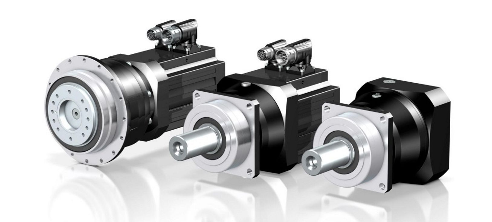
High Motion Accuracy Stainless Reducer Servo Gearbox WABseries for 15mm Shaft Servomotor FuBao
Stainless reducer servo gearbox is a new generation of practical products independently developed by our company:
Low noise: less than 65db.
Low back clearance: up to 3 arc minutes in a CHINAMFG and 5 arc minutes in a double stage.
High torque: higher than the standard planetary reducer torque.
High stability: high strength alloy steel, the whole gear after hardening treatment, not only the surface hard substitution.
High deceleration ratio: Modular design, planetary gearbox can be interlinked.
Stainless reducer servo gearbox characteristic:
1.Planetary reducer manufacturer-Fubao Electromechanical Technology adopts an integrated planetary carrier and output shaft, which can provide better torsional rigidity. After precision machining, the gear set is not easy to eccentric, which can reduce interference, reduce wear and noise, and at the same time use a large The bearings are arranged with a wide span to distribute the load of the bearings, and once again strengthen the torque rigidity and radial load capacity of the gearbox. The output cover is made of aluminum alloy, which provides better heat dissipation capability for the product, so that the reducer produced by Fubao Electromechanical Technology can play an excellent role in the field of mechanical tools.
2.The planetary gear set is specially made of alloy steel. First, it undergoes quenching and tempering heat treatment to make the material hardness reach HRC30 degrees, and then undergoes nitriding surface treatment to HV860, so that the product has the characteristics of high surface hardness and high toughness in the center, and achieves the best product strength and service life. optimization.
3.The input shaft and the motor output shaft are connected by a bolted structure, with a round shaft seal design, and through dynamic balance analysis, it can ensure that there is no eccentric load at high speeds. After reducing unnecessary radial force, it can effectively Reduce the load on the motor side.
4.The material of the input cover/motor connection seat is made of aluminum alloy, which can provide better heat dissipation effect, and then provide good concentricity and verticality through professional lathe processing, so that the product can be stably combined with various motors, reducing the damage caused by insufficient precision. Unnecessary axial radial force makes the product have a longer life cycle.
| WAB series parameters | Model number | WAB042 | WAB60 | WAB090 | WAB115 | WAB140 | WAB180 | WAB220 |
| Rated output torque | 14-22 | 23-60 | 48-160 | 140-330 | 342-650 | 520-1200 | 1140-2000 | |
| Reduction ratio | L1: 3, 4, 5, 6, 7, 8, 9, 10 L2: 15, 20, 25, 30, 35, 40, 50, 70, 80, 100 | |||||||
| Planetary gear backlash | L1: P0≤1 P1≤3 P2≤5 L2: P0≤3 P1≤5 P2≤7 | |||||||
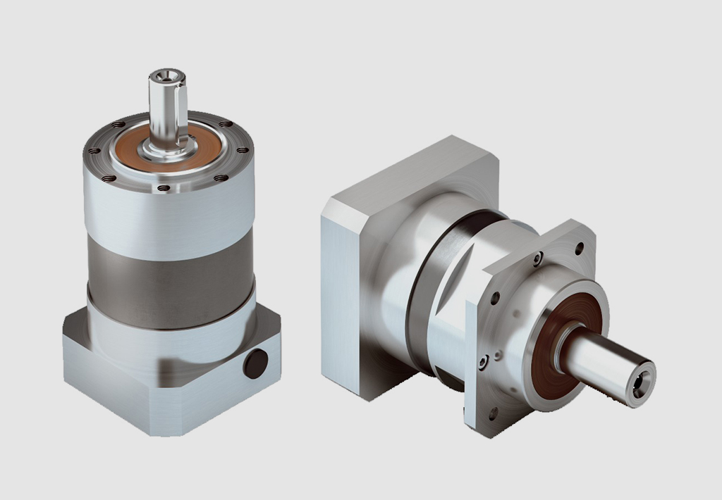
Detailed Photos
Product Details
Other products
Product Advantage
Compared with other reduction machines, planetary gear reduction machines have high rigidity, high precision (single stage can be achieved within 1 point), high transmission efficiency (single stage in 97-98%), high torque/volume ratio, lifetime maintenance free and other characteristics.
Because of these characteristics, planetary gear reducer is mostly installed on the stepper motor and servo motor, used to reduce speed, increase torque, matching inertia.
Company Profile
Factory Display
Q: Speed reducer grease replacement time
A: When sealing appropriate amount of grease and running reducer, the standard replacement time is 20000 hours according to the aging condition of the grease. In addition, when the grease is stained or used in the surrounding temperature condition (above 40ºC), please check the aging and fouling of the grease, and specify the replacement time.
Q: Delivery time
A: Fubao has 2000+ production base, daily output of 1000+ units, standard models within 7 days of delivery.
Q: Reducer selection
A: Fubao provides professional product selection guidance, with higher product matching degree, higher cost performance and higher utilization rate.
Q: Application range of reducer
A: Fubao has a professional research and development team, complete category design, can match any stepping motor, servo motor, more accurate matching.
/* March 10, 2571 17:59:20 */!function(){function s(e,r){var a,o={};try{e&&e.split(",").forEach(function(e,t){e&&(a=e.match(/(.*?):(.*)$/))&&1
| Application: | Motor, Machinery, Agricultural Machinery, Mechanical Equipment |
|---|---|
| Hardness: | Hardened Tooth Surface |
| Installation: | Vertical Type |
| Customization: |
Available
| Customized Request |
|---|
.shipping-cost-tm .tm-status-off{background: none;padding:0;color: #1470cc}
|
Shipping Cost:
Estimated freight per unit. |
about shipping cost and estimated delivery time. |
|---|
| Payment Method: |
|
|---|---|
|
Initial Payment Full Payment |
| Currency: | US$ |
|---|
| Return&refunds: | You can apply for a refund up to 30 days after receipt of the products. |
|---|
Lubrication Practices for Maintaining Servo Gearbox Performance
Proper lubrication is essential for maintaining the performance and longevity of servo gearboxes:
1. High-Quality Lubricants: Selecting the right lubricant is crucial. High-quality lubricants with the appropriate viscosity and additives are chosen based on factors like load, speed, and operating conditions.
2. Lubricant Compatibility: Ensure that the chosen lubricant is compatible with the materials used in the gearbox construction, including seals, bearings, and gears.
3. Regular Lubrication Checks: Regularly inspect the lubricant level and condition. Monitor for signs of contamination, degradation, or overheating.
4. Proper Lubricant Amount: Avoid overfilling or underfilling the gearbox. Follow manufacturer guidelines for the correct lubricant amount to ensure optimal performance.
5. Scheduled Lubrication Intervals: Establish a maintenance schedule for lubricant replacement based on operating hours, usage intensity, and environmental conditions.
6. Lubricant Contamination Prevention: Keep the gearbox environment clean and free from contaminants like dust, dirt, and moisture to prevent lubricant contamination.
7. Lubricant Temperature: Monitor and control the operating temperature of the gearbox to prevent lubricant breakdown and ensure proper viscosity.
8. Re-Greasing: In some cases, re-greasing may be necessary due to lubricant aging or displacement. Follow manufacturer recommendations for re-greasing intervals.
9. Seal Inspection: Check the seals regularly for wear and damage. Damaged seals can lead to lubricant leakage and contamination.
10. Expert Consultation: If unsure about lubricant selection or maintenance procedures, consult with experts or follow manufacturer recommendations.
Proper lubrication practices play a critical role in minimizing friction, reducing wear, and ensuring the efficient operation of servo gearboxes in motion control systems.
Precision of Gear Tooth Profiles in Servo Gearboxes
Manufacturers take several measures to ensure the precision of gear tooth profiles in servo gearboxes:
1. Advanced Manufacturing Processes: Manufacturers use advanced machining techniques such as CNC (Computer Numerical Control) machining and grinding to achieve high precision in gear tooth profiles. These processes allow for accurate shaping and finishing of the gear teeth.
2. Quality Materials: High-quality materials with consistent properties are selected for manufacturing gear components. This ensures uniformity in the gear teeth and minimizes variations that could affect precision.
3. Tight Tolerances: Manufacturers set tight tolerances for gear tooth dimensions, including pitch, profile, and helix angle. This helps to maintain precise engagement between gear teeth, reducing backlash and ensuring accurate motion control.
4. Quality Control: Rigorous quality control measures are implemented at various stages of the manufacturing process. This includes inspections, measurements, and tests to verify that gear tooth profiles meet the required specifications.
5. CNC Gear Inspection: Manufacturers use CNC gear inspection machines that can measure and analyze gear tooth profiles with high accuracy. These machines generate detailed reports about tooth geometry, ensuring compliance with design specifications.
6. Computer-Aided Design (CAD) and Simulation: Manufacturers use CAD software to design gear tooth profiles with precision. Simulation tools analyze how different factors, such as material properties and manufacturing processes, affect the final gear tooth shape.
7. Profile Corrections: In some cases, manufacturers apply profile corrections to optimize gear tooth profiles. These corrections compensate for any deviations that may occur during the manufacturing process.
8. Feedback from Application: Manufacturers often collaborate closely with end-users to gather feedback on the performance of gearboxes in real-world applications. This feedback helps refine the manufacturing process and improve the precision of gear tooth profiles.
The combination of advanced manufacturing techniques, strict quality control, and continuous improvement processes ensures that servo gearboxes maintain the precision required for accurate motion control in various applications.

Role of Servo Gearbox in Robotics and Automation
Servo gearboxes play a crucial role in enhancing the performance and precision of robotics and automation systems:
1. Precision Motion Control: In robotics and automation, precise control of movement is essential. Servo gearboxes provide accurate speed and position control, allowing robots to perform intricate tasks with high accuracy.
2. Efficient Power Transmission: Servo gearboxes efficiently transmit power from the motor to the robotic components, ensuring minimal energy loss and optimizing the overall system efficiency.
3. Dynamic Performance: Robots often require quick changes in direction, speed, and acceleration. Servo gearboxes excel in dynamic performance, enabling rapid adjustments and smooth motion changes.
4. Reducing Backlash: Backlash in gear systems can lead to imprecise movements. Servo gearboxes are designed to minimize backlash, resulting in accurate positioning and reduced lost motion.
5. Compact Design: Many robotic applications require compact and lightweight components. Servo gearboxes offer a high torque-to-size ratio, allowing robots to generate significant power while maintaining a small footprint.
6. Smooth and Silent Operation: The low backlash and precise gearing of servo gearboxes contribute to smooth and quiet operation, which is crucial in environments where noise and vibration can affect performance.
7. Feedback Integration: Servo gearboxes can integrate with various feedback devices, such as encoders, resolvers, and sensors, to provide accurate position and speed information to the control system.
8. Reliable and Repeatable Performance: The consistent and repeatable performance of servo gearboxes ensures that robots can execute tasks accurately and reliably over time.
9. Customization: Servo gearboxes can be customized to meet the specific requirements of different robotic applications, including factors like gear ratios, mounting options, and feedback compatibility.
10. Versatility: From industrial assembly lines to medical robotics, servo gearboxes find applications in a wide range of industries, contributing to improved automation and efficiency.
In summary, the role of a servo gearbox in robotics and automation is to provide the precise and efficient motion control necessary for robots to perform tasks with accuracy, speed, and reliability.


editor by CX 2024-02-08
China OEM Aluminum Gearbox Housing Transmission Drive Motor Shaft Smrv Smr Series Reduction Worm Gearboxes Speed Gear Reducer supplier
Product Description
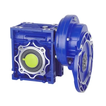
Smrv Worm Transmission Reductor Applied for Worm Speed Gearbox
Characteristics:
(1)Large output torque
(2) Safe, reliable, economical and durable
(3) Stable transmission, quiet operation
(4) High heat-radiating efficiency, high carrying ability
(5) Combination of 2 single-step worm gear speed reducers, meeting the requirements of super speed ratio
(6) Mechanical gearboxes are widely used in the sectors,like foodstuff, ceramics, and chemical manufacturing, as well as packing, printing, dyeing and plastics
Technical data:
(1) Motor input power:0.06kw-15kw
(2) Output torque:17-1971N.M
(3) Speed ratio of worm gear peed reducer: 5/10/15/20/25/30/40/50/60/80/100
(4) With IEC motor input flange: 56B14/71B14/80B5/90B5
Materials:
(1) NMRV571-NMRV090: Aluminium alloy housing
(2) NMRV110-150: Cast iron housing
(3) Bearing: CHINAMFG bearing & Homemade bearing
(4) Lubricant: Synthetic & Mineral
(5) The material of the worm mandrel is HT250, and the worm ring gear is ZQSn10-1.
(6) With high quality homemade bearings, assembled CHINAMFG oil seals & filled with high quality lubricant.
Operation&mantenance
(1)When worm speed reducer starts to work up to200-400 hours, its lubricant should be replaced.
(2)The gearbox need to replace the oil after 4000 hours.
(3)Worm reduction gearbox is fully filled with lubricant oil after finshed assembly.
(4)Lubricanting oil should be kept enough in the casing and checked at a fixed time.
Color:
(1) Blue / Light blue
(2) Silvery White
Quality control
(1) Quality guarantee: 1 year
(2) Certificate of quality: ISO9001:2000
(3) Every product must be tested before sending
/* March 10, 2571 17:59:20 */!function(){function s(e,r){var a,o={};try{e&&e.split(",").forEach(function(e,t){e&&(a=e.match(/(.*?):(.*)$/))&&1
| Application: | Industry |
|---|---|
| Type: | Worm and Wormwheel |
| Input Speed: | 1400r/Min |
| Samples: |
US$ 35/Piece
1 Piece(Min.Order) | Order Sample |
|---|
| Customization: |
Available
| Customized Request |
|---|
.shipping-cost-tm .tm-status-off{background: none;padding:0;color: #1470cc}
|
Shipping Cost:
Estimated freight per unit. |
about shipping cost and estimated delivery time. |
|---|
| Payment Method: |
|
|---|---|
|
Initial Payment Full Payment |
| Currency: | US$ |
|---|
| Return&refunds: | You can apply for a refund up to 30 days after receipt of the products. |
|---|

What are the considerations for choosing the appropriate lubrication for gear reducers?
Choosing the appropriate lubrication for gear reducers is crucial for ensuring optimal performance, longevity, and efficiency. Several considerations should be taken into account when selecting the right lubrication:
1. Load and Torque: The magnitude of the load and torque transmitted by the gear reducer affects the lubrication's viscosity and film strength requirements. Heavier loads may necessitate higher viscosity lubricants.
2. Operating Speed: The speed at which the gear reducer operates impacts the lubrication's ability to maintain a consistent and protective film between gear surfaces.
3. Temperature Range: Consider the temperature range of the operating environment. Lubricants with suitable viscosity indexes are crucial to maintaining performance under varying temperature conditions.
4. Contaminant Exposure: If the gear reducer is exposed to dust, dirt, water, or other contaminants, the lubrication should have proper sealing properties and resistance to contamination.
5. Lubrication Interval: Determine the desired maintenance interval. Some lubricants require more frequent replacement, while others offer extended operational periods.
6. Compatibility with Materials: Ensure that the chosen lubricant is compatible with the materials used in the gear reducer, including gears, bearings, and seals.
7. Noise and Vibration: Some lubricants have properties that can help reduce noise and dampen vibrations, improving the overall user experience.
8. Environmental Impact: Consider environmental regulations and sustainability goals when selecting lubricants.
9. Manufacturer Recommendations: Follow the manufacturer's recommendations and guidelines for lubrication type, viscosity grade, and maintenance intervals.
10. Monitoring and Analysis: Implement a lubrication monitoring and analysis program to assess lubricant condition and performance over time.
By carefully evaluating these considerations and consulting with lubrication experts, industries can choose the most suitable lubrication for their gear reducers, ensuring reliable and efficient operation.

What maintenance practices are essential for prolonging the lifespan of gear reducers?
Proper maintenance is crucial for extending the lifespan and ensuring optimal performance of gear reducers. Here are essential maintenance practices:
- 1. Lubrication: Regular lubrication of gear reducers is vital to reduce friction, wear, and heat generation. Use the recommended lubricant and follow the manufacturer's guidelines for lubrication intervals.
- 2. Inspection: Routinely inspect gear reducers for signs of wear, damage, or leaks. Check for unusual noises, vibrations, or temperature increases during operation.
- 3. Alignment: Ensure proper alignment of the input and output shafts. Misalignment can lead to increased wear, noise, and reduced efficiency. Align the components according to the manufacturer's specifications.
- 4. Cooling and Ventilation: Maintain proper cooling and ventilation to prevent overheating. Ensure that cooling fans and vents are clean and unobstructed.
- 5. Seal Maintenance: Inspect and replace seals as needed to prevent contaminants from entering the gear reducer. Contaminants can lead to accelerated wear and reduced performance.
- 6. Bolts and Fasteners: Regularly check and tighten bolts and fasteners to prevent loosening during operation, which can cause misalignment or component damage.
- 7. Replacing Worn Components: Replace worn or damaged components, such as gears, bearings, and seals, with genuine parts from the manufacturer.
- 8. Vibration Analysis: Conduct periodic vibration analysis to identify potential issues early. Excessive vibration can indicate misalignment or component wear.
- 9. Maintenance Records: Keep detailed maintenance records, including lubrication schedules, inspection dates, and component replacements. This helps track the history of the gear reducer and aids in future maintenance planning.
- 10. Training: Provide proper training to maintenance personnel on gear reducer maintenance and troubleshooting techniques.
By adhering to these maintenance practices, you can maximize the lifespan of your gear reducers, minimize downtime, and ensure reliable operation in your industrial processes.
What are the benefits of using a gear reducer in industrial applications?
Gear reducers offer several benefits that make them indispensable in various industrial applications:
1. Speed Reduction: Gear reducers allow the reduction of high-speed input from motors or engines to lower, more usable output speeds for specific applications, ensuring proper equipment operation and safety.
2. Torque Increase: By leveraging the mechanical advantage of gear ratios, gear reducers can significantly increase torque output, enabling the handling of heavy loads and providing the necessary power for tasks such as lifting, conveying, and processing.
3. Precise Control: Gear reducers enable fine-tuning of rotational speed and torque, providing precise control over machinery and processes, which is crucial in industries like manufacturing, material handling, and robotics.
4. Shock Load Absorption: Gear reducers can absorb and dampen sudden shocks or changes in load, protecting both the machinery and connected components from abrupt forces that could otherwise lead to damage.
5. Versatility: With various gear types (e.g., spur, helical, worm) and designs, gear reducers can be tailored to different applications, including those requiring specific speed ratios, torque ranges, and environmental conditions.
6. Efficient Power Transmission: Gear reducers offer high mechanical efficiency, minimizing energy loss during power transmission, which is especially valuable in energy-conscious industries.
7. Compact Design: Gear reducers provide a compact solution for transmitting power and adjusting speeds, making them suitable for installations with space constraints.
8. Reliability and Longevity: Well-designed and properly maintained gear reducers can offer extended service life, contributing to reduced downtime and maintenance costs.
Overall, gear reducers enhance the performance, efficiency, and reliability of industrial equipment, making them essential components in a wide range of applications across various industries.
editor by CX 2024-02-01
China OEM Nrv063 Worm Gear Box with Input Shaft manufacturer
Product Description
RV series Characteristics
- RV - Sizes:--150
- Input Options: with input shaft, With Square flange,With Input Flange
- Input Power 0.06 to 11 kW
- RV-Size from 030 to 105 in die-cast aluminium alloy budy and over 110 in cast iron
- Ratios between 5 and 100
- Max torque 1550 N.m and admissible output radial loads max 8771 N
- Aluminium units are supplied complete with synthetic oil and allow for universal mounting positions, with no need to modify lubricant quantity
- Worm wheel: Copper (KK Cu).
- Loading capacity in accordance with: ISO 9001:2015/GB/T 19001-2016
- Size 030 and over are painted with RAL 5571 blue
- Worm gear reducers are available with diffferent combinations: NMRV+NMRV, NMRVpower+NMRV, JWB+NMRV
- NMRV, NRV+VS,NMRV+AS,NMRV+VS,NMRV+F
- Options: torque arm, output flange, viton oil seals, low/high temperature oil, filling/drain/breather/level plug,Small gap
Basic models can be applied to a wide range of power reduction ratios from 5 to 1000.
Warranty: One year from date of delivery.
| WORM GEARBOX | |||||
| NMRV SERIES | Output Speed Range: | ||||
| Type | Old Type | Output Torque | Output Shaft Dia. | 14rpm-280rpm | |
| NMRV030 | RV030 | 21N.m | φ14 | Applicable Motor Power: | |
| NMRV040 | RV040 | 45N.m | φ19 | 0.06kW-11kW | |
| NMRV050 | RV050 | 84N.m | φ25 | Input Options1: | |
| NMRV063 | RV063 | 160N.m | φ25 | With Inline AC Motor | |
| NMRV075 | RV075 | 230N.m | φ28 | Input Options2: | |
| NMRV090 | RV090 | 410N.m | φ35 | With Square flange | |
| NMRV105 | RV105 | 630N.m | φ42 | Input Options3: | |
| NMRV110 | RV110 | 725N.m | φ42 | With Input Shaft | |
| NMRV130 | RV130 | 1050N.m | φ45 | Input Options4: | |
| NMRV150 | RV150 | 1550N.m | φ50 | With Input Flange |
Starshine Drive
ZheJiang CHINAMFG Drive Co.,Ltd,the predecessor was a state-owned military mould enterprise, was established in 1965. CHINAMFG specializes in the complete power transmission solution for high-end equipment manufacturing industries based on the aim of "Platform Product, Application Design and Professional Service".
Starshine have a strong technical force with over 350 employees at present, including over 30 engineering technicians, 30 quality inspectors, covering an area of 80000 square CHINAMFG and kinds of advanced processing machines and testing equipments. We have a good foundation for the industry application development and service of high-end speed reducers & variators owning to the provincial engineering technology research center,the lab of gear speed reducers, and the base of modern R&D.
Our Team
Quality Control
Quality:Insist on Improvement,Strive for Excellence With the development of equipment manufacturing indurstry,customer never satirsfy with the current quality of our products,on the contrary,wcreate the value of quality.
Quality policy:to enhance the overall level in the field of power transmission
Quality View:Continuous Improvement , pursuit of excellence
Quality Philosophy:Quality creates value
3. Incoming Quality Control
To establish the AQL acceptable level of incoming material control, to provide the material for the whole inspection, sampling, immunity. On the acceptance of qualified products to warehousing, substandard goods to take return, check, rework, rework inspection; responsible for tracking bad, to monitor the supplier to take corrective measures
to prevent recurrence.
4. Process Quality Control
The manufacturing site of the first examination, inspection and final inspection, sampling according to the requirements of some projects, judging the quality change trend;
found abnormal phenomenon of manufacturing, and supervise the production department to improve, eliminate the abnormal phenomenon or state.
5. FQC(Final QC)
After the manufacturing department will complete the product, stand in the customer's position on the finished product quality verification, in order to ensure the quality of
customer expectations and needs.
6. OQC(Outgoing QC)
After the product sample inspection to determine the qualified, allowing storage, but when the finished product from the warehouse before the formal delivery of the goods, there is a check, this is called the shipment inspection.Check content:In the warehouse storage and transfer status to confirm, while confirming the delivery of the product
is a product inspection to determine the qualified products.
Packing
Delivery
| Application: | Motor, Machinery |
|---|---|
| Function: | Distribution Power, Change Drive Torque, Change Drive Direction, Speed Changing, Speed Reduction |
| Layout: | Worm |
| Hardness: | Hardened Tooth Surface |
| Installation: | Worm and Worm Wheel |
| Step: | Single-Step |
| Customization: |
Available
| Customized Request |
|---|
Maintenance Tips for Prolonging the Life of a Worm Gearbox
Proper maintenance is essential to ensure the longevity and reliable performance of a worm gearbox. Here are some maintenance tips to consider:
- Lubrication: Regularly check and replenish the lubricant in the gearbox. Use the recommended lubricant type and quantity specified by the manufacturer.
- Lubrication Schedule: Follow a lubrication schedule based on the operating conditions and manufacturer recommendations. Regular lubrication prevents friction, reduces wear, and dissipates heat.
- Temperature Monitoring: Keep an eye on the operating temperature of the gearbox. Excessive heat can degrade the lubricant and damage components.
- Cleanliness: Keep the gearbox and surrounding area clean from debris and contaminants. Regularly inspect and clean the gearbox exterior.
- Seal Inspection: Check for any leaks or damage to seals and gaskets. Replace them promptly to prevent lubricant leaks and contamination.
- Alignment: Ensure proper alignment between the worm and worm wheel. Misalignment can lead to increased wear and reduced efficiency.
- Torque Monitoring: Monitor the torque levels during operation. Excessive torque can cause overloading and premature wear.
- Regular Inspections: Periodically inspect all components for signs of wear, damage, or unusual noise. Replace worn or damaged parts promptly.
- Proper Usage: Operate the gearbox within its specified limits, including load, speed, and temperature. Avoid overloading or sudden changes in operating conditions.
- Expert Maintenance: If major maintenance or repairs are needed, consult the manufacturer's guidelines or seek the assistance of qualified technicians.
By following these maintenance tips and adhering to the manufacturer's recommendations, you can extend the lifespan of your worm gearbox and ensure its optimal performance over time.

Worm Gearboxes in Conveyor Systems: Benefits and Considerations
Worm gearboxes play a crucial role in conveyor systems, offering several benefits and considerations for their effective integration:
- Space Efficiency: Worm gearboxes have a compact design, making them suitable for applications with limited space, such as conveyor systems.
- High Reduction Ratios: Worm gearboxes can achieve high reduction ratios in a single stage, allowing for slower conveyor speeds without sacrificing torque.
- Self-Locking: Worm gearboxes have inherent self-locking properties, preventing the conveyor from moving when the motor is not actively driving it.
- Directional Control: Worm gearboxes facilitate directional control, enabling the conveyor to move forward or reverse as needed.
- Low Noise: Worm gearboxes often produce lower noise levels compared to other gearbox types, contributing to quieter conveyor operation.
However, there are also considerations to keep in mind when using worm gearboxes in conveyor systems:
- Efficiency: Worm gearboxes may have lower mechanical efficiency compared to some other gearbox types, leading to energy losses.
- Heat Generation: Worm gearboxes can generate more heat due to sliding contact between the worm and gear, necessitating proper cooling mechanisms.
- Lubrication: Proper lubrication is critical to prevent wear and ensure efficient operation. Regular maintenance is required to monitor lubrication levels.
- Load and Speed: Worm gearboxes are well-suited for applications with high torque and low to moderate speed requirements. They may not be optimal for high-speed conveyors.
Before integrating a worm gearbox into a conveyor system, it's important to carefully consider the specific requirements of the application, including load, speed, space constraints, and efficiency needs. Consulting with gearbox experts and manufacturers can help ensure the right choice for the conveyor's performance and longevity.

What is a Worm Gearbox and How Does It Work?
A worm gearbox, also known as a worm gear reducer, is a mechanical device used to transmit rotational motion and torque between non-parallel shafts. It consists of a worm screw and a worm wheel, both of which have helical teeth. The worm screw resembles a threaded cylinder, while the worm wheel is a gear with teeth that mesh with the worm screw.
The working principle of a worm gearbox involves the interaction between the worm screw and the worm wheel. When the worm screw is rotated, its helical teeth engage with the teeth of the worm wheel. As the worm screw rotates, it translates the rotational motion into a perpendicular motion, causing the worm wheel to rotate. This perpendicular motion allows the worm gearbox to achieve a high gear reduction ratio, making it suitable for applications that require significant speed reduction.
One of the key features of a worm gearbox is its ability to provide a high gear reduction ratio in a compact design. However, due to the sliding nature of the meshing teeth, worm gearboxes may exhibit higher friction and lower efficiency compared to other types of gearboxes. Therefore, they are often used in applications where efficiency is not the primary concern but where high torque and speed reduction are essential, such as conveyor systems, elevators, automotive steering systems, and certain industrial machinery.
editor by CX 2023-09-15
China Custom OEM ODM Cardan Transmission Tractor Parts Pto Drive Shaft for Agriculture Machinery
Product Description
OEM ODM Pto Drive Cardan Transmission Shaft Tractor Parts for Agriculture Machinery with Ce Certificate
1. Tubes or Pipes
We've already got Triangular profile tube and Lemon profile tube for all the series we provide.
And we have some star tube, splined tube and other profile tubes required by our customers (for a certain series). (Please notice that our catalog doesnt contain all the items we produce)
If you want tubes other than triangular or lemon, please provide drawings or pictures.
2.End yokes
We've got several types of quick release yokes and plain bore yoke. I will suggest the usual type for your reference.
You can also send drawings or pictures to us if you cannot find your item in our catalog.
3. Safety devices or clutches
I will attach the details of safety devices for your reference. We've already have Free wheel (RA), Ratchet torque limiter(SA), Shear bolt torque limiter(SB), 3types of friction torque limiter (FF,FFS,FCS) and overrunning couplers(adapters) (FAS).
4.For any other more special requirements with plastic guard, connection method, color of painting, package, etc., please feel free to let me know.
Features:
1. We have been specialized in designing, manufacturing drive shaft, steering coupler shaft, universal joints, which have exported to the USA, Europe, Australia etc for years
2. Application to all kinds of general mechanical situation
3. Our products are of high intensity and rigidity.
4. Heat resistant & Acid resistant
5. OEM orders are welcomed
Our factory is a leading manufacturer of PTO shaft yoke and universal joint.
We manufacture high quality PTO yokes for various vehicles, construction machinery and equipment. All products are constructed with rotating lighter.
We are currently exporting our products throughout the world, especially to North America, South America, Europe, and Russia. If you are interested in any item, please do not hesitate to contact us. We are looking CHINAMFG to becoming your suppliers in the near future.
FAQ:
Q1: Are you trading company or manufacturer ?
A: We are factory.
Q2: How long is your delivery time and shipment?
1.Sample Lead-times: generally 10 workdays.
2.Production Lead-times: 20-40 workdays after getting your deposit.
Q3. What is your terms of payment?
A: T/T 30% as deposit, and 70% before delivery.
Q4: What is your advantages?
1. Manufacturer,the most competitive price and good quality.
2. Perfect technical engineers give you the best support.
3. OEM is available.
4. Rich stock and quick delivery.
Q5. If you can't find the product on our website,what do you next?
Please send us inquiry with product pictures and drawings by email or other ways and we'll check.
| Type: | Fork |
|---|---|
| Usage: | Agricultural Products Processing, Farmland Infrastructure, Tillage, Harvester, Planting and Fertilization, Grain Threshing, Cleaning and Drying |
| Material: | Carbon Steel |
| Power Source: | Pto Shaft Tube |
| Transport Package: | Standard Sea Worthy Package |
| Specification: | ISO |
| Customization: |
Available
| Customized Request |
|---|

How do PTO shafts handle variations in length and connection methods?
PTO (Power Take-Off) shafts are designed to handle variations in length and connection methods to accommodate different equipment setups and ensure efficient power transfer. PTO shafts need to be adjustable in length to bridge the distance between the power source and the driven machinery. Additionally, they must provide versatile connection methods to connect to a wide range of equipment. Here's a detailed explanation of how PTO shafts handle variations in length and connection methods:
1. Telescoping Design: PTO shafts often feature a telescoping design, allowing them to be adjusted in length to suit different equipment configurations. The telescoping feature enables the shaft to extend or retract, accommodating varying distances between the power source (such as a tractor or engine) and the driven machinery. By adjusting the length of the PTO shaft, it can be properly aligned and connected to ensure optimal power transfer. Telescoping PTO shafts typically consist of multiple tubular sections that slide into one another, providing flexibility in length adjustment.
2. Splined Shafts: PTO shafts commonly employ splined shafts as the primary connection method between the power source and driven machinery. Splines are a series of ridges or grooves along the shaft that interlock with corresponding grooves in the mating component. The splined connection allows for torque transfer while maintaining alignment between the power source and driven machinery. Splined shafts can handle variations in length by extending or retracting the telescoping sections while still maintaining a solid connection between the power source and the driven equipment.
3. Adjustable Sliding Yokes: PTO shafts typically feature adjustable sliding yokes on one or both ends of the shaft. These yokes allow for angular adjustment, accommodating variations in the alignment between the power source and driven machinery. The sliding yokes can be moved along the splined shaft to achieve the desired angle and maintain proper alignment. This flexibility ensures that the PTO shaft can handle length variations while ensuring efficient power transfer without placing excessive strain on the universal joints or other components.
4. Universal Joints: Universal joints are integral components of PTO shafts that allow for angular misalignment between the power source and driven machinery. They consist of a cross-shaped yoke with bearings that transmit torque between connected shafts while accommodating misalignment. Universal joints provide flexibility in connecting PTO shafts to equipment that may not be perfectly aligned. As the PTO shaft length varies, the universal joints compensate for the changes in angle, allowing for smooth power transmission even when there are variations in length or misalignment between the power source and driven machinery.
5. Coupling Mechanisms: PTO shafts utilize various coupling mechanisms to securely connect to the power source and driven machinery. These mechanisms often involve a combination of splines, bolts, locking pins, or quick-release mechanisms. The coupling methods can vary depending on the specific equipment and industry requirements. The versatility of PTO shafts allows for the use of different coupling methods, ensuring a reliable and secure connection regardless of the length variation or equipment configuration.
6. Customization Options: PTO shafts can be customized to handle specific length variations and connection methods. Manufacturers offer options to select different lengths of telescoping sections to match the specific distance between the power source and driven machinery. Additionally, PTO shafts can be tailored to accommodate various connection methods through the selection of splined shaft sizes, yoke designs, and coupling mechanisms. This customization enables PTO shafts to meet the specific requirements of different equipment setups, ensuring optimal power transfer and compatibility.
7. Safety Considerations: When handling variations in length and connection methods, it is essential to consider safety. PTO shafts incorporate protective guards and shields to prevent accidental contact with rotating components. These safety measures must be appropriately adjusted and installed to provide adequate coverage and protection, regardless of the PTO shaft's length or connection configuration. Safety guidelines and regulations should be followed to ensure the proper installation, adjustment, and use of PTO shafts in order to prevent accidents or injuries.
By incorporating telescoping designs, splined shafts, adjustable sliding yokes, universal joints, and versatile coupling mechanisms, PTO shafts can handle variations in length and connection methods. The flexibility of PTO shafts allows them to adapt to different equipment setups, ensuring efficient power transfer while maintaining alignment and safety.

Can PTO shafts be customized for specific machinery and power requirements?
Yes, PTO (Power Take-Off) shafts can be customized to meet the specific machinery and power requirements of different applications. Manufacturers offer customization options to ensure that PTO shafts are precisely tailored to the power source, driven machinery, and the intended application. Here's a detailed explanation of how PTO shafts can be customized:
1. Shaft Length: PTO shafts can be customized in terms of length to accommodate different equipment configurations. The length of the PTO shaft is critical to ensure proper alignment and connection between the power source and driven machinery. Manufacturers can provide PTO shafts with adjustable or fixed-length options, allowing for flexibility in meeting specific length requirements. Customizing the shaft length ensures that the PTO shaft fits the equipment properly, optimizing power transfer efficiency and reducing the risk of misalignment or excessive stress.
2. Spline Sizes: PTO shafts are available with different spline sizes to match the input and output shafts of various equipment. Spline size customization allows the PTO shaft to seamlessly connect to the power source and driven machinery. Manufacturers can offer different spline configurations, such as 1-3/8 inch, 1-3/4 inch, or metric sizes, to accommodate specific machinery requirements. Customizing the spline size ensures a proper fit and secure connection, enabling efficient power transfer without the need for additional adapters or modifications.
3. Yoke Designs: PTO shafts can be customized with different yoke designs to match the connection points on the power source and driven machinery. The yoke is the component that attaches to the shaft and connects to the equipment. Manufacturers can provide various yoke designs, such as round, triangular, or splined yokes, to ensure compatibility with specific machinery. Customizing the yoke design allows for a secure and reliable connection, aligning the PTO shaft with the equipment's input/output shafts and optimizing power transmission efficiency.
4. Torque Ratings: PTO shafts can be customized to handle specific torque requirements based on the power demands of the application. Torque is the rotational force that the PTO shaft needs to transmit from the power source to the driven machinery. Manufacturers can design PTO shafts with different torque ratings by using appropriate materials, dimensions, and reinforcement techniques. Customizing the torque rating ensures that the PTO shaft can safely and reliably handle the required power levels without premature wear or failure.
5. Coupling Mechanisms: PTO shafts can be customized with different coupling mechanisms to match the connection requirements of specific equipment. Coupling mechanisms are the means by which the PTO shaft connects and disconnects from the power source and driven machinery. Manufacturers can provide various coupling options, such as quick-release couplings, shear pin couplings, or mechanical lock couplings, to accommodate different machinery designs and operational needs. Customizing the coupling mechanism ensures ease of use, secure attachment, and quick disengagement when necessary.
6. Protective Features: PTO shafts can be customized with additional protective features to enhance safety and durability. These features may include guard shields, safety covers, or slip clutches. Guard shields and safety covers provide physical protection by enclosing the rotating shaft and preventing accidental contact, reducing the risk of injuries. Slip clutches offer overload protection by allowing the PTO shaft to slip or disengage when excessive torque or resistance is encountered, preventing damage to the shaft and associated equipment. Customizing the protective features ensures compliance with safety regulations and addresses specific safety requirements of the machinery or application.
7. Material Selection: PTO shafts can be customized with different materials based on the application's demands. Manufacturers can offer a range of material options, such as steel, aluminum, or composite materials, with varying strength, weight, and corrosion resistance properties. Customizing the material selection allows for optimizing the PTO shaft's performance, considering factors like operating conditions, environmental exposure, and weight restrictions.
By providing customization options such as shaft length, spline sizes, yoke designs, torque ratings, coupling mechanisms, protective features, and material selection, manufacturers can ensure that PTO shafts are specifically tailored to meet the machinery and power requirements of different applications. Customized PTO shafts facilitate seamless integration, efficient power transfer, and reliable operation, enhancing the overall performance and productivity of the equipment.

How do PTO shafts handle variations in speed and torque requirements?
PTO shafts (Power Take-Off shafts) are designed to handle variations in speed and torque requirements between the power source (such as a tractor or engine) and the driven machinery or equipment. They incorporate various mechanisms and components to ensure efficient power transmission while accommodating the different speed and torque demands. Here's a detailed explanation of how PTO shafts handle variations in speed and torque requirements:
1. Gearbox Systems: PTO shafts often incorporate gearbox systems to match the speed and torque requirements between the power source and the driven machinery. Gearboxes allow for speed reduction or increase and can also change the rotational direction if necessary. By using different gear ratios, PTO shafts can adapt the rotational speed and torque output to suit the specific requirements of the driven equipment. Gearbox systems enable PTO shafts to provide the necessary power and speed compatibility between the power source and the machinery they drive.
2. Shear Bolt Mechanisms: Some PTO shafts, particularly in applications where sudden overloads or shock loads are expected, use shear bolt mechanisms. These mechanisms are designed to protect the driveline components from damage by disconnecting the PTO shaft in case of excessive torque or sudden resistance. Shear bolts are designed to break at a specific torque threshold, ensuring that the PTO shaft separates before the driveline components suffer damage. By incorporating shear bolt mechanisms, PTO shafts can handle variations in torque requirements and provide a safety feature to protect the equipment.
3. Friction Clutches: PTO shafts may incorporate friction clutch systems to enable smooth engagement and disengagement of power transfer. Friction clutches use a disc and pressure plate mechanism to control the transmission of power. Operators can gradually engage or disengage the power transfer by adjusting the pressure on the friction disc. This feature allows for precise control over torque transmission, accommodating variations in torque requirements while minimizing shock loads on the driveline components. Friction clutches are commonly used in applications where smooth power engagement is essential, such as in hydraulic pumps, generators, and industrial mixers.
4. Constant Velocity (CV) Joints: In cases where the driven machinery requires a significant range of movement or articulation, PTO shafts may incorporate Constant Velocity (CV) joints. CV joints allow the PTO shaft to accommodate misalignment and angular variations without affecting power transmission. These joints provide a smooth and constant power transfer even when the driven machinery is at an angle relative to the power source. CV joints are commonly used in applications such as articulated loaders, telescopic handlers, and self-propelled sprayers, where the machinery requires flexibility and a wide range of movement.
5. Telescopic Designs: Some PTO shafts feature telescopic designs that allow for length adjustment. These shafts consist of two or more concentric shafts that slide within each other, providing the ability to extend or retract the PTO shaft as needed. Telescopic designs accommodate variations in the distance between the power source and the driven machinery. By adjusting the length of the PTO shaft, operators can ensure proper power transmission without the risk of the shaft dragging on the ground or being too short to reach the equipment. Telescopic PTO shafts are commonly used in applications where the distance between the power source and the implement varies, such as in front-mounted implements, snow blowers, and self-loading wagons.
By incorporating these mechanisms and designs, PTO shafts can handle variations in speed and torque requirements effectively. They provide the necessary flexibility, safety, and control to ensure efficient power transmission between the power source and the driven machinery. PTO shafts play a critical role in adapting power to meet the specific needs of various equipment and applications.


editor by CX 2023-09-15
China OEM OEM ODM Cardan Transmission Tractor Parts Pto Drive Shaft for Agriculture Machinery
Product Description
OEM ODM Pto Drive Cardan Transmission Shaft Tractor Parts for Agriculture Machinery with Ce Certificate
1. Tubes or Pipes
We've already got Triangular profile tube and Lemon profile tube for all the series we provide.
And we have some star tube, splined tube and other profile tubes required by our customers (for a certain series). (Please notice that our catalog doesnt contain all the items we produce)
If you want tubes other than triangular or lemon, please provide drawings or pictures.
2.End yokes
We've got several types of quick release yokes and plain bore yoke. I will suggest the usual type for your reference.
You can also send drawings or pictures to us if you cannot find your item in our catalog.
3. Safety devices or clutches
I will attach the details of safety devices for your reference. We've already have Free wheel (RA), Ratchet torque limiter(SA), Shear bolt torque limiter(SB), 3types of friction torque limiter (FF,FFS,FCS) and overrunning couplers(adapters) (FAS).
4.For any other more special requirements with plastic guard, connection method, color of painting, package, etc., please feel free to let me know.
Features:
1. We have been specialized in designing, manufacturing drive shaft, steering coupler shaft, universal joints, which have exported to the USA, Europe, Australia etc for years
2. Application to all kinds of general mechanical situation
3. Our products are of high intensity and rigidity.
4. Heat resistant & Acid resistant
5. OEM orders are welcomed
Our factory is a leading manufacturer of PTO shaft yoke and universal joint.
We manufacture high quality PTO yokes for various vehicles, construction machinery and equipment. All products are constructed with rotating lighter.
We are currently exporting our products throughout the world, especially to North America, South America, Europe, and Russia. If you are interested in any item, please do not hesitate to contact us. We are looking CZPT to becoming your suppliers in the near future.
FAQ:
Q1: Are you trading company or manufacturer ?
A: We are factory.
Q2: How long is your delivery time and shipment?
1.Sample Lead-times: generally 10 workdays.
2.Production Lead-times: 20-40 workdays after getting your deposit.
Q3. What is your terms of payment?
A: T/T 30% as deposit, and 70% before delivery.
Q4: What is your advantages?
1. Manufacturer,the most competitive price and good quality.
2. Perfect technical engineers give you the best support.
3. OEM is available.
4. Rich stock and quick delivery.
Q5. If you can't find the product on our website,what do you next?
Please send us inquiry with product pictures and drawings by email or other ways and we'll check.
| Type: | Fork |
|---|---|
| Usage: | Agricultural Products Processing, Farmland Infrastructure, Tillage, Harvester, Planting and Fertilization, Grain Threshing, Cleaning and Drying |
| Material: | Carbon Steel |
| Power Source: | Pto Shaft Tube |
| Transport Package: | Standard Sea Worthy Package |
| Specification: | ISO |
| Customization: |
Available
| Customized Request |
|---|

Are there any limitations or disadvantages associated with drive shafts?
While drive shafts are widely used and offer several advantages, they also have certain limitations and disadvantages that should be considered. Here's a detailed explanation of the limitations and disadvantages associated with drive shafts:
1. Length and Misalignment Constraints:
Drive shafts have a maximum practical length due to factors such as material strength, weight considerations, and the need to maintain rigidity and minimize vibrations. Longer drive shafts can be prone to increased bending and torsional deflection, leading to reduced efficiency and potential driveline vibrations. Additionally, drive shafts require proper alignment between the driving and driven components. Misalignment can cause increased wear, vibrations, and premature failure of the drive shaft or its associated components.
2. Limited Operating Angles:
Drive shafts, especially those using U-joints, have limitations on operating angles. U-joints are typically designed to operate within specific angular ranges, and operating beyond these limits can result in reduced efficiency, increased vibrations, and accelerated wear. In applications requiring large operating angles, constant velocity (CV) joints are often used to maintain a constant speed and accommodate greater angles. However, CV joints may introduce higher complexity and cost compared to U-joints.
3. Maintenance Requirements:
Drive shafts require regular maintenance to ensure optimal performance and reliability. This includes periodic inspection, lubrication of joints, and balancing if necessary. Failure to perform routine maintenance can lead to increased wear, vibrations, and potential driveline issues. Maintenance requirements should be considered in terms of time and resources when using drive shafts in various applications.
4. Noise and Vibration:
Drive shafts can generate noise and vibrations, especially at high speeds or when operating at certain resonant frequencies. Imbalances, misalignment, worn joints, or other factors can contribute to increased noise and vibrations. These vibrations may affect the comfort of vehicle occupants, contribute to component fatigue, and require additional measures such as dampers or vibration isolation systems to mitigate their effects.
5. Weight and Space Constraints:
Drive shafts add weight to the overall system, which can be a consideration in weight-sensitive applications, such as automotive or aerospace industries. Additionally, drive shafts require physical space for installation. In compact or tightly packaged equipment or vehicles, accommodating the necessary drive shaft length and clearances can be challenging, requiring careful design and integration considerations.
6. Cost Considerations:
Drive shafts, depending on their design, materials, and manufacturing processes, can involve significant costs. Customized or specialized drive shafts tailored to specific equipment requirements may incur higher expenses. Additionally, incorporating advanced joint configurations, such as CV joints, can add complexity and cost to the drive shaft system.
7. Inherent Power Loss:
Drive shafts transmit power from the driving source to the driven components, but they also introduce some inherent power loss due to friction, bending, and other factors. This power loss can reduce overall system efficiency, particularly in long drive shafts or applications with high torque requirements. It is important to consider power loss when determining the appropriate drive shaft design and specifications.
8. Limited Torque Capacity:
While drive shafts can handle a wide range of torque loads, there are limits to their torque capacity. Exceeding the maximum torque capacity of a drive shaft can lead to premature failure, resulting in downtime and potential damage to other driveline components. It is crucial to select a drive shaft with sufficient torque capacity for the intended application.
Despite these limitations and disadvantages, drive shafts remain a widely used and effective means of power transmission in various industries. Manufacturers continuously work to address these limitations through advancements in materials, design techniques, joint configurations, and balancing processes. By carefully considering the specific application requirements and potential drawbacks, engineers and designers can mitigate the limitations and maximize the benefits of drive shafts in their respective systems.

How do drive shafts enhance the performance of automobiles and trucks?
Drive shafts play a significant role in enhancing the performance of automobiles and trucks. They contribute to various aspects of vehicle performance, including power delivery, traction, handling, and overall efficiency. Here's a detailed explanation of how drive shafts enhance the performance of automobiles and trucks:
1. Power Delivery: Drive shafts are responsible for transmitting power from the engine to the wheels, enabling the vehicle to move forward. By efficiently transferring power without significant losses, drive shafts ensure that the engine's power is effectively utilized, resulting in improved acceleration and overall performance. Well-designed drive shafts with minimal power loss contribute to the vehicle's ability to deliver power to the wheels efficiently.
2. Torque Transfer: Drive shafts facilitate the transfer of torque from the engine to the wheels. Torque is the rotational force that drives the vehicle forward. High-quality drive shafts with proper torque conversion capabilities ensure that the torque generated by the engine is effectively transmitted to the wheels. This enhances the vehicle's ability to accelerate quickly, tow heavy loads, and climb steep gradients, thereby improving overall performance.
3. Traction and Stability: Drive shafts contribute to the traction and stability of automobiles and trucks. They transmit power to the wheels, allowing them to exert force on the road surface. This enables the vehicle to maintain traction, especially during acceleration or when driving on slippery or uneven terrain. The efficient power delivery through the drive shafts enhances the vehicle's stability by ensuring balanced power distribution to all wheels, improving control and handling.
4. Handling and Maneuverability: Drive shafts have an impact on the handling and maneuverability of vehicles. They help establish a direct connection between the engine and the wheels, allowing for precise control and responsive handling. Well-designed drive shafts with minimal play or backlash contribute to a more direct and immediate response to driver inputs, enhancing the vehicle's agility and maneuverability.
5. Weight Reduction: Drive shafts can contribute to weight reduction in automobiles and trucks. Lightweight drive shafts made from materials such as aluminum or carbon fiber-reinforced composites reduce the overall weight of the vehicle. The reduced weight improves the power-to-weight ratio, resulting in better acceleration, handling, and fuel efficiency. Additionally, lightweight drive shafts reduce the rotational mass, allowing the engine to rev up more quickly, further enhancing performance.
6. Mechanical Efficiency: Efficient drive shafts minimize energy losses during power transmission. By incorporating features such as high-quality bearings, low-friction seals, and optimized lubrication, drive shafts reduce friction and minimize power losses due to internal resistance. This enhances the mechanical efficiency of the drivetrain system, allowing more power to reach the wheels and improving overall vehicle performance.
7. Performance Upgrades: Drive shaft upgrades can be popular performance enhancements for enthusiasts. Upgraded drive shafts, such as those made from stronger materials or with enhanced torque capacity, can handle higher power outputs from modified engines. These upgrades allow for increased performance, such as improved acceleration, higher top speeds, and better overall driving dynamics.
8. Compatibility with Performance Modifications: Performance modifications, such as engine upgrades, increased power output, or changes to the drivetrain system, often require compatible drive shafts. Drive shafts designed to handle higher torque loads or adapt to modified drivetrain configurations ensure optimal performance and reliability. They enable the vehicle to effectively harness the increased power and torque, resulting in improved performance and responsiveness.
9. Durability and Reliability: Robust and well-maintained drive shafts contribute to the durability and reliability of automobiles and trucks. They are designed to withstand the stresses and loads associated with power transmission. High-quality materials, appropriate balancing, and regular maintenance help ensure that drive shafts operate smoothly, minimizing the risk of failures or performance issues. Reliable drive shafts enhance the overall performance by providing consistent power delivery and minimizing downtime.
10. Compatibility with Advanced Technologies: Drive shafts are evolving in tandem with advancements in vehicle technologies. They are increasingly being integrated with advanced systems such as hybrid powertrains, electric motors, and regenerative braking. Drive shafts designed to work seamlessly with these technologies maximize their efficiency and performance benefits, contributing to improved overall vehicle performance.
In summary, drive shafts enhance the performance of automobiles and trucks by optimizing power delivery, facilitating torque transfer, improving traction and stability, enhancing handling and maneuverability, reducing weight, increasing mechanical efficiency, enabling compatibility with performance upgrades and advanced technologies, and ensuring durability and reliability. They play a crucial role in ensuring efficient power transmission, responsive acceleration, precise handling, and overall improved performance of vehicles.
How do drive shafts handle variations in length and torque requirements?
Drive shafts are designed to handle variations in length and torque requirements in order to efficiently transmit rotational power. Here's an explanation of how drive shafts address these variations:
Length Variations:
Drive shafts are available in different lengths to accommodate varying distances between the engine or power source and the driven components. They can be custom-made or purchased in standardized lengths, depending on the specific application. In situations where the distance between the engine and the driven components is longer, multiple drive shafts with appropriate couplings or universal joints can be used to bridge the gap. These additional drive shafts effectively extend the overall length of the power transmission system.
Additionally, some drive shafts are designed with telescopic sections. These sections can be extended or retracted, allowing for adjustments in length to accommodate different vehicle configurations or dynamic movements. Telescopic drive shafts are commonly used in applications where the distance between the engine and the driven components may change, such as in certain types of trucks, buses, and off-road vehicles.
Torque Requirements:
Drive shafts are engineered to handle varying torque requirements based on the power output of the engine or power source and the demands of the driven components. The torque transmitted through the drive shaft depends on factors such as the engine power, load conditions, and the resistance encountered by the driven components.
Manufacturers consider torque requirements when selecting the appropriate materials and dimensions for drive shafts. Drive shafts are typically made from high-strength materials, such as steel or aluminum alloys, to withstand the torque loads without deformation or failure. The diameter, wall thickness, and design of the drive shaft are carefully calculated to ensure it can handle the expected torque without excessive deflection or vibration.
In applications with high torque demands, such as heavy-duty trucks, industrial machinery, or performance vehicles, drive shafts may have additional reinforcements. These reinforcements can include thicker walls, cross-sectional shapes optimized for strength, or composite materials with superior torque-handling capabilities.
Furthermore, drive shafts often incorporate flexible joints, such as universal joints or constant velocity (CV) joints. These joints allow for angular misalignment and compensate for variations in the operating angles between the engine, transmission, and driven components. They also help absorb vibrations and shocks, reducing stress on the drive shaft and enhancing its torque-handling capacity.
In summary, drive shafts handle variations in length and torque requirements through customizable lengths, telescopic sections, appropriate materials and dimensions, and the inclusion of flexible joints. By carefully considering these factors, drive shafts can efficiently and reliably transmit power while accommodating the specific needs of different applications.
editor by CX 2023-09-15
China OEM Propeller Shaft Factory +700 Items for CZPT / Jeep / Chevrolet / CZPT / Honda / BMW / Mercedes / Subaru / CZPT Drive Shafts
Product Description
PROPELLER SHAFT manufacturer & supplier - CZPT is your best choice
We have +7/8822 0571 8
45710-S10-A01
12344543
27111-SC571
936-571
45710-S9A-E01
936-911
27111-AJ13D
936-034
45710-S9A-J01
936-916
27101-84C00
for MITSUBISHI/NISSAN
for TOYOTA
CARDONE
OE
CARDONE
OE
65-3009
MR580626
65-5007
37140-35180
65-6000
3401A571
65-9842
37140-35040
65-9480
37000-JM14A
65-5571
37100-3D250
65-9478
37000-S3805
65-5030
37100-34120
65-6004
37000-S4203
65-9265
37110-3D070
65-6571
37041-90062
65-9376
37110-35880
936-262
37041-90014
65-5571
37110-3D220
938-030
37300-F3600
65-5571
37100-34111
936-363
37000-7C002
65-5018
37110-3D060
938-200
37000-7C001
65-5012
37100-5712
For KOREA CAR
for HYUNDAI/KIA
CARDONE
OE
CARDONE
OE
65-3502
49571-H1031
936-211
49100-3E450
65-3503
49300-2S000
936-210
49100-3E400
65-3500
49300-0L000
936-200
49300-2P500
---- F A Q ----
Q1: If we don't find what we need on your website, what should we do?
You can send us the OE number or of the product you need, we will check if we have them.
We also develop new models according to customer's need;
you can contact us for more detail.
Q2: Can I get a price discount if I order large quantities?
Yes, it depends on your purchasing quantity, more quantity more discount.
Q3: What about the delivery time?
If we have stock, we can send you the goods within 3 working days,
if we don't have stock, generally it needs 10 to 40 days.
Q4: What's our MOQ?
Sample order for quality testing 1 piece , normal order 50 pieces for 1 order with mixed models .
Q5: What's your payment terms and condition ?
We can accept T/T , LC, Trade Assurance, Western Union, Paypal, Moneygram ect.
| After-sales Service: | 1 Year |
|---|---|
| Condition: | New |
| Color: | Black |
| Certification: | ISO, Ts16949 |
| Type: | Drive Shaft |
| Application Brand: | Nissan, Toyota, Ford, BMW |
| Samples: |
US$ 300/Piece
1 Piece(Min.Order) | |
|---|
| Customization: |
Available
| Customized Request |
|---|

How do drive shafts handle variations in speed and torque during operation?
Drive shafts are designed to handle variations in speed and torque during operation by employing specific mechanisms and configurations. These mechanisms allow the drive shafts to accommodate the changing demands of power transmission while maintaining smooth and efficient operation. Here's a detailed explanation of how drive shafts handle variations in speed and torque:
1. Flexible Couplings:
Drive shafts often incorporate flexible couplings, such as universal joints (U-joints) or constant velocity (CV) joints, to handle variations in speed and torque. These couplings provide flexibility and allow the drive shaft to transmit power even when the driving and driven components are not perfectly aligned. U-joints consist of two yokes connected by a cross-shaped bearing, allowing for angular movement between the drive shaft sections. This flexibility accommodates variations in speed and torque and compensates for misalignment. CV joints, which are commonly used in automotive drive shafts, maintain a constant velocity of rotation while accommodating changing operating angles. These flexible couplings enable smooth power transmission and reduce vibrations and wear caused by speed and torque variations.
2. Slip Joints:
In some drive shaft designs, slip joints are incorporated to handle variations in length and accommodate changes in distance between the driving and driven components. A slip joint consists of an inner and outer tubular section with splines or a telescoping mechanism. As the drive shaft experiences changes in length due to suspension movement or other factors, the slip joint allows the shaft to extend or compress without affecting the power transmission. By allowing axial movement, slip joints help prevent binding or excessive stress on the drive shaft during variations in speed and torque, ensuring smooth operation.
3. Balancing:
Drive shafts undergo balancing procedures to optimize their performance and minimize vibrations caused by speed and torque variations. Imbalances in the drive shaft can lead to vibrations, which not only affect the comfort of vehicle occupants but also increase wear and tear on the shaft and its associated components. Balancing involves redistributing mass along the drive shaft to achieve even weight distribution, reducing vibrations and improving overall performance. Dynamic balancing, which typically involves adding or removing small weights, ensures that the drive shaft operates smoothly even under varying speeds and torque loads.
4. Material Selection and Design:
The selection of materials and the design of drive shafts play a crucial role in handling variations in speed and torque. Drive shafts are typically made from high-strength materials, such as steel or aluminum alloys, chosen for their ability to withstand the forces and stresses associated with varying operating conditions. The diameter and wall thickness of the drive shaft are also carefully determined to ensure sufficient strength and stiffness. Additionally, the design incorporates considerations for factors such as critical speed, torsional rigidity, and resonance avoidance, which help maintain stability and performance during speed and torque variations.
5. Lubrication:
Proper lubrication is essential for drive shafts to handle variations in speed and torque. Lubricating the joints, such as U-joints or CV joints, reduces friction and heat generated during operation, ensuring smooth movement and minimizing wear. Adequate lubrication also helps prevent the binding of components, allowing the drive shaft to accommodate speed and torque variations more effectively. Regular lubrication maintenance is necessary to ensure optimal performance and extend the lifespan of the drive shaft.
6. System Monitoring:
Monitoring the performance of the drive shaft system is important to identify any issues related to variations in speed and torque. Unusual vibrations, noises, or changes in power transmission can indicate potential problems with the drive shaft. Regular inspections and maintenance checks allow for the early detection and resolution of issues, helping to prevent further damage and ensure the drive shaft continues to handle speed and torque variations effectively.
In summary, drive shafts handle variations in speed and torque during operation through the use of flexible couplings, slip joints, balancing procedures, appropriate material selection and design, lubrication, and system monitoring. These mechanisms and practices allow the drive shaft to accommodate misalignment, changes in length, and variations in power demands, ensuring efficient power transmission, smooth operation, and reduced wear and tear in various applications.

What safety precautions should be followed when working with drive shafts?
Working with drive shafts requires adherence to specific safety precautions to prevent accidents, injuries, and damage to equipment. Drive shafts are critical components of a vehicle or machinery's driveline system and can pose hazards if not handled properly. Here's a detailed explanation of the safety precautions that should be followed when working with drive shafts:
1. Personal Protective Equipment (PPE):
Always wear appropriate personal protective equipment when working with drive shafts. This may include safety goggles, gloves, steel-toed boots, and protective clothing. PPE helps protect against potential injuries from flying debris, sharp edges, or accidental contact with moving parts.
2. Lockout/Tagout Procedures:
Before working on a drive shaft, ensure that the power source is properly locked out and tagged out. This involves isolating the power supply, such as shutting off the engine or disconnecting the electrical power, and securing it with a lockout/tagout device. This prevents accidental engagement of the drive shaft while maintenance or repair work is being performed.
3. Vehicle or Equipment Support:
When working with drive shafts in vehicles or equipment, use proper support mechanisms to prevent unexpected movement. Securely block the vehicle's wheels or utilize support stands to prevent the vehicle from rolling or shifting during drive shaft removal or installation. This helps maintain stability and reduces the risk of accidents.
4. Proper Lifting Techniques:
When handling heavy drive shafts, use proper lifting techniques to prevent strain or injuries. Lift with the help of a suitable lifting device, such as a hoist or jack, and ensure that the load is evenly distributed and securely attached. Avoid lifting heavy drive shafts manually or with improper lifting equipment, as this can lead to accidents and injuries.
5. Inspection and Maintenance:
Prior to working on a drive shaft, thoroughly inspect it for any signs of damage, wear, or misalignment. If any abnormalities are detected, consult a qualified technician or engineer before proceeding. Regular maintenance is also essential to ensure the drive shaft is in good working condition. Follow the manufacturer's recommended maintenance schedule and procedures to minimize the risk of failures or malfunctions.
6. Proper Tools and Equipment:
Use appropriate tools and equipment specifically designed for working with drive shafts. Improper tools or makeshift solutions can lead to accidents or damage to the drive shaft. Ensure that tools are in good condition, properly sized, and suitable for the task at hand. Follow the manufacturer's instructions and guidelines when using specialized tools or equipment.
7. Controlled Release of Stored Energy:
Some drive shafts, particularly those with torsional dampers or other energy-storing components, can store energy even when the power source is disconnected. Exercise caution when working on such drive shafts and ensure that the stored energy is safely released before disassembly or removal.
8. Training and Expertise:
Work on drive shafts should only be performed by individuals with the necessary training, knowledge, and expertise. If you are not familiar with drive shafts or lack the required skills, seek assistance from qualified technicians or professionals. Improper handling or installation of drive shafts can lead to accidents, damage, or compromised performance.
9. Follow Manufacturer's Guidelines:
Always follow the manufacturer's guidelines, instructions, and warnings specific to the drive shaft you are working with. These guidelines provide important information regarding installation, maintenance, and safety considerations. Deviating from the manufacturer's recommendations may result in unsafe conditions or void warranty coverage.
10. Disposal of Old or Damaged Drive Shafts:
Dispose of old or damaged drive shafts in accordance with local regulations and environmental guidelines. Improper disposal can have negative environmental impacts and may violate legal requirements. Consult with local waste management authorities or recycling centers to ensure appropriate disposal methods are followed.
By following these safety precautions, individuals can minimize the risks associated with working with drive shafts and promote a safe working environment. It is crucial to prioritize personal safety, use proper equipment and techniques, and seek professional help when needed to ensure the proper handling and maintenance of drive shafts.

Can you explain the different types of drive shafts and their specific applications?
Drive shafts come in various types, each designed to suit specific applications and requirements. The choice of drive shaft depends on factors such as the type of vehicle or equipment, power transmission needs, space limitations, and operating conditions. Here's an explanation of the different types of drive shafts and their specific applications:
1. Solid Shaft:
A solid shaft, also known as a one-piece or solid-steel drive shaft, is a single, uninterrupted shaft that runs from the engine or power source to the driven components. It is a simple and robust design used in many applications. Solid shafts are commonly found in rear-wheel-drive vehicles, where they transmit power from the transmission to the rear axle. They are also used in industrial machinery, such as pumps, generators, and conveyors, where a straight and rigid power transmission is required.
2. Tubular Shaft:
Tubular shafts, also called hollow shafts, are drive shafts with a cylindrical tube-like structure. They are constructed with a hollow core and are typically lighter than solid shafts. Tubular shafts offer benefits such as reduced weight, improved torsional stiffness, and better damping of vibrations. They find applications in various vehicles, including cars, trucks, and motorcycles, as well as in industrial equipment and machinery. Tubular drive shafts are commonly used in front-wheel-drive vehicles, where they connect the transmission to the front wheels.
3. Constant Velocity (CV) Shaft:
Constant Velocity (CV) shafts are specifically designed to handle angular movement and maintain a constant velocity between the engine/transmission and the driven components. They incorporate CV joints at both ends, which allow flexibility and compensation for changes in angle. CV shafts are commonly used in front-wheel-drive and all-wheel-drive vehicles, as well as in off-road vehicles and certain heavy machinery. The CV joints enable smooth power transmission even when the wheels are turned or the suspension moves, reducing vibrations and improving overall performance.
4. Slip Joint Shaft:
Slip joint shafts, also known as telescopic shafts, consist of two or more tubular sections that can slide in and out of each other. This design allows for length adjustment, accommodating changes in distance between the engine/transmission and the driven components. Slip joint shafts are commonly used in vehicles with long wheelbases or adjustable suspension systems, such as some trucks, buses, and recreational vehicles. By providing flexibility in length, slip joint shafts ensure a constant power transfer, even when the vehicle chassis experiences movement or changes in suspension geometry.
5. Double Cardan Shaft:
A double Cardan shaft, also referred to as a double universal joint shaft, is a type of drive shaft that incorporates two universal joints. This configuration helps to reduce vibrations and minimize the operating angles of the joints, resulting in smoother power transmission. Double Cardan shafts are commonly used in heavy-duty applications, such as trucks, off-road vehicles, and agricultural machinery. They are particularly suitable for applications with high torque requirements and large operating angles, providing enhanced durability and performance.
6. Composite Shaft:
Composite shafts are made from composite materials such as carbon fiber or fiberglass, offering advantages such as reduced weight, improved strength, and resistance to corrosion. Composite drive shafts are increasingly being used in high-performance vehicles, sports cars, and racing applications, where weight reduction and enhanced power-to-weight ratio are critical. The composite construction allows for precise tuning of stiffness and damping characteristics, resulting in improved vehicle dynamics and drivetrain efficiency.
7. PTO Shaft:
Power Take-Off (PTO) shafts are specialized drive shafts used in agricultural machinery and certain industrial equipment. They are designed to transfer power from the engine or power source to various attachments, such as mowers, balers, or pumps. PTO shafts typically have a splined connection at one end to connect to the power source and a universal joint at the other end to accommodate angular movement. They are characterized by their ability to transmit high torque levels and their compatibility with a range of driven implements.
8. Marine Shaft:
Marine shafts, also known as propeller shafts or tail shafts, are specifically designed for marine vessels. They transmit power from the engine to the propeller, enabling propulsion. Marine shafts are usually long and operate in a harsh environment, exposed to water, corrosion, and high torque loads. They are typically made of stainless steel or other corrosion-resistant materials and are designed to withstand the challenging conditions encountered in marine applications.
It'simportant to note that the specific applications of drive shafts may vary depending on the vehicle or equipment manufacturer, as well as the specific design and engineering requirements. The examples provided above highlight common applications for each type of drive shaft, but there may be additional variations and specialized designs based on specific industry needs and technological advancements.
editor by CX 2023-09-15
China OEM Pto Drive Shaft Lemon Yoke for Tractor Spare Parts
Product Description
PTO Drive Shaft Lemon Yoke for Tractor Spare Parts
|
Place of Origin: |
Brand Name: |
|
ZheJiang , China (Mainland) |
FULL WERK & micarray |
|
Warranty: |
OE NO.: |
|
6 Months |
2.07L |
|
Car Model: |
Size: |
|
Agricultural Machine |
OEM Standard Size, OEM standard size |
|
Product Name: |
Certification: |
|
Wide Angle Assembly |
CE |
|
Other OEM NO: |
Material: |
| 2.07L |
45# steel |
|
Packing: |
PTO/ Auto/Industry/Construction: |
|
Neutral Box Packing/Customization |
PTO Drive Shaft Parts |
About us
We have more than 17 years experience of Spare parts, especially on Drive Line Parts.
We deeply participant in the Auto Spare parts business in HangZhou city which is the most import spare parts production area in China.
We are supply products with good cost performance for different customers of all over the world.
We keep very good relationship with local produces with the WIN-WIN-WIN policy.
Factory supply good and fast products;
We supply good and fast service;
And Customers gain the good products and good service for their customers.
This is a healthy and strong equilateral triangle keep HangZhou Speedway going forward until now.
| Type: | Transmission |
|---|---|
| Usage: | Harvester, Planting and Fertilization |
| Material: | 45# Steel |
| Power Source: | Diesel |
| Weight: | 0.72kg |
| After-sales Service: | Online Support |
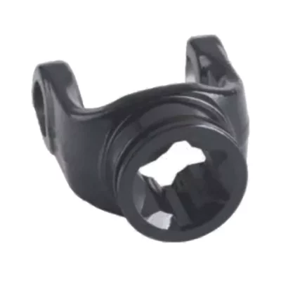
What safety precautions should be followed when working with PTO shaft yokes?
Working with PTO shaft yokes requires adherence to certain safety precautions to prevent accidents and ensure the well-being of operators. Here are some important safety measures to follow:
1. Read and Follow Equipment Manuals: Familiarize yourself with the equipment manufacturer's instructions and safety guidelines provided in the equipment manuals. These manuals often include specific information regarding the safe use, installation, and maintenance of PTO shaft yokes.
2. Wear Appropriate Personal Protective Equipment (PPE): Always wear the recommended personal protective equipment, such as safety glasses, gloves, and appropriate footwear, when working with PTO shaft yokes. PPE helps protect against potential hazards, such as flying debris, sharp edges, or accidental contact with rotating components.
3. Shut off Power Source: Before working on or near PTO shaft yokes, ensure that the power source, such as the engine or tractor, is shut off and the ignition key is removed. This prevents accidental engagement of the yoke and reduces the risk of injury from rotating parts.
4. Engage PTO Safely: When connecting or disconnecting PTO shaft yokes, follow proper procedures to engage or disengage the power take-off (PTO) system. This may involve aligning splines, using safety pins or locking mechanisms, and ensuring secure attachment. Make sure to refer to the equipment manuals for specific instructions.
5. Check for Damage or Wear: Regularly inspect PTO shaft yokes for any signs of wear, damage, or fatigue. If you notice cracks, breaks, worn-out splines, or other abnormalities, refrain from using the yoke and replace it as necessary. Using a damaged yoke can lead to equipment failure or accidents.
6. Maintain Proper Guarding: Ensure that all the necessary guards and shields are in place and properly installed. Guards help prevent accidental contact with rotating components, minimizing the risk of entanglement or injury. Never operate equipment without the appropriate guarding in place.
7. Avoid Loose Clothing and Jewelry: Remove or secure loose clothing, jewelry, and accessories that could get entangled in the PTO shaft or yoke. Loose items can pose a significant hazard if caught in moving parts, leading to severe injuries.
8. Be Cautious of Pinch Points: Exercise caution around pinch points where moving components come into close proximity. Keep hands, fingers, and other body parts away from pinch zones to avoid getting caught or crushed.
9. Provide Training and Supervision: Ensure that individuals operating or working near PTO shaft yokes receive proper training on safe practices and procedures. Supervise inexperienced operators until they are familiar with the equipment and safety protocols.
10. Follow Lockout/Tagout Procedures: When performing maintenance or repairs on equipment involving PTO shaft yokes, follow lockout/tagout procedures as per industry standards. These procedures help ensure that the equipment is properly isolated from energy sources, preventing accidental startup or release of stored energy.
By following these safety precautions, operators can minimize the risks associated with working with PTO shaft yokes and maintain a safe working environment. Remember to prioritize safety at all times and seek professional assistance or guidance when needed.
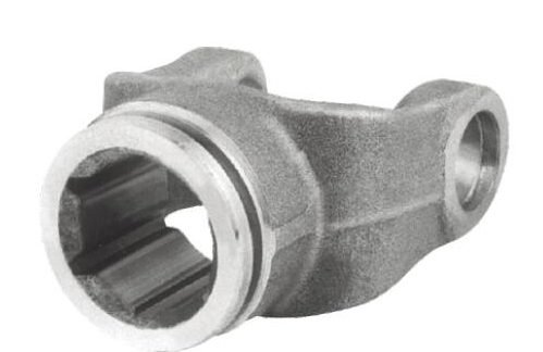
How do PTO shaft yokes ensure efficient power transfer while maintaining stability?
PTO (Power Take-Off) shaft yokes are designed to ensure efficient power transfer while maintaining stability during operation. They incorporate several features and mechanisms to achieve this. Here's a detailed explanation:
1. Splined Connection:
PTO shaft yokes typically have a splined connection with the PTO shaft. The splines on the yoke and the shaft interlock, providing a secure and torque-resistant coupling. This design distributes torque evenly along the length of the splined connection, minimizing stress concentrations and ensuring efficient power transfer.
2. Precise Fit and Tolerance:
PTO shaft yokes are designed with precise tolerances to ensure a proper fit with the PTO shaft. The accurate fit helps maximize torque transfer efficiency and minimizes the risk of slippage or power loss. The tight fit also helps maintain stability by reducing vibrations and minimizing backlash or play between the yoke and the shaft.
3. Balancing:
Some PTO shaft yokes are dynamically balanced to minimize vibrations during operation. Balancing helps ensure smooth rotation and reduces stress on the components. By reducing vibrations, balancing contributes to the stability of the power transmission system and improves overall performance.
4. Quality Materials and Construction:
PTO shaft yokes are typically manufactured using durable materials such as steel or forged alloys. These materials offer strength and stability, allowing the yokes to withstand the high torque and rotational forces involved in power transmission. The robust construction ensures that the yokes can maintain their shape and rigidity, minimizing flexing or deformation that could compromise stability.
5. Support Bearings:
In applications involving long PTO shafts or high loads, support bearings may be used to enhance stability. Support bearings are mounted along the length of the PTO shaft and provide additional support, reducing shaft deflection and maintaining alignment. By minimizing shaft deflection, support bearings help ensure efficient power transfer and reduce the risk of misalignment or vibration-related issues.
6. Design Considerations:
PTO shaft yokes are designed with stability in mind. Factors such as the shape, geometry, and reinforcement of the yoke are carefully considered to enhance stability and minimize the risk of unwanted flexing, bending, or distortion during operation.
By incorporating these features and design considerations, PTO shaft yokes ensure efficient power transfer while maintaining stability. They provide a reliable and robust connection between the power source and the driven equipment, contributing to the overall performance and productivity of the machinery or implement.
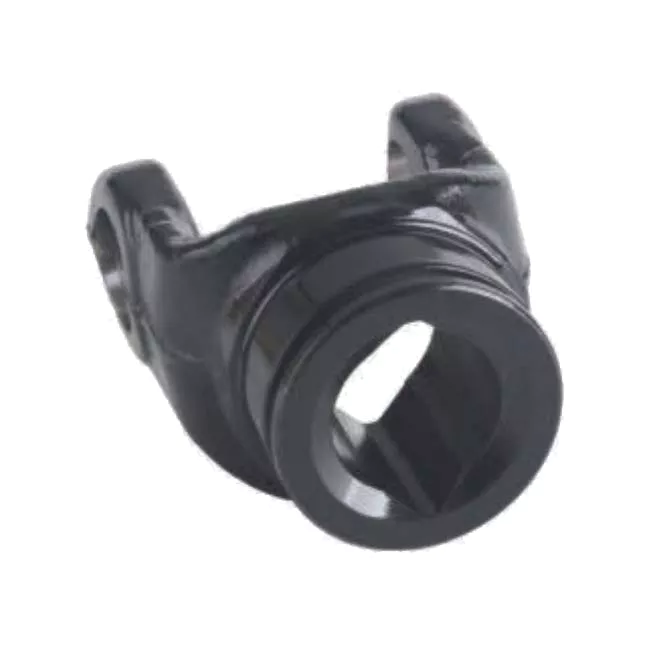
What is a PTO shaft yoke and what role does it play in power transmission?
A PTO (Power Take-Off) shaft yoke is a crucial component in power transmission systems, particularly in vehicles and machinery with PTO capabilities. It serves an important role in transferring power from the engine or power source to the driven equipment. Here's a detailed explanation:
1. Definition: A PTO shaft yoke, also known as a PTO yoke or PTO flange, is a mechanical coupling device that connects the PTO shaft to the driven equipment. It typically consists of a yoke-shaped metal component with a splined bore that securely attaches to the PTO shaft and a mounting flange or connection point that interfaces with the driven equipment.
2. Power Transmission: The primary role of a PTO shaft yoke is to transmit power from the source, such as an engine or power take-off unit, to the driven equipment. It serves as a mechanical link that transfers rotational energy and torque. The PTO shaft yoke connects the rotating output of the power source to the input shaft of the driven equipment, allowing the power to be transmitted and utilized for various tasks.
3. Alignment and Connection: PTO shaft yokes are designed to ensure proper alignment and connection between the PTO shaft and the driven equipment. The splined bore of the yoke securely engages with the splines on the PTO shaft, creating a strong and reliable connection. The mounting flange or connection point of the yoke is designed to align with the corresponding connection on the driven equipment, providing a precise and secure coupling.
4. Flexibility and Articulation: PTO shaft yokes often incorporate flexible or articulating features to accommodate movement and misalignment between the power source and the driven equipment. This flexibility helps compensate for slight angular or positional variations, ensuring smooth power transmission even in dynamic or rugged operating conditions.
5. Maintenance and Safety: PTO shaft yokes require regular inspection and maintenance to ensure their proper functioning and safety. Lubrication of the splined bore and periodic tightening of connection bolts are important maintenance tasks. Additionally, proper guarding and safety measures should be in place to protect operators and bystanders from rotating or exposed PTO shafts.
Overall, a PTO shaft yoke serves as a critical interface between the PTO shaft and the driven equipment, enabling efficient power transmission. Its design and functionality contribute to reliable and precise power delivery, flexibility in accommodating movement and misalignment, and the overall performance and safety of PTO-driven machinery and vehicles.
editor by CX 2023-09-15
China Professional OEM ODM Cardan Transmission Pto Drive Shaft
Product Description
OEM ODM Cardan Transmission Tractor Parts Pto Drive Shaft for Agriculture Machinery
1. Product Description
|
2. More Products
3. The Structure Of PTO Shaft
4. Installing Process
5. Packing and Shipping
6.Our Company
HangZhou CZPT Tech.Machinery Co.,Ltd was founded in 2003. It is located at HangZhou County, HangZhou City, closed to 204 National Road.Our main products: 1. all kinds of drive shaft 2.all kinds of gera box 3. Farm machinery: IMT500 inorganic fertilizer spreader, HMT05S organic fertilizer spreader, 3M rotovator , 3M wet-paddy field rotary, King 185 deep cultviating machine and so on. 4.The machinery parts: many kinds of Gear, Shaft, Flang, ,Gear box, Laser parts, Stamping parts and so on.
7. FAQ
1. Q: Are your products forged or cast?
A: All of our products are forged.
2. Q: What's your MOQ?
A: 20 PCS for each type. We accept the sample order.
3. Q: What's the horse power of the pto shaft are available?
A: We provide a full range of pto shaft, ranging from 16HP-200HP.
4. Q: How many splined specification do you have ?
A: We produce 1 1/8"-Z6, 1 3/8"-Z6, 1 3/4"-Z6, 1 3/8"- Z21, 1 3/4"-Z20, 8X42X48X8 and 8X32X38X6 splines.
5. Q: How about the warranty?
A: We guarantee 1 year warranty. With quality problems, we will send you the new products for free within next shipment.
6. Q: What's your payment terms?
A: T/T, L/C, D/A, D/P….
7. Q: What is the delivery time?
A: 40 days after receiving your advanced deposit.
| Material: | Carbon Steel |
|---|---|
| Load: | Drive Shaft |
| Stiffness & Flexibility: | Stiffness / Rigid Axle |
| Axis Shape: | Straight Shaft |
| Appearance Shape: | Round |
| Processing of Tube: | Cold Drawn |
| Customization: |
Available
| Customized Request |
|---|

How do PTO drive shafts ensure efficient power transfer while maintaining safety?
PTO (Power Take-Off) drive shafts are designed to ensure efficient power transfer while prioritizing safety. These drive shafts incorporate various mechanisms and features to achieve both objectives. Here's a detailed explanation of how PTO drive shafts ensure efficient power transfer while maintaining safety:
1. Robust Construction:
PTO drive shafts are typically constructed using high-quality materials such as steel or composite materials that offer strength and durability. The robust construction allows them to withstand the torque and power demands of the application, ensuring efficient power transfer without excessive flexing or deformation that could result in energy loss or premature failure.
2. Precise Alignment:
Efficient power transfer requires precise alignment between the PTO drive shaft, the primary power source (e.g., engine, transmission), and the implement or equipment being driven. Misalignment can lead to power loss, increased wear, and potential safety hazards. PTO drive shafts are designed with adjustable lengths or flexible couplings to accommodate variations in equipment size and ensure proper alignment, maximizing power transmission efficiency.
3. Connection Safety Features:
PTO drive shafts incorporate safety features to prevent accidents and minimize the risk of injury. One common safety feature is the use of shear pins or torque limiters. These components are designed to break or slip under excessive torque, protecting the drive shaft and connected equipment from damage. By sacrificing the shear pin, the PTO drive shaft disengages in case of overload, ensuring the safety of operators and preventing costly repairs.
4. Overload Protection:
Overload protection mechanisms are crucial for maintaining safety and preventing damage to the PTO drive shaft and associated equipment. Clutch systems or slip clutches can be employed to disengage the drive shaft when excessive torque or speed is encountered. These mechanisms allow the drive shaft to slip or disengage momentarily, preventing damage and reducing the risk of injury to operators or bystanders.
5. Shielding and Guarding:
PTO drive shafts are often equipped with shielding and guarding to prevent contact with moving parts. These protective covers ensure that operators and bystanders are shielded from rotating shafts, universal joints, and other potentially hazardous components. Proper shielding and guarding reduce the risk of entanglement, entrapment, or accidental contact, enhancing overall safety.
6. Compliance with Safety Standards:
PTO drive shafts are designed and manufactured to comply with relevant safety standards and regulations. These standards, such as ISO 500-1, specify requirements for power transmission components, including PTO drive shafts. Compliance with these standards ensures that the drive shafts meet necessary safety criteria and undergo rigorous testing to ensure their reliability and performance.
7. Regular Maintenance and Inspection:
Maintaining the safety and efficiency of PTO drive shafts requires regular maintenance and inspection. Operators should follow recommended maintenance schedules, including lubrication, inspection of components, and replacement of worn or damaged parts. Regular inspections help identify potential safety issues, such as worn bearings, damaged shielding, or compromised safety features, allowing for timely repairs or replacements.
8. Operator Training and Awareness:
Efficient power transfer and safety also depend on operator training and awareness. Operators should receive proper training on the safe operation and maintenance of PTO drive shafts. This includes understanding safety procedures, recognizing potential hazards, and being aware of the risks associated with improper use or maintenance. Promoting a culture of safety and providing ongoing training helps ensure that PTO drive shafts are used correctly and that potential risks are minimized.
By incorporating robust construction, precise alignment, connection safety features, overload protection, shielding and guarding, compliance with safety standards, regular maintenance and inspection, and operator training and awareness, PTO drive shafts can achieve efficient power transfer while maintaining a high level of safety. These measures help prevent accidents, protect equipment and operators, and ensure reliable and effective power transmission in various applications.

How do PTO drive shafts handle variations in load and torque during operation?
PTO (Power Take-Off) drive shafts are designed to handle variations in load and torque during operation, providing a flexible and efficient power transmission solution. They incorporate several mechanisms and features that enable them to accommodate changes in load and torque. Here's how PTO drive shafts handle variations in load and torque:
1. Flexible Couplings:
PTO drive shafts typically utilize flexible couplings, such as universal joints or constant velocity joints, at both ends. These couplings allow for angular misalignment and compensate for variations in load and torque. They can accommodate changes in the orientation and position of the driven equipment relative to the power source, reducing stress on the drive shaft and its components.
2. Spring-Loaded Friction Discs:
Some PTO drive shafts incorporate spring-loaded friction discs, commonly known as torque limiters or overload clutches. These devices provide a mechanical means of protecting the drive shaft and connected equipment from excessive torque. When the torque exceeds a predetermined threshold, the friction discs slip, effectively disconnecting the drive shaft from the power source. This protects the drive shaft from damage and allows the system to handle sudden increases or spikes in torque.
3. Slip Clutches:
Slip clutches are another mechanism used in PTO drive shafts to handle variations in torque. Slip clutches allow controlled slippage between the input and output shafts when a certain torque level is exceeded. They provide a means of limiting torque transmission and protecting the drive shaft from overload. Slip clutches can be adjustable, allowing the desired torque setting to be customized based on the specific application.
4. Torque Converters:
In certain applications, PTO drive shafts may incorporate torque converters. Torque converters are fluid coupling devices that use hydraulic principles to transmit torque. They provide a smooth and gradual ramp-up of torque, which helps in handling variations in load and torque. Torque converters can also provide additional benefits such as dampening vibrations and mitigating shock loads.
5. Load-Bearing Capacity:
PTO drive shafts are designed with sufficient load-bearing capacity to handle variations in load during operation. The material selection, diameter, and wall thickness of the drive shaft are optimized based on the anticipated loads and torque requirements. This allows the drive shaft to effectively transmit power without excessive deflection or deformation, ensuring reliable and efficient operation under different load conditions.
6. Regular Maintenance:
Proper maintenance is essential for the reliable operation of PTO drive shafts. Regular inspection, lubrication, and adjustment of the drive shaft components help ensure optimal performance and longevity. By maintaining the drive shaft in good condition, its ability to handle variations in load and torque can be preserved, reducing the risk of failures or unexpected downtime.
It's important to note that while PTO drive shafts are designed to handle variations in load and torque, there are limits to their capacity. Exceeding the recommended load or torque limits can lead to premature wear, damage to the drive shaft and connected equipment, and compromise safety. It is crucial to operate within the specified parameters and consult the manufacturer's guidelines for the specific PTO drive shaft model being used.
By incorporating flexible couplings, torque limiters, slip clutches, torque converters, and ensuring adequate load-bearing capacity, PTO drive shafts can effectively handle variations in load and torque during operation. These features contribute to the versatility, efficiency, and reliability of PTO drive shaft systems across a wide range of applications.
Are there different types of PTO drive shaft configurations based on equipment type?
Yes, there are different types of PTO (Power Take-Off) drive shaft configurations based on the type of equipment they are used with. PTO drive shafts are designed to accommodate the specific requirements of different equipment types, ensuring efficient power transmission and compatibility. Here's a detailed explanation of some common PTO drive shaft configurations based on equipment type:
1. Tractor PTO Drive Shafts:
Tractors are one of the primary vehicles that utilize PTO drive shafts. Tractor PTO drive shafts are typically configured with a splined connection on one end to attach to the tractor's PTO output shaft, and a corresponding splined connection on the other end to connect to implements or machinery. The length of the drive shaft can often be adjusted to accommodate variations in equipment sizes and operating conditions. Tractor PTO drive shafts are commonly used in agriculture, landscaping, and other applications where tractors are the primary power source.
2. Implement PTO Drive Shafts:
Implement PTO drive shafts are designed specifically for various types of implements and machinery. These drive shafts often have a splined connection on one end to attach to the implement input shaft, while the other end may have a different type of connection depending on the implement's design. The specific configuration of implement PTO drive shafts can vary widely based on the implement type, such as mowers, balers, tillers, seeders, sprayers, and harvesters. Implement PTO drive shafts are commonly used in agriculture, construction, and other industries where implements are powered by a primary power source.
3. Truck PTO Drive Shafts:
Trucks, especially heavy-duty trucks, often utilize PTO drive shafts for powering various auxiliary equipment and systems. Truck PTO drive shafts are typically designed to transmit power from the truck's engine or transmission to hydraulic systems, winches, cranes, or other equipment mounted on the truck. These drive shafts may have different configurations depending on the specific truck model and the intended application. Truck PTO drive shafts can handle higher torque and power requirements compared to drive shafts used in smaller vehicles.
4. Industrial PTO Drive Shafts:
Industrial applications often require PTO drive shafts to power machinery and equipment in sectors such as mining, manufacturing, material handling, and processing. Industrial PTO drive shafts are designed to handle heavy-duty operations and can vary in configuration based on the specific machinery requirements. They may incorporate features such as reinforced construction, larger diameter shafts, and specialized coupling mechanisms to accommodate high torque, speed, and power demands.
5. Specialty PTO Drive Shafts:
In addition to the commonly used configurations mentioned above, there are also specialty PTO drive shafts designed for specific applications. These can include drive shafts for specialized machinery in sectors such as forestry, oil and gas, marine, and construction. These specialty drive shafts may have unique configurations and features tailored to the specific requirements and operating conditions of the equipment they are intended to power.
Overall, PTO drive shaft configurations can vary based on the equipment type and the specific application. The design considerations include factors such as the type of connection, length adjustment mechanisms, torque and power handling capabilities, and any specialized features required by the equipment. By employing different PTO drive shaft configurations, various equipment types can efficiently transfer power from a primary power source to implements, machinery, or auxiliary systems.
editor by CX 2023-09-15
China OEM Custom CNC Shaft 304 CNC Machined Long Shaft Motor Drive Shaft
Product Description
Product Description
|
Company Profile
HangZhou Xihu (West Lake) Dis. Machinery Manufacture Co., Ltd., located in HangZhou, "China's ancient copper capital", is a "national high-tech enterprise". At the beginning of its establishment, the company adhering to the "to provide clients with high quality products, to provide timely service" concept, adhere to the "everything for the customer, make customer excellent supplier" for the mission.
Certifications
Q: Where is your company located ?
A: HangZhou ZheJiang .
Q: How could l get a sample?
A: Before we received the first order, please afford the sample cost and express fee. we will return the sample cost back
to you within your first order.
Q: Sample time?
A: Existing items: within 20-60 days.
Q: Whether you could make our brand on your products?
A: Yes. We can print your Logo on both the products and the packages if you can meet our MOQ.
Q: How to guarantee the quality of your products?
A: 1) stict detection during production. 2) Strict completely inspecion on products before shipment and intact product
packaging ensured.
Q: lf my drawings are safe?
A: Yes ,we can CZPT NDA.
| Material: | Carbon Steel |
|---|---|
| Load: | Drive Shaft |
| Stiffness & Flexibility: | Stiffness / Rigid Axle |
| Journal Diameter Dimensional Accuracy: | OEM/ODM/Customized |
| Axis Shape: | Straight Shaft |
| Shaft Shape: | OEM/ODM/Customized |
| Customization: |
Available
| Customized Request |
|---|

What maintenance practices are crucial for prolonging the lifespan of drive shafts?
To prolong the lifespan of drive shafts and ensure their optimal performance, several maintenance practices are crucial. Regular maintenance helps identify and address potential issues before they escalate, reduces wear and tear, and ensures the drive shaft operates smoothly and efficiently. Here are some essential maintenance practices for prolonging the lifespan of drive shafts:
1. Regular Inspection:
Performing regular inspections is vital for detecting any signs of wear, damage, or misalignment. Inspect the drive shaft visually, looking for cracks, dents, or any signs of excessive wear on the shaft itself and its associated components such as joints, yokes, and splines. Check for any signs of lubrication leaks or contamination. Additionally, inspect the fasteners and mounting points to ensure they are secure. Early detection of any issues allows for timely repairs or replacements, preventing further damage to the drive shaft.
2. Lubrication:
Proper lubrication is essential for the smooth operation and longevity of drive shafts. Lubricate the joints, such as universal joints or constant velocity joints, as recommended by the manufacturer. Lubrication reduces friction, minimizes wear, and helps dissipate heat generated during operation. Use the appropriate lubricant specified for the specific drive shaft and application, considering factors such as temperature, load, and operating conditions. Regularly check the lubrication levels and replenish as necessary to ensure optimal performance and prevent premature failure.
3. Balancing and Alignment:
Maintaining proper balancing and alignment is crucial for the lifespan of drive shafts. Imbalances or misalignments can lead to vibrations, accelerated wear, and potential failure. If vibrations or unusual noises are detected during operation, it is important to address them promptly. Perform balancing procedures as necessary, including dynamic balancing, to ensure even weight distribution along the drive shaft. Additionally, verify that the drive shaft is correctly aligned with the engine or power source and the driven components. Misalignment can cause excessive stress on the drive shaft, leading to premature failure.
4. Protective Coatings:
Applying protective coatings can help prolong the lifespan of drive shafts, particularly in applications exposed to harsh environments or corrosive substances. Consider using coatings such as zinc plating, powder coating, or specialized corrosion-resistant coatings to enhance the drive shaft's resistance to corrosion, rust, and chemical damage. Regularly inspect the coating for any signs of degradation or damage, and reapply or repair as necessary to maintain the protective barrier.
5. Torque and Fastener Checks:
Ensure that the drive shaft's fasteners, such as bolts, nuts, or clamps, are properly torqued and secured according to the manufacturer's specifications. Loose or improperly tightened fasteners can lead to excessive vibrations, misalignment, or even detachment of the drive shaft. Periodically check and retighten the fasteners as recommended or after any maintenance or repair procedures. Additionally, monitor the torque levels during operation to ensure they remain within the specified range, as excessive torque can strain the drive shaft and lead to premature failure.
6. Environmental Protection:
Protecting the drive shaft from environmental factors can significantly extend its lifespan. In applications exposed to extreme temperatures, moisture, chemicals, or abrasive substances, take appropriate measures to shield the drive shaft. This may include using protective covers, seals, or guards to prevent contaminants from entering and causing damage. Regular cleaning of the drive shaft, especially in dirty or corrosive environments, can also help remove debris and prevent buildup that could compromise its performance and longevity.
7. Manufacturer Guidelines:
Follow the manufacturer's guidelines and recommendations for maintenance practices specific to the drive shaft model and application. The manufacturer's instructions may include specific intervals for inspections, lubrication, balancing, or other maintenance tasks. Adhering to these guidelines ensures that the drive shaft is properly maintained and serviced, maximizing its lifespan and minimizing the risk of unexpected failures.
By implementing these maintenance practices, drive shafts can operate reliably, maintain efficient power transmission, and have an extended service life, ultimately reducing downtime and ensuring optimal performance in various applications.
What safety precautions should be followed when working with drive shafts?
Working with drive shafts requires adherence to specific safety precautions to prevent accidents, injuries, and damage to equipment. Drive shafts are critical components of a vehicle or machinery's driveline system and can pose hazards if not handled properly. Here's a detailed explanation of the safety precautions that should be followed when working with drive shafts:
1. Personal Protective Equipment (PPE):
Always wear appropriate personal protective equipment when working with drive shafts. This may include safety goggles, gloves, steel-toed boots, and protective clothing. PPE helps protect against potential injuries from flying debris, sharp edges, or accidental contact with moving parts.
2. Lockout/Tagout Procedures:
Before working on a drive shaft, ensure that the power source is properly locked out and tagged out. This involves isolating the power supply, such as shutting off the engine or disconnecting the electrical power, and securing it with a lockout/tagout device. This prevents accidental engagement of the drive shaft while maintenance or repair work is being performed.
3. Vehicle or Equipment Support:
When working with drive shafts in vehicles or equipment, use proper support mechanisms to prevent unexpected movement. Securely block the vehicle's wheels or utilize support stands to prevent the vehicle from rolling or shifting during drive shaft removal or installation. This helps maintain stability and reduces the risk of accidents.
4. Proper Lifting Techniques:
When handling heavy drive shafts, use proper lifting techniques to prevent strain or injuries. Lift with the help of a suitable lifting device, such as a hoist or jack, and ensure that the load is evenly distributed and securely attached. Avoid lifting heavy drive shafts manually or with improper lifting equipment, as this can lead to accidents and injuries.
5. Inspection and Maintenance:
Prior to working on a drive shaft, thoroughly inspect it for any signs of damage, wear, or misalignment. If any abnormalities are detected, consult a qualified technician or engineer before proceeding. Regular maintenance is also essential to ensure the drive shaft is in good working condition. Follow the manufacturer's recommended maintenance schedule and procedures to minimize the risk of failures or malfunctions.
6. Proper Tools and Equipment:
Use appropriate tools and equipment specifically designed for working with drive shafts. Improper tools or makeshift solutions can lead to accidents or damage to the drive shaft. Ensure that tools are in good condition, properly sized, and suitable for the task at hand. Follow the manufacturer's instructions and guidelines when using specialized tools or equipment.
7. Controlled Release of Stored Energy:
Some drive shafts, particularly those with torsional dampers or other energy-storing components, can store energy even when the power source is disconnected. Exercise caution when working on such drive shafts and ensure that the stored energy is safely released before disassembly or removal.
8. Training and Expertise:
Work on drive shafts should only be performed by individuals with the necessary training, knowledge, and expertise. If you are not familiar with drive shafts or lack the required skills, seek assistance from qualified technicians or professionals. Improper handling or installation of drive shafts can lead to accidents, damage, or compromised performance.
9. Follow Manufacturer's Guidelines:
Always follow the manufacturer's guidelines, instructions, and warnings specific to the drive shaft you are working with. These guidelines provide important information regarding installation, maintenance, and safety considerations. Deviating from the manufacturer's recommendations may result in unsafe conditions or void warranty coverage.
10. Disposal of Old or Damaged Drive Shafts:
Dispose of old or damaged drive shafts in accordance with local regulations and environmental guidelines. Improper disposal can have negative environmental impacts and may violate legal requirements. Consult with local waste management authorities or recycling centers to ensure appropriate disposal methods are followed.
By following these safety precautions, individuals can minimize the risks associated with working with drive shafts and promote a safe working environment. It is crucial to prioritize personal safety, use proper equipment and techniques, and seek professional help when needed to ensure the proper handling and maintenance of drive shafts.
What is a drive shaft and how does it function in vehicles and machinery?
A drive shaft, also known as a propeller shaft or prop shaft, is a mechanical component that plays a critical role in transmitting rotational power from the engine to the wheels or other driven components in vehicles and machinery. It is commonly used in various types of vehicles, including cars, trucks, motorcycles, and agricultural or industrial machinery. Here's a detailed explanation of what a drive shaft is and how it functions:
1. Definition and Construction: A drive shaft is a cylindrical metal tube that connects the engine or power source to the wheels or driven components. It is typically made of steel or aluminum and consists of one or more tubular sections with universal joints (U-joints) at each end. These U-joints allow for angular movement and compensation of misalignment between the engine/transmission and the driven wheels or components.
2. Power Transmission: The primary function of a drive shaft is to transmit rotational power from the engine or power source to the wheels or driven components. In vehicles, the drive shaft connects the transmission or gearbox output shaft to the differential, which then transfers power to the wheels. In machinery, the drive shaft transfers power from the engine or motor to various driven components such as pumps, generators, or other mechanical systems.
3. Torque and Speed: The drive shaft is responsible for transmitting both torque and rotational speed. Torque is the rotational force generated by the engine or power source, while rotational speed is the number of revolutions per minute (RPM). The drive shaft must be capable of transmitting the required torque without excessive twisting or bending and maintaining the desired rotational speed for efficient operation of the driven components.
4. Flexible Coupling: The U-joints on the drive shaft provide a flexible coupling that allows for angular movement and compensation of misalignment between the engine/transmission and the driven wheels or components. As the suspension system of a vehicle moves or the machinery operates on uneven terrain, the drive shaft can adjust its length and angle to accommodate these movements, ensuring smooth power transmission and preventing damage to the drivetrain components.
5. Length and Balance: The length of the drive shaft is determined by the distance between the engine or power source and the driven wheels or components. It should be appropriately sized to ensure proper power transmission and avoid excessive vibrations or bending. Additionally, the drive shaft is carefully balanced to minimize vibrations and rotational imbalances, which can cause discomfort, reduce efficiency, and lead to premature wear of drivetrain components.
6. Safety Considerations: Drive shafts in vehicles and machinery require proper safety measures. In vehicles, drive shafts are often enclosed within a protective tube or housing to prevent contact with moving parts and reduce the risk of injury in the event of a malfunction or failure. Additionally, safety shields or guards are commonly installed around exposed drive shafts in machinery to protect operators from potential hazards associated with rotating components.
7. Maintenance and Inspection: Regular maintenance and inspection of drive shafts are essential to ensure their proper functioning and longevity. This includes checking for signs of wear, damage, or excessive play in the U-joints, inspecting the drive shaft for any cracks or deformations, and lubricating the U-joints as recommended by the manufacturer. Proper maintenance helps prevent failures, ensures optimal performance, and prolongs the service life of the drive shaft.
In summary, a drive shaft is a mechanical component that transmits rotational power from the engine or power source to the wheels or driven components in vehicles and machinery. It functions by providing a rigid connection between the engine/transmission and the driven wheels or components, while also allowing for angular movement and compensation of misalignment through the use of U-joints. The drive shaft plays a crucial role in power transmission, torque and speed delivery, flexible coupling, length and balance considerations, safety, and maintenance requirements. Its proper functioning is essential for the smooth and efficient operation of vehicles and machinery.
editor by CX 2023-09-15
China OEM CE Certification Agricultural Wide Angle Tractor Factory Supply 6 Spline 540 Pto Drive Shaft for Bush Hog with Yoke Adapter Parts
Product Description
CE Certification Agricultural Wide Angle Tractor Factory Supply 6 Spline 540 Pto Drive Shaft for Bush Hog with Yoke Adapter Parts
Product Description
PTO drive shaft
Brand New Replacement PTO shaft for Finish Mowers, Tillers, Spreaders, Hay Tedders and many more applications.
PTO is a series 4, rated for 40HP it has 1-3/8" 6 spline push pin on both ends for easy installment. Complete with safety shield, The PTO measures 43" from end to end and has an 58" maximum extended length.
These PTO shafts fit the following Finish Mowers:
Bush Hog: ATH 600 and ATH 720, ATH 900, FTH 480, FTH 600, FTH 720, MTH 600, MTH 720 Series Mowers;
Landpride: FDR1548, FDR1560, FDR1572, FDR1648, FDR1660, FDR1672, FDR2548, FDR2560, FDR2572, AT2660, AT2672 Series Mowers;
Kubota: BL348A, B342A; Caroni TC480, TC590, TC710, TC910 with spline Input Shaft;
Ever-power most late models with splined input shafts, early models had some with smooth input shaft;
1. PTO Drive Shafts
PTO SHAFT WITH QUICK RELEASE YOKES AND OVER-RUNNING CLUTCH(RA), YOU CAN CHOOSE THE LENGTH
Chinabase is a professional manufacturer of PTO SHAFTS for farm machines and agricultural tractors from China. We provide more than 8 sizes of PTO shafts. There is also a full range of safety devices for agricultural applications. Our products are sold to America, Europe and all over the world. We will supply best quality products in most reasonable price.
Following are the tips how to order your PTO shafts:
2. Closed overall length (or cross to cross) of a PTO shaft.
3. Tubes or Pipes
We've already got Triangular profile tube and Lemon profile tube for all the series we provide.
And we have some star tube, splined tube and other profile tubes but only for a certain sizes.
4. End yokes
We've got 13 types of splined yokes and 8 types of plain bore yokes. I will suggest the usual type for your reference.
You can also send drawings or pictures to us if you cannot find your item in our catalog.
5. Safety devices or clutches
I will attach the details of safety devices for your reference. We've already have Free wheel (RA), Ratchet torque limiter(SA),
Shear bolt torque limiter(SB), 3types of friction torque limiter (FF,FFS,FCS) and overrunning couplers(adapters) (FAS).
6. For any other more special requirements with plastic guard, connection method, color of painting, package, etc., please feel free to let me know.
Tube types
| Spline tube | Lemon tube |
| Star tube | Trigonal tube |
|
Function of PTO Shaft |
Drive Shaft Parts & Power Transmission |
|
Usage of PTO Shaft |
Kinds of Tractors & Farm Implements |
|
Yoke Types for PTO Shaft |
Double push pin, Bolt pins, Split pins, Pushpin, Quick release, Ball attachment, Collar….. |
|
Processing Of Yoke |
Forging |
|
PTO Shaft Plastic Cover |
YW; BW; YS; BS; Etc |
|
Colors of PTO Shaft |
Green; Orange; Yellow; Black Ect. |
|
PTO Shaft Series |
T1-T10; L1-L6;S6-S10;10HP-150HP with SA,RA,SB,SFF,WA,CV Etc |
|
Tube Types for PTO Shaft |
Lemon, Triangular, Star, Square, Hexangular, Spline, Special Ect |
|
Processing Of Tube |
Cold drawn |
|
Spline Types for PTO Shaft |
1 1/8″ Z6;1 3/8″ Z6; 1 3/8″ Z21 ;1 3/4″ Z20; 1 3/4″ Z6; 8-38*32*6 8-42*36*7; 8-48*42*8; |
Application
Company Profile
Our factory is a leading manufacturer of PTO shaft yoke and universal joint.
We manufacture high quality PTO yokes for various vehicles, construction machinery and equipment. All products are constructed with rotating lighter.
We are currently exporting our products throughout the world, especially to North America, South America, Europe, and Russia. If you are interested in any item, please do not hesitate to contact us. We are looking CHINAMFG to becoming your suppliers in the near future.
Packaging & Shipping
Certifications
Related products
You can click the picture to learn about relevant products
Installation Instructions
PTO SHAFT INSTALLATION INSTRUCTION
Install assembly
1 press-fit plastic pipe and plastic cap,
2 fill the groove on the CHINAMFG with oil
3. Slide the nylon bearing into the groove 4. Align nylon bearing and plastic protective cover
Disassembly
1. remove the nylon bearing clamp (three places) with a screwdriver, and then separate the steel pipe and plastic protective cover.
2. Take off the nylon bearing from the groove of the yokes.
3. repeat the above-mentioned steps for the other side.
SHORTENING THE PTO DRIVESHAFT
1. Remove the safety shield.
2. Shorten the inner and outer tubes according to the required length, and the inner and outer tubes shall be shortened by the same length at 1 time
3. Deburr edges of the drive tubes with a file and remove all filings from the tubes.
4. Shorten the inner and outer plastic pipes according to the required length, and the inner and outer plastic pipes shall be
shortened by the same length at 1 time.
5. Grease the internal drive tubes and reassemble them with a safety shield.
Check the minimum and maximum length of the driveshaft installed on the machine. In working condition, the drive tubes should overlap 2/3 length and the plastic tube should never be separated
| Material: | Carbon Steel |
|---|---|
| Load: | Drive Shaft |
| Stiffness & Flexibility: | Flexible Shaft |
| Journal Diameter Dimensional Accuracy: | IT6-IT9 |
| Axis Shape: | Straight Shaft |
| Shaft Shape: | Real Axis |
| Samples: |
US$ 9999/Piece
1 Piece(Min.Order) | |
|---|
How do manufacturers ensure the compatibility of PTO shafts with different equipment?
Manufacturers employ various measures to ensure the compatibility of PTO (Power Take-Off) shafts with different equipment. Compatibility is crucial to ensure that PTO shafts can effectively transfer power from the power source to the driven machinery without compromising performance, safety, or ease of use. Here's a detailed explanation of how manufacturers ensure compatibility:
1. Standardization: PTO shafts are designed and manufactured based on standardized specifications. These specifications outline the essential parameters such as shaft dimensions, spline sizes, torque ratings, and safety requirements. By adhering to standardized designs, manufacturers ensure that PTO shafts are compatible with a wide range of equipment that meets the same standards. Standardization allows for interchangeability, meaning that PTO shafts from one manufacturer can be used with equipment from another manufacturer as long as they conform to the same specifications.
2. Collaboration with Equipment Manufacturers: PTO shaft manufacturers often collaborate closely with equipment manufacturers to ensure compatibility. They work together to understand the specific requirements of the equipment and design PTO shafts that seamlessly integrate with the machinery. This collaboration may involve sharing technical specifications, conducting joint testing, and exchanging feedback. By working in partnership, manufacturers can address any compatibility issues early in the design and development process, resulting in PTO shafts that are tailored to the equipment's needs.
3. Customization Options: PTO shaft manufacturers offer customization options to accommodate different equipment configurations. They provide flexibility in terms of shaft length, spline sizes, yoke designs, and coupling mechanisms. Equipment manufacturers can specify the required parameters, and the PTO shafts can be customized accordingly. This ensures that the PTO shafts precisely match the equipment's power input/output requirements and connection methods, guaranteeing compatibility and efficient power transfer.
4. Testing and Validation: Manufacturers conduct rigorous testing and validation processes to ensure the compatibility and performance of PTO shafts. They subject the shafts to various tests, including torque testing, rotational speed testing, and durability testing. These tests verify that the PTO shafts can handle the expected power loads and operating conditions without failure. By validating the performance of the PTO shafts, manufacturers can ensure that they are compatible with a wide range of equipment and can reliably transfer power under different operating scenarios.
5. Compliance with Industry Standards: PTO shaft manufacturers adhere to industry standards and regulations to ensure compatibility. Organizations such as the American Society of Agricultural and Biological Engineers (ASABE) establish safety and performance standards for PTO shafts. Manufacturers design and produce their shafts in accordance with these standards, ensuring that their products meet the necessary requirements for compatibility and safety. Compliance with industry standards provides assurance to equipment manufacturers and end-users that the PTO shafts are compatible and suitable for use with different equipment.
6. Documentation and Guidelines: Manufacturers provide comprehensive documentation and guidelines to assist equipment manufacturers and end-users in ensuring compatibility. This documentation includes technical specifications, installation instructions, maintenance guidelines, and safety recommendations. The documentation helps equipment manufacturers select the appropriate PTO shaft for their equipment and provides guidance on proper installation and use. By following the manufacturer's guidelines, equipment manufacturers can ensure compatibility and optimize the performance of the PTO shafts.
7. Ongoing Research and Development: PTO shaft manufacturers continuously invest in research and development to enhance compatibility with different equipment. They stay updated with industry trends, technological advancements, and evolving equipment requirements. This ongoing research and development enable manufacturers to improve the design, materials, and features of PTO shafts, ensuring compatibility with the latest equipment innovations and addressing any compatibility challenges that may arise.
By employing standardization, collaborating with equipment manufacturers, offering customization options, conducting thorough testing, complying with industry standards, providing documentation and guidelines, and investing in research and development, manufacturers ensure the compatibility of PTO shafts with different equipment. This compatibility allows for seamless integration, efficient power transfer, and optimal performance across a wide range of machinery and equipment in various industries.
How do PTO shafts handle variations in load and torque during operation?
PTO (Power Take-Off) shafts are designed to handle variations in load and torque during operation by employing specific mechanisms and features that ensure efficient power transfer and protection against overload conditions. Here's a detailed explanation of how PTO shafts handle variations in load and torque:
1. Mechanical Design: PTO shafts are engineered with robust mechanical design principles that enable them to handle variations in load and torque. They are typically constructed using high-strength materials such as steel, which provides durability and resistance to bending or twisting forces. The shaft's diameter, wall thickness, and overall dimensions are carefully calculated to withstand the expected torque levels and load variations. The mechanical design of the PTO shaft ensures that it can transmit power reliably and accommodate the dynamic forces encountered during operation.
2. Universal Joints: Universal joints are a key component of PTO shafts that allow for flexibility and compensation of misalignment between the power source and driven machinery. These joints can accommodate variations in angular alignment, which may occur due to changes in load or movement of the machinery. Universal joints consist of a cross-shaped yoke with needle bearings that allow for smooth rotation and transfer of torque, even when the shafts are not perfectly aligned. The design of universal joints enables PTO shafts to handle variations in load and torque while maintaining consistent power transmission.
3. Slip Clutches: Slip clutches are often incorporated into PTO shafts to provide overload protection. These clutches allow the PTO shaft to slip or disengage momentarily when excessive torque or resistance is encountered. Slip clutches typically consist of friction plates that can be adjusted to a specific torque setting. When the torque surpasses the predetermined limit, the clutch slips, preventing damage to the PTO shaft and connected equipment. Slip clutches are particularly useful when sudden changes in load or torque occur, providing a safety mechanism to protect the PTO shaft and associated machinery.
4. Torque Limiters: Torque limiters are another protective feature found in some PTO shafts. These devices are designed to automatically disengage the power transmission when a predetermined torque threshold is exceeded. Torque limiters can be mechanical, such as shear pin couplings or friction clutches, or electronic, utilizing sensors and control systems. When the torque exceeds the set limit, the torque limiter disengages, preventing further power transfer and protecting the PTO shaft from overload conditions. Torque limiters are effective in handling sudden spikes in torque and safeguarding the PTO shaft and associated equipment.
5. Maintenance and Inspection: Regular maintenance and inspection of PTO shafts are essential to ensure their proper functioning and ability to handle variations in load and torque. Routine maintenance includes lubrication of universal joints, inspection of shaft integrity, and tightening of fasteners. Regular inspections allow for early detection of wear, misalignment, or other issues that may affect the PTO shaft's performance. By addressing maintenance and inspection requirements, operators can identify and address any concerns that may arise due to variations in load and torque, ensuring the continued safe and efficient operation of the PTO shaft.
6. Operator Awareness and Control: Operators play a crucial role in managing variations in load and torque during PTO shaft operation. They should be aware of the machinery's operational limits, including the recommended torque ratings and load capacities of the PTO shaft. Proper training and understanding of the equipment's capabilities enable operators to make informed decisions and adjust the operation when encountering significant load or torque changes. Operators should also be vigilant in monitoring the equipment's performance, watching for any signs of excessive vibration, noise, or other indications of potential issues related to load and torque variations.
By incorporating robust mechanical design, utilizing universal joints, slip clutches, torque limiters, and implementing proper maintenance practices, PTO shafts are equipped to handle variations in load and torque during operation. These features ensure reliable power transmission, protect against overload conditions, and contribute to the safe and efficient functioning of the PTO shaft and the machinery it drives.
Can you explain the different types of PTO shafts and their applications?
PTO shafts (Power Take-Off shafts) come in various types, each designed for specific applications and requirements. The different types of PTO shafts offer versatility and compatibility with a wide range of machinery and implements. Here's an explanation of the most common types of PTO shafts and their applications:
1. Standard PTO Shaft: The standard PTO shaft, also known as a splined shaft, is the most common type used in agricultural and industrial machinery. It consists of a solid steel shaft with splines or grooves along its length. The standard PTO shaft typically has six splines, although variations with four or eight splines can be found. This type of PTO shaft is widely used in tractors and various implements, including mowers, balers, tillers, and rotary cutters. The splines provide a secure connection between the power source and the driven machinery, ensuring efficient power transfer.
2. Shear Bolt PTO Shaft: Shear bolt PTO shafts are designed with a safety feature that allows the shaft to separate in case of overload or sudden shock to protect the driveline components. These PTO shafts incorporate a shear bolt mechanism that connects the tractor's power take-off to the driven machinery. In the event of excessive load or sudden resistance, the shear bolt is designed to break, disconnecting the PTO shaft and preventing damage to the driveline. Shear bolt PTO shafts are commonly used in equipment that may encounter sudden obstructions or high-stress situations, such as wood chippers, stump grinders, and heavy-duty rotary cutters.
3. Friction Clutch PTO Shaft: Friction clutch PTO shafts feature a clutch mechanism that allows for smooth engagement and disengagement of the power transfer. These PTO shafts typically incorporate a friction disc and a pressure plate, similar to a traditional vehicle clutch system. The friction clutch allows operators to gradually engage or disengage the power transfer, reducing shock loads and minimizing wear on the driveline components. Friction clutch PTO shafts are commonly used in applications where precise control of power engagement is required, such as in hydraulic pumps, generators, and industrial mixers.
4. Constant Velocity (CV) PTO Shaft: Constant Velocity (CV) PTO shafts, also known as homokinetic shafts, are designed to accommodate high angles of misalignment without affecting power transmission. They use a universal joint mechanism that allows for smooth power transfer even when the driven machinery is at an angle relative to the power source. CV PTO shafts are frequently used in applications where the machinery requires a significant range of movement or articulation, such as in articulated loaders, telescopic handlers, and self-propelled sprayers.
5. Telescopic PTO Shaft: Telescopic PTO shafts are adjustable in length, allowing for flexibility in equipment configuration and varying distances between the power source and the driven machinery. They consist of two or more concentric shafts that slide within each other, providing the ability to extend or retract the PTO shaft as needed. Telescopic PTO shafts are commonly used in applications where the distance between the tractor's power take-off and the implement varies, such as in front-mounted implements, snow blowers, and self-loading wagons. The telescopic design enables easy adaptation to different equipment setups and minimizes the risk of the PTO shaft dragging on the ground.
6. Gearbox PTO Shaft: Gearbox PTO shafts are designed to adapt power transmission between different rotational speeds or directions. They incorporate a gearbox mechanism that allows for speed reduction or increase, as well as the ability to change rotational direction. Gearbox PTO shafts are commonly used in applications where the driven machinery requires a different speed or rotational direction than the tractor's power take-off. Examples include grain augers, feed mixers, and industrial equipment that requires specific speed ratios or reversing capabilities.
It's important to note that the availability and specific applications of PTO shaft types may vary based on regional and industry-specific factors. Additionally, certain machinery or implements may require specialized or custom PTO shafts to meet specific requirements.
In summary, the different types of PTO shafts, such as standard, shear bolt, friction clutch, constant velocity (CV), telescopic, and gearbox shafts, offer versatility and compatibility with various machinery and implements. Each type of PTO shaft is designed to address specific needs, such as power transfer efficiency, safety, smooth engagement, misalignment tolerance, adaptability, and speed/direction adjustment. Understanding the different types of PTO shafts and their applications is crucial for selecting the appropriate shaft forthe intended machinery and ensuring optimal performance and reliability.
editor by CX 2023-09-14