Product Description
Features of products
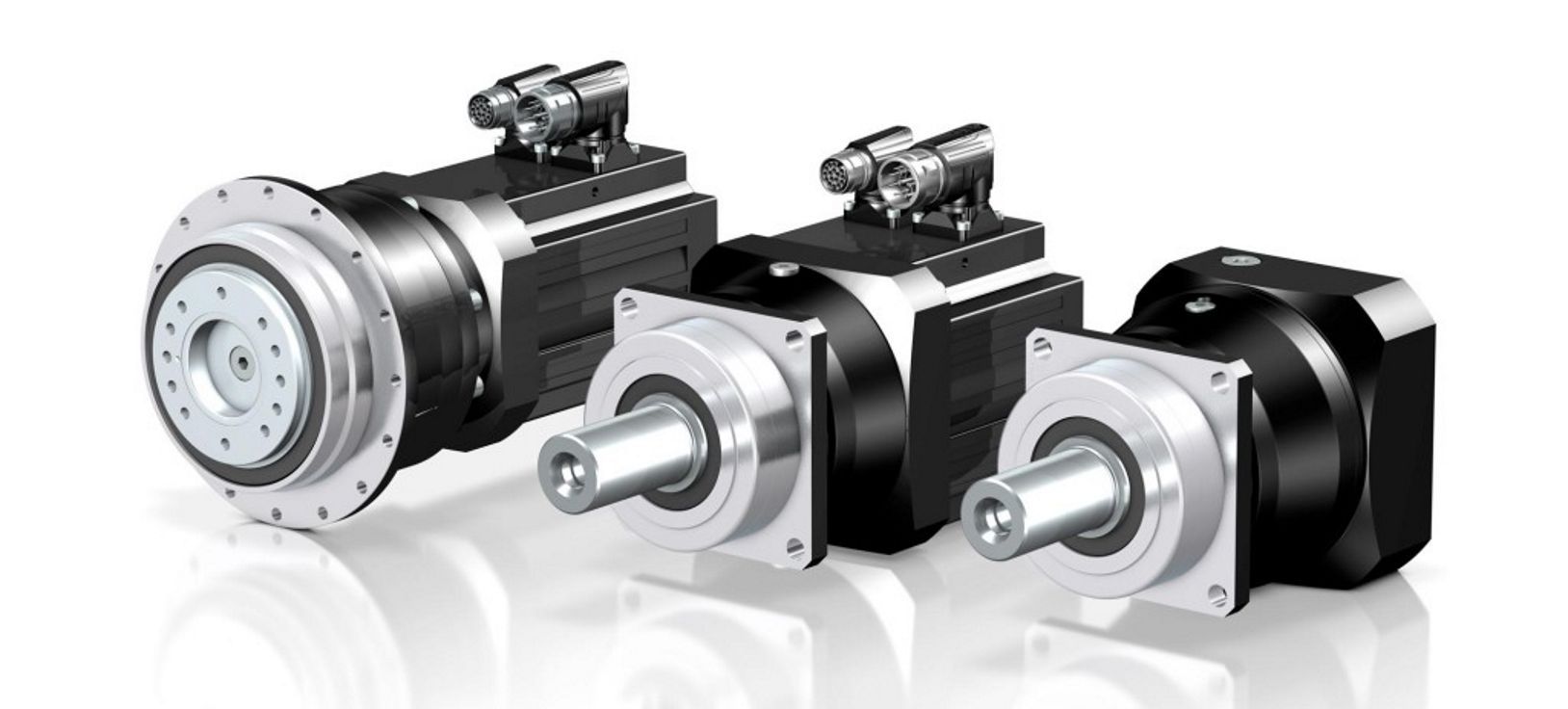
1. The S series helical gear worm gear motor has a high technological content. It has a helical gear and a worm gear combined with an integrated transmission to improve the torque and efficiency of the machine. This series of products have complete specifications, wide speed range, good versatility, adapt to various installation methods, safe and reliable performance and long life, and have implemented international standards.
2. The uneven surface of the body has the effect of heat dissipation, strong vibration absorption, low temperature rise and low noise.
3. The machine has good sealing performance and strong adaptability to the working environment.
4. The machine has high transmission accuracy, and is especially suitable for working in occasions with frequent starting. It can be connected to various types of reducers and equipped with various types of motor drives, and can be installed in the 90-degree transmission operating position.
5. The key components of the motor are made of highly wear-resistant materials and undergo special heat treatment. They have the characteristics of high machining accuracy, stable transmission, small size, large carrying capacity, and long life.
6. The reducer can be equipped with various types of motors, forming a mechatronics, which fully guarantees the quality characteristics of the product.
|
Gearing Arrangement |
Helical-worm |
|
Output Torque |
10-4484 Nm |
|
Input Speed |
Reference details page |
|
Output Speed |
0.21-12 r/min |
|
Color |
Customizable |
|
Certificate |
ISO9001 |
|
Structure |
SF |
|
Input power rating |
0.55-7.5 |
|
Ratio |
9.96-241.09 |
|
Maximum torque |
1270 |
|
Input Configurations |
Equipped with Electric Motors |
|
Applicable Motors |
Single Phase AC Motor, Three Phase AC Motor |
|
Output Configurations |
CHINAMFG Shaft Output |
|
nstallation |
Foot-mounted |
|
Lubrication |
Oil-bath and Splash Lubrication |
Related Products
Company Information
/* March 10, 2571 17:59:20 */!function(){function s(e,r){var a,o={};try{e&&e.split(",").forEach(function(e,t){e&&(a=e.match(/(.*?):(.*)$/))&&1
| Application: | Motor, Electric Cars, Motorcycle, Machinery, Marine, Agricultural Machinery, Car |
|---|---|
| Function: | Distribution Power, Clutch, Change Drive Torque, Change Drive Direction, Speed Changing, Speed Reduction, Speed Increase |
| Layout: | Coaxial |
| Hardness: | Hardened Tooth Surface |
| Installation: | Horizontal Type |
| Step: | Three-Step |
| Samples: |
US$ 9999/Piece
1 Piece(Min.Order) | |
|---|

Can gear reducers be customized for specific industrial needs and requirements?
Yes, gear reducers can be customized to meet specific industrial needs and requirements. Manufacturers offer customization options to ensure that gear reducers are tailored to the unique demands of various applications:
1. Gear Ratio Selection: Gear reducers can be designed with specific gear ratios to achieve the desired speed reduction or increase, catering to the specific requirements of the machinery or equipment.
2. Shaft Configurations: Gear reducers can be configured with different shaft sizes, lengths, and orientations to fit seamlessly into existing systems or accommodate specific mounting arrangements.
3. Torque Capacity: Customized gear reducers can be designed to handle higher or lower torque loads based on the application's operational requirements.
4. Environmental Considerations: Gear reducers can be customized with special coatings, materials, or seals to withstand harsh environments, extreme temperatures, or corrosive conditions.
5. Noise and Vibration Reduction: Custom designs can incorporate features to reduce noise and dampen vibrations, enhancing the overall operation and user experience.
6. Mounting and Connection Options: Manufacturers can adapt gear reducer designs to include specific mounting interfaces or connection methods that align with the equipment's design.
7. Lubrication and Maintenance: Customized gear reducers can include features for easy maintenance, such as accessible lubrication points or monitoring systems.
8. Integration with Controls: Gear reducers can be customized to integrate seamlessly with control systems, sensors, or automation processes, enhancing system efficiency and performance.
By collaborating with manufacturers and providing detailed specifications, industries can obtain tailor-made gear reducers that address their specific operational needs and contribute to the success of their applications.

What factors should be considered when selecting the right gear reducer?
Choosing the appropriate gear reducer involves considering several crucial factors to ensure optimal performance and efficiency for your specific application:
- 1. Torque and Power Requirements: Determine the amount of torque and power your machinery needs for its operation.
- 2. Speed Ratio: Calculate the required speed reduction or increase to match the input and output speeds.
- 3. Gear Type: Select the appropriate gear type (helical, bevel, worm, planetary, etc.) based on your application's torque, precision, and efficiency requirements.
- 4. Mounting Options: Consider the available space and the mounting configuration that suits your machinery.
- 5. Environmental Conditions: Evaluate factors such as temperature, humidity, dust, and corrosive elements that may impact the gear reducer's performance.
- 6. Efficiency: Assess the gear reducer's efficiency to minimize power losses and improve overall system performance.
- 7. Backlash: Consider the acceptable level of backlash or play between gear teeth, which can affect precision.
- 8. Maintenance Requirements: Determine the maintenance intervals and procedures necessary for reliable operation.
- 9. Noise and Vibration: Evaluate noise and vibration levels to ensure they meet your machinery's requirements.
- 10. Cost: Compare the initial cost and long-term value of different gear reducer options.
By carefully assessing these factors and consulting with gear reducer manufacturers, engineers and industry professionals can make informed decisions to select the right gear reducer for their specific application, optimizing performance, longevity, and cost-effectiveness.

Are there variations in gear reducer designs for specific tasks and applications?
Yes, gear reducer designs vary widely to suit specific tasks and applications across various industries. Manufacturers offer a range of gear reducer types and configurations to accommodate different requirements, including:
- Helical Gear Reducers: These are versatile and provide smooth and efficient torque transmission. They are commonly used in applications requiring high precision and moderate speed reduction, such as conveyors, mixers, and agitators.
- Bevel Gear Reducers: These are ideal for transmitting power between intersecting shafts. They are often used in heavy machinery, printing presses, and automotive applications.
- Worm Gear Reducers: These provide compact solutions and are suitable for applications with higher speed reduction requirements, such as conveyor systems, winches, and elevators.
- Planetary Gear Reducers: These offer high torque density and are used in applications demanding precise control, such as robotics, aerospace, and heavy-duty machinery.
- Parallel Shaft Gear Reducers: Commonly used in industrial machinery, these reducers are designed for high torque and reliability.
- Right-Angle Gear Reducers: These are used when space limitations require a change in shaft direction, commonly found in packaging equipment and conveyors.
Each type of gear reducer has unique features and benefits that make it suitable for specific tasks. Manufacturers often provide customization options to tailor gear reducers to the precise requirements of an application, including gear ratios, mounting options, and input/output configurations.
Therefore, the variation in gear reducer designs allows industries to select the most appropriate type based on factors such as torque, speed, space constraints, precision, and environmental conditions.


editor by CX 2024-02-16
China Best Sales Hollow-Shaft Harmonic Drive Gearbox for NEMA 17 Servo Motor gearbox definition
Product Description
Product Description:
1.Flexspline is a hollow flanging standard cylinder structure.
2.There is a large-diameter hollow shaft hole in the middle of the cam of the wave generator. The internal design of the reducer has a support bearing.
3.It has a fully sealed structure and is easy to install. It is very suitable for the occasions where the wire needs to be threaded from the center of the reducer.
Advantages:
The first:High precision,high torque
The second:dedicated technical personnel can be on-the-go to provide design solutions
The third:Factory direct sales fine workmanship durable quality assurance
The fourth:Product quality issues have a one-year warranty time, can be returned for replacement or repair
Company profile:
HangZhou CHINAMFG Technology Co., Ltd. established in 2014, is committed to the R & D plant of high-precision transmission components. At present, the annual production capacity can reach 45000 sets of harmonic reducers. We firmly believe in quality first. All links from raw materials to finished products are strictly supervised and controlled, which provides a CHINAMFG foundation for product quality. Our products are sold all over the country and abroad.
The harmonic reducer and other high-precision transmission components were independently developed by the company. Our company spends 20% of its sales every year on the research and development of new technologies in the industry. There are 5 people in R & D.
Our advantage is as below:
1.7 years of marketing experience
2. 5-person R & D team to provide you with technical support
3. It is sold at home and abroad and exported to Turkey and Ireland
4. The product quality is guaranteed with a one-year warranty
5. Products can be customized
Strength factory:
Our plant has an entire campus The number of workshops is around 300 Whether it's from the production of raw materials and the procurement of raw materials to the inspection of finished products, we're doing it ourselves. There is a complete production system
HST-III Parameter:
| Model | Speed ratio | Enter the rated torque at 2000r/min | Allowed CHINAMFG torque at start stop | The allowable maximum of the average load torque | Maximum torque is allowed in an instant | Allow the maximum speed to be entered | Average input speed is allowed | Back gap | design life | ||||
| NM | kgfm | NM | kgfm | NM | kgfm | NM | kgfm | r / min | r / min | Arc sec | Hour | ||
| 14 | 50 | 6.2 | 0.6 | 20.7 | 2.1 | 7.9 | 0.7 | 40.3 | 4.1 | 7000 | 3000 | ≤30 | 10000 |
| 80 | 9 | 0.9 | 27 | 2.7 | 12.7 | 1.3 | 54.1 | 5.5 | |||||
| 100 | 9 | 0.9 | 32 | 3.3 | 12.7 | 1.3 | 62.1 | 6.3 | |||||
| 17 | 50 | 18.4 | 1.9 | 39 | 4 | 29.9 | 3 | 80.5 | 8.2 | 6500 | 3000 | ≤30 | 15000 |
| 80 | 25.3 | 2.6 | 49.5 | 5 | 31 | 3.2 | 100.1 | 10.2 | |||||
| 100 | 27.6 | 2.8 | 62 | 6.3 | 45 | 4.6 | 124.2 | 12.7 | |||||
| 20 | 50 | 28.8 | 2.9 | 64.4 | 6.6 | 39 | 4 | 112.7 | 11.5 | 5600 | 3000 | ≤30 | 15000 |
| 80 | 39.1 | 4 | 85 | 8.8 | 54 | 5.5 | 146.1 | 14.9 | |||||
| 100 | 46 | 4.7 | 94.3 | 9.6 | 56 | 5.8 | 169.1 | 17.2 | |||||
| 120 | 46 | 4.7 | 100 | 10.2 | 56 | 5.8 | 169.1 | 17.2 | |||||
| 160 | 46 | 4.7 | 100 | 10.2 | 56 | 5.8 | 169.1 | 17.2 | |||||
| 25 | 50 | 44.9 | 4.6 | 113 | 11.5 | 63 | 6.5 | 213.9 | 21.8 | 4800 | 3000 | ≤30 | 15000 |
| 80 | 72.5 | 7.4 | 158 | 16.1 | 100 | 10.2 | 293.3 | 29.9 | |||||
| 100 | 77.1 | 7.9 | 181 | 18.4 | 124 | 12.7 | 326.6 | 33.3 | |||||
| 120 | 77.1 | 7.9 | 192 | 19.6 | 124 | 12.7 | 349.6 | 35.6 | |||||
| 32 | 50 | 87.4 | 8.9 | 248 | 25.3 | 124 | 12.7 | 439 | 44.8 | 4000 | 3000 | ≤30 | 15000 |
| 80 | 135.7 | 13.8 | 350 | 35.6 | 192 | 19.6 | 653 | 66.6 | |||||
| 100 | 157.6 | 16.1 | 383 | 39.1 | 248 | 25.3 | 744 | 75.9 | |||||
| 40 | 100 | 308 | 37.2 | 660 | 67 | 432 | 44 | 1232 | 126.7 | 4000 | 3000 | ≤30 | 15000 |
HSG Parameter:
| Model | Speed ratio | Enter the rated torque at 2000r/min | Allowed CHINAMFG torque at start stop | The allowable maximum of the average load torque | Maximum torque is allowed in an instant | Allow the maximum speed to be entered | Average input speed is allowed | Back gap | design life | ||||
| NM | kgfm | NM | kgfm | NM | kgfm | NM | kgfm | r / min | r / min | Arc sec | Hour | ||
| 14 | 50 | 7 | 0.7 | 23 | 2.3 | 9 | 0.9 | 46 | 4.7 | 14000 | 8500 | ≤20 | 15000 |
| 80 | 10 | 1 | 30 | 3.1 | 14 | 1.4 | 61 | 6.2 | |||||
| 100 | 10 | 1 | 36 | 3.7 | 14 | 1.4 | 70 | 7.2 | |||||
| 17 | 50 | 21 | 2.1 | 44 | 4.5 | 34 | 3.4 | 91 | 9 | 10000 | 7300 | ≤20 | 20000 |
| 80 | 29 | 2.9 | 56 | 5.7 | 35 | 3.6 | 113 | 12 | |||||
| 100 | 31 | 3.2 | 70 | 7.2 | 51 | 5.2 | 143 | 15 | |||||
| 20 | 50 | 33 | 3.3 | 73 | 7.4 | 44 | 4.5 | 127 | 13 | 10000 | 6500 | ≤20 | 20000 |
| 80 | 44 | 4.5 | 96 | 9.8 | 61 | 6.2 | 165 | 17 | |||||
| 100 | 52 | 5.3 | 107 | 10.9 | 64 | 6.5 | 191 | 20 | |||||
| 120 | 52 | 5.3 | 113 | 11.5 | 64 | 6.5 | 191 | 20 | |||||
| 160 | 52 | 5.3 | 120 | 12.2 | 64 | 6.5 | 191 | 20 | |||||
| 25 | 50 | 51 | 5.2 | 127 | 13 | 72 | 7.3 | 242 | 25 | 7500 | 5600 | ≤20 | 20000 |
| 80 | 82 | 8.4 | 178 | 18 | 113 | 12 | 332 | 34 | |||||
| 100 | 87 | 8.9 | 204 | 21 | 140 | 14 | 369 | 38 | |||||
| 120 | 87 | 8.9 | 217 | 22 | 140 | 14 | 395 | 40 | |||||
| 32 | 50 | 99 | 10 | 281 | 29 | 140 | 14 | 497 | 51 | 7000 | 4800 | ≤20 | 20000 |
| 80 | 153 | 16 | 395 | 40 | 217 | 22 | 738 | 75 | |||||
| 100 | 178 | 18 | 433 | 44 | 281 | 29 | 841 | 86 | |||||
| 40 | 100 | 345 | 35 | 738 | 75 | 484 | 49 | 1400 | 143 | 5600 | 4000 | ≤20 | 20000 |
Exhibition:
Application case:
FQA:
Q: What should I provide when I choose gearbox/speed reducer?
A: The best way is to provide the motor drawing with parameter. Our engineer will check and recommend the most suitable gearbox model for your refer.
Or you can also provide below specification as well:
1) Type, model and torque.
2) Ratio or output speed
3) Working condition and connection method
4) Quality and installed machine name
5) Input mode and input speed
6) Motor brand model or flange and motor shaft size
/* March 10, 2571 17:59:20 */!function(){function s(e,r){var a,o={};try{e&&e.split(",").forEach(function(e,t){e&&(a=e.match(/(.*?):(.*)$/))&&1
| Application: | Motor, Electric Cars, Motorcycle, Machinery, Marine, Car |
|---|---|
| Hardness: | Hardened Tooth Surface |
| Installation: | 90 Degree |
| Layout: | Coaxial |
| Gear Shape: | Cylindrical Gear |
| Step: | Single-Step |
| Customization: |
Available
| Customized Request |
|---|
Lubrication Practices for Maintaining Servo Gearbox Performance
Proper lubrication is essential for maintaining the performance and longevity of servo gearboxes:
1. High-Quality Lubricants: Selecting the right lubricant is crucial. High-quality lubricants with the appropriate viscosity and additives are chosen based on factors like load, speed, and operating conditions.
2. Lubricant Compatibility: Ensure that the chosen lubricant is compatible with the materials used in the gearbox construction, including seals, bearings, and gears.
3. Regular Lubrication Checks: Regularly inspect the lubricant level and condition. Monitor for signs of contamination, degradation, or overheating.
4. Proper Lubricant Amount: Avoid overfilling or underfilling the gearbox. Follow manufacturer guidelines for the correct lubricant amount to ensure optimal performance.
5. Scheduled Lubrication Intervals: Establish a maintenance schedule for lubricant replacement based on operating hours, usage intensity, and environmental conditions.
6. Lubricant Contamination Prevention: Keep the gearbox environment clean and free from contaminants like dust, dirt, and moisture to prevent lubricant contamination.
7. Lubricant Temperature: Monitor and control the operating temperature of the gearbox to prevent lubricant breakdown and ensure proper viscosity.
8. Re-Greasing: In some cases, re-greasing may be necessary due to lubricant aging or displacement. Follow manufacturer recommendations for re-greasing intervals.
9. Seal Inspection: Check the seals regularly for wear and damage. Damaged seals can lead to lubricant leakage and contamination.
10. Expert Consultation: If unsure about lubricant selection or maintenance procedures, consult with experts or follow manufacturer recommendations.
Proper lubrication practices play a critical role in minimizing friction, reducing wear, and ensuring the efficient operation of servo gearboxes in motion control systems.
Contribution of Servo Gearboxes to Energy Efficiency in Automated Systems
Servo gearboxes play a crucial role in enhancing energy efficiency in various automated systems by addressing several key aspects:
1. Precise Control: Servo gearboxes enable precise and accurate control over motion, allowing automated systems to perform tasks with minimal wastage of energy. Precise positioning reduces the need for unnecessary movements and adjustments.
2. Variable Speed Operation: Servo gearboxes offer the flexibility to operate at different speeds based on the application's requirements. This capability ensures that the system uses only the necessary amount of energy for a given task, avoiding excessive power consumption.
3. Reduced Inertia: Servo gearboxes are designed to minimize inertia, which is the resistance to changes in motion. Lower inertia results in quicker response times and less energy required to accelerate or decelerate moving parts.
4. Regenerative Braking: Some servo systems are equipped with regenerative braking mechanisms. During deceleration or braking, energy generated is fed back into the system or stored for later use, reducing energy wastage.
5. Dynamic Load Management: Servo gearboxes can adapt to varying load conditions in real-time. They adjust torque and speed based on the load, optimizing energy usage and preventing overconsumption of power.
6. Reduced Heat Generation: Efficient servo gearboxes produce less heat during operation, leading to lower energy losses. This reduction in heat generation contributes to overall energy efficiency and extends the lifespan of components.
7. Smart Control Algorithms: Modern servo systems incorporate intelligent control algorithms that optimize the use of energy. These algorithms manage power distribution, minimize idle time, and synchronize movements for optimal efficiency.
8. Energy Recovery: In certain applications, servo gearboxes can capture and reuse energy that would otherwise be dissipated as heat. This energy recovery further contributes to the overall energy efficiency of the system.
9. Low Friction Designs: Servo gearboxes often incorporate low-friction components and efficient lubrication systems to minimize energy losses due to friction.
10. Matched Components: Properly matched servo gearbox and motor combinations ensure that the system operates at its peak efficiency point, minimizing energy consumption.
By incorporating these energy-saving features and capabilities, servo gearboxes enhance the energy efficiency of automated systems, making them more environmentally friendly and cost-effective over the long term.

Servo Gearbox: Function in Motion Control Systems
A servo gearbox is a specialized type of gearbox designed to work in conjunction with servo motors to achieve precise motion control in various applications. It functions as follows:
Motion Synchronization: A servo gearbox is used to synchronize the motion of a servo motor with the intended motion of a mechanical system. It ensures that the motor's rotational output is accurately transmitted to the driven component.
Speed and Position Control: Servo gearboxes enable precise control over speed and position by converting the high-speed, low-torque output of a servo motor into a lower-speed, higher-torque output suitable for the specific application.
Reduction Ratio: The servo gearbox incorporates reduction stages to achieve the desired reduction ratio. This reduction allows the motor to provide higher torque while maintaining accurate speed control.
Backlash Minimization: High-precision servo gearboxes are designed to minimize backlash, which is the lost motion between input and output shafts. This is critical for accurate and responsive motion control.
High Efficiency: Servo gearboxes are designed for high efficiency to ensure that the majority of input power is effectively transferred to the output, reducing energy consumption.
Dynamic Response: Servo gearboxes enhance the dynamic response of motion control systems. They allow the servo motor to quickly start, stop, and change directions with minimal overshooting or oscillations.
Positioning Accuracy: By accurately converting the motor's rotation into precise linear or angular movement, servo gearboxes ensure high positioning accuracy required in applications such as robotics, CNC machines, and automation systems.
Load Distribution: Servo gearboxes distribute the load evenly across gear teeth, enhancing the gearbox's durability and minimizing wear.
Customization: Servo gearboxes are available in various sizes, reduction ratios, and configurations to suit different application requirements.
Overall, a servo gearbox is an integral component in motion control systems, allowing precise and efficient control over motion, speed, and position for a wide range of industrial applications.
editor by CX 2024-01-31
China OEM ZD High Precision Strain Wave Harmonic Drive Gearbox Reducer For Collaborative Robotics wholesaler
Product Description
Model Selection
ZD Leader has a wide range of micro motor production lines in the industry, including DC Motor, AC Motor, Brushless Motor, Planetary Gear Motor, Drum Motor, Planetary Gearbox, RV Reducer and Harmonic Gearbox etc. Through technical innovation and customization, we help you create outstanding application systems and provide flexible solutions for various industrial automation situations.
• Model Selection
Our professional sales representive and technical team will choose the right model and transmission solutions for your usage depend on your specific parameters.
• Drawing Request
If you need more product parameters, catalogues, CAD or 3D drawings, please contact us.
• On Your Need
We can modify standard products or customize them to meet your specific needs.
Product Parameters
Type Of RV Reducer
Application Of RV Reeducer
Precision Cycloidal Gearbox is widely used in industrial machinery fields such as machine tool, robot arm, industrial robot, die-casting feeding machine, manipulator for punching machine, AGV driver, bottle-making machine, UV Printer and etc.
Other Products
Company Profile
/* March 10, 2571 17:59:20 */!function(){function s(e,r){var a,o={};try{e&&e.split(",").forEach(function(e,t){e&&(a=e.match(/(.*?):(.*)$/))&&1
| Application: | Motor, Machinery |
|---|---|
| Hardness: | Hardened Tooth Surface |
| Installation: | Vertical Type |
| Customization: |
Available
| Customized Request |
|---|
.shipping-cost-tm .tm-status-off{background: none;padding:0;color: #1470cc}
|
Shipping Cost:
Estimated freight per unit. |
about shipping cost and estimated delivery time. |
|---|
| Payment Method: |
|
|---|---|
|
Initial Payment Full Payment |
| Currency: | US$ |
|---|
| Return&refunds: | You can apply for a refund up to 30 days after receipt of the products. |
|---|

How do gear reducers enhance the efficiency of conveyor systems and robotics?
Gear reducers play a significant role in improving the efficiency of both conveyor systems and robotics by optimizing speed, torque, and control. Here's how they contribute:
Conveyor Systems:
In conveyor systems, gear reducers enhance efficiency in the following ways:
- Speed Control: Gear reducers allow precise control over the rotational speed of conveyor belts, ensuring that materials are transported at the desired speed for efficient production processes.
- Torque Adjustment: By adjusting gear ratios, gear reducers provide the necessary torque to handle varying loads and prevent overloading, minimizing energy wastage.
- Reverse Operation: Gear reducers enable smooth bidirectional movement of conveyor belts, facilitating tasks such as loading, unloading, and distribution without the need for additional components.
- Synchronization: Gear reducers ensure synchronized movement of multiple conveyor belts in complex systems, optimizing material flow and minimizing jams or bottlenecks.
Robotics:
In robotics, gear reducers enhance efficiency through the following means:
- Precision Movement: Gear reducers provide precise control over the movement of robot joints and arms, enabling accurate positioning and manipulation of objects.
- Reduced Inertia: Gear reducers help reduce the inertia experienced by robotic components, allowing for quicker and more responsive movements while conserving energy.
- Compact Design: Gear reducers offer a compact and lightweight solution for achieving various motion profiles in robotic systems, allowing for efficient use of space and resources.
- Torque Amplification: By amplifying torque from the motor, gear reducers enable robots to handle heavier loads and perform tasks that require greater force, enhancing their overall capabilities.
By providing precise speed control, torque adjustment, and reliable motion transmission, gear reducers optimize the performance of conveyor systems and robotics, leading to improved efficiency, reduced energy consumption, and enhanced operational capabilities.

Can gear reducers be used for both speed reduction and speed increase?
Yes, gear reducers can be utilized for both speed reduction and speed increase, depending on their design and arrangement. The functionality to either decrease or increase rotational speed is achieved by altering the arrangement of gears within the gearbox.
1. Speed Reduction: In speed reduction applications, a gear reducer is designed with gears of different sizes. The input shaft connects to a larger gear, while the output shaft is connected to a smaller gear. As the input shaft rotates, the larger gear turns the smaller gear, resulting in a decrease in output speed compared to the input speed. This configuration provides higher torque output at a lower speed, making it suitable for applications that require increased force or torque.
2. Speed Increase: For speed increase, the gear arrangement is reversed. The input shaft connects to a smaller gear, while the output shaft is connected to a larger gear. As the input shaft rotates, the smaller gear drives the larger gear, resulting in an increase in output speed compared to the input speed. However, the torque output is lower than that of speed reduction configurations.
By choosing the appropriate gear ratios and arrangement, gear reducers can be customized to meet specific speed and torque requirements for various industrial applications. It's important to select the right type of gear reducer and configure it correctly to achieve the desired speed reduction or speed increase.
Are there variations in gear reducer designs for specific tasks and applications?
Yes, gear reducer designs vary widely to suit specific tasks and applications across various industries. Manufacturers offer a range of gear reducer types and configurations to accommodate different requirements, including:
- Helical Gear Reducers: These are versatile and provide smooth and efficient torque transmission. They are commonly used in applications requiring high precision and moderate speed reduction, such as conveyors, mixers, and agitators.
- Bevel Gear Reducers: These are ideal for transmitting power between intersecting shafts. They are often used in heavy machinery, printing presses, and automotive applications.
- Worm Gear Reducers: These provide compact solutions and are suitable for applications with higher speed reduction requirements, such as conveyor systems, winches, and elevators.
- Planetary Gear Reducers: These offer high torque density and are used in applications demanding precise control, such as robotics, aerospace, and heavy-duty machinery.
- Parallel Shaft Gear Reducers: Commonly used in industrial machinery, these reducers are designed for high torque and reliability.
- Right-Angle Gear Reducers: These are used when space limitations require a change in shaft direction, commonly found in packaging equipment and conveyors.
Each type of gear reducer has unique features and benefits that make it suitable for specific tasks. Manufacturers often provide customization options to tailor gear reducers to the precise requirements of an application, including gear ratios, mounting options, and input/output configurations.
Therefore, the variation in gear reducer designs allows industries to select the most appropriate type based on factors such as torque, speed, space constraints, precision, and environmental conditions.
editor by CX 2024-01-16
China best Short Production Time Harmonic Drive Technologies Hst Harmonic Reducer Gearbox for Servo System supplier
Product Description
Product Description:
1. Flexspline is a hollow flanging standard cylinder structure.
2. There is a large-diameter hollow shaft hole in the middle of the cam of the wave generator. The internal design of the reducer has a support bearing.
3. It has a fully sealed structure and is easy to install. It is very suitable for occasions where the wire needs to be threaded from the center of the reducer.
Advantages:
1. High precision,high torque
2. Dedicated technical personnel can be on-the-go to provide design solutions
3. Factory direct sales fine workmanship durable quality assurance
4. Product quality issues have a one-year warranty time, can be returned for replacement or repair
Company profile:
HangZhou CHINAMFG Technology Co., Ltd. established in 2014, is committed to the R & D plant of high-precision transmission components. At present, the annual production capacity can reach 45000 sets of harmonic reducers. We firmly believe in quality first. All links from raw materials to finished products are strictly supervised and controlled, which provides a CHINAMFG foundation for product quality. Our products are sold all over the country and abroad.
The harmonic reducer and other high-precision transmission components were independently developed by the company. Our company spends 20% of its sales every year on the research and development of new technologies in the industry. There are 5 people in R & D.
Our advantage is as below:
1.7 years of marketing experience
2. 5-person R & D team to provide you with technical support
3. It is sold at home and abroad and exported to Turkey and Ireland
4. The product quality is guaranteed with a one-year warranty
5. Products can be customized
Strength factory:
Our plant has an entire campus The number of workshops is around 300 Whether it's from the production of raw materials and the procurement of raw materials to the inspection of finished products, we're doing it ourselves. There is a complete production system
HST-III Parameter:
| Model | Speed ratio | Enter the rated torque at 2000r/min | Allowed CHINAMFG torque at start stop | The allowable maximum of the average load torque | Maximum torque is allowed in an instant | Allow the maximum speed to be entered | Average input speed is allowed | Back gap | design life | ||||
| NM | kgfm | NM | kgfm | NM | kgfm | NM | kgfm | r / min | r / min | Arc sec | Hour | ||
| 14 | 50 | 6.2 | 0.6 | 20.7 | 2.1 | 7.9 | 0.7 | 40.3 | 4.1 | 7000 | 3000 | ≤30 | 10000 |
| 80 | 9 | 0.9 | 27 | 2.7 | 12.7 | 1.3 | 54.1 | 5.5 | |||||
| 100 | 9 | 0.9 | 32 | 3.3 | 12.7 | 1.3 | 62.1 | 6.3 | |||||
| 17 | 50 | 18.4 | 1.9 | 39 | 4 | 29.9 | 3 | 80.5 | 8.2 | 6500 | 3000 | ≤30 | 15000 |
| 80 | 25.3 | 2.6 | 49.5 | 5 | 31 | 3.2 | 100.1 | 10.2 | |||||
| 100 | 27.6 | 2.8 | 62 | 6.3 | 45 | 4.6 | 124.2 | 12.7 | |||||
| 20 | 50 | 28.8 | 2.9 | 64.4 | 6.6 | 39 | 4 | 112.7 | 11.5 | 5600 | 3000 | ≤30 | 15000 |
| 80 | 39.1 | 4 | 85 | 8.8 | 54 | 5.5 | 146.1 | 14.9 | |||||
| 100 | 46 | 4.7 | 94.3 | 9.6 | 56 | 5.8 | 169.1 | 17.2 | |||||
| 120 | 46 | 4.7 | 100 | 10.2 | 56 | 5.8 | 169.1 | 17.2 | |||||
| 160 | 46 | 4.7 | 100 | 10.2 | 56 | 5.8 | 169.1 | 17.2 | |||||
| 25 | 50 | 44.9 | 4.6 | 113 | 11.5 | 63 | 6.5 | 213.9 | 21.8 | 4800 | 3000 | ≤30 | 15000 |
| 80 | 72.5 | 7.4 | 158 | 16.1 | 100 | 10.2 | 293.3 | 29.9 | |||||
| 100 | 77.1 | 7.9 | 181 | 18.4 | 124 | 12.7 | 326.6 | 33.3 | |||||
| 120 | 77.1 | 7.9 | 192 | 19.6 | 124 | 12.7 | 349.6 | 35.6 | |||||
| 32 | 50 | 87.4 | 8.9 | 248 | 25.3 | 124 | 12.7 | 439 | 44.8 | 4000 | 3000 | ≤30 | 15000 |
| 80 | 135.7 | 13.8 | 350 | 35.6 | 192 | 19.6 | 653 | 66.6 | |||||
| 100 | 157.6 | 16.1 | 383 | 39.1 | 248 | 25.3 | 744 | 75.9 | |||||
| 40 | 100 | 308 | 37.2 | 660 | 67 | 432 | 44 | 1232 | 126.7 | 4000 | 3000 | ≤30 | 15000 |
HSG Parameter:
| Model | Speed ratio | Enter the rated torque at 2000r/min | Allowed CHINAMFG torque at start stop | The allowable maximum of the average load torque | Maximum torque is allowed in an instant | Allow the maximum speed to be entered | Average input speed is allowed | Back gap | design life | ||||
| NM | kgfm | NM | kgfm | NM | kgfm | NM | kgfm | r / min | r / min | Arc sec | Hour | ||
| 14 | 50 | 7 | 0.7 | 23 | 2.3 | 9 | 0.9 | 46 | 4.7 | 14000 | 8500 | ≤20 | 15000 |
| 80 | 10 | 1 | 30 | 3.1 | 14 | 1.4 | 61 | 6.2 | |||||
| 100 | 10 | 1 | 36 | 3.7 | 14 | 1.4 | 70 | 7.2 | |||||
| 17 | 50 | 21 | 2.1 | 44 | 4.5 | 34 | 3.4 | 91 | 9 | 10000 | 7300 | ≤20 | 20000 |
| 80 | 29 | 2.9 | 56 | 5.7 | 35 | 3.6 | 113 | 12 | |||||
| 100 | 31 | 3.2 | 70 | 7.2 | 51 | 5.2 | 143 | 15 | |||||
| 20 | 50 | 33 | 3.3 | 73 | 7.4 | 44 | 4.5 | 127 | 13 | 10000 | 6500 | ≤20 | 20000 |
| 80 | 44 | 4.5 | 96 | 9.8 | 61 | 6.2 | 165 | 17 | |||||
| 100 | 52 | 5.3 | 107 | 10.9 | 64 | 6.5 | 191 | 20 | |||||
| 120 | 52 | 5.3 | 113 | 11.5 | 64 | 6.5 | 191 | 20 | |||||
| 160 | 52 | 5.3 | 120 | 12.2 | 64 | 6.5 | 191 | 20 | |||||
| 25 | 50 | 51 | 5.2 | 127 | 13 | 72 | 7.3 | 242 | 25 | 7500 | 5600 | ≤20 | 20000 |
| 80 | 82 | 8.4 | 178 | 18 | 113 | 12 | 332 | 34 | |||||
| 100 | 87 | 8.9 | 204 | 21 | 140 | 14 | 369 | 38 | |||||
| 120 | 87 | 8.9 | 217 | 22 | 140 | 14 | 395 | 40 | |||||
| 32 | 50 | 99 | 10 | 281 | 29 | 140 | 14 | 497 | 51 | 7000 | 4800 | ≤20 | 20000 |
| 80 | 153 | 16 | 395 | 40 | 217 | 22 | 738 | 75 | |||||
| 100 | 178 | 18 | 433 | 44 | 281 | 29 | 841 | 86 | |||||
| 40 | 100 | 345 | 35 | 738 | 75 | 484 | 49 | 1400 | 143 | 5600 | 4000 | ≤20 | 20000 |
Exhibitions:
Application case:
FQA:
Q: What should I provide when I choose a gearbox/speed reducer?
A: The best way is to provide the motor drawing with parameters. Our engineer will check and recommend the most suitable gearbox model for your reference.
Or you can also provide the below specification as well:
1) Type, model, and torque.
2) Ratio or output speed
3) Working condition and connection method
4) Quality and installed machine name
5) Input mode and input speed
6) Motor brand model or flange and motor shaft size
| Application: | Motor, Machinery, Agricultural Machinery, Hst-I |
|---|---|
| Hardness: | Hardened Tooth Surface |
| Installation: | 90 Degree |
| Layout: | Coaxial |
| Gear Shape: | Cylindrical Gear |
| Step: | Single-Step |
| Samples: |
US$ 100/Piece
1 Piece(Min.Order) | |
|---|
| Customization: |
Available
| Customized Request |
|---|

High-Speed Applications and Accuracy in Servo Gearboxes
Servo gearboxes can indeed be used in high-speed applications without compromising accuracy, thanks to their design features:
1. Precision Engineering: Servo gearboxes are engineered with high precision, which allows them to maintain accurate motion control even at high speeds.
2. Reduced Backlash: Many servo gearbox designs incorporate mechanisms to minimize backlash, which is the lost motion between input and output. This feature enhances accuracy even in high-speed scenarios.
3. Advanced Bearings: High-quality bearings used in servo gearboxes reduce friction and contribute to maintaining accuracy and efficiency at high speeds.
4. Rigid Construction: The rigid construction of servo gearboxes minimizes flexing or deformation under high-speed loads, ensuring that the intended motion is accurately transmitted.
5. Dynamic Balancing: Some servo gearboxes are dynamically balanced to minimize vibrations that could affect accuracy during high-speed operation.
6. Lubrication: Proper lubrication practices play a vital role. The right lubricant minimizes friction, heat, and wear, ensuring accuracy even at high speeds.
7. Feedback Systems: High-speed applications often use feedback systems, such as encoders, to constantly monitor and adjust the positioning. This further enhances accuracy.
8. Advanced Control Algorithms: The combination of accurate gearboxes and advanced control algorithms ensures precise motion profiles even at high speeds.
Overall, servo gearboxes are designed to excel in accuracy, precision, and efficiency, making them suitable for high-speed applications where maintaining accuracy is crucial.
Disadvantages and Limitations of Using Servo Gear Systems
Servo gear systems offer numerous benefits for precise motion control, but they also come with certain disadvantages and limitations:
1. Cost: Servo gear systems can be more expensive than traditional gearbox solutions. The combination of high-precision components, advanced electronics, and closed-loop control mechanisms can result in higher upfront costs.
2. Complexity: Servo gear systems are complex, requiring expertise in programming, tuning, and integrating the components. Setting up and fine-tuning the system can be time-consuming, especially for applications with intricate motion profiles.
3. Maintenance: The complex nature of servo gear systems can lead to increased maintenance requirements. Regular maintenance, including calibration and monitoring of sensors, is essential to ensure optimal performance and accuracy.
4. Sensitivity to Environmental Factors: Servo systems can be sensitive to environmental conditions such as temperature, humidity, and vibration. Extreme variations in these factors can impact the system's performance and accuracy.
5. Power Consumption: Servo systems can consume more power compared to other motion control solutions. This is due to the continuous monitoring, feedback processing, and control algorithms that are essential for precise motion control.
6. Size and Weight: In some cases, servo gear systems can be larger and heavier than traditional gearbox setups, which can impact the overall design and space requirements of the machinery or equipment.
7. Overkill for Some Applications: Not all applications require the high precision and capabilities offered by servo gear systems. In simpler applications, the added complexity and cost may not be justified.
8. Compatibility Challenges: Integrating servo gear systems with existing equipment or machinery can be challenging, especially if the components are not designed to work together seamlessly.
While servo gear systems provide exceptional precision and control, it's important to carefully evaluate the specific requirements of the application and consider the associated disadvantages and limitations before choosing this solution.

Role of Servo Gearbox in Robotics and Automation
Servo gearboxes play a crucial role in enhancing the performance and precision of robotics and automation systems:
1. Precision Motion Control: In robotics and automation, precise control of movement is essential. Servo gearboxes provide accurate speed and position control, allowing robots to perform intricate tasks with high accuracy.
2. Efficient Power Transmission: Servo gearboxes efficiently transmit power from the motor to the robotic components, ensuring minimal energy loss and optimizing the overall system efficiency.
3. Dynamic Performance: Robots often require quick changes in direction, speed, and acceleration. Servo gearboxes excel in dynamic performance, enabling rapid adjustments and smooth motion changes.
4. Reducing Backlash: Backlash in gear systems can lead to imprecise movements. Servo gearboxes are designed to minimize backlash, resulting in accurate positioning and reduced lost motion.
5. Compact Design: Many robotic applications require compact and lightweight components. Servo gearboxes offer a high torque-to-size ratio, allowing robots to generate significant power while maintaining a small footprint.
6. Smooth and Silent Operation: The low backlash and precise gearing of servo gearboxes contribute to smooth and quiet operation, which is crucial in environments where noise and vibration can affect performance.
7. Feedback Integration: Servo gearboxes can integrate with various feedback devices, such as encoders, resolvers, and sensors, to provide accurate position and speed information to the control system.
8. Reliable and Repeatable Performance: The consistent and repeatable performance of servo gearboxes ensures that robots can execute tasks accurately and reliably over time.
9. Customization: Servo gearboxes can be customized to meet the specific requirements of different robotic applications, including factors like gear ratios, mounting options, and feedback compatibility.
10. Versatility: From industrial assembly lines to medical robotics, servo gearboxes find applications in a wide range of industries, contributing to improved automation and efficiency.
In summary, the role of a servo gearbox in robotics and automation is to provide the precise and efficient motion control necessary for robots to perform tasks with accuracy, speed, and reliability.
editor by CX 2023-11-28