Product Description
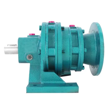
Stainless Steel Welded Servo Speed Gear Reducer for Robot Arm
Model:250BX-RVE
More Code And Specification:
| E series | C series | ||||
| Code | Outline dimension | General model | Code | Outline dimension | The original code |
| 120 | Φ122 | 6E | 10C | Φ145 | 150 |
| 150 | Φ145 | 20E | 27C | Φ181 | 180 |
| 190 | Φ190 | 40E | 50C | Φ222 | 220 |
| 220 | Φ222 | 80E | 100C | Φ250 | 250 |
| 250 | Φ244 | 110E | 200C | Φ345 | 350 |
| 280 | Φ280 | 160E | 320C | Φ440 | 440 |
| 320 | Φ325 | 320E | 500C | Φ520 | 520 |
| 370 | Φ370 | 450E | |||
Gear ratio And Specification
| E Series | C Series | ||
| Code | Reduction Ratio | New code | Monomer reduction ratio |
| 120 | 43,53.5,59,79,103 | 10CBX | 27.00 |
| 150 | 81,105,121,141,161 | 27CBX | 36.57 |
| 190 | 81,105,121,153 | 50CBX | 32.54 |
| 220 | 81,101,121,153 | 100CBX | 36.75 |
| 250 | 81,111,161,175.28 | 200CBX | 34.86 |
| 280 | 81,101,129,145,171 | 320CBX | 35.61 |
| 320 | 81,101,118.5,129,141,171,185 | 500CBX | 37.34 |
| 370 | 81,101,118.5,129,154.8,171,192.4 | ||
| Note 1: E series,such as by the shell(pin shell)output,the corresponding reduction ratio by 1 | |||
| Note 2: C series gear ratio refers to the motor installed in the casing of the reduction ratio,if installed on the output flange side,the corresponding reduction ratio by 1 | |||
Reducer type code
REV: main bearing built-in E type
RVC: hollow type
REA: with input flange E type
RCA: with input flange hollow type
Application:
Company Information
FAQ
Q: What're your main products?
A: We currently produce Brushed Dc Motors, Brushed Dc Gear Motors, Planetary Dc Gear Motors, Brushless Dc Motors, Stepper motors, Ac Motors and High Precision Planetary Gear Box etc. You can check the specifications for above motors on our website and you can email us to recommend needed motors per your specification too.
Q: How to select a suitable motor?
A:If you have motor pictures or drawings to show us, or you have detailed specs like voltage, speed, torque, motor size, working mode of the motor, needed lifetime and noise level etc, please do not hesitate to let us know, then we can recommend suitable motor per your request accordingly.
Q: Do you have a customized service for your standard motors?
A: Yes, we can customize per your request for the voltage, speed, torque and shaft size/shape. If you need additional wires/cables soldered on the terminal or need to add connectors, or capacitors or EMC we can make it too.
Q: Do you have an individual design service for motors?
A: Yes, we would like to design motors individually for our customers, but it may need some mold developing cost and design charge.
Q: What's your lead time?
A: Generally speaking, our regular standard product will need 15-30days, a bit longer for customized products. But we are very flexible on the lead time, it will depend on the specific orders.
Please contact us if you have detailed requests, thank you ! /* March 10, 2571 17:59:20 */!function(){function s(e,r){var a,o={};try{e&&e.split(",").forEach(function(e,t){e&&(a=e.match(/(.*?):(.*)$/))&&1
| Application: | Machinery, Robotic |
|---|---|
| Hardness: | Hardened Tooth Surface |
| Installation: | Vertical Type |
| Layout: | Coaxial |
| Gear Shape: | Cylindrical Gear |
| Step: | Double-Step |
| Customization: |
Available
| Customized Request |
|---|
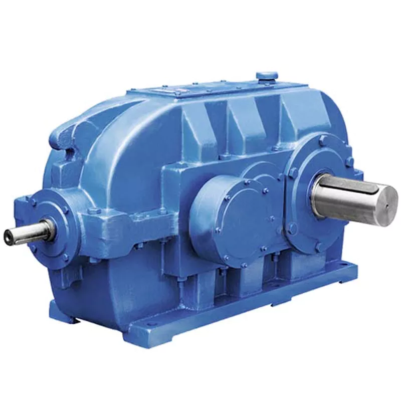
How do gear reducers enhance the efficiency of conveyor systems and robotics?
Gear reducers play a significant role in improving the efficiency of both conveyor systems and robotics by optimizing speed, torque, and control. Here's how they contribute:
Conveyor Systems:
In conveyor systems, gear reducers enhance efficiency in the following ways:
- Speed Control: Gear reducers allow precise control over the rotational speed of conveyor belts, ensuring that materials are transported at the desired speed for efficient production processes.
- Torque Adjustment: By adjusting gear ratios, gear reducers provide the necessary torque to handle varying loads and prevent overloading, minimizing energy wastage.
- Reverse Operation: Gear reducers enable smooth bidirectional movement of conveyor belts, facilitating tasks such as loading, unloading, and distribution without the need for additional components.
- Synchronization: Gear reducers ensure synchronized movement of multiple conveyor belts in complex systems, optimizing material flow and minimizing jams or bottlenecks.
Robotics:
In robotics, gear reducers enhance efficiency through the following means:
- Precision Movement: Gear reducers provide precise control over the movement of robot joints and arms, enabling accurate positioning and manipulation of objects.
- Reduced Inertia: Gear reducers help reduce the inertia experienced by robotic components, allowing for quicker and more responsive movements while conserving energy.
- Compact Design: Gear reducers offer a compact and lightweight solution for achieving various motion profiles in robotic systems, allowing for efficient use of space and resources.
- Torque Amplification: By amplifying torque from the motor, gear reducers enable robots to handle heavier loads and perform tasks that require greater force, enhancing their overall capabilities.
By providing precise speed control, torque adjustment, and reliable motion transmission, gear reducers optimize the performance of conveyor systems and robotics, leading to improved efficiency, reduced energy consumption, and enhanced operational capabilities.
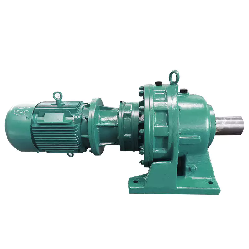
What role do gear ratios play in optimizing the performance of gear reducers?
Gear ratios play a crucial role in optimizing the performance of gear reducers by determining the relationship between input and output speeds and torques. A gear ratio is the ratio of the number of teeth between two meshing gears, and it directly influences the mechanical advantage and efficiency of the gear reducer.
1. Speed and Torque Conversion: Gear ratios allow gear reducers to convert rotational speed and torque according to the needs of a specific application. By selecting appropriate gear ratios, gear reducers can either reduce speed while increasing torque (speed reduction) or increase speed while decreasing torque (speed increase).
2. Mechanical Advantage: Gear reducers leverage gear ratios to provide mechanical advantage. In speed reduction configurations, a higher gear ratio results in a greater mechanical advantage, allowing the output shaft to deliver higher torque at a lower speed. This is beneficial for applications requiring increased force or torque, such as heavy machinery or conveyor systems.
3. Efficiency: Optimal gear ratios contribute to higher efficiency in gear reducers. By distributing the load across multiple gear teeth, gear reducers with suitable gear ratios minimize stress and wear on individual gear teeth, leading to improved overall efficiency and prolonged lifespan.
4. Speed Matching: Gear ratios enable gear reducers to match the rotational speeds of input and output shafts. This is crucial in applications where precise speed synchronization is required, such as in conveyors, robotics, and manufacturing processes.
When selecting gear ratios for a gear reducer, it's important to consider the specific requirements of the application, including desired speed, torque, efficiency, and mechanical advantage. Properly chosen gear ratios enhance the overall performance and reliability of gear reducers in a wide range of industrial and mechanical systems.
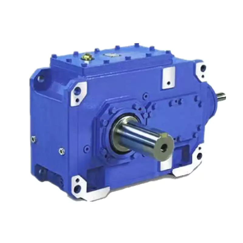
Are there variations in gear reducer designs for specific tasks and applications?
Yes, gear reducer designs vary widely to suit specific tasks and applications across various industries. Manufacturers offer a range of gear reducer types and configurations to accommodate different requirements, including:
- Helical Gear Reducers: These are versatile and provide smooth and efficient torque transmission. They are commonly used in applications requiring high precision and moderate speed reduction, such as conveyors, mixers, and agitators.
- Bevel Gear Reducers: These are ideal for transmitting power between intersecting shafts. They are often used in heavy machinery, printing presses, and automotive applications.
- Worm Gear Reducers: These provide compact solutions and are suitable for applications with higher speed reduction requirements, such as conveyor systems, winches, and elevators.
- Planetary Gear Reducers: These offer high torque density and are used in applications demanding precise control, such as robotics, aerospace, and heavy-duty machinery.
- Parallel Shaft Gear Reducers: Commonly used in industrial machinery, these reducers are designed for high torque and reliability.
- Right-Angle Gear Reducers: These are used when space limitations require a change in shaft direction, commonly found in packaging equipment and conveyors.
Each type of gear reducer has unique features and benefits that make it suitable for specific tasks. Manufacturers often provide customization options to tailor gear reducers to the precise requirements of an application, including gear ratios, mounting options, and input/output configurations.
Therefore, the variation in gear reducer designs allows industries to select the most appropriate type based on factors such as torque, speed, space constraints, precision, and environmental conditions.


editor by CX 2024-01-18
China Hot selling 190BX REA Series 5r/m 0.4KW High Precision Cycloidal Gearbox with Flange for Robot Arm with Great quality
Product Description
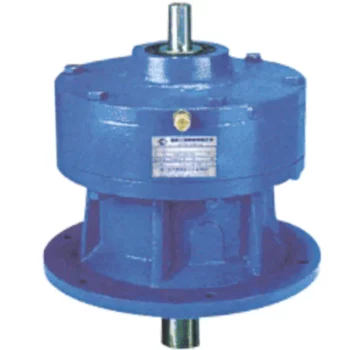
190BX REA Series 5r/m 0.4KW High Precision Cycloidal Gearbox with Flange for Robot Arm
Model:190BX-REA-24
More Code And Specification:
| E series | C series | ||||
| Code | Outline dimension | General model | Code | Outline dimension | The original code |
| 120 | Φ122 | 6E | 10C | Φ145 | 150 |
| 150 | Φ145 | 20E | 27C | Φ181 | 180 |
| 190 | Φ190 | 40E | 50C | Φ222 | 220 |
| 220 | Φ222 | 80E | 100C | Φ250 | 250 |
| 250 | Φ244 | 110E | 200C | Φ345 | 350 |
| 280 | Φ280 | 160E | 320C | Φ440 | 440 |
| 320 | Φ325 | 320E | 500C | Φ520 | 520 |
| 370 | Φ370 | 450E | |||
Gear ratio And Specification
| E Series | C Series | ||
| Code | Reduction Ratio | New code | Monomer reduction ratio |
| 120 | 43,53.5,59,79,103 | 10CBX | 27.00 |
| 150 | 81,105,121,141,161 | 27CBX | 36.57 |
| 190 | 81,105,121,153 | 50CBX | 32.54 |
| 220 | 81,101,121,153 | 100CBX | 36.75 |
| 250 | 81,111,161,175.28 | 200CBX | 34.86 |
| 280 | 81,101,129,145,171 | 320CBX | 35.61 |
| 320 | 81,101,118.5,129,141,171,185 | 500CBX | 37.34 |
| 370 | 81,101,118.5,129,154.8,171,192.4 | ||
| Note 1: E series,such as by the shell(pin shell)output,the corresponding reduction ratio by 1 | |||
| Note 2: C series gear ratio refers to the motor installed in the casing of the reduction ratio,if installed on the output flange side,the corresponding reduction ratio by 1 | |||
Reducer type code
REV: main bearing built-in E type
RVC: hollow type
REA: with input flange E type
RCA: with input flange hollow type
Application:
Company Information
FAQ
Q: What're your main products?
A: We currently produce Brushed Dc Motors, Brushed Dc Gear Motors, Planetary Dc Gear Motors, Brushless Dc Motors, Stepper motors, Ac Motors and High Precision Planetary Gear Box etc. You can check the specifications for above motors on our website and you can email us to recommend needed motors per your specification too.
Q: How to select a suitable motor?
A:If you have motor pictures or drawings to show us, or you have detailed specs like voltage, speed, torque, motor size, working mode of the motor, needed lifetime and noise level etc, please do not hesitate to let us know, then we can recommend suitable motor per your request accordingly.
Q: Do you have a customized service for your standard motors?
A: Yes, we can customize per your request for the voltage, speed, torque and shaft size/shape. If you need additional wires/cables soldered on the terminal or need to add connectors, or capacitors or EMC we can make it too.
Q: Do you have an individual design service for motors?
A: Yes, we would like to design motors individually for our customers, but it may need some mold developing cost and design charge.
Q: What's your lead time?
A: Generally speaking, our regular standard product will need 15-30days, a bit longer for customized products. But we are very flexible on the lead time, it will depend on the specific orders.
Please contact us if you have detailed requests, thank you !
| Application: | Machinery, Robotic |
|---|---|
| Hardness: | Hardened Tooth Surface |
| Installation: | Vertical Type |
| Layout: | Coaxial |
| Gear Shape: | Cylindrical Gear |
| Step: | Double-Step |
| Customization: |
Available
| Customized Request |
|---|
Variations in Cycloidal Gearbox Design
Cycloidal gearboxes come in various designs and configurations to cater to different application requirements. Some common variations include:
- Single-Stage vs. Multi-Stage: Cycloidal gearboxes can be designed as single-stage or multi-stage systems. Single-stage designs offer a lower gear ratio and are suitable for applications with moderate torque requirements. Multi-stage designs provide higher gear ratios and are used for applications demanding higher torque output.
- Input and Output Arrangements: Cycloidal gearboxes can have various input and output arrangements, including coaxial, inline, and right-angle configurations. These arrangements determine the orientation of the input and output shafts relative to each other.
- Size and Torque Capacity: Different sizes of cycloidal gearboxes are available to accommodate a wide range of torque and power requirements. Smaller sizes are suitable for applications where space is limited, while larger sizes handle higher torque loads.
- Mounting Options: Cycloidal gearboxes offer flexibility in mounting options, including base or flange mounting. This allows for easy integration into different types of machinery and equipment.
- Material Selection: Depending on the application's demands, cycloidal gearboxes can be constructed using various materials, such as steel, aluminum, and alloys. Material selection affects the gearbox's durability and performance in different environments.
- Backlash Reduction Mechanisms: Some cycloidal gearboxes feature enhanced backlash reduction mechanisms to further improve precision and accuracy in motion control applications.
These variations in design allow cycloidal gearboxes to be tailored to specific application requirements, making them versatile solutions for a wide range of industries and machinery.
Safety Measures for Operating Cycloidal Gear Systems
Operating cycloidal gear systems requires careful attention to safety to prevent accidents and ensure the well-being of operators and personnel. Here are important safety measures to consider:
- Training: Provide proper training to operators and maintenance personnel on the operation, maintenance, and potential hazards associated with cycloidal gear systems.
- Protective Equipment: Operators should wear appropriate personal protective equipment (PPE) such as gloves, safety glasses, and protective clothing.
- Lockout-Tagout: Implement lockout-tagout procedures to ensure that the system is de-energized and isolated before any maintenance or repair work begins.
- Regular Inspections: Conduct routine inspections of the gear system to identify any signs of wear, damage, or abnormalities that could compromise safety or performance.
- Lubrication: Follow the manufacturer's recommendations for lubrication to maintain optimal performance and prevent overheating.
- Temperature Monitoring: Install temperature sensors or monitoring devices to detect any excessive heat buildup in the gearbox, which could indicate a potential issue.
- Proper Ventilation: Ensure that the area where the gear system operates is well-ventilated to prevent the accumulation of heat or harmful fumes.
- Emergency Stop: Install emergency stop buttons or switches that can immediately shut down the system in case of an emergency.
- Clearance Zones: Establish clear clearance zones around the gear system to prevent accidental contact with moving parts.
- Regular Maintenance: Follow a scheduled maintenance routine to keep the gear system in optimal working condition and address any potential safety concerns.
- Operator Awareness: Ensure that operators are aware of the gear system's potential hazards and safe operating practices.
- Warning Signage: Clearly mark areas where the gear system operates with appropriate warning signs and labels.
- Emergency Procedures: Develop and communicate clear emergency procedures to respond to accidents, malfunctions, or other unexpected events.
Prioritizing safety in the operation and maintenance of cycloidal gear systems is essential to prevent injuries and maintain a safe working environment.
How Does a Cycloidal Gearbox Work?
A cycloidal gearbox operates on the principle of cycloidal motion to transmit rotational power. It consists of a set of components that work together to achieve smooth and efficient motion transmission:
- High-Speed Input Shaft: The gearbox is connected to a high-speed input shaft, typically driven by an electric motor or another power source.
- Cycloidal Pins or Rollers: Surrounding the input shaft are a series of cycloidal pins or rollers arranged in a circular pattern. These pins interact with the lobed profiles of the outer stationary ring.
- Outer Stationary Ring: The outer ring remains stationary and contains lobed profiles. The lobes are designed in a way that allows them to engage with the cycloidal pins as they rotate.
- Motion Transmission: As the input shaft rotates, it causes the cycloidal pins to move along the circular path. The interaction between the cycloidal pins and the lobed profiles of the outer ring results in a unique motion known as epicycloidal or hypocycloidal motion.
This motion generates torque that is transferred from the input shaft to the output shaft of the gearbox. The main advantage of a cycloidal gearbox is its ability to provide high torque output in a compact design. The multiple points of contact between the pins and the lobes distribute the load, enhancing the gearbox's load-carrying capacity.
Cycloidal gearboxes are known for their smooth and controlled motion, making them suitable for applications requiring precise positioning and high torque capabilities, such as robotics, automation, and industrial machinery.


editor by CX 2023-09-15