Tag Archives: tractor snow blower

China Good quality China Cheap 3 Point Snow Blower Equipment for Farm Tractor near me factory

Product Description

China SAMTRA!! Snow Machine Blower for farm tractors with COC
We are the Manufacturer!!
 

Product Description

Description:

1. The ideal implement for clearing snow safely and effeciently. Widely used in traffic lanes, sidewalks, yards, etc.   

2. Powered by the tractor, matched  from 20 to 120hp. 

3. Quality Assurance: SGS and factory audit.

4. Snow Blade is optional replaceable.
5. with PTO Pump System for front snow blower

Application:

CX Series Snow Blower on tractor is widely used in road, ground, warehouse etc, mainly in blowing away of snow, dust etc. It's high efficiency and easy operation win warm praise from customers.

Product Parameters


SNOW BLOWER
Model Tractor Front Mounted CX130 CX160 CX180 CX210
Model Rear 3-point Hitched CX130-R CX160-R CX180-R CX210-R
Model For Front 3-point Linkage CX130-XG CX160-XG CX180-XG CX210-XG
Model For Front End Loader CX130-TZ CX160-TZ CX180-TZ CX210-TZ
Matching Tractor (hp) 20~40 40~60 60~90 80~120
Model CX130 CX160 CX180 CX210
Blowing Width (mm) 1300 1600 1800 2100
Blowing Height (mm) 600 600 600 600
Number of Blades 4 4 4 4
Dia. of Fan (mm) 500 500 500 500
Dia. of Feeding Sprial (mm) 360 360 360 360
Power of Driven Motor (hp) 15 15 20 20
Adjustable Angle of Snow Outlet (°) 360° 360° 360° 360°
Adjustable Type of Outlet Direction Manual Adjustable(standard)   Electric Adjustable(option)
Weight (kg) 200~300 220~330 240~370 260~420

Detailed Photos

For Front End Loader with SSP Quick Hitch for North America Market:
 

For Front End Loader with Euro Quick Hitch for EU Market:
 

Packaging & Shipping


Our Advantages

1. ZheZheJiang nco Agricultural Equipment Technology Co., Ltd. is a state-owned holding company, which is subordinate to ZheJiang Academy of Agricultural Machinery Sciences date from 1959.
 
2. We design, test, build and sell Agricultural  Equipment and Tractor Attachments for Farming and Forestry dealer and personal user customers. 
 
3. Our products are Made in China and Exported to Asia, Europe, America, Australia with annual exports over 7000 sets for more than 12 years. 

1. Strong Technical Support:

More than 80 professional and technical personnels;
Top universities and institutes cooperator;
A subordinate to ZheJiang Agricultural Machinery Research Institute

2. Top Quality Assurance:

Strict control and selection of materials;
Completely self manufactured and installed;
Advanced equipments and first-class production technology;
Sound management system and solid economic strength

3. Advanced Testing Measures:

Exclusive R&D, testing center;
Capable of undertaking national research projects;
Exclusive professional platform

4. Sound after-sale system, sincere and all-aspect service

5. OEM service is acceptable, every products can be customized

Some Star Products of SAMTRA:

FAQ


Types of Ball Bearings

There are many types of Ball Bearings available on the market, but which 1 is best for your application? Here, we will discuss the differences between Angular contact, Single-row, High-carbon steel, and Ceramic ball bearings. These types of bearings also feature races, or a groove in the center of each. These races are important in keeping the balls contained within the cylinder. They also provide a groove-baed pathway.
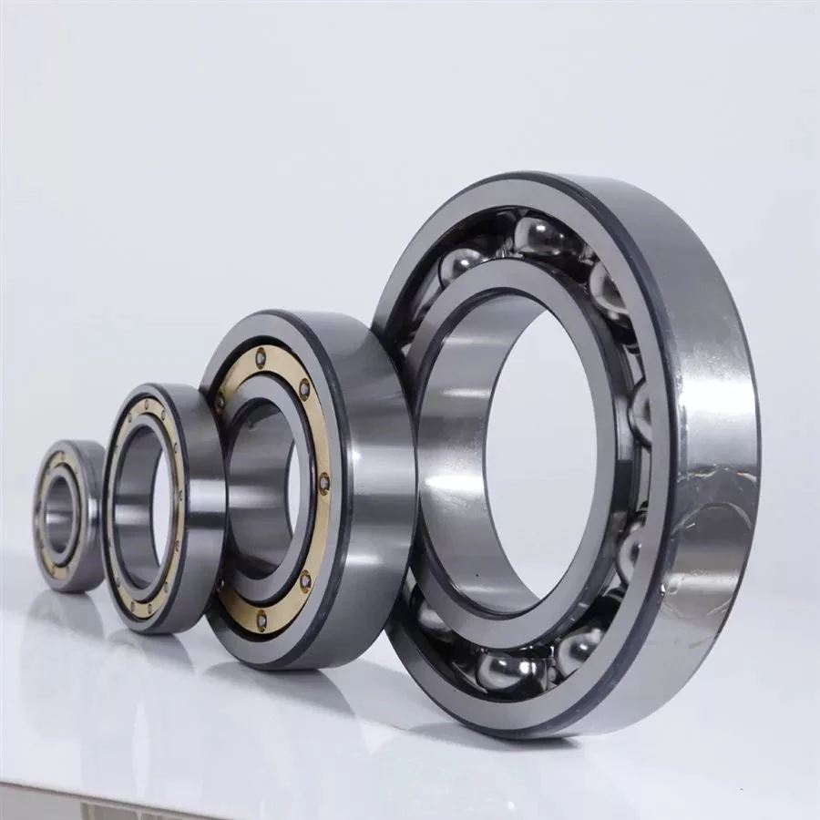
bearing

Ceramic

The ceramic ball used in ball bearings has many advantages. It is lightweight, operates at lower temperatures, has reduced skidding, and is resistant to electrolysis. The ball also exhibits longer fatigue life. All of these factors make the ceramic ball a good choice for many applications. But, how do you know if a ceramic ball bearing is right for your application? Read on to discover why ceramic ball bearings are a better choice than steel or stainless steel ones.
The ceramic balls are 40% more dense than steel. This means less centrifugal force is generated on the bearing, which suppresses heat generation. Because of this reduced friction, ceramic bearings are more efficient at transferring energy. Compared to steel bearings, ceramic balls have longer life spans. Nonetheless, these ceramic balls aren't as strong as steel. Therefore, it is important to understand the limitations of the ceramic ball bearing before buying one.
The ceramic materials used for ball bearings are resistant to micro-welding. Metals undergo this process when imperfections in the surfaces interact. Eventually, this results in a brittle ball that reduces the life of a bearing. Unlike metals, ceramic materials have a stable behavior at high temperatures and exhibit less thermal expansion. This means that they can be used for applications where lubrication isn't an option.
While steel balls can easily absorb contaminants and foreign particles, the ceramic ball is insensitive to this, and doesn't require lubrication. This means they're not susceptible to corrosion and other common problems. These are just a few reasons why ceramics are a better choice. This technology has a wide range of uses. It's easy to see why it is so popular. If you're looking for a new bearing for your application, be sure to contact an AST Applications Engineer. They can analyze your operating conditions and potential failure modes.

Angular contact

An Angular Contact Ball Bearing (also known as an angular-contact bearing) has an axial component that is generated when radial loads are applied. They are generally used in pairs, triplex sets, or quadruplex sets. These bearings are also available with Super Finished Raceways to reduce noise and improve lubricant distribution. Angular contact ball bearings have various design units, such as bore size, outer diameter, and outer ring width.
A single-row angular contact bearing has a radial contact angle that is equal to the angular distance between the 2 rings. Double-row angular bearings are designed for two-way thrust capability. These types of bearings can be purchased at Grainger and other online retailers. A typical angular contact bearing will last up to a million revolutions. They are often used in industrial angular contact bearings.
Single-row angular contact ball bearings feature a set contact angle. These bearings can support radial and axial loads, but they can't withstand high speeds. Single-row angular contact ball bearings may also have 1 or 2 shoulders relieved. Thrust load is a pressure placed on the bearing when it is installed in an assembly, and it is used to create an angle between the races.
Angular contact ball bearings come in single and double-row configurations. They differ in the axial load they can carry and the type of lubrication they use. Angular contact ball bearings are ideal for high-speed applications and can accommodate both radial and axial loads. The type of contact and lubrication used in angular-contact ball bearings depends on the intended use for the bearing.
bearing

High-carbon steel

Carbon steel is a low-alloy and high-carbon steel used in bearings. This material provides superior strength and fatigue properties for ball and roller bearings. Its mechanical properties are ideal for applications where the temperature is less than 400 degrees Fahrenheit. High-carbon steel is also used to make bearing components for chrome steel bearings. These types of steels are softer than chrome steel but provide superior durability in applications where the material is exposed to severe conditions.
Hardened carbon steel balls with an AISI 1015 hardness index are used in a variety of automotive, commercial, and semi-precision applications. In addition to automotive applications, they are also used in slides, trolleys, and conveyors. AISI 1015 carbon steel balls are used in bearings. They can be purchased in a variety of weights and diameters. Carbon steel balls can also be purchased in nickel-plated or uncoated varieties for decorative purposes.
In order to determine whether a ball bearing is made of high-carbon steel, the material must be tested for its hardness. An ordinary pocket magnet will work well, but an ordinary rare earth magnet isn't powerful enough to measure the hardness. If it attracts the magnet strongly, the metal is steel, while a weak magnet indicates a non-ferrous material. A hardness test requires a special microhardness test.
A lower-carbon steel is another option. Some miniature bearing manufacturers use a material with less carbon than AISI 440C. This material is also known as KS440 or X65Cr13. After being heat-treated, it develops smaller carbides, resulting in superior low-noise characteristics and the same corrosion-resistance as 440C. These materials are a less expensive alternative than chrome steel, but they are often less durable than chrome alloy steel.

Single-row

Single-row angular contact ball bearings accommodate axial loads in 1 direction. These are normally adjusted against a second bearing. Unlike other ball bearings, they are non-separable and contain an upper and lower shoulder. Single-row ball bearings are made of Chromium Steel (GCr15) which is heat-treated to achieve high uniform hardness and excellent wear resistance. They are the most commonly used type of bearings in the world.
Because of the angular contact between the radial plane and the raceway, single-row ball bearings transmit radial forces from raceway to raceway. A higher a, the greater the axial load carrying capacity of the bearing. Single-row angular contact ball bearings are ideal for high axial loads. However, they have limited preload capabilities and must be installed in pairs. Hence, they are best used for applications where axial forces must be distributed.
Single-row ball bearings can be pre-lubricated and have steel shields. They are also available with rubber seals or snap rings on the outside edge. They are available with various retainers, including pressed steel cages, plastic shields, and rubber seals. A tapered bore is also available upon request. They are ideal for applications where space is limited. The 6200 series of bearings are especially well suited for electrical motors, dental hand tools, and optical encoders.
Single-row angular contact ball bearings are widely used for axial loads. The outer and inner rings have slightly larger radii than the balls. These bearings can accommodate high speeds and low torque. They can also be supplied with different grease levels. If grease is needed, you can choose a lubricant that has different characteristics depending on the application. They are easy to install and maintain. However, they are not recommended for adjacent mounting.
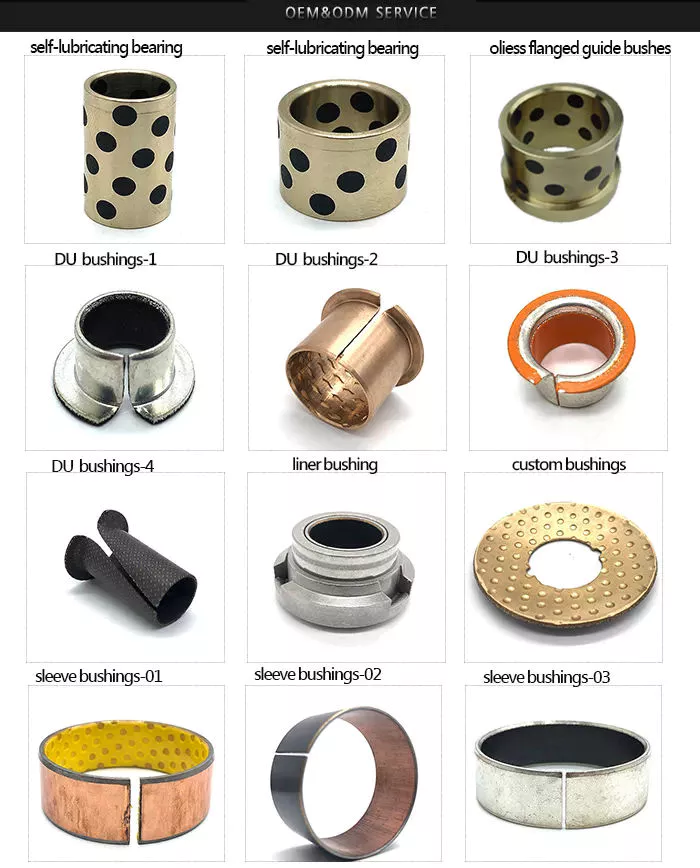
bearing

Plastic

A plastic ball bearing is a highly versatile component that can be mounted in a variety of components, including wheels, pulleys and housings. The outer ring of a plastic bearing is usually the pulley profile. The inner ring can be made of a shaft or polymer. The integrated design of a plastic ball bearing helps to reduce assembly time and cost. Here are some of the benefits of this type of bearing:
First and foremost, plastic balls are lighter than metal balls. They also have less magnetic properties than steel balls, making them the best option for applications requiring low weight and noise. Glass balls are also lighter than stainless steel balls, making them the ideal metal-free choice. They are also very corrosion-resistant, which makes them a great choice for some applications. In addition to being lightweight, polymer ball bearings are also quiet. And because of their low weight, plastic ball bearings are ideal for applications that require fast speed.
Another advantage of plastic bearings is their ability to withstand high temperatures. This material is also abrasion and corrosion-resistant. It meets FDA and USDA acceptance requirements. Aside from its abrasion-resistant and corrosion-resistant properties, these plastics do not transfer heat. Aside from being extremely durable and flexible, most plastics are also self-lubricating. Common plastics include phenolics, acetals, nylon, and ultra high molecular weight polyethylene. Nonetheless, plastics have limitations, and these materials may be damaged by extreme temperatures or cold flow under heavy loads.
Other advantages of plastic ball bearings include their low density, high hardness and low friction coefficient, and ability to withstand heat and corrosion. Ceramics are also lightweight, non-conductive, and have superior resistance to friction. These products can withstand temperatures up to 1,800 degrees Fahrenheit. If you're in the market for a plastic ball bearing, it's important to choose the right type of material. And if you're looking for a high-quality bearing, look no further.

China Good quality China Cheap 3 Point Snow Blower Equipment for Farm Tractor     near me factory China Good quality China Cheap 3 Point Snow Blower Equipment for Farm Tractor     near me factory

China Custom Three Point Hitch Snow Blower for Tractor with high quality

Product Description

Three point hitch snow blower for tractor

Product Description

Model SB160 SB180 FSB160 FSB180
Dimension(L*W*H) 1650x875x1345mm 1800*875*1345mm 1650x875x1345mm 1800*875*1345mm
Working Width 1600mm 1800mm 1600mm 1800mm
Weight 220kg 238kg 220kg 238kg
Power PTO PTO Hydraulic Hydraulic
Tractor HP 20-50 HP 30-40 HP 20-50 HP 30-40 HP

 Certification

FAQ 

01 Are you factory or trading company? 

A) We are ISO9001 certified factory, mainly manufacture in Forestry & Farm Machinery. 
B) Using "Self-produced Self-marketing" business, reducing the cost of intermediate links

02 Can we buy 1 sample? 

Yes, 1 sample order is welcome. However, we need to add sample fee to the price and will return it back after receiving your large order in future. 

03 What's your delivery time? 

After receiving payment, we start to produce your order. It usually takes about 15-45 days depending on the products you order. 

04 What's your product warranty? 

One year. During this period, we will send you the replacement for the broken part(not caused by wrong operation)

05 If I need different measurements or weight, could you offer OEM service? 

Sure, we can provide OEM service, also we can make new CZPT for your product, attaching your name brand. 

06 What's your advantages? 

With our 2 factories and more than 100 workers, we can offer you the following service: 

A. Very competitive advantage products! 
B. 7 days money refund in case of bad quality! 
C. Small order welcome! 
D. QC for each product before delivery
E. Nice after sale service. 

07 How do you control your quality? 

To guarantee high quality and efficient management, we have passed ISO9001 quality management system certificate. All of our products are 100% inspected before shipment. Our whole manufacturing processes are under a very serious and strict system in our company. 

Customer visit

Contact us


Bushing Application, Type and Compression Capability

Bushings are cylindrical bushings used in machinery. It prevents wear of moving parts and is often used as an enclosure. Bushings are also known as plain bearings or sleeve bearings. You may be wondering what these parts do and how they work, but this article aims to answer all your questions. We'll cover bushing applications, types and compression capabilities so you can choose the right 1 for your needs.
bushing

application

A bushing is a mechanical component that plays an important role in many different fields. In addition to being very practical, it helps reduce noise, vibration, wear and provides anti-corrosion properties. These properties help mechanical equipment in various ways, including making it easier to maintain and reducing its overall structure. The functionality of an enclosure depends on its purpose and environment. This article will discuss some of the most common applications of casing.
For example, in an aircraft, the bushing assembly 16 may be used for the bulkhead isolator 40 . The bushing assembly 16 provides the interfaces and paths required for current flow. In this manner, the sleeve assembly provides a secure, reliable connection between 2 objects with different electrical charges. They also prevent sparking by increasing the electrical conductivity of the component and reducing its resistivity, thereby minimizing the chance of spark formation.
Another common application for bushings is as a support shaft. Unlike bearings, bushings operate by sliding between 2 moving surfaces. As a result, they reduce friction and handling stress, reducing overall maintenance costs. Typically, the bushing is made of brass or bronze. The benefits of bushings are similar to those of bearings. They help extend the life of rotating machines by reducing frictional energy loss and wear.
In addition to identifying growth opportunities and minimizing risks, the Bushing Anti-Vibration Mounts Market report provides insights into the dynamics of the industry and its key players. The report covers global market size, applications, growth prospects, challenges and regional forecasts. The detailed section on Bushing Anti-Vibration Mounts industry provides insights on demand and supply along with competitive analysis at regional and country level.

type

There are several types of bushings. Among them, the SF6 insulating sleeve has the simplest structure and is based on composite hollow insulators. It also has several metal shielding cylinders for regulating the electric field within the enclosure and another for grounding the metal shield. In addition to being lightweight, this sleeve is also very durable, but the diameter of its shield electrode is very large, which means special installation and handling procedures are required.
Linear bushings are usually pressed into the bore of the shaft and provide support as the shaft moves in/out. Non-press-fit bushings are held in place by snap rings or pins. For certain applications, engineers often choose bushings over bearings and vice versa. That's why. Below are some common bushing types. If you need to buy, make sure you know how to tell them apart.
OIP bushings are used for oil-filled cable boxes, and oil-to-oil bushings are used for EHV power transformers. The main components of the OIP enclosure are shown in Figure 7a. If you are considering this type of bushing for your specific application, you need to make sure you understand your specific requirements. You can also consult your local engineering department for more information.
All types of bushings should be tested for IR and capacitance. The test tap should be securely attached to the bushing flange. If damaged bushings are found, replace them immediately. Be sure to keep complete records of the enclosure for routine maintenance and any IR testing. Also, be sure to pay attention to tan d and thermal vision measurements.
bushing

Compressive ability

There are several things to consider when choosing an enclosure. First, the material. There are 2 main types of bushings: those made of filled Teflon and those made of polyester resin. The former has the highest compressive strength, while the latter has a lower compressive capacity. If you need small amounts, glass-filled nylon bushings are the most common and best option. Glass-filled nylon is an economical material with a compressive strength of 36,000 lbs.
Second, the material used for the enclosure must be able to withstand the load. For example, bronze bushings can cause metal shavings to fall into the papermaking process. CG materials can withstand very high levels of moisture, which can damage bushings that require lubrication. Additionally, these materials can operate for extended periods of time without lubrication. This is particularly advantageous in the paper industry, since the casing operates in a humid environment.
In addition to the material and its composition, other characteristics of the enclosure must also be considered, including its operating temperature. Although frictional heat from moving loads and the temperature of the bushing itself can affect the performance of the bushing, these factors determine its service life. For high temperature applications, the PV of the enclosure should be kept low. On the other hand, plastic bushings are generally less heat resistant than metal bushings. In addition, plastic sleeves have a high rate of thermal expansion. To avoid this, size control is also important.
Low pressure bushings have different requirements. An 800 MVA installation requires a low voltage bushing rated at 14 000 A. The palm assembly of the transformer also features a large central copper cylinder for electrical current. The bushing must withstand this amount of current and must maintain an even distribution of current in the transformer tank. If there is a leak, the bushing must be able to resist the leak so as not to damage the transformer.

cost

The cost of new control arm bushings varies widely. Some parts are cheaper than others, and a new part is only $200. However, if you replace the 4 control bushings in your car, the cost can exceed $1,200. The cost breakdown for each section is listed below. If you plan to replace all four, the cost of each bushing may range from $200 to $500.
The control arm bushing bears the brunt of the forces generated by the tire and is parallel to the direction of the force. However, over time, these components wear out and need to be replaced. Replacing 1 control arm bushing costs between $300 and $1,200. However, the cost of replacing each arm bushing depends on your car model and driving habits. The control arm bushings should last about 100,000 miles before needing replacement.
The repair process for control arm bushings is time consuming and expensive. Also, they may need to remove the heat shield or bracket. In either case, the procedure is simple. Stabilizer bar brackets are usually attached with 1 or 2 mounting bolts. They can also be secured with nuts or threaded holes. All you need is a wrench to remove them.
The control arm bushings are made of 2 metal cylinders and a thick rubber bushing. These parts can deteriorate from potholes, off-roading or accidents. Because they are made of rubber, the parts are more expensive than new. Buying used ones can save you money because you don't need to install them yourself. However, if you do plan on fixing a luxury car yourself, be sure to find 1 that has a warranty and warranty.
bushing

maintain

To prevent your vehicle from overheating and leaking oil, a properly functioning bushing must be used. If the oil level is too low, you will need to check the mounting bolts to make sure they are properly tightened. Check gasket to ensure proper compression is applied, replace bushing if necessary. You should notify your vehicle manufacturer if your vehicle is immersed in oil. Whenever an oil leak occurs, it is very important to replace the oil-filled bushing.
Another important aspect of bushing maintenance is the detection and correction of partial discharges. Partial discharge is caused by current entering the bushing. Partial discharge can cause tree-like structures, cracks and carbonization in the discharge channel, which can eventually damage the casing. Early detection of these processes is critical to ensuring that your vehicle's bushings are properly maintained. Identifying and repairing partial discharges is critical to ensuring optimal operation, regardless of the type of pump or motor.
To diagnose casing condition, perform several tests. You can use tan d measurement, which is a powerful tool for detecting the ingress of water and moisture. You can also use power factor measurements to detect localized defects and aging effects. You can also check the oil level by performing an infrared check. After completing these tests, you will be able to determine if there is enough oil in the casing.
If the oil level in the transformer is too low, water and air may leak into the transformer. To avoid this problem, be sure to check the MOG and transformer oil levels. If the silicone is pink, replace it. You should also check the function of the oil pump, fan and control circuits annually. Check the physical condition of the pump and fan and whether they need to be replaced. Clean the transformer bushing with a soft cotton cloth and inspect for cracks.

China Custom Three Point Hitch Snow Blower for Tractor     with high qualityChina Custom Three Point Hitch Snow Blower for Tractor     with high quality

China OEM DQ904 Tractor with Pallet Fork, 4in1 Loader, Slasher Mower, Post Hole Digger, Hay Baler, Box Blade, Snow Blower etc.90HP, 4WD near me factory

Product Description

90HP,; 4WD Drive,; Big Tractors,; Agriculture Tractor,; Wheeled Tractor,; OEM Tractor,; Luxury Cabin With A/C Can Fit With Plough,; Harrow,; Loader,; Mower,; Tipping Trailer etc.;

The tractor can fit with attachments like:; 4in1 front end loader,; backhoe,; slasher mower,; flail mower,; CZPT mower,; wood chipper,; disc plough,; share plough,; disc harrow,; trailer,; rotary tiller,; grader blade,; seeder,; carry all,; post hole digger,; snow blower,; snow blade etc.;

Front end loader TZ06D,; this type is All quick-link and with flat rise and lower,; triple linkage control,; add 4in1 bucket,; pallet fork.;

Backhoe(excavator); LW-8,; PTO driven,; self hydraulic pump,; oil tank,; increasing speed gear box,; handed control valve,; luxury spring seat,; safety belt.;

Please contact us for more details.;

  Model TZ03D TZ04D TZ06D TZ08D
  Tractor model 254/284/304/354 404/454/504/554 604/654/704 754/804/854/904
A Height–measured at arm pivot point 2700 2800 3100 3080
C Max. dump height (mm) 2000 2100 2300 2350
D Dump distance (Max. dump height) (mm) 800 900 1100 1100
E Dump angle ( ° ) (Max. dump height) (mm) 45 45 45 43
F Distance to the centre of front-wheel (mm) 1900 1900 2300 2400
G Rollback angle on ground ( ° ) 32 32 34 34
H Max. CZPT depth (mm) 140 140 140 180
  Bucket width (mm) 1400 1500 1600 1700
  Bucket capacity (m 3 ) 0.21 0.23 0.43 0.46
  Rated lift capacity (Kg) 350 600 700 1000
Model LW-6 LW-7 LW-8
Tractor model 254/284/304/354 404/454/504/554/604/654 704/754/804/854/904
L1 (mm) 495 495 500
L2 ( pin of the boom distance) (mm) 517 540 632
φ 1(diameter of up hang pin  hole) (mm) 20 20 26
φ 2 ( diameter of down hang pin hole ) (mm) 20 23 29
A Max CZPT depth(mm) 1700 2100 2600
B dump height (mm) 1700 2300 2500
C Max CZPT height(mm) 2700 3300 3400
E height of arm pin to ground(mm) 430 430 450
F  Max CZPT depth in level base (mm) 1600 2000 2500
Dump angle ( ° ) 42° 42° 42°
Bucket width ( mm ) 340 380 420
Rated lift capacity (m3) 0.03 m 3 0.048 m 3 0.06 m 3

Analytical Approaches to Estimating Contact Pressures in Spline Couplings

A spline coupling is a type of mechanical connection between 2 rotating shafts. It consists of 2 parts - a coupler and a coupling. Both parts have teeth which engage and transfer loads. However, spline couplings are typically over-dimensioned, which makes them susceptible to fatigue and static behavior. Wear phenomena can also cause the coupling to fail. For this reason, proper spline coupling design is essential for achieving optimum performance.
splineshaft

Modeling a spline coupling

Spline couplings are becoming increasingly popular in the aerospace industry, but they operate in a slightly misaligned state, causing both vibrations and damage to the contact surfaces. To solve this problem, this article offers analytical approaches for estimating the contact pressures in a spline coupling. Specifically, this article compares analytical approaches with pure numerical approaches to demonstrate the benefits of an analytical approach.
To model a spline coupling, first you create the knowledge base for the spline coupling. The knowledge base includes a large number of possible specification values, which are related to each other. If you modify 1 specification, it may lead to a warning for violating another. To make the design valid, you must create a spline coupling model that meets the specified specification values.
After you have modeled the geometry, you must enter the contact pressures of the 2 spline couplings. Then, you need to determine the position of the pitch circle of the spline. In Figure 2, the centre of the male coupling is superposed to that of the female spline. Then, you need to make sure that the alignment meshing distance of the 2 splines is the same.
Once you have the data you need to create a spline coupling model, you can begin by entering the specifications for the interface design. Once you have this data, you need to choose whether to optimize the internal spline or the external spline. You'll also need to specify the tooth friction coefficient, which is used to determine the stresses in the spline coupling model 20. You should also enter the pilot clearance, which is the clearance between the tip 186 of a tooth 32 on 1 spline and the feature on the mating spline.
After you have entered the desired specifications for the external spline, you can enter the parameters for the internal spline. For example, you can enter the outer diameter limit 154 of the major snap 54 and the minor snap 56 of the internal spline. The values of these parameters are displayed in color-coded boxes on the Spline Inputs and Configuration GUI screen 80. Once the parameters are entered, you'll be presented with a geometric representation of the spline coupling model 20.

Creating a spline coupling model 20

The spline coupling model 20 is created by a product model software program 10. The software validates the spline coupling model against a knowledge base of configuration-dependent specification constraints and relationships. This report is then input to the ANSYS stress analyzer program. It lists the spline coupling model 20's geometric configurations and specification values for each feature. The spline coupling model 20 is automatically recreated every time the configuration or performance specifications of the spline coupling model 20 are modified.
The spline coupling model 20 can be configured using the product model software program 10. A user specifies the axial length of the spline stack, which may be zero, or a fixed length. The user also enters a radial mating face 148, if any, and selects a pilot clearance specification value of 14.5 degrees or 30 degrees.
A user can then use the mouse 110 to modify the spline coupling model 20. The spline coupling knowledge base contains a large number of possible specification values and the spline coupling design rule. If the user tries to change a spline coupling model, the model will show a warning about a violation of another specification. In some cases, the modification may invalidate the design.
In the spline coupling model 20, the user enters additional performance requirement specifications. The user chooses the locations where maximum torque is transferred for the internal and external splines 38 and 40. The maximum torque transfer location is determined by the attachment configuration of the hardware to the shafts. Once this is selected, the user can click "Next" to save the model. A preview of the spline coupling model 20 is displayed.
The model 20 is a representation of a spline coupling. The spline specifications are entered in the order and arrangement as specified on the spline coupling model 20 GUI screen. Once the spline coupling specifications are entered, the product model software program 10 will incorporate them into the spline coupling model 20. This is the last step in spline coupling model creation.
splineshaft

Analysing a spline coupling model 20

An analysis of a spline coupling model consists of inputting its configuration and performance specifications. These specifications may be generated from another computer program. The product model software program 10 then uses its internal knowledge base of configuration dependent specification relationships and constraints to create a valid three-dimensional parametric model 20. This model contains information describing the number and types of spline teeth 32, snaps 34, and shoulder 36.
When you are analysing a spline coupling, the software program 10 will include default values for various specifications. The spline coupling model 20 comprises an internal spline 38 and an external spline 40. Each of the splines includes its own set of parameters, such as its depth, width, length, and radii. The external spline 40 will also contain its own set of parameters, such as its orientation.
Upon selecting these parameters, the software program will perform various analyses on the spline coupling model 20. The software program 10 calculates the nominal and maximal tooth bearing stresses and fatigue life of a spline coupling. It will also determine the difference in torsional windup between an internal and an external spline. The output file from the analysis will be a report file containing model configuration and specification data. The output file may also be used by other computer programs for further analysis.
Once these parameters are set, the user enters the design criteria for the spline coupling model 20. In this step, the user specifies the locations of maximum torque transfer for both the external and internal spline 38. The maximum torque transfer location depends on the configuration of the hardware attached to the shafts. The user may enter up to 4 different performance requirement specifications for each spline.
The results of the analysis show that there are 2 phases of spline coupling. The first phase shows a large increase in stress and vibration. The second phase shows a decline in both stress and vibration levels. The third stage shows a constant meshing force between 300N and 320N. This behavior continues for a longer period of time, until the final stage engages with the surface.
splineshaft

Misalignment of a spline coupling

A study aimed to investigate the position of the resultant contact force in a spline coupling engaging teeth under a steady torque and rotating misalignment. The study used numerical methods based on Finite Element Method (FEM) models. It produced numerical results for nominal conditions and parallel offset misalignment. The study considered 2 levels of misalignment - 0.02 mm and 0.08 mm - with different loading levels.
The results showed that the misalignment between the splines and rotors causes a change in the meshing force of the spline-rotor coupling system. Its dynamics is governed by the meshing force of splines. The meshing force of a misaligned spline coupling is related to the rotor-spline coupling system parameters, the transmitting torque, and the dynamic vibration displacement.
Despite the lack of precise measurements, the misalignment of splines is a common problem. This problem is compounded by the fact that splines usually feature backlash. This backlash is the result of the misaligned spline. The authors analyzed several splines, varying pitch diameters, and length/diameter ratios.
A spline coupling is a two-dimensional mechanical system, which has positive backlash. The spline coupling is comprised of a hub and shaft, and has tip-to-root clearances that are larger than the backlash. A form-clearance is sufficient to prevent tip-to-root fillet contact. The torque on the splines is transmitted via friction.
When a spline coupling is misaligned, a torque-biased thrust force is generated. In such a situation, the force can exceed the torque, causing the component to lose its alignment. The two-way transmission of torque and thrust is modeled analytically in the present study. The analytical approach provides solutions that can be integrated into the design process. So, the next time you are faced with a misaligned spline coupling problem, make sure to use an analytical approach!
In this study, the spline coupling is analyzed under nominal conditions without a parallel offset misalignment. The stiffness values obtained are the percentage difference between the nominal pitch diameter and load application diameter. Moreover, the maximum percentage difference in the measured pitch diameter is 1.60% under a torque of 5000 N*m. The other parameter, the pitch angle, is taken into consideration in the calculation.

China OEM DQ904 Tractor with Pallet Fork, 4in1 Loader, Slasher Mower, Post Hole Digger, Hay Baler, Box Blade, Snow Blower etc.90HP, 4WD     near me factory China OEM DQ904 Tractor with Pallet Fork, 4in1 Loader, Slasher Mower, Post Hole Digger, Hay Baler, Box Blade, Snow Blower etc.90HP, 4WD     near me factory

China manufacturer Bubble Leaf Blower and Vacuum Tractor Mounted Large Cleaner Garden Leaves for with Snow 3 Point Hitch Snow Blower with Hot selling

Product Description

Product Name

Backpack Blower

Model NO.

EB9900

Engine:

4-stroke air cooled,,Single cylinder Gasoline

Max Power

2.2kw/6500rpm

Fuel tank capacity

0.9L

Fuel &Oil(2T) mix ratio

25:1

Start method

Recoil starter

Displacement

75.6cc

Packing size(L*W*H)

520x400x540mm

PCS/Container(set)

253pcs/20''      610pcs/40hp

N.W/G.W

10/12KG

Hypoid Bevel Vs Straight Spiral Bevel - What's the Difference?

Spiral gears come in many different varieties, but there is a fundamental difference between a Hypoid bevel gear and a Straight spiral bevel. This article will describe the differences between the 2 types of gears and discuss their use. Whether the gears are used in industrial applications or at home, it is vital to understand what each type does and why it is important. Ultimately, your final product will depend on these differences.
Gear

Hypoid bevel gears

In automotive use, hypoid bevel gears are used in the differential, which allows the wheels to rotate at different speeds while maintaining the vehicle's handling. This gearbox assembly consists of a ring gear and pinion mounted on a carrier with other bevel gears. These gears are also widely used in heavy equipment, auxiliary units, and the aviation industry. Listed below are some common applications of hypoid bevel gears.
For automotive applications, hypoid gears are commonly used in rear axles, especially on large trucks. Their distinctive shape allows the driveshaft to be located deeper in the vehicle, thus lowering the center of gravity and minimizing interior disruption. This design makes the hypoid gearset 1 of the most efficient types of gearboxes on the market. In addition to their superior efficiency, hypoid gears are very easy to maintain, as their mesh is based on sliding action.
The face-hobbed hypoid gears have a characteristic epicycloidal lead curve along their lengthwise axis. The most common grinding method for hypoid gears is the Semi-Completing process, which uses a cup-shaped grinding wheel to replace the lead curve with a circular arc. However, this method has a significant drawback - it produces non-uniform stock removal. Furthermore, the grinding wheel cannot finish all the surface of the tooth.
The advantages of a hypoid gear over a spiral bevel gear include a higher contact ratio and a higher transmission torque. These gears are primarily used in automobile drive systems, where the ratio of a single pair of hypoid gears is the highest. The hypoid gear can be heat-treated to increase durability and reduce friction, making it an ideal choice for applications where speed and efficiency are critical.
The same technique used in spiral bevel gears can also be used for hypoid bevel gears. This machining technique involves two-cut roughing followed by one-cut finishing. The pitch diameter of hypoid gears is up to 2500 mm. It is possible to combine the roughing and finishing operations using the same cutter, but the two-cut machining process is recommended for hypoid gears.
The advantages of hypoid gearing over spiral bevel gears are primarily based on precision. Using a hypoid gear with only 3 arc minutes of backlash is more efficient than a spiral bevel gear that requires 6 arc minutes of backlash. This makes hypoid gears a more viable choice in the motion control market. However, some people may argue that hypoid gears are not practical for automobile assemblies.
Hypoid gears have a unique shape - a cone that has teeth that are not parallel. Their pitch surface consists of 2 surfaces - a conical surface and a line-contacting surface of revolution. An inscribed cone is a common substitute for the line-contact surface of hypoid bevel gears, and it features point-contacts instead of lines. Developed in the early 1920s, hypoid bevel gears are still used in heavy truck drive trains. As they grow in popularity, they are also seeing increasing use in the industrial power transmission and motion control industries.
Gear

Straight spiral bevel gears

There are many differences between spiral bevel gears and the traditional, non-spiral types. Spiral bevel gears are always crowned and never conjugated, which limits the distribution of contact stress. The helical shape of the bevel gear is also a factor of design, as is its length. The helical shape has a large number of advantages, however. Listed below are a few of them.
Spiral bevel gears are generally available in pitches ranging from 1.5 to 2500 mm. They are highly efficient and are also available in a wide range of tooth and module combinations. Spiral bevel gears are extremely accurate and durable, and have low helix angles. These properties make them excellent for precision applications. However, some gears are not suitable for all applications. Therefore, you should consider the type of bevel gear you need before purchasing.
Compared to helical gears, straight bevel gears are easier to manufacture. The earliest method used to manufacture these gears was the use of a planer with an indexing head. However, with the development of modern manufacturing processes such as the Revacycle and Coniflex systems, manufacturers have been able to produce these gears more efficiently. Some of these gears are used in windup alarm clocks, washing machines, and screwdrivers. However, they are particularly noisy and are not suitable for automobile use.
A straight bevel gear is the most common type of bevel gear, while a spiral bevel gear has concave teeth. This curved design produces a greater amount of torque and axial thrust than a straight bevel gear. Straight teeth can increase the risk of breaking and overheating equipment and are more prone to breakage. Spiral bevel gears are also more durable and last longer than helical gears.
Spiral and hypoid bevel gears are used for applications with high peripheral speeds and require very low friction. They are recommended for applications where noise levels are essential. Hypoid gears are suitable for applications where they can transmit high torque, although the helical-spiral design is less effective for braking. For this reason, spiral bevel gears and hypoids are generally more expensive. If you are planning to buy a new gear, it is important to know which 1 will be suitable for the application.
Spiral bevel gears are more expensive than standard bevel gears, and their design is more complex than that of the spiral bevel gear. However, they have the advantage of being simpler to manufacture and are less likely to produce excessive noise and vibration. They also have less teeth to grind, which means that they are not as noisy as the spiral bevel gears. The main benefit of this design is their simplicity, as they can be produced in pairs, which saves money and time.
In most applications, spiral bevel gears have advantages over their straight counterparts. They provide more evenly distributed tooth loads and carry more load without surface fatigue. The spiral angle of the teeth also affects thrust loading. It is possible to make a straight spiral bevel gear with 2 helical axes, but the difference is the amount of thrust that is applied to each individual tooth. In addition to being stronger, the spiral angle provides the same efficiency as the straight spiral gear.
Gear

Hypoid gears

The primary application of hypoid gearboxes is in the automotive industry. They are typically found on the rear axles of passenger cars. The name is derived from the left-hand spiral angle of the pinion and the right-hand spiral angle of the crown. Hypoid gears also benefit from an offset center of gravity, which reduces the interior space of cars. Hypoid gears are also used in heavy trucks and buses, where they can improve fuel efficiency.
The hypoid and spiral bevel gears can be produced by face-hobbing, a process that produces highly accurate and smooth-surfaced parts. This process enables precise flank surfaces and pre-designed ease-off topographies. These processes also enhance the mechanical resistance of the gears by 15 to 20%. Additionally, they can reduce noise and improve mechanical efficiency. In commercial applications, hypoid gears are ideal for ensuring quiet operation.
Conjugated design enables the production of hypoid gearsets with length or profile crowning. Its characteristic makes the gearset insensitive to inaccuracies in the gear housing and load deflections. In addition, crowning allows the manufacturer to adjust the operating displacements to achieve the desired results. These advantages make hypoid gear sets a desirable option for many industries. So, what are the advantages of hypoid gears in spiral gears?
The design of a hypoid gear is similar to that of a conventional bevel gear. Its pitch surfaces are hyperbolic, rather than conical, and the teeth are helical. This configuration also allows the pinion to be larger than an equivalent bevel pinion. The overall design of the hypoid gear allows for large diameter shafts and a large pinion. It can be considered a cross between a bevel gear and a worm drive.
In passenger vehicles, hypoid gears are almost universal. Their smoother operation, increased pinion strength, and reduced weight make them a desirable choice for many vehicle applications. And, a lower vehicle body also lowers the vehicle's body. These advantages made all major car manufacturers convert to hypoid drive axles. It is worth noting that they are less efficient than their bevel gear counterparts.
The most basic design characteristic of a hypoid gear is that it carries out line contact in the entire area of engagement. In other words, if a pinion and a ring gear rotate with an angular increment, line contact is maintained throughout their entire engagement area. The resulting transmission ratio is equal to the angular increments of the pinion and ring gear. Therefore, hypoid gears are also known as helical gears.

China manufacturer Bubble Leaf Blower and Vacuum Tractor Mounted Large Cleaner Garden Leaves for with Snow 3 Point Hitch Snow Blower     with Hot sellingChina manufacturer Bubble Leaf Blower and Vacuum Tractor Mounted Large Cleaner Garden Leaves for with Snow 3 Point Hitch Snow Blower     with Hot selling

China high quality 3 Stage Snow Blower Tractor with Point Hitch Blowers Leaf Vacuum Heavy Duty Garden Motor Machine Pet Blower Dryer near me manufacturer

Product Description

Product Name

Backpack Blower

Model NO.

EB8890

Engine:

2-stroke air cooled,,Single cylinder Gasoline

Max Power

3.1kw/7000rpm

Carburetor

Diaphragm

Fuel &Oil(2T) mix ratio

25:1

Start method

Recoil starter

Displacement

75.6cc

Packing size(L*W*H)

550x420x585mm

PCS/Container(set)

210pcs/20''      505pcs/40hp

N.W/G.W

10.2/13KG

Types of Screw Shafts

Screw shafts come in various types and sizes. These types include fully threaded, Lead, and Acme screws. Let's explore these types in more detail. What type of screw shaft do you need? Which 1 is the best choice for your project? Here are some tips to choose the right screw:

Machined screw shaft

The screw shaft is a basic piece of machinery, but it can be further customized depending on the needs of the customer. Its features include high-precision threads and ridges. Machined screw shafts are generally manufactured using high-precision CNC machines or lathes. The types of screw shafts available vary in shape, size, and material. Different materials are suitable for different applications. This article will provide you with some examples of different types of screw shafts.
Ball screws are used for a variety of applications, including mounting machines, liquid crystal devices, measuring devices, and food and medical equipment. Various shapes are available, including miniature ball screws and nut brackets. They are also available without keyway. These components form a high-accuracy feed mechanism. Machined screw shafts are also available with various types of threaded ends for ease of assembly. The screw shaft is an integral part of linear motion systems.
When you need a machined screw shaft, you need to know the size of the threads. For smaller machine screws, you will need a mating part. For smaller screw sizes, the numbers will be denominated as industry Numeric Sizes. These denominations are not metric, but rather in mm, and they may not have a threads-per-inch designation. Similarly, larger machine screws will usually have threads that have a higher pitch than those with a lower pitch.
Another important feature of machine screws is that they have a thread on the entire shaft, unlike their normal counterparts. These machine screws have finer threads and are intended to be screwed into existing tapped holes using a nut. This means that these screws are generally stronger than other fasteners. They are usually used to hold together electronic components, industrial equipment, and engines. In addition to this, machine screws are usually made of a variety of materials.
screwshaft

Acme screw

An Acme screw is the most common type of threaded shaft available. It is available in a variety of materials including stainless steel and carbon steel. In many applications, it is used for large plates in crushing processes. ACME screws are self-locking and are ideal for applications requiring high clamping force and low friction. They also feature a variety of standard thread forms, including knurling and rolled worms.
Acme screws are available in a wide range of sizes, from 1/8" to 6". The diameter is measured from the outside of the screw to the bottom of the thread. The pitch is equal to the lead in a single start screw. The lead is equal to the pitch plus the number of starts. A screw of either type has a standard pitch and a lead. Acme screws are manufactured to be accurate and durable. They are also widely available in a wide range of materials and can be customized to fit your needs.
Another type of Acme screw is the ball screw. These have no back drive and are widely used in many applications. Aside from being lightweight, they are also able to move at faster speeds. A ball screw is similar to an Acme screw, but has a different shape. A ball screw is usually longer than an Acme screw. The ball screw is used for applications that require high linear speeds. An Acme screw is a common choice for many industries.
There are many factors that affect the speed and resolution of linear motion systems. For example, the nut position and the distance the screw travels can all affect the resolution. The total length of travel, the speed, and the duty cycle are all important. The lead size will affect the maximum linear speed and force output. If the screw is long, the greater the lead size, the higher the resolution. If the lead length is short, this may not be the most efficient option.
screwshaft

Lead screw

A lead screw is a threaded mechanical device. A lead screw consists of a cylindrical shaft, which includes a shallow thread portion and a tightly wound spring wire. This spring wire forms smooth, hard-spaced thread convolutions and provides wear-resistant engagement with the nut member. The wire's leading and trailing ends are anchored to the shaft by means appropriate to the shaft's composition. The screw is preferably made of stainless steel.
When selecting a lead screw, 1 should first determine its critical speed. The critical speed is the maximum rotations per minute based on the natural frequency of the screw. Excessive backlash will damage the lead screw. The maximum number of revolutions per minute depends on the screw's minor diameter, length, assembly alignment, and end fixity. Ideally, the critical speed is 80% of its evaluated critical speed. A critical speed is not exceeded because excessive backlash would damage the lead screw and may be detrimental to the screw's performance.
The PV curve defines the safe operating limits of a lead screw. This relationship describes the inverse relationship between contact surface pressure and sliding velocity. As the PV value increases, a lower rotation speed is required for heavier axial loads. Moreover, PV is affected by material and lubrication conditions. Besides, end fixity, which refers to the way the lead screw is supported, also affects its critical speed. Fixed-fixed and free end fixity are both possible.
Lead screws are widely used in industries and everyday appliances. In fact, they are used in robotics, lifting equipment, and industrial machinery. High-precision lead screws are widely used in the fields of engraving, fluid handling, data storage, and rapid prototyping. Moreover, they are also used in 3D printing and rapid prototyping. Lastly, lead screws are used in a wide range of applications, from measuring to assembly.

Fully threaded screw

A fully threaded screw shaft can be found in many applications. Threading is an important feature of screw systems and components. Screws with threaded shafts are often used to fix pieces of machinery together. Having fully threaded screw shafts ensures that screws can be installed without removing the nut or shaft. There are 2 major types of screw threads: coarse and fine. When it comes to coarse threads, UTS is the most common type, followed by BSP.
In the 1840s, a British engineer named Joseph Whitworth created a design that was widely used for screw threads. This design later became the British Standard Whitworth. This standard was used for screw threads in the United States during the 1840s and 1860s. But as screw threads evolved and international standards were established, this system remained largely unaltered. A new design proposed in 1864 by William Sellers improved upon Whitworth's screw threads and simplified the pitch and surface finish.
Another reason for using fully threaded screws is their ability to reduce heat. When screw shafts are partially threaded, the bone grows up to the screw shaft and causes the cavity to be too narrow to remove it. Consequently, the screw is not capable of backing out. Therefore, fully threaded screws are the preferred choice for inter-fragmentary compression in children's fractures. However, surgeons should know the potential complication when removing metalwork.
The full thread depth of a fully threaded screw is the distance at which a male thread can freely thread into the shaft. This dimension is typically 1 millimeter shy of the total depth of the drilled hole. This provides space for tap lead and chips. The full-thread depth also makes fully threaded screws ideal for axially-loaded connections. It is also suitable for retrofitting applications. For example, fully threaded screws are commonly used to connect 2 elements.
screwshaft

Ball screw

The basic static load rating of a ball screw is determined by the product of the maximum axial static load and the safety factor "s0". This factor is determined by past experience in similar applications and should be selected according to the design requirements of the application. The basic static load rating is a good guideline for selecting a ball screw. There are several advantages to using a ball screw for a particular application. The following are some of the most common factors to consider when selecting a ball screw.
The critical speed limit of a ball screw is dependent on several factors. First of all, the critical speed depends on the mass, length and diameter of the shaft. Second, the deflection of the shaft and the type of end bearings determine the critical speed. Finally, the unsupported length is determined by the distance between the ball nut and end screw, which is also the distance between bearings. Generally, a ball screw with a diameter greater than 1.2 mm has a critical speed limit of 200 rpm.
The first step in manufacturing a high-quality ball screw is the choice of the right steel. While the steel used for manufacturing a ball screw has many advantages, its inherent quality is often compromised by microscopic inclusions. These microscopic inclusions may eventually lead to crack propagation, surface fatigue, and other problems. Fortunately, the technology used in steel production has advanced, making it possible to reduce the inclusion size to a minimum. However, higher-quality steels can be expensive. The best material for a ball screw is vacuum-degassed pure alloy steel.
The lead of a ball screw shaft is also an important factor to consider. The lead is the linear distance between the ball and the screw shaft. The lead can increase the amount of space between the balls and the screws. In turn, the lead increases the speed of a screw. If the lead of a ball screw is increased, it may increase its accuracy. If not, the lead of a ball screw can be improved through preloading, lubrication, and better mounting accuracy.

China high quality 3 Stage Snow Blower Tractor with Point Hitch Blowers Leaf Vacuum Heavy Duty Garden Motor Machine Pet Blower Dryer     near me manufacturer China high quality 3 Stage Snow Blower Tractor with Point Hitch Blowers Leaf Vacuum Heavy Duty Garden Motor Machine Pet Blower Dryer     near me manufacturer